Embed Size (px)
Citation preview

vSphere NetworkingUpdate 2VMware vSphere 5.5VMware ESXi 5.5vCenter Server 5.5
vSphere Networking
VMware, Inc. 2
You can find the most up-to-date technical documentation on the VMware website at:
https://docs.vmware.com/
If you have comments about this documentation, submit your feedback to
Copyright © 2009–2017 VMware, Inc. All rights reserved. Copyright and trademark information.
VMware, Inc.3401 Hillview Ave.Palo Alto, CA 94304www.vmware.com

Contents
About vSphere Networking 9
Updated Information 10
1 Introduction to Networking 11
Networking Concepts Overview 11
Network Services in ESXi 13
VLAN Configuration 13
VMware ESXi Dump Collector Support 14
2 Setting Up Networking with vSphere Standard Switches 15
vSphere Standard Switches 15
Create a vSphere Standard Switch 17
Port Group Configuration for Virtual Machines 18
Add a Virtual Machine Port Group with the vSphere Web Client 19
Edit a Standard Switch Port Group in the vSphere Web Client 20
Remove a Port Group from a vSphere Standard Switch in the vSphere Web Client 21
vSphere Standard Switch Properties 21
Change the Size of the MTU on a vSphere Standard Switch 22
Change the Speed of a Physical Adapter in the vSphere Web Client 22
Add and Team Physical Adapters in a Standard Switch in the vSphere Web Client 23
View the Topology Diagram of a vSphere Standard Switch in the vSphere Web Client 23
3 Setting Up Networking with vSphere Distributed Switches 24
vSphere Distributed Switch Architecture 24
Create a vSphere Distributed Switch with the vSphere Web Client 26
Upgrade a vSphere Distributed Switch to a Later Version with the vSphere Web Client 27
Edit General and Advanced vSphere Distributed Switch Settings in the vSphere Web Client 29
Managing Networking on Multiple Hosts on a vSphere Distributed Switch 29
Tasks for Managing Host Networking on a vSphere Distributed Switch 30
Add Hosts to a vSphere Distributed Switch in the vSphere Web Client 32
Configure Physical Network Adapters on a vSphere Distributed Switch in the
vSphere Web Client 33
Migrate VMkernel Adapters to a vSphere Distributed Switch in the vSphere Web Client 34
Create a VMkernel Adapter on a vSphere Distributed Switch in the vSphere Web Client 35
Migrate Virtual Machine Networking to the vSphere Distributed Switch in the
vSphere Web Client 37
VMware, Inc. 3

Use a Host as a Template to Create a Uniform Networking Configuration on a vSphere
Distributed Switch in the vSphere Web Client 38
Remove Hosts from a vSphere Distributed Switch in the vSphere Web Client 40
Managing Networking on Host Proxy Switches 41
Migrate Network Adapters on a Host to a vSphere Distributed Switch in the
vSphere Web Client 41
Migrate a VMkernel Adapter on a Host to a vSphere Standard Switch in the
vSphere Web Client 42
Assign a Physical NIC of a Host to a vSphere Distributed Switch in the vSphere Web Client 43
Remove a Physical NIC from a vSphere Distributed Switch in the vSphere Web Client 43
Removing NICs from Active Virtual Machines 43
Distributed Port Groups 44
Add a Distributed Port Group in the vSphere Web Client 44
Edit General Distributed Port Group Settings with the vSphere Web Client 48
Edit Advanced Distributed Port Group Settings with the vSphere Web Client 49
Remove a Distributed Port Group in the vSphere Web Client 50
Export, Import, and Restore vSphere Distributed Port Group Configurations 50
Working with Distributed Ports 52
Monitor Distributed Port State with the vSphere Web Client 52
Configure Distributed Port Settings with the vSphere Web Client 53
Configuring Virtual Machine Networking on a vSphere Distributed Switch 53
Migrate Virtual Machines to or from a vSphere Distributed Switch with the vSphere Web Client 54
Connect an Individual Virtual Machine to a Distributed Port Group in the vSphere Web Client 54
Topology Diagrams of a vSphere Distributed Switch in the vSphere Web Client 55
View the Topology of a vSphere Distributed Switch in the vSphere Web Client 55
View the Topology of a Host Proxy Switch in the vSphere Web Client 57
vSphere Distributed Switch Health Check 57
Enable or Disable vSphere Distributed Switch Health Check in the vSphere Web Client 58
View vSphere Distributed Switch Health Check Information 59
Export, Import, and Restore Distributed Switch Configurations 59
Export vSphere Distributed Switch Configurations with the vSphere Web Client 59
Import a vSphere Distributed Switch Configuration by Using the vSphere Web Client 60
Restore a vSphere Distributed Switch Configuration with the vSphere Web Client 61
Private VLANs 61
Create a Private VLAN in the vSphere Web Client 62
Remove a Primary Private VLAN with the vSphere Web Client 62
Remove a Secondary Private VLAN with the vSphere Web Client 63
LACP Support on a vSphere Distributed Switch 63
Convert to the Enhanced LACP Support on a vSphere Distributed Switch in the
vSphere Web Client 66
LACP Teaming and Failover Configuration for Distributed Port Groups 67
Configure a LAG to Handle the Traffic for Distributed Port Groups in the vSphere Web Client 67
vSphere Networking
VMware, Inc. 4

Edit a LAG in the vSphere Web Client 72
Enable LACP 5.1 Support on an Uplink Port Group in the vSphere Web Client 73
Limitations of the LACP Support on a vSphere Distributed Switch 74
4 Setting Up VMkernel Networking 75
The VMkernel Networking Layer 76
View Information About VMkernel Adapters on a Host in the vSphere Web Client 77
Create a VMkernel Adapter on a vSphere Standard Switch in the vSphere Web Client 78
Create a VMkernel Adapter on a Host Associated with a vSphere Distributed Switch in the vSphere
Web Client 80
Edit a VMkernel Adapter Configuration in the vSphere Web Client 81
View TCP/IP Stack Configuration on a Host in the vSphere Web Client 83
Change the Configuration of a TCP/IP Stack on a Host in the vSphere Web Client 83
Create a Custom TCP/IP Stack 84
Remove a VMkernel Adapter in the vSphere Web Client 84
5 Networking Policies 86
Teaming and Failover Policy 87
Edit Teaming and Failover Policy for a vSphere Standard Switch in the vSphere Web Client 87
Edit the Teaming and Failover Policy on a Standard Port Group in the vSphere Web Client 89
Edit the Teaming and Failover Policy on a Distributed Port Group in the vSphere Web Client 91
Edit Distributed Port Teaming and Failover Policies with the vSphere Web Client 93
VLAN Policy 96
Edit the VLAN Policy on a Distributed Port Group in the vSphere Web Client 96
Edit the VLAN Policy on a Distributed Port with the vSphere Web Client 97
Edit the VLAN Policy on an Uplink Port Group in the vSphere Web Client 97
Edit the VLAN Policy on an Uplink Port with the vSphere Web Client 98
Security Policy 99
Edit Security Policy for a vSphere Standard Switch in the vSphere Web Client 99
Edit the Layer 2 Security Policy Exception for a Standard Port Group in the
vSphere Web Client 100
Edit the Security Policy for a Distributed Port Group in the vSphere Web Client 101
Edit Distributed Port Security Policies with the vSphere Web Client 102
Traffic Shaping Policy 103
Edit the Traffic Shaping Policy for a vSphere Standard Switch in the vSphere Web Client 104
Edit the Traffic Shaping Policy for a Standard Port Group in the vSphere Web Client 105
Edit the Traffic Shaping Policy on a Distributed Port Group in the vSphere Web Client 106
Edit the Traffic Shaping Policy on a Distributed Port in the vSphere Web Client 107
Resource Allocation Policy 108
Edit the Resource Allocation Policy on a Distributed Port Group in the vSphere Web Client 108
Edit the Resource Allocation Policy on a Distributed Port in the vSphere Web Client 108
vSphere Networking
VMware, Inc. 5

Monitoring Policy 109
Edit the Monitoring Policy on a Distributed Port Group in the vSphere Web Client 109
Edit the Monitoring Policy on a Distributed Port in the vSphere Web Client 110
Traffic Filtering and Marking Policy 111
Traffic Filtering and Marking on a Distributed Port Group or Uplink Port Group in the
vSphere Web Client 111
Traffic Filtering and Marking on a Distributed Port or Uplink Port in the vSphere Web Client 119
Qualifying Traffic for Filtering and Marking 127
Port Blocking Policies 130
Edit the Port Blocking Policy for a Distributed Port Group in the vSphere Web Client 130
Edit Distributed Port or Uplink Port Blocking Policies with the vSphere Web Client 130
Manage Policies for Multiple Port Groups on a vSphere Distributed Switch in the
vSphere Web Client 131
6 Managing Network Resources 137
vSphere Network I/O Control 137
Enable Network I/O Control on a vSphere Distributed Switch with the vSphere Web Client 138
Create a Network Resource Pool with the vSphere Web Client 138
Add or Remove Distributed Port Groups from a Network Resource Pool with the
vSphere Web Client 139
Edit Network Resource Pool Settings with the vSphere Web Client 140
Delete a User-Defined Network Resource Pool with the vSphere Web Client 140
TCP Segmentation Offload and Jumbo Frames 141
Enabling TSO 141
Enabling Jumbo Frames 143
NetQueue and Networking Performance 145
Enable NetQueue on a Host 145
Disable NetQueue on a Host 145
DirectPath I/O 146
Enable Passthrough for a Network Device on a Host in the vSphere Web Client 147
Configure a PCI Device on a Virtual Machine with the vSphere Web Client 148
Enable DirectPath I/O with vMotion on a Virtual Machine with the vSphere Web Client 148
Single Root I/O Virtualization (SR-IOV) 149
SR-IOV Support 150
SR-IOV Component Architecture and Interaction 152
vSphere and Virtual Function Interaction 154
DirectPath I/O vs SR-IOV 155
Configure a Virtual Machine to Use SR-IOV in the vSphere Web Client 155
Networking Options for the Traffic Related to an SR-IOV Enabled Virtual Machine 158
Using an SR-IOV Physical Adapter to Handle Virtual Machine Traffic 158
Enabling SR-IOV by Using Host Profiles in the vSphere Web Client or Through an ESXCLI
Command 159
vSphere Networking
VMware, Inc. 6

A Virtual Machine That Uses an SR-IOV Virtual Function Is Powered off Because the Host Is
Out of Interrupt Vectors 161
7 MAC Address Management 163
MAC Address Assignment from vCenter Server 163
VMware OUI Allocation 164
Prefix-Based MAC Address Allocation 164
Range-Based MAC Address Allocation 165
Assigning a MAC Address 165
MAC Address Generation on ESXi Hosts 168
Setting a Static MAC Address to a Virtual Machine 168
VMware OUI in Static MAC Addresses 169
Assign a Static MAC Address with the vSphere Web Client 169
Assign a Static MAC Address in the Virtual Machine Configuration File 170
8 Advanced Networking 171
Enable or Disable IPv6 Support on a Host by Using the vSphere Web Client 171
Working With Port Mirroring 172
Port Mirroring Version Compatibility 172
Port Mirroring Interoperability 173
Create a Port Mirroring Session with the vSphere Web Client 174
View Port Mirroring Session Details in the vSphere Web Client 178
Edit Port Mirroring Session Details, Sources, and Destinations with the vSphere Web Client 178
Configure NetFlow Settings with the vSphere Web Client 180
Switch Discovery Protocol 181
Enable Cisco Discovery Protocol on a vSphere Distributed Switch with the vSphere Web Client 181
Enable Link Layer Discovery Protocol on a vSphere Distributed Switch in the
vSphere Web Client 182
View Switch Information with the vSphere Web Client 182
Mounting NFS Volumes 183
Networking Rollback and Recovery 183
vSphere Networking Rollback 183
Restore a Previous Networking Configuration with the vSphere Web Client 185
Resolve Errors in the Management Network Configuration on a vSphere Distributed Switch 186
Configuring Protocol Profiles for Virtual Machine Networking 187
Add a Network Protocol Profile 187
Associate a Port Group with a Network Protocol Profile in the vSphere Web Client 190
Configure a Virtual Machine or vApp to Use a Network Protocol Profile in the
vSphere Web Client 191
Stateless Network Deployment 192
vSphere Networking
VMware, Inc. 7

9 Monitoring Network Packets 194Capturing and Tracing Network Packets by Using the pktcap-uw Utility 194
pktcap-uw Command Syntax for Capturing Packets 194
pktcap-uw Command Syntax for Tracing Packets 196
pktcap-uw Options for Output Control 197
pktcap-uw Options for Filtering Packets 198
Capturing Packets by Using the pktcap-uw Utility 199
Trace Packets by Using the pktcap-uw Utility 209
10 Networking Best Practices 211
vSphere Networking
VMware, Inc. 8

About vSphere Networking
vSphere Networking provides information about configuring networking for VMware vSphere®, includinghow to create vSphere distributed switches and vSphere standard switches.
vSphere Networking also provides information on monitoring networks, managing network resources, andnetworking best practices.
Intended AudienceThe information presented is written for experienced Windows or Linux system administrators who arefamiliar with network configuration and virtual machine technology.
VMware, Inc. 9

Updated Information
This vSphere Networking guide is updated with each release of the product or when necessary.
This table provides the update history of the vSphere Networking guide.
Revision Description
EN-001549-03 n Added information about creating a vSphere Standard Switch. See Create a vSphere Standard Switch.n Updated information in vSphere Distributed Switch Health Check with a note about the extra network traffic
that vSphere Distributed Switch Health Check might generate.n Updated information in Use a Host as a Template to Create a Uniform Networking Configuration on a vSphere
Distributed Switch in the vSphere Web Client.
EN-001549-02 Added supported NICs in SR-IOV Support.
EN-001549-01 n Added default values for settings in Add a Distributed Port Group in the vSphere Web Client.n Updated prerequisites in Enable TSO Support for a Virtual Machine by Using the vSphere Web Client.n Updated prerequisites in Edit the Traffic Shaping Policy for a Standard Port Group in the vSphere Web Client.n Updated information in Import a vSphere Distributed Port Group Configuration.n Update prerequisites in Edit the Resource Allocation Policy on a Distributed Port Group in the vSphere Web
Client.
EN-001549-00 Initial release.
VMware, Inc. 10

Introduction to Networking 1The basic concepts of ESXi networking and how to set up and configure a network in a vSphereenvironment are discussed.
This chapter includes the following topics:
n Networking Concepts Overview
n Network Services in ESXi
n VLAN Configuration
n VMware ESXi Dump Collector Support
Networking Concepts OverviewA few concepts are essential for a thorough understanding of virtual networking. If you are new to ESXi, itis helpful to review these concepts.
Physical Network A network of physical machines that are connected so that they can senddata to and receive data from each other. VMware ESXi runs on a physicalmachine.
Virtual Network A network of virtual machines running on a physical machine that areconnected logically to each other so that they can send data to and receivedata from each other. Virtual machines can be connected to the virtualnetworks that you create when you add a network.
Physical EthernetSwitch
It manages network traffic between machines on the physical network. Aswitch has multiple ports, each of which can be connected to a singlemachine or another switch on the network. Each port can be configured tobehave in certain ways depending on the needs of the machine connectedto it. The switch learns which hosts are connected to which of its ports anduses that information to forward traffic to the correct physical machines.Switches are the core of a physical network. Multiple switches can beconnected together to form larger networks.
VMware, Inc. 11
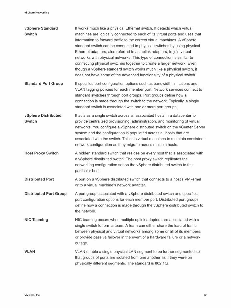
vSphere StandardSwitch
It works much like a physical Ethernet switch. It detects which virtualmachines are logically connected to each of its virtual ports and uses thatinformation to forward traffic to the correct virtual machines. A vSpherestandard switch can be connected to physical switches by using physicalEthernet adapters, also referred to as uplink adapters, to join virtualnetworks with physical networks. This type of connection is similar toconnecting physical switches together to create a larger network. Eventhough a vSphere standard switch works much like a physical switch, itdoes not have some of the advanced functionality of a physical switch.
Standard Port Group It specifies port configuration options such as bandwidth limitations andVLAN tagging policies for each member port. Network services connect tostandard switches through port groups. Port groups define how aconnection is made through the switch to the network. Typically, a singlestandard switch is associated with one or more port groups.
vSphere DistributedSwitch
It acts as a single switch across all associated hosts in a datacenter toprovide centralized provisioning, administration, and monitoring of virtualnetworks. You configure a vSphere distributed switch on the vCenter Serversystem and the configuration is populated across all hosts that areassociated with the switch. This lets virtual machines to maintain consistentnetwork configuration as they migrate across multiple hosts.
Host Proxy Switch A hidden standard switch that resides on every host that is associated witha vSphere distributed switch. The host proxy switch replicates thenetworking configuration set on the vSphere distributed switch to theparticular host.
Distributed Port A port on a vSphere distributed switch that connects to a host’s VMkernelor to a virtual machine’s network adapter.
Distributed Port Group A port group associated with a vSphere distributed switch and specifiesport configuration options for each member port. Distributed port groupsdefine how a connection is made through the vSphere distributed switch tothe network.
NIC Teaming NIC teaming occurs when multiple uplink adapters are associated with asingle switch to form a team. A team can either share the load of trafficbetween physical and virtual networks among some or all of its members,or provide passive failover in the event of a hardware failure or a networkoutage.
VLAN VLAN enable a single physical LAN segment to be further segmented sothat groups of ports are isolated from one another as if they were onphysically different segments. The standard is 802.1Q.
vSphere Networking
VMware, Inc. 12

VMkernel TCP/IPNetworking Layer
The VMkernel networking layer provides connectivity to hosts and handlesthe standard infrastructure traffic of vSphere vMotion, IP storage, FaultTolerance, and Virtual SAN.
IP Storage Any form of storage that uses TCP/IP network communication as itsfoundation. iSCSI can be used as a virtual machine datastore, and NFScan be used as a virtual machine datastore and for direct mounting of .ISOfiles, which are presented as CD-ROMs to virtual machines.
TCP SegmentationOffload
TCP Segmentation Offload, TSO, allows a TCP/IP stack to emit largeframes (up to 64KB) even though the maximum transmission unit (MTU) ofthe interface is smaller. The network adapter then separates the largeframe into MTU-sized frames and prepends an adjusted copy of the initialTCP/IP headers.
Network Services in ESXiA virtual network provides several services to the host and virtual machines.
You can enable two types of network services in ESXi:
n Connecting virtual machines to the physical network and to each other.
n Connecting VMkernel services (such as NFS, iSCSI, or vMotion) to the physical network.
VLAN ConfigurationVirtual LANs (VLANs) enable a single physical LAN segment to be further isolated so that groups of portsare isolated from one another as if they were on physically different segments.
Configuring ESXi with VLANs is recommended for the following reasons.
n It integrates the host into a pre-existing environment.
n It isolates and secures network traffic.
n It reduces network traffic congestion.
You can configure VLANs in ESXi using three methods: External Switch Tagging (EST), Virtual SwitchTagging (VST), and Virtual Guest Tagging (VGT).
With EST, all VLAN tagging of packets is performed on the physical switch. Host network adapters areconnected to access ports on the physical switch. Port groups that are connected to the virtual switchmust have their VLAN ID set to 0.
With VST, all VLAN tagging of packets is performed by the virtual switch before leaving the host. Hostnetwork adapters must be connected to trunk ports on the physical switch. Port groups that areconnected to the virtual switch must have a VLAN ID between 1 and 4094.
vSphere Networking
VMware, Inc. 13

With VGT, all VLAN tagging is done by the virtual machine. VLAN tags are preserved between the virtualmachine networking stack and external switch when frames pass to and from virtual switches. Hostnetwork adapters must be connected to trunk ports on the physical switch. For a standard switch theVLAN ID of port groups with VGT must be set to 4095. For a distributed switch the VLAN trunking policymust include the range of the VLANs to which virtual machines are connected.
Note When using VGT, you must have an 802.1Q VLAN trunking driver installed on the virtual machine.
VMware ESXi Dump Collector SupportThe ESXi Dump Collector sends the state of the VMkernel memory, that is, a core dump to a networkserver when the system encounters a critical failure.
The ESXi Dump Collector in ESXi 5.1 and later supports both vSphere Standard and DistributedSwitches. The ESXi Dump Collector can also use any active uplink adapter from the team of the portgroup that handles the VMkernel adapter for the collector.
Changes to the IP address for the ESXi Dump Collector interface are automatically updated if the IPaddresses for the configured VMkernel adapter changes. The ESXi Dump Collector also adjusts itsdefault gateway if the gateway configuration of the VMkernel adapter changes.
If you try to delete the VMkernel network adapter used by the ESXi Dump Collector, the operation failsand a warning message appears. To delete the VMkernel network adapter, disable dump collection anddelete the adapter.
There is no authentication or encryption in the file transfer session from a crashed host to the ESXi DumpCollector. You should configure the ESXi Dump Collector on a separate VLAN when possible to isolatethe ESXi core dump from regular network traffic.
For information about installing and configuring the ESXi Dump Collector, see the vSphere Installationand Setup documentation.
vSphere Networking
VMware, Inc. 14

Setting Up Networking withvSphere Standard Switches 2vSphere standard switches handle network traffic at the host level in a vSphere deployment.
This chapter includes the following topics:n vSphere Standard Switches
n Create a vSphere Standard Switch
n Port Group Configuration for Virtual Machines
n vSphere Standard Switch Properties
vSphere Standard SwitchesYou can create abstracted network devices called vSphere standard switches. You use standard switchesto provide network connectivity to hosts and virtual machines. A standard switch can bridge trafficinternally between virtual machines in the same VLAN and link to external networks.
Standard Switch OverviewTo provide network connectivity to hosts and virtual machines, you connect the physical NICs of the hoststo uplink ports on the standard switch. Virtual machines have network adapters (vNICs) that you connectto port groups on the standard switch. Every port group can use one or more physical NICs to handletheir network traffic. If a port group does not have a physical NIC connected to it, virtual machines on thesame port group can only communicate with each other but not with the external network.
VMware, Inc. 15

Figure 2‑1. vSphere standard switch architecture
Testenvironment
Production
Physical Switch
vmnic0
VM
Uplink port group
uplink port 0 uplink port 1 uplink port 2
ESXi host 2
vmnic0 vmnic1 vmnic3
Virtualport
vmnic1 vmnic3
vMotion Management
vMotiontraffic
Managementtraffic
vmknic
VM VM VM
Testenvironment
Production
VM
Uplink port group
uplink port 0 uplink port 1 uplink port 2
ESXi host 1
vMotionManagement
vMotiontraffic
Managementtraffic VM VMVM
vNIC
Networkproduction
Portgroups
Physical network adapters
A vSphere standard switch is very similar to a physical Ethernet switch. Virtual machine network adaptersand physical NICs on the host use the logical ports on the switch as each adapter uses one port. Eachlogical port on the standard switch is a member of a single port group. For information about maximumallowed ports and port groups, see the Configuration Maximums documentation.
Standard Port GroupsEach port group on a standard switch is identified by a network label, which must be unique to the currenthost. You can use network labels to make the networking configuration of virtual machines portableacross hosts. You should give the same label to the port groups in a datacenter that use physical NICsconnected to one broadcast domain on the physical network. Conversely, if two port groups areconnected to physical NICs on different broadcast domains, the port groups should have distinct labels.
For example, you can create Production and Test environment port groups as virtual machine networkson the hosts that share the same broadcast domain on the physical network.
A VLAN ID, which restricts port group traffic to a logical Ethernet segment within the physical network, isoptional. For port groups to receive the traffic that the same host sees, but from more than one VLAN ,the VLAN ID must be set to VGT (VLAN 4095).
vSphere Networking
VMware, Inc. 16

Number of Standard PortsTo ensure efficient use of host resources on hosts running ESXi 5.5 and later, the number of ports ofstandard switches are dynamically scaled up and down. A standard switch on such a host can expand upto the maximum number of ports supported on the host. The port limit is determined based on themaximum number of virtual machines that the host can handle.
Create a vSphere Standard SwitchCreate a vSphere Standard Switch to provide network connectivity for hosts, virtual machines, and tohandle VMkernel traffic. Depending on the connection type that you want to create, you can create a newvSphere Standard Switch with a VMkernel adapter, only connect physical network adapters to the newswitch, or create the switch with a virtual machine port group.
Procedure
1 In the vSphere Web Client, navigate to the host.
2 Under Manage select Networking, and select Virtual switches.
3 Click Add host networking.
4 Select a connection type for which you want to use the new standard switch and click Next.
Option Description
VMkernel Network Adapter Create a new VMkernel adapter to handle host management traffic, vMotion,network storage, fault tolerance, or Virtual SAN traffic.
Physical Network Adapter Add physical network adapters to an existing or a new standard switch.
Virtual Machine Port Group for aStandard Switch
Create a new port group for virtual machine networking.
5 Select New standard switch and click Next.
6 Add physical network adapters to the new standard switch.
a Under Assigned adapters, click Add adapters.
b Select one or more physical network adapters from the list.
c From the Failover order group drop-down menu, select from the Active or Standby failover lists.
For higher throughput and to provide redundancy, configure at least two physical networkadapters in the Active list.
d Click OK.
vSphere Networking
VMware, Inc. 17

7 If you create the new standard switch with a VMkernel adapter or virtual machine port group, enterconnection settings for the adapter or the port group.
Option Description
VMkernel adapter a Enter a label that indicates the traffic type for the VMkernel adapter, forexample vMotion.
b Set a VLAN ID to identify the VLAN that the network traffic of the VMkerneladapter will use.
c Select IPv4, Ipv6 or both.
d Select a TCP/IP stack. After you set a TCP/IP stack for the VMkernel adapter,you cannot change it later. If you select the vMotion or the ProvisioningTCP/IP stack, you will be able to use only this stack to handle vMotion orProvisioning traffic on the host.
e If you use the default TCP/IP stack, select from the available services.
f Configure IPv4 and IPv6 settings.
Virtual machine port group a Enter a network Label or the port group, or accept the generated label.
b Set the VLAN ID to configure VLAN handling in the port group.
8 On the Ready to Complete page, click OK.
What to do next
n You might need to change the teaming and failover policy of the new standard switch. For example, ifthe host is connected to an Etherchannel on the physical switch, you must configure the vSphereStandard Switch with Rout based on IP hash as a load balancing algorithm. See Teaming andFailover Policy for more information.
n If you create the new standard switch with a port group for virtual machine networking, connect virtualmachines to the port group.
Port Group Configuration for Virtual MachinesYou can add or modify a virtual machine port group to set up traffic management on a set of virtualmachines.
The Add Networking wizard in the vSphere Web Client guides you through the process to create avirtual network to which virtual machines can connect, including creating a vSphere standard switch andconfiguring settings for a network label.
When you set up virtual machine networks, consider whether you want to migrate the virtual machines inthe network between hosts. If so, be sure that both hosts are in the same broadcast domain—that is, thesame Layer 2 subnet.
ESXi does not support virtual machine migration between hosts in different broadcast domains becausethe migrated virtual machine might require systems and resources that it would no longer have access toin the new network. Even if your network configuration is set up as a high-availability environment orincludes intelligent switches that can resolve the virtual machine’s needs across different networks, youmight experience lag times as the Address Resolution Protocol (ARP) table updates and resumesnetwork traffic for the virtual machines.
vSphere Networking
VMware, Inc. 18

Virtual machines reach physical networks through uplink adapters. A vSphere standard switch cantransfer data to external networks only when one or more network adapters are attached to it. When twoor more adapters are attached to a single standard switch, they are transparently teamed.
Add a Virtual Machine Port Group with the vSphere Web ClientCreate port groups in a vSphere standard switch to provide connectivity and common networkconfiguration for a set of virtual machines.
Procedure
1 In the vSphere Web Client, navigate to the host.
2 Right-click the host in the navigator and select All vCenter Actions > Add Networking.
3 In Select connection type, select Virtual Machine Port Group for a Standard Switch and clickNext.
4 In Select target device, select an existing standard switch or create a new standard switch.
5 If the new port group is for an existing standard switch, navigate to the switch.
a Click Browse.
b Select a standard switch from the list and click OK.
c Click Next and go to Step 7.
6 (Optional) In the Create a Standard Switch page, assign physical network adapters to the standardswitch.
You can create a standard switch with or without adapters.
If you create a standard switch without physical network adapters, all traffic on that switch is confinedto that switch. No other hosts on the physical network or virtual machines on other standard switchescan send or receive traffic over this standard switch. You might create a standard switch withoutphysical network adapters if you want a group of virtual machines to be able to communicate witheach other, but not with other hosts or with virtual machines outside the group.
a Click Add adapters.
b Select an adapter from the Network Adapters list.
c Use the Failover order group drop-down menu to assign the adapter to Active adapters,Standby adapters, or Unused adapters, and click OK.
d (Optional) Use the up and down arrows in the Assigned adapters list to change the position ofthe adapter if needed.
e Click Next.
vSphere Networking
VMware, Inc. 19

7 In the Connection settings page, identify traffic through the ports of the group.
a Type a Network Label for the port group, or accept the generated label.
b Set the VLAN ID to configure VLAN handling in the port group.
The VLAN ID also reflects the VLAN tagging mode in the port group.
VLAN Tagging Mode VLAN ID Description
External Switch Tagging (EST) 0 The virtual switch does not pass traffic associated with a VLAN.
Virtual Switch Tagging (VST) From 1 to 4094 The virtual switch tags traffic with the entered tag.
Virtual Guest Tagging (VGT) 4095 Virtual machines handle VLANs. The virtual switch passes traffic fromany VLAN.
c Click Next.
8 Review the port group settings in the Ready to complete page, and click Finish.
Click Back if you want to change any settings.
Edit a Standard Switch Port Group in the vSphere Web ClientBy using the vSphere Web Client edit the name and VLAN ID of a standard switch port group, andoverride networking policies at the port group level.
Procedure
1 In the vSphere Web Client, navigate to the host.
2 On the Manage tab, click Networking, and select Virtual switches.
3 Select a standard switch from the list.
The topology diagram of the switch appears.
4 In the topology diagram of the switch, click the name of the port group.
5 Click Edit under the topology diagram title.
6 In the Properties section, rename the port group in the Network Label text field.
7 Configure VLAN tagging in the VLAN ID drop-down menu.
VLAN Tagging Mode VLAN ID Description
External Switch Tagging (EST) 0 The virtual switch does not pass traffic associated with a VLAN.
Virtual Switch Tagging (VST) From 1 to 4094 The virtual switch tags traffic with the entered tag.
Virtual Guest Tagging (VGT) 4095 Virtual machines handle VLANs. The virtual switch passes traffic from anyVLAN.
8 In the Security section, override the switch settings for protection against MAC addressimpersonation and for running virtual machines in promiscuous mode.
9 In the Traffic Shaping section, override at the port group level the size of average and peakbandwidth and of bursts.
vSphere Networking
VMware, Inc. 20

10 In the Teaming and Failover section, override the teaming and failover settings inherited from thestandard switch.
You can configure traffic distribution and rerouting between the physical adapters associated with theport group. You can also change the order in which host physical adapters are used upon failure.
11 Click OK.
Remove a Port Group from a vSphere Standard Switch in thevSphere Web ClientYou can remove port groups from vSphere standard switches in case you no longer need the associatedlabeled networks.
Prerequisites
Verify that there are no powered-on virtual machines connected to the port group that you want toremove.
Procedure
1 In the vSphere Web Client, navigate to the host.
2 On the Manage tab, click Networking, and select Virtual switches.
3 Select the standard switch.
4 From the topology diagram of the switch, select the port group that you want to remove by clicking itslabel.
5 From the toolbar in the switch topology, click the Remove selected port group action icon .
vSphere Standard Switch PropertiesvSphere Standard Switch settings control switch-wide defaults for ports, which can be overridden by portgroup settings for each standard switch. You can edit standard switch properties, such as the uplinkconfiguration and the number of available ports.
Number of Ports on ESXi HostsTo ensure efficient use of host resources on hosts running ESXi 5.5 and later, the ports of virtual switchesare dynamically scaled up and down. A switch on such a host can expand up to the maximum number ofports supported on the host. The port limit is determined based on the maximum number of virtualmachines that the host can handle.
vSphere Networking
VMware, Inc. 21

Each virtual switch on hosts running ESXi 5.1 and earlier provides a finite number of ports through whichvirtual machines and network services can reach one or more networks. You have to increase ordecrease the number of ports manually according to your deployment requirements.
Note Increasing the port number of a switch leads to reserving and consuming more resources on thehost. If some ports are not occupied, host resources that might be necessary for other operations remainlocked and unused.
Change the Size of the MTU on a vSphere Standard SwitchChange the size of the maximum transmission unit (MTU) on a vSphere Standard Switch to improve thenetworking efficiency by increasing the amount of payload data transmitted with a single packet, that is,enabling jumbo frames.
Procedure
1 In the vSphere Web Client, navigate to the host.
2 On the Manage tab, click Networking, and select Virtual switches.
3 Select a standard switch from the table and click Edit settings.
4 Change the MTU (bytes) value for the standard switch.
You can enable jumbo frames by setting MTU (bytes) to a number greater than 1500. You cannot setan MTU size greater than 9000 bytes.
5 Click OK.
Change the Speed of a Physical Adapter in thevSphere Web ClientA physical adapter can become a bottleneck for network traffic if the adapter speed does not matchapplication requirements. You can change the connection speed and duplex of a physical adapter totransfer data in compliance with traffic rate.
Procedure
1 Browse to a host in the vSphere Web Client navigator.
2 Click the Manage tab, and select Physical adapters from Networking.
The physical network adapters of the host appear in a table that contains details for each physicalnetwork adapter.
3 Select the physical network adapter from the list and click Edit.
4 Select speed and duplex mode of the physical network adapter from the drop-down menu.
5 (Optional) If the physical adapter supports SR-IOV, enable it and configure the number of virtualfunctions to use for virtual machine networking.
6 Click OK.
vSphere Networking
VMware, Inc. 22

Add and Team Physical Adapters in a Standard Switch in thevSphere Web ClientAssign a physical adapter to a standard switch to provide connectivity to virtual machines and VMkerneladapters on the host. You can form a team of NICs to distribute traffic load and to configure failover.
NIC teaming combines multiple network connections to increase throughput and provide redundancyshould a link fail. To create a team, you associate multiple physical adapters to a single vSphere standardswitch.
Procedure
1 In the vSphere Web Client, navigate to the host.
2 On the Manage tab, click Networking, and select Virtual switches.
3 Select the standard switch you want to add a physical adapter to.
4 Click Manage the physical network adapters.
5 Click Add adapters.
6 Select one or more physical network adapters from the list and select the Failover order group toassign the adapters to, and click OK.
The selected adapters appear in the selected failover group list under the Assigned Adapters list.
7 (Optional) Use the up and down arrows to change the position of an adapter in the failover groups.
8 Click OK to apply the physical adapter configuration.
View the Topology Diagram of a vSphere Standard Switch in thevSphere Web ClientYou can examine the structure and components of a vSphere standard switch by using its topologydiagram.
The topology diagram of a standard switch provides a visual representation of the adapters and portgroups connected to the switch.
From the diagram you can edit the settings of a selected port group and of a selected adapter.
Procedure
1 In the vSphere Web Client, navigate to the host.
2 On the Manage tab, click Networking, and select Virtual switches.
3 Select the standard switch from the list.
The diagram appears under the list of virtual switches on the host.
vSphere Networking
VMware, Inc. 23

Setting Up Networking withvSphere Distributed Switches 3With vSphere distributed switches you can set up and configure networking in a vSphere environment.
This chapter includes the following topics:n vSphere Distributed Switch Architecture
n Create a vSphere Distributed Switch with the vSphere Web Client
n Upgrade a vSphere Distributed Switch to a Later Version with the vSphere Web Client
n Edit General and Advanced vSphere Distributed Switch Settings in the vSphere Web Client
n Managing Networking on Multiple Hosts on a vSphere Distributed Switch
n Managing Networking on Host Proxy Switches
n Distributed Port Groups
n Working with Distributed Ports
n Configuring Virtual Machine Networking on a vSphere Distributed Switch
n Topology Diagrams of a vSphere Distributed Switch in the vSphere Web Client
n vSphere Distributed Switch Health Check
n Export, Import, and Restore Distributed Switch Configurations
n Private VLANs
n LACP Support on a vSphere Distributed Switch
vSphere Distributed Switch ArchitectureA vSphere Distributed Switch provides centralized management and monitoring of the networkingconfiguration of all hosts that are associated with the switch. You set up a distributed switch onvCenter Server system, and its settings are propagated to all hosts that are associated with the switch.
VMware, Inc. 24

Figure 3‑1. vSphere Distributed Switch Architecture
Physical NICs
Uplink port group
Testenvironment vMotion
Test environmentProduction
Production
uplink port 0 uplink port 1 uplink port 2
Uplink0 Uplink1 Uplink2
ESXi host 1
vSphere Distributed Switch
Physical Switch
vmnic0
VM VM VM VM VM vMotion Management
Uplink port group
uplink port 0 uplink port 1 uplink port 2
ESXi host 2
vmnic0 vmnic1 vmnic3
vNIC VMkernaladapter(vmknic)
Distributedport groups
vmnic1 vmnic3
Uplink port group
vCenter Server
Management Testenvironment vMotionProduction Management
vMotion Management
You associate a vSphere Distributed Switch with a datacenter on a vCenter Server system. Thenetworking configuration and management for all hosts that are associated with the switch is centralizedon the vCenter Server system. Every associated host has a host proxy switch that contains thenetworking settings for the host that are configured on distributed switch.
For example, suppose you associate ESXi A and ESXi B hosts to a distributed switch and connectphysical NIC vmnic1 of both hosts to uplink 1 on the switch. As a result, vmnic1 of hosts ESXi A and ESXiB is connected to uplink 1 on the distributed switch. On the host proxy switches of both hosts, physicalNIC vmnic1 is connected to uplink port 1.
To ensure efficient use of host resources, the number of distributed ports of proxy switches aredynamically scaled up and down on hosts running ESXi 5.5 and later. A proxy switch on such a host canexpand up to the maximum number of ports supported on the host. The port limit is determined based onthe maximum number of virtual machines that the host can handle.
vSphere Networking
VMware, Inc. 25

A distributed switch has one or more distributed port groups. You use distributed port groups to providenetworking connectivity to virtual machines and to accommodate VMkernel traffic. You identify eachdistributed port group by using a network label, which must be unique to the current datacenter. A copy ofevery distributed port group that you create is also available on the host proxy switches of all hosts thatare associated with the distributed switch. The policies that you configure to a distributed port group areconsistent for all hosts in the distributed switch.
A VLAN ID, which restricts port group traffic to a logical Ethernet segment within the physical network, isoptional.
In addition to vSphere Distributed Switches, vSphere 5 also provides support for third-party virtualswitches. For information about configuring the Cisco Nexus 1000v switch, see the Cisco Systems Website.
Create a vSphere Distributed Switch with thevSphere Web ClientCreate a vSphere distributed switch on a datacenter to handle the networking configuration of multiplehosts at a time from a central place.
Procedure
1 In the vSphere Web Client, navigate to a datacenter.
2 In the navigator, right-click the datacenter and select New Distributed Switch.
3 In Name and Location, type a name for the new distributed switch, or accept the generated name,and click Next.
4 In Select version, select a distributed switch version and click Next.
Option Description
Distributed Switch: 5.5.0 Compatible with ESXi 5.5 and later.
Distributed Switch: 5.1.0 Compatible with VMware ESXi 5.1 and later. Features released with later vSpheredistributed switch versions are not supported.
Distributed Switch: 5.0.0 Compatible with VMware ESXi 5.0 and later.
Features released with later vSphere distributed switch versions are notsupported.
Distributed Switch: 4.1.0 Compatible with ESX/ESXi version 4.1 and later.
Features released with later vSphere distributed switch versions are notsupported.
Distributed Switch: 4.0.0 Compatible with ESX/ESXi version 4.0 and later.
Features released with later vSphere distributed switch versions are notsupported.
vSphere Networking
VMware, Inc. 26

5 In Edit Settings configure the distributed switch settings.
a Use the arrow buttons to select the Number of uplinks.
Uplink ports connect the distributed switch to physical NICs on associated hosts. The number ofuplink ports is the maximum number of allowed physical connections to the distributed switch perhost.
b Use the drop-down menu to enable or disable Network I/O Control.
By using Network I/O Control you can prioritize the access to network resources for certain typesof infrastructure and workload traffic according to the requirements of your deployment. NetworkI/O Control continuously monitors the I/O load over the network and dynamically allocatesavailable resources.
c Select the Create a default port group check box to create a new distributed port group withdefault settings for this switch.
d (Optional) To create a default distributed port group, type the port group name in the Port groupname, or accept the generated name.
If your system has custom port group requirements, create distributed port groups that meetthose requirements after you add the distributed switch.
e Click Next.
6 In Ready to complete, review the settings you selected and click Finish.
Use the Back button to edit any settings.
A distributed switch is created on the datacenter. You can view the features supported on the distributedswitch as well as other details by navigating to the new distributed switch and clicking the Summary tab.
What to do next
Add hosts to the distributed switch and configure their network adapters on the switch.
Upgrade a vSphere Distributed Switch to a Later Versionwith the vSphere Web ClientYou can upgrade vSphere Distributed Switch version 4.0, 4.1, 5.0, or 5.1 to a later version. The upgradelets the distributed switch take advantage of features that are available only in the later version.
vSphere Networking
VMware, Inc. 27

The upgrade of a distributed switch is a non-disruptive operation, that is, the hosts and virtual machinesattached to the switch do not experience any downtime.
Note To be able to restore the connectivity of the virtual machines and VMkernel adapters if the upgradefails, back up the configuration of the distributed switch.
You can export the switch configuration before you upgrade vCenter Server if you upgrade fromvCenter Server 5.1. If you upgrade vCenter Server from a version earlier than 5.1, back up the switchconfiguration after you upgrade vCenter Server to version 5.5.
If the upgrade is not successful, to recreate the switch with its port groups and connected hosts, you canimport the switch configuration file with the Preserve original distributed switch and port groupidentifiers option selected in the Import Distributed Switch wizard.
See Export vSphere Distributed Switch Configurations with the vSphere Web Client and Import a vSphereDistributed Switch Configuration by Using the vSphere Web Client.
Prerequisites
n Upgrade vCenter Server to the version 5.5.
n Upgrade all hosts connected to the distributed switch to ESXi 5.5.
Procedure
1 In the vSphere Web Client, navigate to the distributed switch.
2 Right-click the distributed switch and select Upgrade Distributed Switch.
3 Select the vSphere Distributed Switch version that you want to upgrade the switch to and click Next.
Option Description
Version 5.5.0 Compatible with ESXi version 5.5 and later.
Version 5.1.0 Compatible with ESXi version 5.1 and later. Features released with later vSphereDistributed Switch versions are not supported.
Version 5.0.0 Compatible with ESXi version 5.0 and later. Features released with later vSphereDistributed Switch versions are not supported.
Version 4.1.0 Compatible with ESX/ESXi version 4.1 and later. Features released with latervSphere Distributed Switch versions are not supported.
4 Review host compatibility and click Next.
Some VMware ESX instances that are running on the distributed switch might be incompatible withthe selected upgrade version. Upgrade or remove incompatible hosts, or select another upgradeversion for the distributed switch.
5 Review your settings and click Finish.
After you upgrade the vSphere Distributed Switch, you cannot revert it to an earlier version. You cannotadd VMware ESX hosts that are running an earlier incompatible version with the new switch version.
vSphere Networking
VMware, Inc. 28

Edit General and Advanced vSphere Distributed SwitchSettings in the vSphere Web ClientGeneral settings for a vSphere Distributed Switch include the switch name and number of uplinks.Advanced settings for a distributed switch include Cisco Discovery Protocol and the maximum MTU forthe switch.
Procedure
1 In the vSphere Web Client, navigate to the distributed switch.
2 Click Manage tab, click Settings, and select Properties.
3 Click Edit.
4 Click General to edit the vSphere Distributed Switch settings.
Option Description
Name Type the name for the distributed switch.
Number of uplinks Select the number of uplink ports for the distributed switch.
Click Edit Uplink Names to change the names of the uplinks.
Number of ports The number of ports for this distributed switch. This cannot be edited.
Network I/O Control Use the drop-down menu to enable or disable Network I/O control.
Description Add or modify a description of the distributed switch settings.
5 Click Advanced to edit the vSphere Distributed Switch settings.
Option Description
MTU (Bytes) Maximum MTU size for the vSphere Distributed Switch. To enable jumbo frames,set a value greater than 1500 bytes.
Discovery Protocol a Select Cisco Discovery Protocol, Link Layer Discovery Protocol, or disabledfrom the Type drop-down menu.
b Set Operation to Listen, Advertise, or Both.
For information about Discovery Protocol, see Switch Discovery Protocol.
Administrator Contact Type the name and other details of the administrator for the distributed switch.
6 Click OK.
Managing Networking on Multiple Hosts on a vSphereDistributed SwitchYou create and manage virtual networks on a vSphere Distributed Switch by adding hosts to the switchand connecting their network adapters to the switch. To create uniform networking configurationthroughout multiple hosts on the distributed switch, you can use a host as a template and apply itsconfiguration to other hosts.
vSphere Networking
VMware, Inc. 29

n Tasks for Managing Host Networking on a vSphere Distributed Switch
You can add new hosts to a vSphere Distributed Switch, connect network adapters to the switch,and remove hosts from the switch. In a production environment, you might need to keep the networkconnectivity up for virtual machines and VMkernel services while you manage host networking onthe distributed switch.
n Add Hosts to a vSphere Distributed Switch in the vSphere Web Client
To manage the networking of your vSphere environment by using a vSphere Distributed Switch, youmust associate hosts with the switch. You connect the physical NICs, VMkernel adapters, and virtualmachine network adapters of the hosts to the distributed switch.
n Configure Physical Network Adapters on a vSphere Distributed Switch in the vSphere Web Client
For hosts that are associated with a distributed switch, you can assign physical NICs to uplinks onthe switch. You can configure physical NICs on the distributed switch for multiple hosts at a time.
n Migrate VMkernel Adapters to a vSphere Distributed Switch in the vSphere Web Client
Migrate VMkernel adapters to a distributed switch if you want to handle the traffic for VMkernelservices by using only this switch and you no longer need the adapters on other standard ordistributed switches.
n Create a VMkernel Adapter on a vSphere Distributed Switch in the vSphere Web Client
Create a VMkernel adapter on hosts associated with a distributed switch to provide networkconnectivity to the hosts and to handle the traffic for vSphere vMotion, IP storage, Fault Tolerancelogging, and Virtual SAN. You can create VMkernel adapters on multiple hosts simultaneously byusing the Add and Manage Hosts wizard.
n Migrate Virtual Machine Networking to the vSphere Distributed Switch in the vSphere Web Client
To manage virtual machine networking by using a distributed switch, migrate virtual machinenetwork adapters to labeled networks on the switch.
n Use a Host as a Template to Create a Uniform Networking Configuration on a vSphere DistributedSwitch in the vSphere Web Client
If you plan to have hosts with a uniform networking configuration, you can select a host as atemplate and apply its configuration for physical NICs and VMkernel adapters to other hosts on thedistributed switch.
n Remove Hosts from a vSphere Distributed Switch in the vSphere Web Client
Remove hosts from a vSphere distributed switch if you have configured a different switch for thehosts.
Tasks for Managing Host Networking on a vSphere DistributedSwitchYou can add new hosts to a vSphere Distributed Switch, connect network adapters to the switch, andremove hosts from the switch. In a production environment, you might need to keep the networkconnectivity up for virtual machines and VMkernel services while you manage host networking on thedistributed switch.
vSphere Networking
VMware, Inc. 30

Adding Hosts to a vSphere Distributed SwitchConsider preparing your environment before you add new hosts to a distributed switch.
n Create distributed port groups for virtual machine networking.
n Create distributed port groups for VMkernel services. For example, create distributed port groups formanagement network, vMotion, and Fault Tolerance.
n Configure enough uplinks on the distributed switch for all physical NICs that you want to connect tothe switch. For example, if the hosts that you want to connect to the distributed switch have eightphysical NICs each, configure eight uplinks on the distributed switch.
n Make sure that the configuration of the distributed switch is prepared for services with specificnetworking requirements. For example, iSCSI has specific requirements for the teaming and failoverconfiguration of the distributed port group where you connect the iSCSI VMkernel adapter.
You can use the Add and Manage Hosts wizard in the vSphere Web Client to add multiple hosts at atime.
Managing Network Adapters on a vSphere Distributed SwitchAfter you add hosts to a distributed switch, you can connect physical NICs to uplinks on the switch,configure virtual machine network adapters, and manage VMkernel networking.
If some hosts on a distributed switch are associated to other switches in your datacenter, you can migratenetwork adapters to or from the distributed switch.
If you migrate virtual machine network adapters or VMkernel adapters, make sure that the destinationdistributed port groups have at least one active uplink, and the uplink is connected to a physical NIC onthe hosts. Another approach is to migrate physical NICs, virtual network adapters, and VMkernel adapterssimultaneously.
If you migrate physical NICs, leave at least one active NIC that handles the traffic of port groups. Forexample, if vmnic0 and vmnic1 handle the traffic of the VM Network port group, migrate vmnic0 and leavevmnic1 connected to the group.
Removing Hosts from a vSphere Distributed SwitchBefore you remove hosts from a distributed switch, you must migrate the network adapters that are in useto a different switch.
n To add hosts to a different distributed switch, you can use the Add and Manage Hosts wizard tomigrate the network adapters on the hosts to the new switch all together. You can then remove thehosts safely from their current distributed switch.
vSphere Networking
VMware, Inc. 31

n To migrate host networking to standard switches, you must migrate the network adapters on stages.For example, remove physical NICs on the hosts from the distributed switch by leaving one physicalNIC on every host connected to the switch to keep the network connectivity up. Next, attach thephysical NICs to the standard switches and migrate VMkernel adapters and virtual machine networkadapters to the switches. Lastly, migrate the physical NIC that you left connected to the distributedswitch to the standard switches.
Add Hosts to a vSphere Distributed Switch in thevSphere Web ClientTo manage the networking of your vSphere environment by using a vSphere Distributed Switch, you mustassociate hosts with the switch. You connect the physical NICs, VMkernel adapters, and virtual machinenetwork adapters of the hosts to the distributed switch.
Prerequisites
n Verify that enough uplinks are available on the distributed switch to assign to the physical NICs thatyou want to connect to the switch.
n Verify that there is at least one distributed port group on the distributed switch.
n Verify that the distributed port group have active uplinks configured in its teaming and failover policy.
If you migrate or create VMkernel adapters for iSCSI, verify that the teaming and failover policy of thetarget distributed port group meets the requirements for iSCSI:
n Verify that only one uplink is active, the standby list is empty, and the rest of the uplinks are unused.
n Verify that only one physical NIC per host is assigned to the active uplink.
Procedure
1 In the vSphere Web Client, navigate to the distributed switch.
2 From the Actions menu, select Add and Manage Hosts.
3 Select Add hosts and click Next.
4 Click New hosts, select from the hosts in your datacenter, and click OK.
5 Select the tasks for configuring network adapters to the distributed switch and click Next.
6 Configure physical NICs on the distributed switch.
a From the On other switches/unclaimed list, select a physical NIC.
If you select physical NICs that are already connected to other switches, they are migrated to thecurrent distributed switch.
b Click Assign uplink.
c Select an uplink and click OK.
vSphere Networking
VMware, Inc. 32

For consistent network configuration, you can connect one and the same physical NIC on every hostto the same uplink on the distributed switch.
For example, if you are adding two hosts connect vmnic1 on of each host to Uplink1 on thedistributed switch.
7 Click Next.
8 Configure VMkernel adapters.
a Select a VMkernel adapter and click Assign port group.
b Select a distributed port group and click OK.
9 Review the impacted services as well as the level of impact.
Option Description
No impact The service will continue its normal function after the new networkingconfiguration is applied.
Important impact The normal function of the service might be disrupted if the new networkingconfiguration is applied.
Critical impact The normal function of the service will be interrupted if the new networkingconfiguration is applied.
a If impact on a service is important or critical, click the service and review the reasons that are
displayed in the Analysis details pane.
b After you troubleshoot the impact on all dependent services, proceed with your networkingconfiguration.
10 Click Next.
11 Configure virtual machine networking.
a To connect all network adapters of a virtual machine to a distributed port group, select the virtualmachine, or select an individual network adapter to connect only that adapter.
b Click Assign port group.
c Select a distributed port group from the list and click OK.
12 Click Next and click Finish.
What to do next
Having hosts associated with the distributed switch, you can manage physical NICs, VMkernel adapters,and virtual machine network adapters.
Configure Physical Network Adapters on a vSphere DistributedSwitch in the vSphere Web ClientFor hosts that are associated with a distributed switch, you can assign physical NICs to uplinks on theswitch. You can configure physical NICs on the distributed switch for multiple hosts at a time.
vSphere Networking
VMware, Inc. 33

For consistent networking configuration throughout all hosts, you can assign the same physical NIC onevery host to the same uplink on the distributed switch. For example, you can assign vmnic1 from hostsESXi A and ESXi B to Uplink 1.
Procedure
1 In the vSphere Web Client, navigate to the distributed switch.
2 From the Actions menu, select Add and Manage Hosts.
3 Select Manage host networking and click Next.
4 Click Attached hosts and select from the hosts that are associated with the distributed switch.
5 Click Next.
6 Select Manage physical adapters and click Next.
7 From the On other switches/unclaimed list select a physical NIC .
If you select physical NICs that are already assigned to other switches, they are migrated to thecurrent distributed switch.
8 Click Assign uplink.
9 Select an uplink or select Auto-assign.
10 Click Next.
11 Review the impacted services as well as the level of impact.
Option Description
No impact The service will continue its normal function after the new networkingconfiguration is applied.
Important impact The normal function of the service might be disrupted if the new networkingconfiguration is applied.
Critical impact The normal function of the service will be interrupted if the new networkingconfiguration is applied.
a If impact on a service is important or critical, click the service and review the reasons that are
displayed in the Analysis details pane.
b After you troubleshoot the impact on all dependent services, proceed with your networkingconfiguration.
12 Click Next and click Finish.
Migrate VMkernel Adapters to a vSphere Distributed Switch in thevSphere Web ClientMigrate VMkernel adapters to a distributed switch if you want to handle the traffic for VMkernel servicesby using only this switch and you no longer need the adapters on other standard or distributed switches.
vSphere Networking
VMware, Inc. 34

Procedure
1 In the vSphere Web Client, navigate to the distributed switch.
2 From the Actions menu, select Add and Manage Hosts.
3 Select Manage host networking and click Next.
4 Click Attached hosts and select from the hosts that are associated with the distributed switch.
5 Click Next.
6 Select Manage VMkernel adapters and click Next.
7 Select the adapter and click Assign port group.
8 Select a distributed port group and click OK.
9 Click Next.
10 Review the impacted services as well as the level of impact.
Option Description
No impact The service will continue its normal function after the new networkingconfiguration is applied.
Important impact The normal function of the service might be disrupted if the new networkingconfiguration is applied.
Critical impact The normal function of the service will be interrupted if the new networkingconfiguration is applied.
a If impact on a service is important or critical, click the service and review the reasons that are
displayed in the Analysis details pane.
b After you troubleshoot the impact on all dependent services, proceed with your networkingconfiguration.
11 Click Next and click Finish.
Create a VMkernel Adapter on a vSphere Distributed Switch in thevSphere Web ClientCreate a VMkernel adapter on hosts associated with a distributed switch to provide network connectivityto the hosts and to handle the traffic for vSphere vMotion, IP storage, Fault Tolerance logging, and VirtualSAN. You can create VMkernel adapters on multiple hosts simultaneously by using the Add and ManageHosts wizard.
You should dedicate one distributed port group for each VMkernel adapter. One VMkernel adapter shouldhandle only one traffic type.
Procedure
1 In the vSphere Web Client, navigate to the distributed switch.
2 From the Actions menu, select Add and Manage Hosts.
vSphere Networking
VMware, Inc. 35

3 Select Manage host networking and click Next.
4 Click Attached hosts and select from the hosts that are associated with the distributed switch.
5 Click Next.
6 Select Manage VMkernel adapters and click Next.
7 Click New adapter.
The Add Networking wizard opens.
8 On the Select target device page of the Add Networking wizard, select a distributed port group.
9 On the Port properties page, configure the settings for the VMkernel adapter.
Option Description
Network label The network label is inherited from the label of the distributed port group.
IP settings Select IPv4, IPv6, or both.
Note The IPv6 option does not appear on hosts that do not have IPv6 enabled.
TCP/IP stack If custom stacks are available, select one from the list.
Enable services You can enable services for the default TCP/IP stack on the host. Select from theavailable services:n vMotion traffic. Enables the VMkernel adapter to advertise itself to another
host as the network connection where vMotion traffic is sent. You can enablethis property for only one vMotion and IP storage VMkernel adapter per host.If this property is not enabled for any VMkernel adapter, migration withvMotion to the selected host is not possible.
n Fault Tolerance traffic. Enables Fault Tolerance logging on the host.n Management traffic. Enables the management traffic for the host and
vCenter Server. Typically, hosts have such a VMkernel adapter created whenthe ESXi software is installed. You can create another VMkernel adapter formanagement traffic on the host to provide redundancy.
n Virtual SAN. Enables the Virtual SAN traffic on the host. Every host that ispart of a Virtual SAN cluster must have such a VMkernel adapter.
10 (Optional) On the IPv4 settings page, select an option for obtaining IP addresses.
Option Description
Obtain IP settings automatically Use DHCP to obtain IP settings.
Use static IP settings Type the IPv4 IP address and subnet mask for the VMkernel adapter.
The VMkernel Default Gateway and DNS server addresses for IPv4 are obtainedfrom the selected TCP/IP stack.
vSphere Networking
VMware, Inc. 36

11 (Optional) On the IPv6 settings page, select an option for obtaining IPv6 addresses.
Option Description
Obtain IPv6 addresses automaticallythrough DHCP
Use DHCP to obtain IPv6 addresses.
Obtain IPv6 addresses automaticallythrough Router Advertisement
Use router advertisement to obtain IPv6 addresses.
Static IPv6 addresses a Click Add to add a new IPv6 address.
b Type the IPv6 address and subnet prefix length, and click OK.
c To change the VMkernel default gateway, click Edit.
12 Review your setting selections in the Ready to complete page and click Finish.
13 Follow the prompts to complete the wizard.
Migrate Virtual Machine Networking to the vSphere DistributedSwitch in the vSphere Web ClientTo manage virtual machine networking by using a distributed switch, migrate virtual machine networkadapters to labeled networks on the switch.
Prerequisites
Verify that at least one distributed port group intended for virtual machine networking exists on thedistributed switch.
Procedure
1 In the vSphere Web Client, navigate to the distributed switch.
2 From the Actions menu, select Add and Manage Hosts.
3 Select Manage host networking and click Next.
4 Click Attached hosts and select from the hosts that are associated with the distributed switch.
5 Click Next.
6 Select Migrate virtual machine networking and click Next.
7 Configure virtual machine network adapters to the distributed switch.
a To connect all network adapters of a virtual machine to a distributed port group, select the virtualmachine, or select an individual network adapter to connect only that adapter.
b Click Assign port group.
c Select a distributed port group from the list and click OK.
8 Click Next and click Finish.
vSphere Networking
VMware, Inc. 37

Use a Host as a Template to Create a Uniform NetworkingConfiguration on a vSphere Distributed Switch in thevSphere Web ClientIf you plan to have hosts with a uniform networking configuration, you can select a host as a template andapply its configuration for physical NICs and VMkernel adapters to other hosts on the distributed switch.
Procedure
1 In the vSphere Web Client, navigate to the distributed switch.
2 From the Actions menu, select Add and Manage Hosts.
3 Select a task for managing host networking and click Next.
4 Select the hosts to add or manage on the distributed switch.
5 At the bottom of the dialog box, select Configure identical networking settings on multiple hostsand click Next.
6 Select a host to use as a template and click Next.
7 Select the network adapter tasks and click Next.
8 On the Manage physical network adapters and Manage VMkernel network adapters pages, make theconfiguration changes that you need on the template host, and click Apply to all for all other hosts.
9 On the Ready to complete page, click Finish.
Example: Configure Physical and VMkernel Adapters by Using a TemplateHostUse the template host mode in the Add and Manage Hosts wizard to create a uniform networkingconfiguration among all the hosts on a distributed switch.
On the Manage physical network adapters page of the wizard, assign two physical NICs to uplinks on thetemplate host, and then click Apply to all to create the same configuration on the other host.
vSphere Networking
VMware, Inc. 38

Figure 3‑2. Applying Physical NICs Configuration on a vSphere Distributed Switch by Using aTemplate Host
On the Manage VMkernel network adapters page, assign a VMkernel adapter to a port group and clickApply to all to apply the same configuration to the other host.
After you click the Apply to all button, the destination VMkernel adapter has both the Modified and theReassigned qualifiers. The Modified qualifier appears, because when you click the Apply to all button,vCenter Server copies the configuration specifications of the template VMKernel adapter to thedestination VMkernel adapter even if the configurations of the template and destination adapters areidentical. As a result, the destination adapters are always modified.
vSphere Networking
VMware, Inc. 39
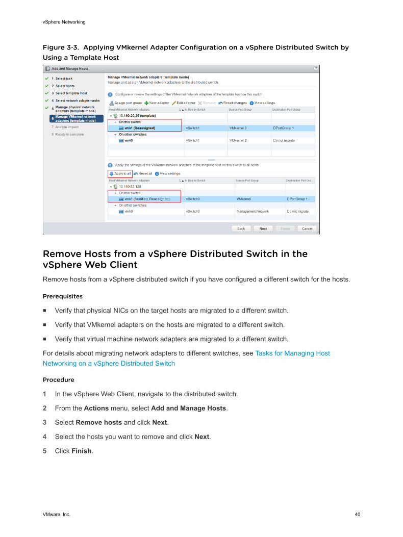
Figure 3‑3. Applying VMkernel Adapter Configuration on a vSphere Distributed Switch byUsing a Template Host
Remove Hosts from a vSphere Distributed Switch in thevSphere Web ClientRemove hosts from a vSphere distributed switch if you have configured a different switch for the hosts.
Prerequisites
n Verify that physical NICs on the target hosts are migrated to a different switch.
n Verify that VMkernel adapters on the hosts are migrated to a different switch.
n Verify that virtual machine network adapters are migrated to a different switch.
For details about migrating network adapters to different switches, see Tasks for Managing HostNetworking on a vSphere Distributed Switch
Procedure
1 In the vSphere Web Client, navigate to the distributed switch.
2 From the Actions menu, select Add and Manage Hosts.
3 Select Remove hosts and click Next.
4 Select the hosts you want to remove and click Next.
5 Click Finish.
vSphere Networking
VMware, Inc. 40

Managing Networking on Host Proxy SwitchesYou can change the configuration of the proxy switch on every host that is associated with a vSpheredistributed switch. You can manage physical NICs, VMkernel adapters, and virtual machine networkadapters.
For details about setting up VMkernel networking on host proxy switches, see Create a VMkernel Adapteron a vSphere Distributed Switch in the vSphere Web Client.
Migrate Network Adapters on a Host to a vSphere DistributedSwitch in the vSphere Web ClientFor hosts associated with a distributed switch, you can migrate network adapters from a standard switchto the distributed switch. You can migrate physical NICs, VMkernel adapters, and virtual machine networkadapters at the same time.
If you want to migrate virtual machine network adapters or VMkernel adapters, make sure that thedestination distributed port groups have at least one active uplink, and the uplink is connected to aphysical NIC on this host. Alternatively, migrate physical NICs, virtual network adapters, and VMkerneladapters at once.
If you want to migrate physical NICs, make sure that the source port groups on the standard switch haveat least one physical NIC to handle their traffic. For example, if you migrate a physical NIC that isassigned to a port group for virtual machine networking, make sure that the port group is connected to atleast one physical NIC. Otherwise the virtual machines on same VLAN on the standard switch will haveconnectivity between each other but not to the external network.
Procedure
1 In the vSphere Web Client, navigate to the host.
2 On the Manage tab, click Networking, and select Virtual switches.
3 Select the destination distributed switch and click Migrate physical or virtual network adapters.
4 Select the tasks for migrating network adapters and click Next.
5 Configure physical NICs.
a From the On other switches/unclaimed list, select a physical NIC and click Assign uplink.
b Select an uplink and click OK.
c Click Next.
6 Configure VMkernel adapters.
a Select an adapter and click Assign port group.
b Select a distributed port group and click OK.
You should connect one VMkernel adapter to one distributed port group at a time.
c Click Next.
vSphere Networking
VMware, Inc. 41

7 Review the services that are affected from the new networking configuration.
a If there is an important or serious impact reported on a service, click the service and review theanalysis details.
For example, an important impact on iSCSI might be reported as a result from an incorrectteaming and failover configuration on the distributed port group where you migrate the iSCSIVMkernel adapter. You must leave one active uplink on the teaming and failover order of thedistributed port group, leave the standby list empty, and move the rest of the uplinks to unused.
b After troubleshooting any impact on the affected services, click Next.
8 Configure virtual machine network adapters.
a Select a virtual machine or a virtual machine network adapter and click Assign port group.
If you select a virtual machine, you migrate all network adapters on the virtual machine. If youselect a network adapter, you migrate only this network adapter.
b Select a distributed port group from the list anc click OK.
c Click Next.
9 On the Ready to complete page review the new networking configuration and click Finish.
Migrate a VMkernel Adapter on a Host to a vSphere StandardSwitch in the vSphere Web ClientIf a host is associated with a distributed switch, you can migrate VMkernel adapters from the distributed toa standard switch.
For details about creating VMkernel adapters on a vSphere distributed switch, see Create a VMkernelAdapter on a vSphere Distributed Switch in the vSphere Web Client.
Procedure
1 In the vSphere Web Client, navigate to the host.
2 On the Manage tab, click Networking, and select Virtual switches.
3 Select the destination standard switch from the list.
4 Click Migrate a VMkernel adapter.
5 On the Select VMkernel network adapter page, select the virtual network adapter to migrate to thestandard switch from the list.
6 On the Configure settings page, edit the Network Label and VLAN ID for the network adapter.
7 Review the migration details on the Ready to complete page and click Finish.
Click Back to edit settings.
vSphere Networking
VMware, Inc. 42

Assign a Physical NIC of a Host to a vSphere Distributed Switch inthe vSphere Web ClientYou can assign physical NICs of a host that is associated with a distributed switch to uplink port on thehost proxy switch.
Procedure
1 In the vSphere Web Client, navigate to the host.
2 On the Manage tab, click Networking, and select Virtual switches.
3 Select a distributed switch from the list.
4 Click Manage the physical network adapters.
5 Select a free uplink from the list and click Add adapter.
6 Select a physical NIC and click OK.
Remove a Physical NIC from a vSphere Distributed Switch in thevSphere Web ClientYou can remove a physical NIC of a host from an uplink on a vSphere distributed switch.
Procedure
1 In the vSphere Web Client, navigate to the host.
2 On the Manage tab, click Networking, and select Virtual switches.
3 Select the distributed switch.
4 Click Manage the physical network adapters.
5 Select an uplink an click Remove selected adapters.
6 Click OK.
What to do next
When you remove physical NICs from active virtual machines, you might see the NICs you removedreported in the vSphere Web Client. See Removing NICs from Active Virtual Machines.
Removing NICs from Active Virtual MachinesWhen you remove NICs from active virtual machines, you might still see the NICs you have removed inthe vSphere Web Client.
vSphere Networking
VMware, Inc. 43

Removing NICs from an Active Virtual Machine Without a Guest OperatingSystem InstalledYou cannot remove NICs from an active virtual machine on which no operating system is installed.
The vSphere Web Client might report that the NIC has been removed, but you continue to see it attachedto the virtual machine.
Removing NICs from an Active Virtual Machine with a Guest OperatingSystem InstalledYou can remove a NIC from an active virtual machine, but it might not be reported to thevSphere Web Client for some time. If you click Edit Settings for the virtual machine, you might see theremoved NIC listed even after the task is complete. The Edit Settings dialog box for the virtual machinedoes not immediately display the removed NIC.
You might also still see the NIC attached to the virtual machine if the guest operating system of the virtualmachine does not support hot removal of NICs.
Distributed Port GroupsA distributed port group specifies port configuration options for each member port on a vSpheredistributed switch. Distributed port groups define how a connection is made to a network.
Add a Distributed Port Group in the vSphere Web ClientAdd a distributed port group to a vSphere distributed switch to create a distributed switch network for yourvirtual machines and to associate VMkernel adapters.
Procedure
1 Browse to a distributed switch in the vSphere Web Client.
2 Right-click the distributed switch in the navigator and select New distributed port group.
3 In the Select name and location section, type the name of the new distributed port group, or acceptthe generated name, and click Next.
vSphere Networking
VMware, Inc. 44

4 In the Configure settings section, set the general properties for the new distributed port group andclick Next.
Setting Description
Port binding Choose when ports are assigned to virtual machines connected to this distributedport group.n Static binding (default): Assign a port to a virtual machine when the virtual
machine connects to the distributed port group.n Dynamic binding: Assign a port to a virtual machine the first time the virtual
machine powers on after it is connected to the distributed port group.Dynamic binding has been deprecated since ESXi 5.0.
n Ephemeral: No port binding. You can assign a virtual machine to a distributedport group with ephemeral port binding also when connected to the host.
Port allocation n Elastic (default): The default number of ports is eight. When all ports areassigned, a new set of eight ports is created. This is the default.
n Fixed: The default number of ports is set to eight. No additional ports arecreated when all ports are assigned.
Number of ports Enter the number of ports on the distributed port group.
Network resource pool Use the drop-down menu to assign the new distributed port group to a user-defined network resource pool. If you have not created a network resource pool,this menu is empty.
VLAN Use the Type drop-down menu to select VLAN options:n None (default): Do not use VLAN.n VLAN: In the VLAN ID field, enter a number between 1 and 4094.n VLAN Trunking: Enter a VLAN trunk range.n Private VLAN: Select a private VLAN entry. If you did not create any private
VLANs, this menu is empty.
Advanced Select this check box to customize the policy configurations for the newdistributed port group.
vSphere Networking
VMware, Inc. 45

5 (Optional) In the Security section, edit the security exceptions and click Next.
Setting Description
Promiscuous mode n Reject (default). Placing an adapter in promiscuous mode from the guestoperating system does not result in receiving frames for other virtualmachines.
n Accept. If an adapter is placed in promiscuous mode from the guestoperating system, the switch allows the guest adapter to receive all framespassed on the switch in compliance with the active VLAN policy for the portwhere the adapter is connected.
Firewalls, port scanners, intrusion detection systems and so on, need to runin promiscuous mode.
MAC address changes n Reject (default). If you set this option to Reject and the guest operatingsystem changes the MAC address of the adapter to a value different from theaddress in the .vmx configuration file, the switch drops all inbound frames tothe virtual machine adapter. .
If the guest operating system changes the MAC address back, the virtualmachine receives frames again.
n Accept. If the guest operating system changes the MAC address of anetwork adapter, the adapter receives frames to its new address.
Forged transmits n Reject (default). The switch drops any outbound frame with a source MACaddress that is different from the one in the .vmx configuration file.
n Accept. The switch does not perform filtering and permits all outboundframes.
6 (Optional) In the Traffic shaping section, enable or disable Ingress or Egress traffic shaping and click
Next.
Setting Description
Status If you enable either Ingress Traffic Shaping or Egress Traffic Shaping, you aresetting limits on the amount of networking bandwidth allocated for each virtualadapter associated with this particular port group. If you disable the policy,services have a free, clear connection to the physical network by default.
Average Bandwidth Establishes the number of bits per second to allow across a port, averaged overtime. This is the allowed average load.
Peak Bandwidth The maximum number of bits per second to allow across a port when it is sendingand receiving a burst of traffic. This tops the bandwidth used by a port whenever itis using its burst bonus.
Burst Size The maximum number of bytes to allow in a burst. If this parameter is set, a portmight gain a burst bonus when it does not use all its allocated bandwidth.Whenever the port needs more bandwidth than specified by AverageBandwidth, it might temporarily transmit data at a higher speed if a burst bonusis available. This parameter tops the number of bytes that might be accumulatedin the burst bonus and thus transferred at a higher speed.
vSphere Networking
VMware, Inc. 46

7 (Optional) In the Teaming and failover section, edit the settings and click Next.
Setting Description
Load balancing Specify how to choose an uplink.n Route based on the originating virtual port (default). Choose an uplink
based on the virtual port where the traffic entered the distributed switch.n Route based on IP hash. Choose an uplink based on a hash of the source
and destination IP addresses of each packet. For non-IP packets, whatever isat those offsets is used to compute the hash.
n Route based on source MAC hash. Choose an uplink based on a hash ofthe source Ethernet.
n Route based on physical NIC load. Choose an uplink based on the currentloads of physical NICs.
n Use explicit failover order. Always use the highest order uplink from the listof Active adapters which passes failover detection criteria.
Note IP-based teaming requires that the physical switch be configured withetherchannel. For all other options, disable etherchannel.
Network failover detection Specify the method to use for failover detection.n Link Status only (default). Relies solely on the link status that the network
adapter provides. This option detects failures, such as cable pulls andphysical switch power failures, but not configuration errors, such as a physicalswitch port being blocked by spanning tree or that is misconfigured to thewrong VLAN or cable pulls on the other side of a physical switch.
n Beacon Probing. Sends out and listens for beacon probes on all NICs in theteam and uses this information, in addition to link status, to determine linkfailure. This detects many of the failures previously mentioned that are notdetected by link status alone.
Note Do not use beacon probing with IP-hash load balancing.
Notify switches Select Yes (default) or No to notify switches in the case of failover. If you selectYes, whenever a virtual NIC is connected to the distributed switch or wheneverthat virtual NIC’s traffic would be routed over a different physical NIC in the teambecause of a failover event, a notification is sent out over the network to updatethe lookup tables on physical switches. In almost all cases, this process isdesirable for the lowest latency of failover occurrences and migrations withvMotion.
Note Do not use this option when the virtual machines using the port group areusing Microsoft Network Load Balancing in unicast mode. No such issue existswith NLB running in multicast mode.
vSphere Networking
VMware, Inc. 47
Setting Description
Failback Select Yes (default) or No to disable or enable failback.
This option determines how a physical adapter is returned to active duty afterrecovering from a failure. If failback is set to Yes (default), the adapter is returnedto active duty immediately upon recovery, displacing the standby adapter thattook over its slot, if any. If failback is set to No, a failed adapter is left inactiveeven after recovery until another currently active adapter fails, requiring itsreplacement.
Failover order Specify how to distribute the work load for uplinks. To use some uplinks butreserve others for emergencies if the uplinks in use fail, set this condition bymoving them into different groups:n Active Uplinks. Continue to use the uplink when the network adapter
connectivity is up and active.n Standby Uplinks . Use this uplink if one of the active adapter’s connectivity
is down.n Unused Uplinks . Do not use this uplink.
Note When using IP-hash load balancing, do not configure standby uplinks.
8 (Optional) In the Monitoring section, enable or disable NetFlow and click Next.
Setting Description
Disabled (default) NetFlow is disabled on the distributed port group.
Enabled NetFlow is enabled on the distributed port group. NetFlow settings can beconfigured at the vSphere distributed switch level.
9 (Optional) In the Miscellaneous section, select Yes or No (default) and click Next.
Selecting Yes shuts down all ports in the port group. This action might disrupt the normal networkoperations of the hosts or virtual machines using the ports.
10 (Optional) In the Edit additional settings section, add a description of the port group and set anypolicy overrides per port and click Next.
11 Review your settings in the Ready to complete section and click Finish.
Click the Back button to change any settings.
Edit General Distributed Port Group Settings with thevSphere Web ClientYou can edit general distributed port group settings such as the distributed port group name, port settingsand network resource pool.
Procedure
1 Locate a distributed port group in the vSphere Web Client.
a Select a distributed switch and click the Related Objects tab.
b Click Distributed Port Groups.
vSphere Networking
VMware, Inc. 48

2 Right-click the distributed port group and select Edit settings.
3 Select General to edit the following distributed port group settings.
Option Description
Name The name of distributed port group. You can edit the name in the text field.
Port binding Choose when ports are assigned to virtual machines connected to this distributedport group.n Static binding: Assign a port to a virtual machine when the virtual machine
connects to the distributed port group.n Dynamic binding: Assign a port to a virtual machine the first time the virtual
machine powers on after it is connected to the distributed port group.Dynamic binding has been deprecated since ESXi 5.0.
n Ephemeral: No port binding. You can also assign a virtual machine to adistributed port group with ephemeral port binding when connected to thehost.
Port allocation n Elastic: The default number of ports is set to eight. When all ports areassigned, a new set of eight ports is created. This is the default.
n Fixed: The default number of ports is set to eight. No additional ports arecreated when all ports are assigned.
Number of ports Enter the number of ports on the distributed port group.
Network resource pool Use the drop-down menu to assign the new distributed port group to a user-defined network resource pool. If you have not created a network resource pool,this menu is empty.
Description Enter any information about the distributed port group in the description field.
4 Click OK.
Edit Advanced Distributed Port Group Settings with thevSphere Web ClientYou can edit advanced distributed port group settings, such as override settings and reset at disconnect.
Procedure
1 Locate a distributed port group in the vSphere Web Client.
a To locate a distributed port group, select a distributed switch and click the Related Objects tab.
b Click Distributed Port Groups and select a distributed port group from the list.
2 Click the Manage tab and click Settings.
3 Click Edit.
vSphere Networking
VMware, Inc. 49

4 Select theAdvanced page to edit the distributed port group settings.
Option Description
Configure reset at disconnect From the drop-down menu, enable or disable reset at disconnect.
When a distributed port is disconnected from a virtual machine, the configurationof the distributed port is reset to the distributed port group setting. Any per-portoverrides are discarded.
Override port policies Select the distributed port group policies to be overridden on a per-port level.
5 (Optional) Use the policy pages to set overrides for each port policy.
6 Click OK.
Remove a Distributed Port Group in the vSphere Web ClientRemove a distributed port group when you no longer need the corresponding labeled network to provideconnectivity for virtual machines or VMkernel networking.
Prerequisites
n Verify that all virtual machines connected to the corresponding labeled network are migrated to adifferent labeled network.
n Verify that all VMkernel adapters connected to the distributed port group are migrated to a differentport group, or are deleted.
Procedure
1 In the vSphere Web Client, navigate to the distributed port group.
2 From the Actions menu, select All vCenter Actions > Remove from Inventory.
Export, Import, and Restore vSphere Distributed Port GroupConfigurationsYou can export vSphere distributed port group configurations to a file. The configuration file allows you topreserve valid port group configurations, enabling distribution of these configurations to otherdeployments.
You can export port group information at the same time you export distributed switch configurations. See Export, Import, and Restore Distributed Switch Configurations.
Export vSphere Distributed Port Group Configurations with thevSphere Web ClientYou can export vSphere distributed port group configurations to a file. The configuration preserves validnetwork configurations, enabling distribution of these configurations to other deployments.
This functionality is available only with the vSphere Web Client 5.1 or later. However, you can exportsettings from any version of a distributed port if you use the vSphere Web Client 5.1 or later.
vSphere Networking
VMware, Inc. 50

Procedure
1 Locate a distributed port group in the vSphere Web Client.
a To locate a distributed port group, select a distributed switch and click the Related Objects tab.
b Click Distributed Port Groups and select a distributed port group from the list.
2 Right-click the distributed port group in the navigator and select All vCenter Actions > ExportConfiguration.
3 (Optional) Type notes about this configuration in the Descriptions field.
4 Click OK.
Click Yes to save the configuration file to your local system.
You now have a configuration file that contains all the settings for the selected distributed port group. Youcan use this file to create multiple copies of this configuration on an existing deployment, or overwritesettings of existing distributed port groups to conform to the selected settings.
What to do next
You can use the exported configuration file to do the following tasks:
n To create a copy of the exported distributed port group, see Import a vSphere Distributed Port GroupConfiguration.
n To overwrite settings on an existing distributed port group, see Restore a vSphere Distributed PortGroup Configuration with the vSphere Web Client.
Import a vSphere Distributed Port Group ConfigurationUse import to create a distributed port group from a configuration file.
If an existing port group has the same name as the imported port group, the new port group name has anumber appended in parentheses. The settings from the imported configuration are applied to the newport group and the settings of the original port group remain unchanged.
This functionality is available only with the vSphere Web Client 5.1 or later. However, you can exportsettings from any version of distributed port if you use the vSphere Web Client 5.1 and later.
Procedure
1 In the vSphere Web Client, navigate to the distributed switch.
2 Right-click the distributed switch and select Distributed Port Group > Import Distributed PortGroup.
3 Browse to the location of your saved configuration file and click Next.
4 Review the import settings before completing the import.
5 Click Finish.
vSphere Networking
VMware, Inc. 51

Restore a vSphere Distributed Port Group Configuration with thevSphere Web ClientUse the restore option to reset the configuration of an existing distributed port group to the settings in aconfiguration file.
This functionality is available only with the vSphere Web Client 5.1 or later. However, you can restoresettings from any version of distributed switch if you use the vSphere Web Client 5.1 or later.
Procedure
1 Locate a distributed port group in the vSphere Web Client.
a To locate a distributed port group, select a distributed switch and click Related Objects.
b Click Distributed Port Group and select a distributed port group from the list.
2 Right-click the distributed port group in the navigator and select All vCenter Actions > RestoreConfiguration.
3 Select one of the following and click Next:
u Restore to a previous configuration to roll your port group configuration back one step. Youcannot restore the port group configuration completely if you have performed more than one step.
u Restore configuration from a file lets you restore the port group configuration from an exportedbackup file. You can also use a distributed switch backup file as long as it contains configurationinformation for the port group.
4 Review the summary information for the restore.
The restore operation overwrites the current settings of the distributed port group with the settingsfrom the backup. If you are restoring the port group configuration from a switch backup file, therestore operation does not delete existing port groups that are not a part of the file.
5 Click Finish.
Working with Distributed PortsA distributed port is a port on a vSphere distributed switch that connects to the VMkernel or to a virtualmachine's network adapter.
Default distributed port configuration is determined by the distributed port group settings, but somesettings for individual distributed ports can be overridden.
Monitor Distributed Port State with the vSphere Web ClientvSphere can monitor distributed ports and provide information about the current state and runtimestatistics of each port.
vSphere Networking
VMware, Inc. 52

Procedure
1 Locate a distributed port group in the vSphere Web Client.
a To locate a distributed port group, select a distributed switch and click the Related Objects tab.
b Click Distributed Port Groups and select a distributed port group from the list.
2 Click the Manage tab, and click Ports.
3 Click Start Monitoring Port State.
The ports table for the distributed port group displays runtime statistics for each distributed port.
The State column displays the current state for each distributed port.
Option Description
Link Up The link for this distributed port is up.
Link Down The link for this distributed port is down.
Blocked This distributed port is blocked.
-- The state of this distributed port is currently unavailable.
Configure Distributed Port Settings with the vSphere Web ClientYou can change general distributed port settings such as the port name and description.
Procedure
1 Locate a distributed port group in the vSphere Web Client.
a To locate a distributed port group, select a distributed switch and click the Related Objects tab.
b Click Distributed Port Groups and select a distributed port group from the list.
2 Click the Manage tab, and click Ports.
3 Select a distributed port from the table.
Information about the distributed port appears at the bottom of the screen.
4 Click Edit distributed port settings.
5 On the Properties page and policy pages, edit information about the distributed port and click OK.
If overrides are not allowed, the policy options are dimmed.
You can allow overrides at the port level by changing the Advanced settings of the distributed portgroup. See Edit Advanced Distributed Port Group Settings with the vSphere Web Client.
Configuring Virtual Machine Networking on a vSphereDistributed SwitchConnect virtual machines to a vSphere distributed switch either by configuring an individual virtualmachine NIC or migrating groups of virtual machines from the vSphere distributed switch itself.
vSphere Networking
VMware, Inc. 53

Connect virtual machines to vSphere distributed switches by connecting their associated virtual networkadapters to distributed port groups. You can do this either for an individual virtual machine by modifyingthe virtual machine’s network adapter configuration, or for a group of virtual machines by migrating virtualmachines from an existing virtual network to a vSphere distributed switch.
Migrate Virtual Machines to or from a vSphere Distributed Switchwith the vSphere Web ClientIn addition to connecting virtual machines to a distributed switch at the individual virtual machine level,you can migrate a group of virtual machines between a vSphere distributed switch network and avSphere standard switch network.
Procedure
1 Browse to a datacenter in the vSphere Web Client navigator.
2 Right-click the datacenter in the navigator and select Migrate VM to Another Network.
3 Select a source network.
n Select Specific network and use the Browse button to select a specific source network.
n Select No network to migrate all virtual machine network adapters that are not connected to anyother network.
4 Select a destination network. Use Browse to select a specific destination network and click Next.
5 Select virtual machines from the list to migrate from the source network to the destination networkand click Next.
6 Review your selections and click Finish.
Click Back to edit any selections.
Connect an Individual Virtual Machine to a Distributed Port Groupin the vSphere Web ClientConnect an individual virtual machine to a vSphere distributed switch by modifying the NIC configurationof the virtual machine.
Procedure
1 Locate the virtual machine in the vSphere Web Client.
a Select a datacenter, folder, cluster, resource pool, or host and click the Related Objects tab.
b Click Virtual Machines and select the virtual machine from the list.
2 On the Manage tab of the virtual machine, select Settings > VM Hardware.
3 Click Edit.
4 Expand the Network adapter section and select a distributed port group from the drop-down menu.
5 Click OK.
vSphere Networking
VMware, Inc. 54
Topology Diagrams of a vSphere Distributed Switch in thevSphere Web ClientThe topology diagrams of a vSphere Distributed Switch in the vSphere Web Client show the structure ofvirtual machine adapters, VMkernel adapters, and physical adapters in the switch.
You can examine the components, arranged in port groups, whose traffic is handled by the switch, andthe connections between them. The diagram displays information about the physical adapter thatconnects the virtual adapters to the external network.
You can view the components that are running on the entire virtual distributed switch and on each hostparticipating in it.
Central Topology DiagramYou can use the central topology diagram of the switch to locate and edit the settings for distributed portgroups and uplink groups associated with multiple hosts. You can initiate migration of virtual machineadapters from a port group to a destination on the same or different switch. You can also reorganize thehosts and their networking on the switch by using the Add and Manage Hosts wizard.
Topology Diagram of a Host Proxy SwitchThe topology diagram of a host proxy switch shows the adapters attached to the switch ports on the host.You can edit the settings of the VMkernel and physical adapters.
Diagram FiltersYou can use diagram filters to limit the information displayed in topology diagrams. The default filter limitsthe topology diagram to display 32 port groups, 32 hosts, and 1024 virtual machines.
You can change the scope of the diagram by using no filters or by applying custom filters. By using acustom filter, you can view information only about a set of virtual machines, a set of port groups on certainhosts, or a port. You can create filters from the central topology diagram of the distributed switch.
View the Topology of a vSphere Distributed Switch in thevSphere Web ClientExamine the organization of components that are connected to the distributed switch across the hosts ina vCenter Server.
Procedure
1 Navigate to the vSphere distributed switch in the vSphere Web Client.
2 On the Manage tab, click Settings and select Topology.
By default the diagram shows up to 32 distributed port groups, 32 hosts, and 1024 virtual machines.
vSphere Networking
VMware, Inc. 55

Example: Diagram of a Distributed Switch That Connects the VMkernel andVirtual Machines to the NetworkIn your virtual environment, a vSphere Distributed Switch handles VMkernel adapters for vSpherevMotion and for the management network, and virtual machines grouped. You can use the centraltopology diagram to examine whether a virtual machine or VMkernel adapter is connected to the externalnetwork and to identify the physical adapter that carries the data.
Figure 3‑4. Topology Diagram of a Distributed Switch That Handles VMkernel and VirtualMachine Networking
What to do next
You can perform the following common tasks in the topology of the distributed switch:
n Use filters to view the networking components only for selected port groups on certain hosts, forselected virtual machines, or for a port.
n Locate, configure and migrate virtual machine networking components across host and port groupsby using the Migrate Virtual Machine Networking wizard.
n Detect the virtual machine adapters that have no network assigned and move them to the selectedport group by using the Migrate Virtual Machine Networking wizard.
n Handle networking components on multiple hosts by using the Add and Manage Hosts wizard.
vSphere Networking
VMware, Inc. 56

n View the physical NIC or NIC team that carries the traffic related to a selected virtual machine adapteror VMkernel adapter.
In this way you can also view the host on which a selected VMkernel adapter resides. Select theadapter, trace the route to the associated physical NIC, and view the IP address or domain name nextto the NIC.
n Determine the VLAN mode and ID for a port group. For information about VLAN modes, see VLANConfiguration.
View the Topology of a Host Proxy Switch in thevSphere Web ClientExamine and reorganize the networking of the VMkernel and virtual machines that the vSphereDistributed Switch handles on a host.
Procedure
1 In the vSphere Web Client, navigate to the host.
2 On the Manage tab, click Networking, and select Virtual switches.
3 Select the distributed switch from the list.
The topology of the host proxy switch appears under the list.
vSphere Distributed Switch Health CheckvSphere 5.1 distributed switch health check helps identify and troubleshoot configuration errors invSphere distributed switches.
vSphere runs regular health checks to examine certain settings on the distributed and physical switchesto identify common errors in the networking configuration.
The following errors are common configuration errors that health check helps identify.
n Mismatched VLAN trunks between a vSphere distributed switch and physical switch.
n Mismatched MTU settings between physical network adapters, distributed switches, and physicalswitch ports.
n Mismatched virtual switch teaming policies for the physical switch port-channel settings.
Health check monitors the following:
n VLAN. Checks whether vSphere distributed switch VLAN settings match trunk port configuration onthe adjacent physical switch ports.
n MTU. Checks whether the physical access switch port MTU jumbo frame setting based on per VLANmatches the vSphere distributed switch MTU setting.
n Teaming policies. Checks whether the physical access switch ports EtherChannel setting matches thedistributed switch distributed port group IPHash teaming policy settings.
vSphere Networking
VMware, Inc. 57

Health check is limited to only the access switch port to which the distributed switch uplink connects.
Note For VLAN and MTU checks, you must have at least two link-up physical uplink NICs for thedistributed switch.
For a teaming policy check, you must have at least two link-up physical uplink NICs and two hosts whenapplying the policy.
Important Depending on the options that you select, vSphere Distributed Switch Health Check cangenerate a significant number of MAC addresses for testing teaming policy, MTU size, VLANconfiguration, resulting in extra network traffic. For more information, see Network health check featurelimitations in vSphere 5.1 and 5.5 (2034795). After you disable vSphere Distributed Switch Health Check,the generated MAC addresses age out of your physical network environment according to your networkpolicy.
Enable or Disable vSphere Distributed Switch Health Check in thevSphere Web ClientHealth check monitors for changes in vSphere distributed switch configurations. You must enablevSphere distributed switch health check to perform checks on distributed switch configurations.
Health check is available only on ESXi 5.1 distributed switches. You can view health check informationonly through the vSphere Web Client 5.1 or later.
Procedure
1 Browse to a vSphere distributed switch in the vSphere Web Client.
2 Click the Manage tab.
3 Select Settings, and select Health check.
4 To enable or disable health check, click Edit.
5 Use the drop-down menus to enable or disable health check options.
Option Description
VLAN and MTU Reports the status of distributed uplink ports and VLAN ranges.
Teaming and Failover Checks for any configuration mismatch between ESXi and the physical switchused in the teaming policy.
6 Click OK.
What to do next
When you change the configuration of a vSphere distributed switch, you can view information about thechange in the Monitor tab in the vSphere Web Client. See View vSphere Distributed Switch HealthCheck Information.
vSphere Networking
VMware, Inc. 58

View vSphere Distributed Switch Health Check InformationOnce you have enabled health check, you can view vSphere distributed switch health check informationin the vSphere Web Client.
Prerequisites
Enable health check on each vSphere distributed switch. See Enable or Disable vSphere DistributedSwitch Health Check in the vSphere Web Client.
Procedure
1 Browse to a vSphere distributed switch in the vSphere Web Client.
2 Click the Monitor tab and click Health.
3 In the Health Status Details section, click a tab to view the health status of the selected check.
The three tabs include: VLAN, MTU, and Teaming and Failover.
Export, Import, and Restore Distributed SwitchConfigurationsYou can export the configuration of a vSphere distributed switch from the vSphere Web Client, includingdistributed port group configurations. The exported configuration preserves valid networking settings,enabling their distribution to other deployments.
You can import or export a configuration of a distributed switch including its port groups. For informationabout exporting, importing, and restoring a port group configuration, see Export, Import, and RestorevSphere Distributed Port Group Configurations.
Note You can use a saved configuration file to restore policies and hosts associations on the distributedswitch. You cannot restore the connection of physical NICs to uplink ports or ports of link aggregationgroups.
Export vSphere Distributed Switch Configurations with thevSphere Web ClientYou can export vSphere distributed switch and distributed port group configurations to a file. The filepreserves valid network configurations, enabling distribution of these configurations to other deployments
This functionality is available only with the vSphere Web Client 5.1 or later. However, you can exportsettings from any version of a distributed switch if you use the vSphere Web Client or later.
Procedure
1 Browse to a distributed switch in the vSphere Web Client navigator.
2 Right-click the distributed switch in the navigator and select All vCenter Actions > ExportConfiguration.
vSphere Networking
VMware, Inc. 59

3 Choose to export the distributed switch configuration, or export the distributed switch configurationand all port groups.
4 (Optional) Enter notes about this configuration in the Descriptions field.
5 Click OK.
6 Click Yes to save the configuration file to your local system.
You now have a configuration file that contains all the settings for the selected distributed switch anddistributes port group. You can use this file to create multiple copies of this configuration on an existingdeployment, or overwrite settings of existing distributed switches and port groups to conform to theselected settings.
What to do next
Use the exported configuration file to do the following tasks:
n To create a copy of the exported distributed switch, see Import a vSphere Distributed SwitchConfiguration by Using the vSphere Web Client.
n To overwrite settings on an existing distributed switch, see Restore a vSphere Distributed SwitchConfiguration with the vSphere Web Client.
You can also export, import, and restore only port group configurations. See Export, Import, and RestorevSphere Distributed Port Group Configurations.
Import a vSphere Distributed Switch Configuration by Using thevSphere Web ClientImport a stored configuration file to create a new vSphere Distributed Switch or to restore a switch thathas been deleted earlier.
In vSphere 5.1 or later, you can import a distributed switch by using vSphere Web Client.
The configuration file contains the networking settings of the switch. By using it you can also replicate theswitch in other virtual environments.
Note You can use a saved configuration file to replicate the switch instance, its host associations, andpolicies. You cannot replicate the connection of physical NICs to uplink ports or ports on link aggregationgroups.
Procedure
1 In the vSphere Web Client, navigate to a datacenter.
2 Right-click the datacenter and select All vCenter Actions > Import Distributed Switch.
3 Browse to the location of the configuration file.
vSphere Networking
VMware, Inc. 60

4 To assign the keys from the configuration file to the switch and its port groups, select the Preserveoriginal distributed switch and port group identifiers check box and click Next.
If you select the Preserve original distributed switch and port group identifiers when you createa switch by using the configuration file of a deleted switch, all hosts that have been connected to thedeleted switch are added again.
5 Review the settings for the switch and click Finish.
A new distributed switch is created with settings from the configuration file. If you have includeddistributed port group information in the configuration file, the port groups are also created.
Restore a vSphere Distributed Switch Configuration with thevSphere Web ClientUse the restore option to reset the configuration of an existing distributed switch to the settings in theconfiguration file. Restoring a distributed switch changes the settings on the selected switch back to thesettings saved in the configuration file.
You can restore the configuration of a distributed switch only in vCenter Server and vSphere Web Clientversion 5.1 or later.
Note You can use a saved configuration file to restore policies and hosts associations on the distributedswitch. You cannot restore the connection of physical NICs to uplink ports or ports of link aggregationgroups.
Procedure
1 In the vSphere Web Client, navigate to the distributed switch.
2 Right-click the distributed switch in the navigator and select All vCenter Actions > RestoreConfiguration.
3 Browse for the configuration backup file to use.
4 Select Restore distributed switch and all port groups or Restore distributed switch only andclick Next
5 Review the summary information for the restore.
Restoring a distributed switch will overwrite the current settings of the distributed switch and its portgroups. It will not delete existing port groups that are not part of the configuration file.
6 Click Finish.
The distributed switch configuration has been restored to the settings in the configuration file.
Private VLANsPrivate VLANs are used to solve VLAN ID limitations and waste of IP addresses for certain networksetups.
vSphere Networking
VMware, Inc. 61

A private VLAN is identified by its primary VLAN ID. A primary VLAN ID can have multiple secondaryVLAN IDs associated with it. Primary VLANs are Promiscuous, so that ports on a private VLAN cancommunicate with ports configured as the primary VLAN. Ports on a secondary VLAN can be eitherIsolated, communicating only with promiscuous ports, or Community, communicating with bothpromiscuous ports and other ports on the same secondary VLAN.
To use private VLANs between a host and the rest of the physical network, the physical switch connectedto the host needs to be private VLAN-capable and configured with the VLAN IDs being used by ESXi forthe private VLAN functionality. For physical switches using dynamic MAC+VLAN ID based learning, allcorresponding private VLAN IDs must be first entered into the switch's VLAN database.
To configure distributed ports to use Private VLAN functionality, you must create the necessary PrivateVLANs on the vSphere distributed switch to which the distributed ports are connected.
Create a Private VLAN in the vSphere Web ClientYou can create a private VLAN for use on a vSphere distributed switch and its associated distributedports.
Procedure
1 Browse to a distributed switch in the vSphere Web Client navigator.
2 Click the Manage tab, and click Settings.
3 Select Private VLAN and click Edit.
4 Click Add to add a Primary VLAN ID to the list.
5 Click up and down arrows to select a primary private VLAN ID.
6 Click the plus sign (+) next to the Primary VLAN ID to add it to the list.
The primary private VLAN also appears under Secondary Private VLAN ID.
7 To add a secondary VLAN, click Add under the Secondary VLAN list, and click the up and downarrows to enter the number for the secondary VLAN.
8 Click the plus sign (+) next to the Secondary VLAN ID to add it to the list.
9 In the Secondary VLAN type column, click into the column to activate a drop-down menu. Selecteither Isolated or Community for the VLAN type.
10 Click OK.
What to do next
Configure a distributed port group or port to associate traffic with the private VLAN. See Edit the VLANPolicy on a Distributed Port Group in the vSphere Web Client and Edit the VLAN Policy on a DistributedPort with the vSphere Web Client.
Remove a Primary Private VLAN with the vSphere Web ClientRemove unused primary private VLANs from the distributed settings view of the vSphere Web Client.
vSphere Networking
VMware, Inc. 62

Prerequisites
Before you remove a private VLAN, be sure that no port groups are configured to use it.
Procedure
1 Browse to a distributed switch in the vSphere Web Client navigator.
2 Click the Manage tab, and click Settings.
3 Select Private VLAN and click Edit.
4 Select a primary private VLAN to remove.
When you remove a primary private VLAN, you also remove all associated secondary private VLANs.
5 Click Remove under the Primary VLAN ID list.
6 Click OK to verify that you want to remove the primary VLAN.
7 Click OK.
Remove a Secondary Private VLAN with the vSphere Web ClientRemove unused secondary private VLANs from the distributed settings view of the vSphere Web Client.
Prerequisites
Before you remove a private VLAN, be sure that no port groups are configured to use it.
Procedure
1 Browse to a distributed switch in the vSphere Web Client navigator.
2 Click the Manage tab, and select Settings.
3 Select Private VLAN and click Edit.
4 Select a primary private VLAN to display its associated secondary private VLANs.
5 Select a secondary private VLAN to remove.
6 Click Remove under the Secondary VLAN ID list, and click OK.
LACP Support on a vSphere Distributed SwitchThe LACP support on a vSphere Distributed Switch 5.5 lets you connect ESXi hosts to physical switchesby using dynamic link aggregation. You can create multiple link aggregation groups (LAGs) on adistributed switch to aggregate the bandwidth of physical NICs on ESXi hosts that are connected to LACPport channels.
vSphere Networking
VMware, Inc. 63

Figure 3‑5. Enhanced LACP Support on a vSphere Distributed Switch
Uplink port group
TestenvironmentProduction
ESXi host 1
LAG1
LAG1-1LAG1-0
vmnic0 vmnic1 vmnic2 vmnic3
LACP port channel
Uplink port group
TestenvironmentProduction
ESXi host 2
LAG1
LAG1-1LAG1-0
vmnic2 vmnic3
LACP port channel
vmnic0 vmnic1
uplinkport 0
uplinkport 1
Physical Switch
Test environment
vCenter Server
Uplink port group
Production
LAG1
LAG1-0 LAG1-1
vSphere Distributed Switch
Uplink0 Uplink1
uplinkport 0
uplinkport 1
LACP Configuration on the Distributed SwitchYou configure a LAG with two or more ports and connect physical NICs to the ports. LAG ports areteamed within the LAG, and the network traffic is load balanced between the ports through an LACPhashing algorithm. You can use a LAG to handle the traffic of distributed port groups to provide increasednetwork bandwidth, redundancy, and load balancing to the port groups.
When you create a LAG on a distributed switch, a LAG object is also created on the proxy switch of everyhost that is connected to the distributed switch. For example, if you create LAG1 with two ports, LAG1with the same number of ports is created on every host that is connected to the distributed switch.
On a host proxy switch, you can connect one physical NIC to only one LAG port. On the distributedswitch, one LAG port can have multiple physical NICs from different hosts connected to it. The physicalNICs on a host that you connect to the LAG ports must be connected to links that participate in an LACPport channel on the physical switch.
vSphere Networking
VMware, Inc. 64

You can create up to 64 LAGs on a distributed switch. A host can support up to 32 LAGs. However, thenumber of LAGs that you can actually use depends on the capabilities of the underlying physicalenvironment and the topology of the virtual network. For example, if the physical switch supports up tofour ports in an LACP port channel, you can connect up to four physical NICs per host to a LAG.
Port Channel Configuration on the Physical SwitchFor each host where you want to use LACP, you must create a separate LACP port channel on thephysical switch. You must consider the following requirements when configuring LACP on the physicalswitch:
n The number of ports in the LACP port channel must be equal to the number of physical NICs that youwant to group on the host. For example, if you want to aggregate the bandwidth of two physical NICson a host, you must create an LACP port channel with two ports on the physical switch. The LAG onthe distributed switch must be configured with at least two ports.
n The hashing algorithm of the LACP port channel on the physical switch must be the same as thehashing algorithm that is used for the LAG on the distributed switch.
n All the physical NICs that you want to connect to the LACP port channel must be configured with thesame speed and duplex.
Comparison Between LACP Support in vSphere DistributedSwitch 5.5 and 5.1The LACP support on vSphere Distributed Switch 5.5 provides enhanced capabilities for managing linkaggregation compared to vSphere Distributed Switch 5.1.
Table 3‑1. Differences Between the LACP Support in vSphere Distributed Switch 5.1 and 5.5
Functionality
vSphereDistributed Switch5.1
vSphereDistributed Switch5.5 Description
Support for multipleLAGs
No Yes On vSphere Distributed Switch 5.1, the LACP support isenabled on an entire uplink port group and that port groupacts as a single LAG for the switch.
vSphere Distributed Switch 5.5 supports multiple LAGs.
Configure distributedport groups to use LAGsas active uplinks
No Yes On vSphere Distributed Switch 5.1, you can configure oneLAG to handle the traffic for all distributed port groups onthe distributed switch.
vSphere Distributed Switch 5.5 lets you use a LAG tohandle the traffic for individual distributed port groups. Youcan set LAGs as the active uplinks in the teaming andfailover order of port groups.
Multiple LACP loadbalancing algorithms
No Yes The LACP support in vSphere Distributed Switch 5.1supports only IP hash load balancing. In vSphereDistributed Switch 5.5, all load balancing algorithms ofLACP are supported.
vSphere Networking
VMware, Inc. 65

Convert to the Enhanced LACP Support on a vSphere DistributedSwitch in the vSphere Web ClientAfter upgrading a vSphere Distributed Switch to version 5.5, you can convert to the enhanced LACPsupport to create multiple LAGs on the distributed switch.
If an LACP configuration exists on the distributed switch, enhancing the LACP support creates a newLAG and migrates all physical NICs from the standalone uplinks to the LAG ports. To create a differentLACP configuration, you should disable the LACP support on the uplink port group before you start theconversion.
If the conversion to the enhanced LACP support fails, see vSphere Troubleshooting for details about howto complete it manually.
Prerequisites
n Verify that the vSphere Distributed Switch is version 5.5.
n Verify that none of the distributed port groups permit overriding their uplink teaming policy onindividual ports.
n If you convert from an existing LACP configuration, verify that only one uplink port group exists on thedistributed switch.
n Verify that hosts that participate in the distributed switch are connected and responding.
n Verify that you have the dvPort group.Modify privilege on the distributed port groups on the switch.
n Verify that you have the Host.Configuration.Modify privilege on the hosts on the distributed switch.
Procedure
1 In the vSphere Web Client, navigate to the distributed switch.
2 Select Summary.
3 In the Features section, click Enhance next to Link Aggregation Control Protocol.
4 (Optional) Select Export configuration to back up the configuration of the distributed switch andclick Next.
The backup only stores the distributed switch configuration on the vCenter Server side. If theconversion to the enhanced LACP support fails, you can either use the backup to create a newdistributed switch with the same configuration, or complete the conversion manually.
5 Review the validation prerequisites.
Prerequisite Description
Port group accessibility You have enough privileges to access and modify the uplink and distributed portgroups on the switch.
LACP configuration You have only one uplink port group on the distributed switch.
Uplink teaming policy override Distributed port groups do not permit the override of their uplink teaming policy onindividual ports.
vSphere Networking
VMware, Inc. 66

Prerequisite Description
Host accessibility You have enough privileges to modify the networking configuration of the hostsconnected to the distributed switch.
Host connectivity Hosts that participate in the distributed switch are connected and responding.
6 Click Next.
7 If you convert from an existing LACP configuration, type the name of the new LAG in the Name textfield.
8 Click Next to review the details about the conversion and click Finish.
You converted to the Enhanced LACP support on the vSphere Distributed Switch.
What to do next
Create LAGs on the distributed switch to aggregate the bandwidth of multiple physical NICs on theassociated hosts.
LACP Teaming and Failover Configuration for Distributed PortGroupsTo handle the network traffic of distributed port groups by using a LAG, you assign physical NICs to theLAG ports and set the LAG as active in the teaming and failover order of distributed port groups.
Table 3‑2. LACP Teaming and failover configuration of distributed port groups
Failover Order Uplinks Description
Active A single LAG You can only use one active LAG or multiple standalone uplinks tohandle the traffic of distributed port groups . You cannot configuremultiple active LAGs or mix active LAGs and standalone uplinks.
Standby Empty Having an active LAG and standby uplinks and the reverse is notsupported. Having a LAG and another standby LAG is notsupported.
Unused All standalone uplinks and otherLAGs if any
Because only one LAG must be active and the Standby list must beempty, you must set all standalone uplinks and other LAGs tounused.
Configure a LAG to Handle the Traffic for Distributed Port Groupsin the vSphere Web ClientTo aggregate the bandwidth of multiple physical NICs on hosts, you can create a LAG on the distributedswitch and use it to handle the traffic of distributed port groups.
Newly created LAGs do not have physical NICs assigned to their ports and are unused in the teamingand failover order of distributed port groups. To handle the network traffic of distributed port groups byusing a LAG, you must migrate the traffic from standalone uplinks to the LAG.
vSphere Networking
VMware, Inc. 67

Prerequisites
n Verify that for every host where you want to use LACP, a separate LACP port channel exists on thephysical switch. See LACP Support on a vSphere Distributed Switch.
n Verify that the vSphere Distributed Switch where you configure the LAG is version 5.5.
n Verify that enhanced LACP is supported on the distributed switch.
Procedure
1 Create a LAG in the vSphere Web Client
To migrate the network traffic of distributed port groups to a LAG, you create a new LAG.
2 Set a LAG as Standby in the Teaming and Failover Order of Distributed Port Groups in the vSphereWeb Client
The new LAG by default is unused in the teaming and failover order of distributed port groups.Because only one LAG or only standalone uplinks can be active for distributed port groups, youmust create an intermediate teaming and failover configuration, where the LAG is standby. Thisconfiguration lets you migrate physical NICs to the LAG ports by keeping the network connectivityup.
3 Assign Physical NICs to LAG Ports in the vSphere Web Client
You have set the new LAG as standby in the teaming and failover order of distributed port groups.Having the LAG as standby lets you safely migrate the physical NICs from standalone uplinks to theLAG ports without losing network connectivity.
4 Set the LAG as Active in the Teaming and Failover Order of the Distributed Port Group in thevSphere Web Client
You migrated physical NICs to the LAG ports. Set the LAG as active and move all standaloneuplinks as unused in the teaming and failover order of the distributed port groups.
Create a LAG in the vSphere Web ClientTo migrate the network traffic of distributed port groups to a LAG, you create a new LAG.
Procedure
1 In the vSphere Web Client, navigate to the distributed switch.
2 Select Manage, and select Settings.
3 Under LACP, click New Link Aggregation Group.
4 Name the new LAG.
5 Set the number of ports to the LAG.
Set the same number of ports to the LAG as the number of ports in the LACP port channel on thephysical switch. A LAG port has the same function as an uplink on the distributed switch. All LAGports form a NIC team in the context of the LAG.
vSphere Networking
VMware, Inc. 68

6 Select the LACP negotiating mode of the LAG.
Option Description
Active All LAG ports are in an Active negotiating mode. The LAG ports initiatenegotiations with the LACP port channel on the physical switch by sending LACPpackets.
Passive The LAG ports are in Passive negotiating mode. They respond to LACP packetsthey receive but do not initiate LACP negotiation.
If the LACP-enabled ports on the physical switch are in Active negotiating mode, you can set the LAGports in Passive mode and the reverse.
7 Select a load balancing mode from the hashing algorithms that LACP defines.
Note The hashing algorithm must be the same as the hashing algorithm set to the LACP portchannel on the physical switch.
8 Set the VLAN and the NetFlow policies for the LAG.
This option is active when overriding the VLAN and NetFlow policies per individual uplink ports isenabled on the uplink port group. If you set the VLAN and NetFlow policies to the LAG, they overridethe policies set on the uplink port group level.
9 Click OK.
The new LAG is unused in the teaming and failover order of distributed port groups. No physical NICs areassigned to the LAG ports.
As with standalone uplinks, the LAG has a representation on every host that is associated with thedistributed switch. For example, if you create LAG1 with two ports on the distributed switch, a LAG1 withtwo ports is created on every host that is associated with the distributed switch.
What to do next
Set the LAG as standby in the teaming and failover configuration of distributed port groups. In this way,you create an intermediate configuration that lets you migrate the network traffic to the LAG without losingnetwork connectivity.
Set a LAG as Standby in the Teaming and Failover Order of Distributed PortGroups in the vSphere Web ClientThe new LAG by default is unused in the teaming and failover order of distributed port groups. Becauseonly one LAG or only standalone uplinks can be active for distributed port groups, you must create anintermediate teaming and failover configuration, where the LAG is standby. This configuration lets youmigrate physical NICs to the LAG ports by keeping the network connectivity up.
Procedure
1 Navigate to the distributed switch.
2 From the Actions menu, select Manage Distributed Port Groups.
vSphere Networking
VMware, Inc. 69

3 Select Teaming and failover and click Next.
4 Select the port groups where you want to use the LAG.
5 In Failover order, select the LAG and use the up arrow to move it to the Standby uplinks list.
6 Click Next, review the message that informs you about the usage of the intermediate teaming andfailover configuration, and click OK.
7 On the Ready to complete page, click Finish.
What to do next
Migrate physical NICs from standalone uplinks to the LAG ports.
Assign Physical NICs to LAG Ports in the vSphere Web ClientYou have set the new LAG as standby in the teaming and failover order of distributed port groups. Havingthe LAG as standby lets you safely migrate the physical NICs from standalone uplinks to the LAG portswithout losing network connectivity.
Prerequisites
n Verify that either all LAG ports or the corresponding LACP-enabled ports on the physical switch are inactive LACP negotiating mode.
n Verify that the physical NICs that you want to assign to the LAG ports have the same speed and areconfigured at full duplex.
Procedure
1 In the vSphere Web Client, navigate to the distributed switch where the LAG resides.
2 From the Actions menu, select Add and Manage Hosts.
3 Select Manage host networking.
4 Select the host whose physical NICs you want to assign to the LAG ports and click Next.
5 On the Select network adapter tasks page, select Manage physical adapters and click Next.
6 On the Manage physical network adapters page, select a NIC and click Assign an uplink.
7 Select a LAG port and click OK.
8 Repeat Step 6 and Step 7 for all physical NICs that you want to assign to the LAG ports.
9 Complete the wizard.
Example: Configure Two Physical NICs to a LAG in the Add and Manage Hosts Wizard
For example, if you have a LAG with two ports, you configure a physical NIC to each LAG port in the Addand Manage Hosts wizard.
vSphere Networking
VMware, Inc. 70

Figure 3‑6. Connecting Two Physical NICs to LAG Ports
What to do next
Set the LAG as active and all standalone uplinks to unused in the teaming and failover order of distributedport groups.
Set the LAG as Active in the Teaming and Failover Order of the DistributedPort Group in the vSphere Web ClientYou migrated physical NICs to the LAG ports. Set the LAG as active and move all standalone uplinks asunused in the teaming and failover order of the distributed port groups.
Procedure
1 Navigate to the distributed switch.
2 From the Actions menu, select Manage Distributed Port Groups.
3 Select Teaming and failover and click Next.
4 Select the port groups where you set the LAG as standby and click Next.
5 In Failover order, use the up and down arrows to move the LAG in the Active list, all standaloneuplinks in the Unused list, and leave the Standby list empty.
6 Click Next and click Finish.
You safely migrated network traffic from standalone uplinks to a LAG for distributed port groups andcreated a valid LACP teaming and failover configuration for the groups.
Example: Topology of a Distributed Switch that Uses a LAG
If you configure a LAG with two ports to handle the traffic of a distributed port group, you can check thetopology of the distributed switch to view how it changed as a result of the new configuration.
vSphere Networking
VMware, Inc. 71

Figure 3‑7. Distributed Switch Topology with a LAG
Edit a LAG in the vSphere Web ClientEdit the settings of a LAG if you need to add more ports to the group or change the LACP negotiatingmode, the load balancing algorithm, or the VLAN and NetFlow policies.
Procedure
1 In the vSphere Web Client, navigate to the vSphere Distributed Switch.
2 Select Manage and select Settings.
3 Select LACP.
4 In the Name text box, type a new name for the LAG.
5 Change the number of ports for the LAG if you want to add more physical NICs to it.
The new NICs must be connected to ports that are part of an LACP port channel on the physicalswitch.
6 Change the LACP negotiating mode of the LAG.
If all ports on the physical LACP port channel are in Active LACP mode, you can change the LACPmode of the LAG to Passive and the reverse.
7 Change the load balancing mode of the LAG.
You can select from the load balancing algorithms that LACP defines.
8 Change the VLAN and the NetFlow policies.
This option is active when the option for overriding the VLAN and NetFlow policies for individual portsis enabled on the uplink port group. If you change the VLAN and NetFlow policies for the LAG, theyoverride the policies set at the uplink port group level.
9 Click OK.
vSphere Networking
VMware, Inc. 72

Enable LACP 5.1 Support on an Uplink Port Group in thevSphere Web ClientYou can enable LACP support on an uplink port group for vSphere Distributed Switches 5.1, and forswitches upgraded to 5.5 that do not have the enhanced LACP support.
Prerequisites
n Verify that for each host where you want to use LACP, a separate LACP port channel exists on thephysical switch.
n Verify that distributed port groups have their load balancing policy set to IP hash.
n Verify that the LACP port channel on the physical switch is configured with IP hash load balancing.
n Verify that distributed port groups have network failure detection policy set to link status only.
n Verify that distributed port groups have all uplinks set to active in their teaming and failover order.
n Verify that all physical NICs that are connected to the uplinks have the same speed and areconfigured at full duplex.
Procedure
1 In the vSphere Web Client, navigate to an uplink port group.
a Select a distributed switch and click Related Objects.
b Click Uplink Port Groups and select the uplink port group.
2 Click Manage, and click Settings.
3 Click Edit.
4 In the LACP section, use the drop-down list to enable LACP.
5 Set the LACP negotiating mode for the uplink port group.
Option Description
Active All uplink ports in the group are in an Active negotiating mode. The uplink portsinitiate negotiations with the LACP-enabled ports on the physical switch bysending LACP packets.
Passive All uplink ports are in a Passive negotiating mode. They respond to LACP packetsthat they receive but do not initiate LACP negotiation.
If the LACP-enabled ports on the physical switch are in Active negotiating mode, you can set theuplink ports in Passive mode and the reverse.
6 Click OK.
vSphere Networking
VMware, Inc. 73

Limitations of the LACP Support on a vSphere Distributed SwitchThe LACP support on a vSphere Distributed Switch lets network devices to negotiate automatic bundlingof links by sending LACP packets to a peer. However, the LACP support on a vSphere Distributed Switchhas limitations.
n The LACP support is not compatible with software iSCSI multipathing.
n The LACP support settings are not available in host profiles.
n The LACP support is not possible between nested ESXi hosts.
n The LACP support does not work with the ESXi dump collector.
n The LACP control packets (LACPDU) do not get mirrored when port mirroring is enabled.
n The teaming and failover health check does not work for LAG ports. LACP checks the connectivity ofthe LAG ports.
n The enhanced LACP support works correctly when only one LAG handles the traffic per distributedport or port group.
n The LACP 5.1 support only works with IP Hash load balancing and Link Status Network failoverdetection.
n The LACP 5.1 support only provides one LAG per distributed switch and per host.
vSphere Networking
VMware, Inc. 74

Setting Up VMkernelNetworking 4You set up VMkernel adapters to provide network connectivity to hosts and to accommodate the traffic ofvMotion, IP storage, Fault Tolerance logging, and Virtual SAN.
n The VMkernel Networking Layer
The VMkernel networking layer provides connectivity to hosts and handles the standardinfrastructure traffic of vSphere vMotion, IP storage, Fault Tolerance, and Virtual SAN. You can setup VMkernel adapters for the standard infrastructure traffic on vSphere standard switches and onvSphere distributed switches.
n View Information About VMkernel Adapters on a Host in the vSphere Web Client
For each VMkernel adapter, you can view its assigned services, associated switch, port settings, IPsettings, TCP/IP stack, VLAN ID, and policies.
n Create a VMkernel Adapter on a vSphere Standard Switch in the vSphere Web Client
Create a VMkernel network adapter on a vSphere standard switch to provide network connectivityfor hosts and to handle the traffic for vSphere vMotion, IP storage, Fault Tolerance logging, or VirtualSAN. You should dedicate a VMkernel adapter to only one traffic type.
n Create a VMkernel Adapter on a Host Associated with a vSphere Distributed Switch in the vSphereWeb Client
Create a VMkernel adapter on a host that is associated with a distributed switch to provide networkconnectivity to the host and to handle the traffic for vSphere vMotion, IP storage, Fault Tolerancelogging, and Virtual SAN. You should dedicate a single distributed port group per VMkernel adapter.One VMkernel adapter should handle one traffic type.
n Edit a VMkernel Adapter Configuration in the vSphere Web Client
You might need to change the supported traffic type for a VMkernel adapter, or the way IPv4 or IPv6addresses are obtained.
n View TCP/IP Stack Configuration on a Host in the vSphere Web Client
You can view the DNS and routing configuration of a TCP/IP stack on a host, the IPv4 and IPv6routing tables, the congestion control algorithm, and the maximum number of allowed connections.
n Change the Configuration of a TCP/IP Stack on a Host in the vSphere Web Client
You can change the DNS and default gateway configuration of a TCP/IP stack on a host, thecongestion control algorithm, the maximum number of connections, and the name of custom TCP/IPstacks.
VMware, Inc. 75

n Create a Custom TCP/IP Stack
You can create a custom TCP/IP stack on a host to forward VMkernel traffic through a customapplication.
n Remove a VMkernel Adapter in the vSphere Web Client
Remove a VMkernel adapter from a vSphere distributed or a standard switch when you no longerneed the adapter. Make sure that you leave at least one VMkernel adapter for management trafficon the host to keep the network connectivity up.
The VMkernel Networking LayerThe VMkernel networking layer provides connectivity to hosts and handles the standard infrastructuretraffic of vSphere vMotion, IP storage, Fault Tolerance, and Virtual SAN. You can set up VMkerneladapters for the standard infrastructure traffic on vSphere standard switches and on vSphere distributedswitches.
TCP/IP Stacks at the VMkernel LevelThe default TCP/IP stack at the VMkernel level provides networking support for the standardinfrastructure types of traffic. You can add custom TCP/IP stacks at the VMkernel level and forwardnetworking traffic through custom applications.
Securing Infrastructure TrafficYou should take appropriate security measures to prevent unauthorized access to the management andapplication traffic in your vSphere environment. For example, you should isolate the vMotion traffic in aseparate network that includes only the ESXi hosts that participate in the migration. You should isolate themanagement traffic in a network that only network and security administrators are able to access. Formore information, see vSphere Security and vSphere Installation and Setup.
vSphere Networking
VMware, Inc. 76

Infrastructure Traffic Types on the Default TCP/IP StackYou should dedicate a separate VMkernel adapter for every traffic type. For distributed switches, dedicatea separate distributed port group for each VMkernel adapter.
Management traffic It carries the configuration and management communication for ESXi hostsand vCenter Server as well as the host-to-host High Availability traffic. Bydefault, when you install the ESXi software, a vSphere Standard switch iscreated on the host together with a VMkernel adapter for managementtraffic. To provide redundancy and increase bandwidth, you can connecttwo or more physical NICs to a VMkernel adapter for management traffic.
vMotion traffic To accommodate the vMotion traffic, a VMkernel adapter for vMotion isrequired both on the source and the target hosts. The VMkernel adaptersfor vMotion should handle only the vMotion traffic. For better performance,you can assign multiple physical NICs to the port group of the VMkerneladapter. In this way, multiple physical NICs are used for vMotion, whichresults in greater bandwidth.
Note vMotion network traffic is not encrypted. You should provision secureprivate networks for use by vMotion only.
IP storage traffic Storage types that use standard TCP/IP networks and depend on theVMkernel networking layer require VMkernel adapters. Such storage typesare software iSCSI, depended hardware iSCSI, and NFS. If you have twoor more physical NICs for iSCSI, you can configure iSCSI multipathing.NFS does not require a separate VMkernel adapter. It uses themanagement traffic on the host for I/O. ESXi hosts support only NFSversion 3 over TCP/IP.
Fault Tolerance traffic The traffic that the primary fault tolerant virtual machine sends to thesecondary fault tolerant virtual machine over the VMkernel networkinglayer. A separate VMkernel adapter for Fault Tolerance logging is requiredon every host that is part of a vSphere HA cluster.
Virtual SAN traffic Every host that participates in a Virtual SAN cluster must have a VMkerneladapter to handle the Virtual SAN traffic.
View Information About VMkernel Adapters on a Host inthe vSphere Web ClientFor each VMkernel adapter, you can view its assigned services, associated switch, port settings, IPsettings, TCP/IP stack, VLAN ID, and policies.
vSphere Networking
VMware, Inc. 77

Procedure
1 In the vSphere Web Client, navigate to the host.
2 Click Manage and click Networking.
3 To view information about all VMkernel adapters on the host, select VMkernel adapters.
For ESX hosts 4.x, the VMkernel adapters option displays the ESX service console.
Option Description
Device Name of the VMkernel adapter.
Network Label Name of the network to which the VMkernel adapter is connected.
Switch vSphere standard or distributed switch with which the VMkernel adapter is associated.
IP Address The IP address of the VMkernel adapter.
TCP/IP Stack The TCP/IP stack that handles the traffic for the VMkernel adapter. If there is a custom TCP/IP stack,set for the VMkernel adapter, it is displayed.
vMotion Traffic Status of vMotion on the VMkernel adapter.
FT Logging Status of FT Logging on the VMkernel adapter.
Management Traffic Status of Management Traffic on the VMkernel adapter.
Virtual SAN Traffic Status of the Virtual SAN traffic on the VMkernel adapter.
4 Select an adapter from the VMkernel adapters list to view its settings.
Tab Description
All Displays all configuration information about the VMkernel adapter. This includes port and NIC settings, IPv4 andIPv6 settings, traffic shaping, teaming and failover, and security policies.
Properties Displays the port properties and NIC settings of the VMkernel adapter. The port properties include the port group(network label) to which the adapter is associated, the VLAN ID and the enabled services. The NIC settingsinclude
IP Settings Displays all IPv4 and IPv6 settings for the VMkernel adapter. IPv6 information is not displayed if IPv6 has notbeen enabled on the host.
Policies Displays the configured traffic shaping, teaming and failover, and security policies that apply for the port groupwhere the VMkernel adapter is connected.
Create a VMkernel Adapter on a vSphere Standard Switchin the vSphere Web ClientCreate a VMkernel network adapter on a vSphere standard switch to provide network connectivity forhosts and to handle the traffic for vSphere vMotion, IP storage, Fault Tolerance logging, or Virtual SAN.You should dedicate a VMkernel adapter to only one traffic type.
Procedure
1 In the vSphere Web Client, navigate to the host.
2 Under Manage, select Networking and then select VMkernel adapters.
vSphere Networking
VMware, Inc. 78

3 Click Add host networking.
4 On the Select connection type page, select VMkernel Network Adapter and click Next.
5 On the Select target device page, select either an existing standard switch or a New vSpherestandard switch.
6 (Optional) On the Create a Standard Switch page, assign physical NICs to the switch.
You can create the standard switch without physical NICs and configure them later. During that timethe host does not have network connectivity to the other hosts on the physical network. The virtualmachines on the host are able to communicate with each other.
a Click Add and select as many physical NICs as you need.
b Use the up and down arrows to configure the active and standby NICs.
7 On the Port properties page, configure the settings for the VMkernel adapter.
Option Description
Network label Type a value for this label to indicate the traffic type for the VMkernel adapter, forexample Management traffic or vMotion.
VLAN ID Set a VLAN ID to identify the VLAN that the network traffic of the VMkerneladapter will use.
IP settings Select IPv4, IPv6, or both.
Note The IPv6 option does not appear on hosts that do not have IPv6 enabled.
TCP/IP stack Select a stack from the list.
Enable services You can enable services for the default TCP/IP stack on the host. Select from theavailable services:n vMotion traffic. Enables the VMkernel adapter to advertise itself to another
host as the network connection where vMotion traffic is sent. You can enablethis property for only one vMotion and IP storage VMkernel adapter per host.If this property is not enabled for any VMkernel adapter, migration withvMotion to the selected host is not possible.
n Fault Tolerance traffic. Enables Fault Tolerance logging on the host.n Management traffic. Enables the management traffic for the host and
vCenter Server. Typically, hosts have such a VMkernel adapter created whenthe ESXi software was installed. You can create another VMkernel adapter formanagement traffic on the host to provide redundancy.
n Virtual SAN. Enables the Virtual SAN traffic on the host. Every host that ispart from a Virtual SAN cluster must have such a VMkernel adapter.
8 (Optional) On the IPv4 settings page, select an option for obtaining IP addresses.
Option Description
Obtain IP settings automatically Use DHCP to obtain IP settings.
Use static IP settings Type the IPv4 IP address and subnet mask for the VMkernel adapter.
The VMkernel Default Gateway and DNS server addresses for IPv4 are obtainedfrom the selected TCP/IP stack.
vSphere Networking
VMware, Inc. 79

9 (Optional) On the IPv6 settings page, select an option for obtaining IPv6 addresses.
Option Description
Obtain IPv6 addresses automaticallythrough DHCP
Use DHCP to obtain IPv6 addresses.
Obtain IPv6 addresses automaticallythrough Router Advertisement
Use router advertisement to obtain IPv6 addresses.
Static IPv6 addresses a Click Add to add a new IPv6 address.
b Type the IPv6 address and subnet prefix length, and click OK.
c To change the VMkernel default gateway, click Edit.
10 Review your setting selections in the Ready to complete page and click Finish.
Create a VMkernel Adapter on a Host Associated with avSphere Distributed Switch in the vSphere Web ClientCreate a VMkernel adapter on a host that is associated with a distributed switch to provide networkconnectivity to the host and to handle the traffic for vSphere vMotion, IP storage, Fault Tolerance logging,and Virtual SAN. You should dedicate a single distributed port group per VMkernel adapter. OneVMkernel adapter should handle one traffic type.
Procedure
1 In the vSphere Web Client, navigate to the host.
2 Under Manage, select Networking and then select VMkernel adapters.
3 Click Add host networking.
4 On the Select connection type page, select VMkernel Network Adapter and click Next.
5 Select a distributed port group and click Next.
6 On the Port properties page, configure the settings for the VMkernel adapter.
Option Description
Network label The network label is inherited from the label of the distributed port group.
IP settings Select IPv4, IPv6, or both.
Note The IPv6 option does not appear on hosts that do not have IPv6 enabled.
vSphere Networking
VMware, Inc. 80

Option Description
TCP/IP stack If custom stacks are available, select one from the list.
Enable services You can enable services for the default TCP/IP stack on the host. Select from theavailable services:n vMotion traffic. Enables the VMkernel adapter to advertise itself to another
host as the network connection where vMotion traffic is sent. You can enablethis property for only one vMotion and IP storage VMkernel adapter per host.If this property is not enabled for any VMkernel adapter, migration withvMotion to the selected host is not possible.
n Fault Tolerance traffic. Enables Fault Tolerance logging on the host.n Management traffic. Enables the management traffic for the host and
vCenter Server. Typically, hosts have such a VMkernel adapter created whenthe ESXi software is installed. You can create another VMkernel adapter formanagement traffic on the host to provide redundancy.
n Virtual SAN. Enables the Virtual SAN traffic on the host. Every host that ispart of a Virtual SAN cluster must have such a VMkernel adapter.
7 (Optional) On the IPv4 settings page, select an option for obtaining IP addresses.
Option Description
Obtain IP settings automatically Use DHCP to obtain IP settings.
Use static IP settings Type the IPv4 IP address and subnet mask for the VMkernel adapter.
The VMkernel Default Gateway and DNS server addresses for IPv4 are obtainedfrom the selected TCP/IP stack.
8 (Optional) On the IPv6 settings page, select an option for obtaining IPv6 addresses.
Option Description
Obtain IPv6 addresses automaticallythrough DHCP
Use DHCP to obtain IPv6 addresses.
Obtain IPv6 addresses automaticallythrough Router Advertisement
Use router advertisement to obtain IPv6 addresses.
Static IPv6 addresses a Click Add to add a new IPv6 address.
b Type the IPv6 address and subnet prefix length, and click OK.
c To change the VMkernel default gateway, click Edit.
9 Review your setting selections in the Ready to complete page and click Finish.
Edit a VMkernel Adapter Configuration in thevSphere Web ClientYou might need to change the supported traffic type for a VMkernel adapter, or the way IPv4 or IPv6addresses are obtained.
Procedure
1 In the vSphere Web Client, navigate to the host.
2 Under Manage, select Networking and then select VMkernel adapters.
vSphere Networking
VMware, Inc. 81
3 Select the VMkernel adapter that resides on the target distributed or standard switch and click Edit.
4 On the Port properties page, select the services that you want to enable.
Check box Description
vMotion traffic Enables the VMkernel adapter to advertise itself to another host as the networkconnection where vMotion traffic is sent. You can enable this property for only onevMotion and IP storage VMkernel adapter per host. If this property is not enabledfor any VMkernel adapter, migration with vMotion to the selected host is notpossible.
Fault Tolerance traffic Enables Fault Tolerance logging on the host.
Management traffic Enables the management traffic for the host and vCenter Server. Typically, hostshave such a VMkernel adapter created when the ESXi software was installed.You can have an additional VMkernel adapter for management traffic on the hostto provide redundancy.
Virtual SAN Enables Virtual SAN traffic on the host. Every host that is part from a Virtual SANcluster must have such a VMkernel adapter.
5 On the NIC Settings page, set the MTU for the network adapter.
6 With IPv4 enabled, in the IPv4 settings section select the method by which IP addresses areobtained.
Option Description
Obtain IP settings automatically Use DHCP to obtain IP settings.
Use static IP settings Type the IPv4 IP address and subnet mask for the VMkernel adapter.
The VMkernel Default Gateway and DNS server addresses for IPv4 are obtainedfrom the selected TCP/IP stack.
7 With IPv6 enabled, in the IPv6 settings select an option for obtaining IPv6 addresses.
Note The IPv6 option does not appear on hosts that do not have IPv6 enabled.
Option Description
Obtain IPv6 addresses automaticallythrough DHCP
Use DHCP to obtain IPv6 addresses.
Obtain IPv6 addresses automaticallythrough Router Advertisement
Use router advertisement to obtain IPv6 addresses.
Static IPv6 addresses a Click Add to add a new IPv6 address.
b Type the IPv6 address and subnet prefix length, and click OK.
c To change the VMkernel default gateway, click Edit. In the Advanced Settings section of IP Settings, you can remove IPv6 addresses. If routeradvertisement is enabled, removed addresses from this origin might reappear. Removal of DHCPaddresses on the VMkernel adapter is not supported. These addresses are removed only when theDHCP option is turned off.
8 On the Validate changes page, verify that the changes made to the VMKernel adapter will not disruptother operations.
vSphere Networking
VMware, Inc. 82

9 Click OK.
View TCP/IP Stack Configuration on a Host in thevSphere Web ClientYou can view the DNS and routing configuration of a TCP/IP stack on a host, the IPv4 and IPv6 routingtables, the congestion control algorithm, and the maximum number of allowed connections.
Procedure
1 In the vSphere Web Client, navigate to the host.
2 Click Manage, click Networking, and select TCP/IP configuration.
3 Select a stack from the TCP/IP Stacks table.
If there are no custom TCP/IP stacks configured on the host, you view only the default TCP/IP stackon the host.
DNS and routing details about the selected TCP/IP stack appear below the TCP/IP Stacks table. You canview the IPv4 and IPv6 routing tables, and the DNS and routing configuration for the stack.
Note The IPv6 routing table is only visible if IPv6 is enabled on the host.
The Advanced tab contains information about the configured congestion control algorithm and themaximum number of allowed connections to the stack.
Change the Configuration of a TCP/IP Stack on a Host inthe vSphere Web ClientYou can change the DNS and default gateway configuration of a TCP/IP stack on a host, the congestioncontrol algorithm, the maximum number of connections, and the name of custom TCP/IP stacks.
Procedure
1 In the vSphere Web Client, navigate to the host.
2 Click Manage, click Networking, and select TCP/IP configuration.
3 Select a stack from the table and click Edit.
4 On the Name page, you can change the name of a custom TCP/IP stack.
vSphere Networking
VMware, Inc. 83

5 On the DNS configuration page, select a method of obtaining DNS server information.
Option Description
Obtain settings automatically fromvirtual network adapter
From the VMKernel network adapter drop-down menu, select a networkadapter.
Enter settings manually a Edit the Host name.
b Edit the Domain name.
c Type a preferred DNS server IP address.
d Type an alternate DNS server IP address.
e (Optional) Use the Search domains text box to look for hosts with specificnames.
6 On the Routing page, edit the VMkernel gateway information.
Note Removing the default gateway might cause the client to lose connectivity with the host.
7 On the Advanced page, edit the congestion control algorithm of the stack and the maximum numberof connections.
8 Click OK.
Create a Custom TCP/IP StackYou can create a custom TCP/IP stack on a host to forward VMkernel traffic through a custom application.
Procedure
1 Open an SSH connection to the host.
2 Log in as the root user.
3 Run the following vSphere CLI command:
esxcli network ip netstack add -N="stack_name"
The custom TCP/IP stack is created on the host. You can assign VMkernel adapters to the stack.
Remove a VMkernel Adapter in the vSphere Web ClientRemove a VMkernel adapter from a vSphere distributed or a standard switch when you no longer needthe adapter. Make sure that you leave at least one VMkernel adapter for management traffic on the hostto keep the network connectivity up.
Procedure
1 In the vSphere Web Client, navigate to the host.
2 Under Manage, select Networking and then select VMkernel adapters.
3 Select a VMkernel adapter from the list, and click Remove.
4 On the confirmation dialog, click Analyze impact.
vSphere Networking
VMware, Inc. 84
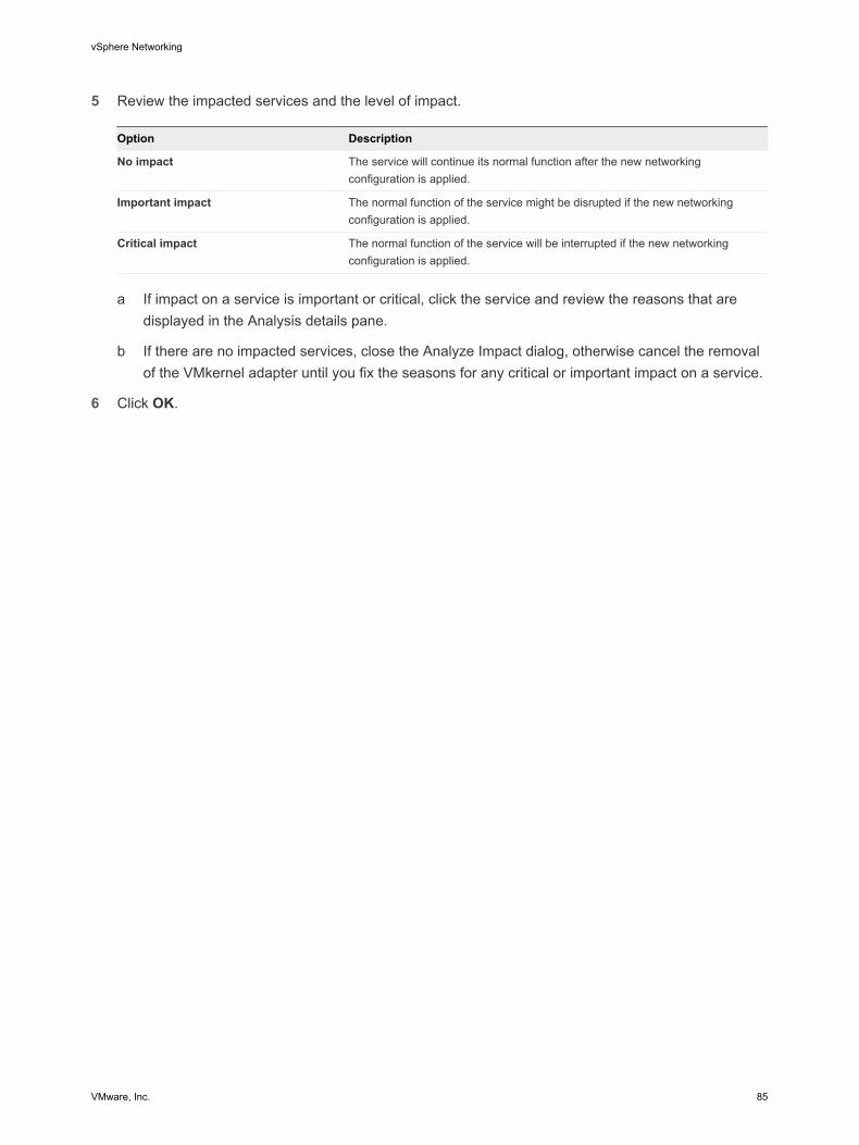
5 Review the impacted services and the level of impact.
Option Description
No impact The service will continue its normal function after the new networkingconfiguration is applied.
Important impact The normal function of the service might be disrupted if the new networkingconfiguration is applied.
Critical impact The normal function of the service will be interrupted if the new networkingconfiguration is applied.
a If impact on a service is important or critical, click the service and review the reasons that are
displayed in the Analysis details pane.
b If there are no impacted services, close the Analyze Impact dialog, otherwise cancel the removalof the VMkernel adapter until you fix the seasons for any critical or important impact on a service.
6 Click OK.
vSphere Networking
VMware, Inc. 85

Networking Policies 5Policies set at the standard switch or distributed port group level apply to all of the port groups on thestandard switch or to ports in the distributed port group. The exceptions are the configuration options thatare overridden at the standard port group or distributed port level.
n Teaming and Failover Policy
Teaming and failover policy lets you to determine how network traffic is distributed between physicaladapters and how to reroute traffic in the event of adapter failure.
n VLAN Policy
VLAN policies determine how VLANs function across your network environment.
n Security Policy
Networking security policy provides protection of traffic against MAC address impersonation andunwanted port scanning
n Traffic Shaping Policy
A traffic shaping policy is defined by average bandwidth, peak bandwidth, and burst size. You canestablish a traffic shaping policy for each port group and each distributed port or distributed portgroup.
n Resource Allocation Policy
The Resource Allocation policy allows you to associate a distributed port or port group with a user-created network resource pool. This policy provides you with greater control over the bandwidthgiven to the port or port group.
n Monitoring Policy
The monitoring policy enables or disables NetFlow monitoring on a distributed port or port group.
n Traffic Filtering and Marking Policy
In a vSphere distributed switch 5.5 and later, by using the traffic filtering and marking policy, you canprotect the virtual network from unwanted traffic and security attacks or apply a QoS tag to a certaintype of traffic.
n Port Blocking Policies
Port blocking policies allow you to selectively block ports from sending or receiving data.
VMware, Inc. 86

n Manage Policies for Multiple Port Groups on a vSphere Distributed Switch in the vSphere WebClient
You can modify networking policies for multiple port groups on a vSphere Distributed Switch.
Teaming and Failover PolicyTeaming and failover policy lets you to determine how network traffic is distributed between physicaladapters and how to reroute traffic in the event of adapter failure.
You can edit your load balancing and failover policy by configuring the following parameters:
n Load Balancing determines how outgoing traffic is distributed among the network adapters associatedwith a switch or port group.
Note Incoming traffic is controlled by the load balancing policy on the physical switch.
n Failover Detection controls the link status and beacon probing. Beaconing is not supported with guestVLAN tagging.
n Failover Order can be active or standby.
You might lose connectivity when a failover event occurs. This loss causes the MAC addresses used byvirtual machines that are associated with standard or distributed switch to appear on a different physicalswitch port than the one they had been on previously. To avoid this problem, put your physical switch inPort Fast or Port Fast trunk mode.
Edit Teaming and Failover Policy for a vSphere Standard Switch inthe vSphere Web ClientUse the teaming and failover policy to determine how network traffic of the virtual machines and VMkerneladapters that are connected to the switch is distributed between physical adapters and how to reroutetraffic in the event of an adapter failure.
Procedure
1 In the vSphere Web Client, navigate to the host.
2 On the Manage tab, click Networking, and select Virtual switches.
3 Select a standard switch from the list, click Edit settings and select Teaming and Failover.
vSphere Networking
VMware, Inc. 87

4 From the Load Balancing drop-down menu, specify how the standard or distributed switch selectsan uplink to handle traffic from a virtual machine or VMkernel adapter.
Option Description
Route based on the originating virtualport
Select an uplink based on the virtual port where the traffic entered the virtualswitch.
Route based on IP hash Select an uplink based on a hash of the source and destination IP addresses ofeach packet. For non-IP packets, the switch simply uses the data at those fieldsto compute the hash.
IP-based teaming requires that the physical switch be configured withEtherChannel.
Route based on source MAC hash Select an uplink based on a hash of the source Ethernet.
Route based on physical NIC load Available for distributed port groups or distributed ports. Select an uplink basedon the current load of the physical network adapters connected to the port groupor port. If an uplink remains busy at 75% or higher for 30 seconds, the host proxyswitch moves a part of the virtual machine traffic to a physical adapter that hasfree capacity.
Use explicit failover order From the list of active adapters, always use the highest order uplink that passesfailover detection criteria.
5 From the Network Failover Detection drop-down menu, specify the method that the standard or
distributed switch uses for failover detection.
Option Description
Link Status only Relies only on the link status that the network adapter provides. This optiondetects failures, such as removed cables and physical switch power failures.
However, it does not detect configuration errors, such as the following:n Physical switch port that is blocked by spanning tree or is misconfigured to
the wrong VLAN.n Pulled cable that connects a physical switch to another networking devices,
for example, an upstream switch.
Beacon Probing Sends out and listens for beacon probes on all NICs in the team and uses thisinformation, in addition to link status, to determine link failure. ESX/ESXi sendsbeacon packets every second.
Beaconing is most useful with three or more NICs in a team because ESX/ESXican detect failures of a single adapter. If only two NICs are assigned and one ofthem loses connectivity, the switch cannot determine which NIC needs to betaken out of service because both do not receive beacons and as a result allpackets sent to both uplinks. Using at least three NICs in such a team allows forn-2 failures where n is the number of NICs in the team before reaching anambiguous situation.
The NICs must be in an active/active or active/standby configuration because theNICs in an unused state do not participate in beacon probing.
vSphere Networking
VMware, Inc. 88

6 From the Notify Switches drop-down menu, select whether the standard or distributed switch notifiesthe physical switch in case of a failover.
If you select Yes, whenever a virtual NIC is connected to the virtual switch or whenever that virtualNIC’s traffic is routed over a different physical NIC in the team because of a failover event, anotification is sent over the network to update the lookup tables on physical switches. Notifying thephysical switch offers lowest latency when a failover or a migration with vSphere vMotion occurs.
Note Set this option to No if a connected virtual machines is using Microsoft Network LoadBalancing in unicast mode. No issues exist with Network Load Balancing running in multicast mode.
7 From the Failback drop-down menu, determine whether a physical adapter is returned to activestatus after recovering from a failure.
If failback is set to Yes (default), the adapter is returned to active duty immediately upon recovery,displacing the standby adapter that took over its slot, if any.
If failback is set to No to a standard port, a failed adapter is left inactive after recovery until anothercurrently active adapter fails and must be replaced.
8 Specify how the uplinks in a team are used when a failover occurs by configuring the Failover Orderlist.
If you want to use some uplinks but reserve others for emergencies in case the uplinks in use fail, usethe up and down arrow keys to move them into different groups.
Option Description
Active adapters Continue to use the uplink if the network adapter connectivity is up and active.
Standby adapters Use this uplink if one of the active physical adapter is down.
Unused adapters Do not use this uplink.
9 Click OK.
Edit the Teaming and Failover Policy on a Standard Port Group inthe vSphere Web ClientConfigure the teaming and failover policy on a standard port group to determine how network trafficrelated to a group of virtual machines or a VMkernel adapter is distributed between physical adapters andhow to reroute traffic in the event of a physical adapter failure.
Procedure
1 In the vSphere Web Client, navigate to the host.
2 On the Manage tab, click Networking, and select Virtual switches.
3 Select a standard switch from the list.
The topology diagram of the switch appears.
4 In the topology diagram, select the port group and click Edit settings.
vSphere Networking
VMware, Inc. 89

5 On the Teaming and Failover page, to override the teaming and failover properties inherited from thestandard switch, select the check boxes next to the properties that you want to override.
6 From the Load Balancing drop-down menu, specify how the standard or distributed switch selectsan uplink to handle traffic from a virtual machine or VMkernel adapter.
Option Description
Route based on the originating virtualport
Select an uplink based on the virtual port where the traffic entered the virtualswitch.
Route based on IP hash Select an uplink based on a hash of the source and destination IP addresses ofeach packet. For non-IP packets, the switch simply uses the data at those fieldsto compute the hash.
IP-based teaming requires that the physical switch be configured withEtherChannel.
Route based on source MAC hash Select an uplink based on a hash of the source Ethernet.
Route based on physical NIC load Available for distributed port groups or distributed ports. Select an uplink basedon the current load of the physical network adapters connected to the port groupor port. If an uplink remains busy at 75% or higher for 30 seconds, the host proxyswitch moves a part of the virtual machine traffic to a physical adapter that hasfree capacity.
Use explicit failover order From the list of active adapters, always use the highest order uplink that passesfailover detection criteria.
7 From the Network Failover Detection drop-down menu, specify the method that the standard or
distributed switch uses for failover detection.
Option Description
Link Status only Relies only on the link status that the network adapter provides. This optiondetects failures, such as removed cables and physical switch power failures.
However, it does not detect configuration errors, such as the following:n Physical switch port that is blocked by spanning tree or is misconfigured to
the wrong VLAN.n Pulled cable that connects a physical switch to another networking devices,
for example, an upstream switch.
Beacon Probing Sends out and listens for beacon probes on all NICs in the team and uses thisinformation, in addition to link status, to determine link failure. ESX/ESXi sendsbeacon packets every second.
Beaconing is most useful with three or more NICs in a team because ESX/ESXican detect failures of a single adapter. If only two NICs are assigned and one ofthem loses connectivity, the switch cannot determine which NIC needs to betaken out of service because both do not receive beacons and as a result allpackets sent to both uplinks. Using at least three NICs in such a team allows forn-2 failures where n is the number of NICs in the team before reaching anambiguous situation.
The NICs must be in an active/active or active/standby configuration because theNICs in an unused state do not participate in beacon probing.
vSphere Networking
VMware, Inc. 90

8 From the Notify Switches drop-down menu, select whether the standard or distributed switch notifiesthe physical switch in case of a failover.
If you select Yes, whenever a virtual NIC is connected to the virtual switch or whenever that virtualNIC’s traffic is routed over a different physical NIC in the team because of a failover event, anotification is sent over the network to update the lookup tables on physical switches. Notifying thephysical switch offers lowest latency when a failover or a migration with vSphere vMotion occurs.
Note Set this option to No if a connected virtual machines is using Microsoft Network LoadBalancing in unicast mode. No issues exist with Network Load Balancing running in multicast mode.
9 From the Failback drop-down menu, determine whether a physical adapter is returned to activestatus after recovering from a failure.
If failback is set to Yes (default), the adapter is returned to active duty immediately upon recovery,displacing the standby adapter that took over its slot, if any.
If failback is set to No to a standard port, a failed adapter is left inactive after recovery until anothercurrently active adapter fails and must be replaced.
10 Specify how the uplinks in a team are used when a failover occurs by configuring the Failover Orderlist.
If you want to use some uplinks but reserve others for emergencies in case the uplinks in use fail, usethe up and down arrow keys to move them into different groups.
Option Description
Active adapters Continue to use the uplink if the network adapter connectivity is up and active.
Standby adapters Use this uplink if one of the active physical adapter is down.
Unused adapters Do not use this uplink.
11 Click OK.
Edit the Teaming and Failover Policy on a Distributed Port Groupin the vSphere Web ClientThe teaming and failover policy on a distributed port group lets you determine how network traffic of agroup of virtual machines or VMkernel adapters is distributed between the uplink adapters in a vSphereDistributed Switch and how to reroute traffic in the event of an adapter failure.
Procedure
1 In the vSphere Web Client, navigate to the distributed switch.
2 Right-click the distributed switch, and select Manage Distributed Port Groups.
3 Select the Teaming and failover check box and click Next.
4 Select the port group that you want to configure and click Next.
vSphere Networking
VMware, Inc. 91

5 From the Load Balancing drop-down menu, specify how the standard or distributed switch selectsan uplink to handle traffic from a virtual machine or VMkernel adapter.
Option Description
Route based on the originating virtualport
Select an uplink based on the virtual port where the traffic entered the virtualswitch.
Route based on IP hash Select an uplink based on a hash of the source and destination IP addresses ofeach packet. For non-IP packets, the switch simply uses the data at those fieldsto compute the hash.
IP-based teaming requires that the physical switch be configured withEtherChannel.
Route based on source MAC hash Select an uplink based on a hash of the source Ethernet.
Route based on physical NIC load Available for distributed port groups or distributed ports. Select an uplink basedon the current load of the physical network adapters connected to the port groupor port. If an uplink remains busy at 75% or higher for 30 seconds, the host proxyswitch moves a part of the virtual machine traffic to a physical adapter that hasfree capacity.
Use explicit failover order From the list of active adapters, always use the highest order uplink that passesfailover detection criteria.
6 From the Network Failover Detection drop-down menu, specify the method that the standard or
distributed switch uses for failover detection.
Option Description
Link Status only Relies only on the link status that the network adapter provides. This optiondetects failures, such as removed cables and physical switch power failures.
However, it does not detect configuration errors, such as the following:n Physical switch port that is blocked by spanning tree or is misconfigured to
the wrong VLAN.n Pulled cable that connects a physical switch to another networking devices,
for example, an upstream switch.
Beacon Probing Sends out and listens for beacon probes on all NICs in the team and uses thisinformation, in addition to link status, to determine link failure. ESX/ESXi sendsbeacon packets every second.
Beaconing is most useful with three or more NICs in a team because ESX/ESXican detect failures of a single adapter. If only two NICs are assigned and one ofthem loses connectivity, the switch cannot determine which NIC needs to betaken out of service because both do not receive beacons and as a result allpackets sent to both uplinks. Using at least three NICs in such a team allows forn-2 failures where n is the number of NICs in the team before reaching anambiguous situation.
The NICs must be in an active/active or active/standby configuration because theNICs in an unused state do not participate in beacon probing.
vSphere Networking
VMware, Inc. 92

7 From the Notify Switches drop-down menu, select whether the standard or distributed switch notifiesthe physical switch in case of a failover.
If you select Yes, whenever a virtual NIC is connected to the virtual switch or whenever that virtualNIC’s traffic is routed over a different physical NIC in the team because of a failover event, anotification is sent over the network to update the lookup tables on physical switches. Notifying thephysical switch offers lowest latency when a failover or a migration with vSphere vMotion occurs.
Note Set this option to No if a connected virtual machines is using Microsoft Network LoadBalancing in unicast mode. No issues exist with Network Load Balancing running in multicast mode.
8 From the Failback drop-down menu, determine whether a physical adapter is returned to activestatus after recovering from a failure.
If failback is set to Yes (default), the adapter is returned to active duty immediately upon recovery,displacing the standby adapter that took over its slot, if any.
If failback is set to No to a distributed port, a failed adapter is left inactive after recovery only if theassociated virtual machine is running. If the Failback option is No and a virtual machine is poweredoff when all active physical adapters fail and then one of them recovers, after the virtual machine ispowered on, the virtual NIC is connected to the recovered adapter instead of to a standby one.Powering a virtual machine off and then on leads to reconnecting the virtual NIC to a distributed port.The distributed switch considers the port as newly added, and assigns it the default uplink port, thatis, the active uplink adapter.
9 Specify how the uplinks in a team are used when a failover occurs by configuring the Failover Orderlist.
If you want to use some uplinks but reserve others for emergencies in case the uplinks in use fail, usethe up and down arrow keys to move them into different groups.
Option Description
Active adapters Continue to use the uplink if the network adapter connectivity is up and active.
Standby adapters Use this uplink if one of the active physical adapter is down.
Unused adapters Do not use this uplink.
10 Review your settings and click Finish.
Edit Distributed Port Teaming and Failover Policies with thevSphere Web ClientThe teaming and failover policy lets you determine how network traffic is distributed between physicaladapters and how traffic is rerouted in the event of an adapter failure.
Prerequisites
Enable the port-level override option for this policy. See Edit Advanced Distributed Port Group Settingswith the vSphere Web Client.
vSphere Networking
VMware, Inc. 93

Procedure
1 In the vSphere Web Client, navigate to the distributed switch.
2 On the Manage tab, and select Ports.
3 Select a distributed port from the list and click Edit distributed port settings.
4 Click Teaming and failover and select the check box next to the properties that you want to override.
5 From the Load Balancing drop-down menu, specify how the standard or distributed switch selectsan uplink to handle traffic from a virtual machine or VMkernel adapter.
Option Description
Route based on the originating virtualport
Select an uplink based on the virtual port where the traffic entered the virtualswitch.
Route based on IP hash Select an uplink based on a hash of the source and destination IP addresses ofeach packet. For non-IP packets, the switch simply uses the data at those fieldsto compute the hash.
IP-based teaming requires that the physical switch be configured withEtherChannel.
Route based on source MAC hash Select an uplink based on a hash of the source Ethernet.
Route based on physical NIC load Available for distributed port groups or distributed ports. Select an uplink basedon the current load of the physical network adapters connected to the port groupor port. If an uplink remains busy at 75% or higher for 30 seconds, the host proxyswitch moves a part of the virtual machine traffic to a physical adapter that hasfree capacity.
Use explicit failover order From the list of active adapters, always use the highest order uplink that passesfailover detection criteria.
vSphere Networking
VMware, Inc. 94

6 From the Network Failover Detection drop-down menu, specify the method that the standard ordistributed switch uses for failover detection.
Option Description
Link Status only Relies only on the link status that the network adapter provides. This optiondetects failures, such as removed cables and physical switch power failures.
However, it does not detect configuration errors, such as the following:n Physical switch port that is blocked by spanning tree or is misconfigured to
the wrong VLAN.n Pulled cable that connects a physical switch to another networking devices,
for example, an upstream switch.
Beacon Probing Sends out and listens for beacon probes on all NICs in the team and uses thisinformation, in addition to link status, to determine link failure. ESX/ESXi sendsbeacon packets every second.
Beaconing is most useful with three or more NICs in a team because ESX/ESXican detect failures of a single adapter. If only two NICs are assigned and one ofthem loses connectivity, the switch cannot determine which NIC needs to betaken out of service because both do not receive beacons and as a result allpackets sent to both uplinks. Using at least three NICs in such a team allows forn-2 failures where n is the number of NICs in the team before reaching anambiguous situation.
The NICs must be in an active/active or active/standby configuration because theNICs in an unused state do not participate in beacon probing.
7 From the Notify Switches drop-down menu, select whether the standard or distributed switch notifies
the physical switch in case of a failover.
If you select Yes, whenever a virtual NIC is connected to the virtual switch or whenever that virtualNIC’s traffic is routed over a different physical NIC in the team because of a failover event, anotification is sent over the network to update the lookup tables on physical switches. Notifying thephysical switch offers lowest latency when a failover or a migration with vSphere vMotion occurs.
Note Set this option to No if a connected virtual machines is using Microsoft Network LoadBalancing in unicast mode. No issues exist with Network Load Balancing running in multicast mode.
8 From the Failback drop-down menu, determine whether a physical adapter is returned to activestatus after recovering from a failure.
If failback is set to Yes (default), the adapter is returned to active duty immediately upon recovery,displacing the standby adapter that took over its slot, if any.
If failback is set to No to a distributed port, a failed adapter is left inactive after recovery only if theassociated virtual machine is running. If the Failback option is No and a virtual machine is poweredoff when all active physical adapters fail and then one of them recovers, after the virtual machine ispowered on, the virtual NIC is connected to the recovered adapter instead of to a standby one.Powering a virtual machine off and then on leads to reconnecting the virtual NIC to a distributed port.The distributed switch considers the port as newly added, and assigns it the default uplink port, thatis, the active uplink adapter.
vSphere Networking
VMware, Inc. 95

9 Specify how the uplinks in a team are used when a failover occurs by configuring the Failover Orderlist.
If you want to use some uplinks but reserve others for emergencies in case the uplinks in use fail, usethe up and down arrow keys to move them into different groups.
Option Description
Active adapters Continue to use the uplink if the network adapter connectivity is up and active.
Standby adapters Use this uplink if one of the active physical adapter is down.
Unused adapters Do not use this uplink.
10 Click OK.
VLAN PolicyVLAN policies determine how VLANs function across your network environment.
A virtual local area network (VLAN) is a group of hosts with a common set of requirements, whichcommunicate as if they were attached to the same broadcast domain, regardless of their physicallocation. A VLAN has the same attributes as a physical local area network (LAN), but it allows for endstations to be grouped together even if not on the same network switch.
The scope of VLAN policies can be distributed port groups and ports, and uplink port groups and ports.
Edit the VLAN Policy on a Distributed Port Group in thevSphere Web ClientSet the VLAN policy on a distributed port group to apply VLAN tagging globally on all distributed ports .
Procedure
1 Browse to a distributed switch in the vSphere Web Client navigator.
2 Right-click the distributed switch in the navigator and select Manage Distributed Port Groups.
3 Select the VLAN check box and click Next.
4 Select the port group that you want to edit and click Next.
5 Select the type of VLAN traffic filtering and marking from the Type drop-down menu and click Next.
Option Description
None Do not use VLAN.
Use this option in case of External Switch Tagging (EST).
VLAN Tag traffic with the ID from the VLAN ID field.
Type a number between 1 and 4094 for Virtual Switch Tagging (VST). Type 4095for Virtual Guest Tagging (VGT).
vSphere Networking
VMware, Inc. 96

Option Description
VLAN Trunking Pass VLAN traffic with ID within the VLAN trunk range. You can set multipleranges and individual VLANs by using a comma-separated list.
Use this option in VGT.
Private VLAN Associate the traffic with a private VLAN created on the distributed switch.
6 Review your settings and click Finish.
Edit the VLAN Policy on a Distributed Port with thevSphere Web ClientUse the VLAN policy on a distributed port to integrate the virtual traffic through the port with physicalVLANs in a different way from the parent distributed port group.
Prerequisites
To override the VLAN policy at the port level, enable the port-level overrides. See Edit AdvancedDistributed Port Group Settings with the vSphere Web Client
Procedure
1 Browse to a distributed switch in the vSphere Web Client navigator.
2 Click the Manage tab and select Ports.
3 Select a port from the list.
4 Click Edit distributed port settings.
5 Click VLAN and select Override.
Configure VLAN traffic through the distributed port from the VLAN Type drop-down meny.
Option Description
None Do not use VLAN.
Use this option in case of External Switch Tagging (EST).
VLAN Tag traffic with the ID from the VLAN ID field.
Type a number between 1 and 4094 for Virtual Switch Tagging (VST). Type 4095for Virtual Guest Tagging (VGT).
VLAN Trunking Pass VLAN traffic with ID within the VLAN trunk range. You can set multipleranges and individual VLANs by using a comma-separated list.
Use this option in VGT.
Private VLAN Associate the traffic with a private VLAN created on the distributed switch.
6 Click OK.
Edit the VLAN Policy on an Uplink Port Group in thevSphere Web ClientSet the VLAN policy on an uplink port group to configure VLAN traffic processing generally for all memberuplinks.
vSphere Networking
VMware, Inc. 97

Use the VLAN policy at the uplink port level to propagate a trunk range of VLAN IDs to the physicalnetwork adapters for traffic filtering. The physical network adapters drop the packets from the otherVLANs if the adapters support filtering by VLAN. Setting a trunk range improves networking performancebecause physical network adapters filter traffic instead of the uplink ports in the group.
If you have a physical network adapter which does not support VLAN filtering, the VLANs might still notbe blocked. In this case, configure VLAN filtering on a distributed port group or on a distributed port.
See the technical documentation from the adapter vendors for information about VLAN filtering support.
Procedure
1 Locate an uplink port group in the vSphere Web Client.
a To locate an uplink port group, select a distributed switch and click the Related Objects tab.
b Select the Uplink Port Groups tab and locate the uplink group in the list.
2 Right-click the uplink port group in the list and select Edit Settings.
3 Click VLAN and type a VLAN trunk range to propagate to the physical network adapters.
For trunking of several ranges and individual VLANs, separate the entries with commas.
4 Click OK.
Edit the VLAN Policy on an Uplink Port with thevSphere Web ClientSet the VLAN policy on an uplink port to handle VLAN traffic through the port in a different way than forthe parent uplink port group.
Use the VLAN policy at the uplink port to propagate a trunk range of VLAN IDs to the physical networkadapter for traffic filtering. The physical network adapter drops packets from the other VLANs if theadapter supports filtering by VLAN. Setting a trunk range improves networking performance because thephysical network adapter filters traffic instead of the uplink port.
If you have a physical network adapter which does not support VLAN filtering, the VLANs might still notbe blocked. In this case, configure VLAN filtering on a distributed port group or on a distributed port.
See the technical documentation from the adapter vendor for information about VLAN filtering support.
Prerequisites
To override the VLAN policy at the port level, enable the port-level overrides. See Edit AdvancedDistributed Port Group Settings with the vSphere Web Client.
Procedure
1 Locate an uplink port group in the vSphere Web Client.
a To locate an uplink port group, select a distributed switch and click the Related Objects tab.
b Select the Uplink Port Groups tab and double-click an uplink port group from the list.
The uplink port group appears at the top level of the navigator on the left.
vSphere Networking
VMware, Inc. 98

2 Click the Manage tab and select Ports.
3 Select an uplink port from the list and click Edit distributed port settings.
4 Click VLAN and select the Override check box.
5 Type a VLAN trunk range to propagate to the physical network adapter.
For trunking of several ranges and individual VLANs, separate the entries with commas.
6 Click OK.
Security PolicyNetworking security policy provides protection of traffic against MAC address impersonation andunwanted port scanning
The security policy of a standard or distributed switch is implemented in Layer 2 (Data Link Layer) of thenetwork protocol stack. The three elements of the security policy are promiscuous mode, MAC addresschanges, and forged transmits. See the vSphere Security documentation for information about potentialnetworking threats.
Edit Security Policy for a vSphere Standard Switch in thevSphere Web ClientFor a vSphere standard switch you can configure security policy to reject MAC address and promiscuousmode changes in the guest operating system of a virtual machine.
You can configure security policy for an individual standard port group as well.
Procedure
1 In the vSphere Web Client, navigate to the host.
2 On the Manage tab, click Networking, and select Virtual switches.
3 Select a standard switch from the list and click Edit settings.
vSphere Networking
VMware, Inc. 99

4 Select Security, and reject or accept promiscuous mode activation or MAC address changes in theguest operating system of the virtual machines attached to the standard switch.
By default, enabling promiscuous mode and MAC address changes for both inbound and outboundtraffic is not accepted.
Option Description
Promiscuous mode n Reject: Placing an adapter in promiscuous mode from the guest operatingsystem does not result in receiving frames for other virtual machines.
n Accept: If an adapter is placed in promiscuous mode from the guestoperating system, the switch allows the guest adapter to receive all framespassed on the switch in compliance with the active VLAN policy for the port towhich the adapter is connected.
Firewalls, port scanners, intrusion detection systems and so on, need to runin promiscuous mode.
MAC address changes n Reject: If you set the MAC Address Changes to Reject and the guestoperating system changes the MAC address of the adapter to a valuedifferent from the address in the virtual machine configuration file (.vmx), theswitch drops all inbound frames to the virtual machine adapter.
If the guest operating system changes the MAC address back, the virtualmachine receives frames again.
n Accept: If the guest operating system changes the MAC address of anetwork adapter, the switch allows frames to the new address of the adapterto pass.
Forged transmits n Reject: The switch drops any outbound frame from a virtual machine adapterwith a source MAC address that is different from the one in the .vmxconfiguration file.
n Accept: The switch does not perform filtering and permits all outboundframes.
5 Click OK.
Edit the Layer 2 Security Policy Exception for a Standard PortGroup in the vSphere Web ClientBy using the security policy on a port group you can accept or reject promiscuous mode and MACaddress changes in the guest operating system of a virtual machine connected to the group.
Procedure
1 In the vSphere Web Client, navigate to the host.
2 On the Manage tab, click Networking, and select Virtual switches.
3 Select a standard switch from the list.
The topology diagram of the standard switch appears.
4 In the topology diagram of the standard switch, click the name of the standard port group to configure.
5 Click Edit settings.
vSphere Networking
VMware, Inc. 100

6 In the Security section, select the check boxes next to the security policies to override and use thedrop-down menus to configure security over the virtual machine traffic through the ports of the group.
By default, enabling promiscuous mode and MAC address changes for both inbound and outboundtraffic is not accepted.
Option Description
Promiscuous mode n Reject: Placing an adapter in promiscuous mode from the guest operatingsystem does not result in receiving frames for other virtual machines.
n Accept: If an adapter is placed in promiscuous mode from the guestoperating system, the switch allows the guest adapter to receive all framespassed on the switch in compliance with the active VLAN policy for the port towhich the adapter is connected.
Firewalls, port scanners, intrusion detection systems and so on, need to runin promiscuous mode.
MAC address changes n Reject: If you set the MAC Address Changes to Reject and the guestoperating system changes the MAC address of the adapter to a valuedifferent from the address in the virtual machine configuration file (.vmx), theswitch drops all inbound frames to the virtual machine adapter.
If the guest operating system changes the MAC address back, the virtualmachine receives frames again.
n Accept: If the guest operating system changes the MAC address of anetwork adapter, the switch allows frames to the new address of the adapterto pass.
Forged transmits n Reject: The switch drops any outbound frame from a virtual machine adapterwith a source MAC address that is different from the one in the .vmxconfiguration file.
n Accept: The switch does not perform filtering and permits all outboundframes.
7 Click OK.
Edit the Security Policy for a Distributed Port Group in thevSphere Web ClientYou can set a security policy on a distributed port group to allow or reject enabling promiscuous modeand MAC address changes from the guest operating system of a virtual machine associated with the portgroup.
You can configure security policy for an individual distributed port as well.
Procedure
1 Navigate to a distributed switch in the vSphere Web Client .
2 Right-click the distributed switch and select Manage Distributed Port Groups.
3 Click the Security check box and click Next.
4 Select the distributed port group to configure and click Next.
vSphere Networking
VMware, Inc. 101

5 Use the drop-down menus to edit the security settings on the traffic through the ports of the group,and click Next.
By default, enabling promiscuous mode and MAC address changes for both inbound and outboundtraffic is not accepted.
Option Description
Promiscuous mode n Reject: Placing an adapter in promiscuous mode from the guest operatingsystem does not result in receiving frames for other virtual machines.
n Accept: If an adapter is placed in promiscuous mode from the guestoperating system, the switch allows the guest adapter to receive all framespassed on the switch in compliance with the active VLAN policy for the port towhich the adapter is connected.
Firewalls, port scanners, intrusion detection systems and so on, need to runin promiscuous mode.
MAC address changes n Reject: If you set the MAC Address Changes to Reject and the guestoperating system changes the MAC address of the adapter to a valuedifferent from the address in the virtual machine configuration file (.vmx), theswitch drops all inbound frames to the virtual machine adapter.
If the guest operating system changes the MAC address back, the virtualmachine receives frames again.
n Accept: If the guest operating system changes the MAC address of anetwork adapter, the switch allows frames to the new address of the adapterto pass.
Forged transmits n Reject: The switch drops any outbound frame from a virtual machine adapterwith a source MAC address that is different from the one in the .vmxconfiguration file.
n Accept: The switch does not perform filtering and permits all outboundframes.
6 Review your settings and click Finish.
Edit Distributed Port Security Policies with thevSphere Web ClientOn a distributed port you can override the policy inherited from the distributed port group to accept orreject enabling promiscuous mode and MAC address changes in the guest operating system of the virtualmachine connected to the port.
Prerequisites
Enable port-level overrides. See Edit Advanced Distributed Port Group Settings with the vSphere WebClient
Procedure
1 Navigate to a distributed switch in the vSphere Web Client.
2 Click the Manage tab, and select Ports.
3 Select a port from the list.
vSphere Networking
VMware, Inc. 102

4 Click Edit distributed port settings.
5 Click Security and select the check box for the settings you want to override for the traffic through theport.
By default, enabling promiscuous mode and MAC address changes for both inbound and outboundtraffic is not accepted.
Option Description
Promiscuous mode n Reject: Placing an adapter in promiscuous mode from the guest operatingsystem does not result in receiving frames for other virtual machines.
n Accept: If an adapter is placed in promiscuous mode from the guestoperating system, the switch allows the guest adapter to receive all framespassed on the switch in compliance with the active VLAN policy for the port towhich the adapter is connected.
Firewalls, port scanners, intrusion detection systems and so on, need to runin promiscuous mode.
MAC address changes n Reject: If you set the MAC Address Changes to Reject and the guestoperating system changes the MAC address of the adapter to a valuedifferent from the address in the virtual machine configuration file (.vmx), theswitch drops all inbound frames to the virtual machine adapter.
If the guest operating system changes the MAC address back, the virtualmachine receives frames again.
n Accept: If the guest operating system changes the MAC address of anetwork adapter, the switch allows frames to the new address of the adapterto pass.
Forged transmits n Reject: The switch drops any outbound frame from a virtual machine adapterwith a source MAC address that is different from the one in the .vmxconfiguration file.
n Accept: The switch does not perform filtering and permits all outboundframes.
6 Click OK.
Traffic Shaping PolicyA traffic shaping policy is defined by average bandwidth, peak bandwidth, and burst size. You canestablish a traffic shaping policy for each port group and each distributed port or distributed port group.
vSphere Networking
VMware, Inc. 103

ESXi shapes outbound network traffic on standard switches and inbound and outbound traffic ondistributed switches. Traffic shaping restricts the network bandwidth available on a port, but can also beconfigured to allow bursts of traffic to flow through at higher speeds.
Average Bandwidth Establishes the number of bits per second to allow across a port, averagedover time. This number is the allowed average load.
Peak Bandwidth Maximum number of bits per second to allow across a port when it issending or receiving a burst of traffic. This number limits the bandwidth thata port uses when it is using its burst bonus.
Burst Size Maximum number of bytes to allow in a burst. If this parameter is set, a portmight gain a burst bonus if it does not use all its allocated bandwidth. Whenthe port needs more bandwidth than specified by the average bandwidth, itmight be allowed to temporarily transmit data at a higher speed if a burstbonus is available. This parameter limits the number of bytes that haveaccumulated in the burst bonus and transfers traffic at a higher speed.
Edit the Traffic Shaping Policy for a vSphere Standard Switch inthe vSphere Web ClientESXi lets you to shape outbound traffic on standard switches. The traffic shaper restricts the networkbandwidth available to any port, but you can also configure it to temporarily allow bursts of traffic to flowthrough a port at higher speeds.
A traffic shaping policy is defined by three characteristics: average bandwidth, peak bandwidth, and burstsize.
Average Bandwidth Establishes the number of bits per second to allow across a port, averagedover time (the allowed average load).
Peak Bandwidth The maximum number of bits per second to allow across a port when it issending a burst of traffic. This tops the bandwidth used by a port wheneverit is using its burst bonus. This parameter can never be smaller than theaverage bandwidth.
Burst Size The maximum number of bytes to allow in a burst. If this parameter is set, aport might gain a burst bonus when it does not use all its allocatedbandwidth. Whenever the port needs more bandwidth than specified byAverage Bandwidth, it might be allowed to temporarily transmit data at ahigher speed if a burst bonus is available. This parameter tops the numberof bytes that can be accumulated in the burst bonus and transferred at ahigher speed.
Procedure
1 In the vSphere Web Client, navigate to the host.
2 On the Manage tab, click Networking, and select Virtual switches.
vSphere Networking
VMware, Inc. 104

3 Select a standard switch from the list and click Edit settings.
4 Click Traffic shaping and enable or disable traffic shaping policy exceptions with the Status drop-down menu.
The Status policy is applied to each VMkernel adapter or virtual machine network adapter attached tothe port group, not to the standard switch as a whole. If you enable the traffic policy exception, youset limits on the amount of networking bandwidth allocation for each VMkernel adapter of virtualmachine network adapter associated with this particular port group. If you disable the policy, serviceshave a clear connection to the physical network by default.
5 For each traffic shaping policy (Average Bandwidth, Peak Bandwidth, and Burst Size), enter abandwidth value.
6 Click OK.
Edit the Traffic Shaping Policy for a Standard Port Group in thevSphere Web ClientUse traffic shaping policies to control the bandwidth and burst size on a port group.
Procedure
1 Browse to a host in the vSphere Web Client navigator.
2 Click the Manage tab, and click Networking > Virtual Switches.
3 Select a standard switch from the list.
A topology diagram of the standard switch infrastructure appears.
4 Select a port group and click Edit settings above the diagram.
5 Click Traffic Shaping and click the Override check box to override the traffic shaping policy at thestandard port group level and enter settings.
Option Description
Status If you enable the policy exception in the Status field, you are setting limits on theamount of networking bandwidth allocated for each virtual adapter associatedwith this particular port group. If you disable the policy, services have a free andclear connection to the physical network.
Average Bandwidth A value measured over a particular period of time.
Peak Bandwidth Limits the maximum bandwidth during a burst. It can never be smaller than theaverage bandwidth.
Burst Size Specifies how large a burst can be in kilobytes (KB).
6 Click OK.
vSphere Networking
VMware, Inc. 105
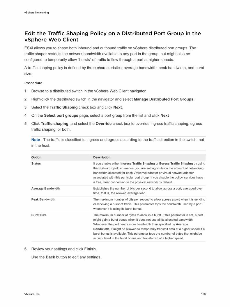
Edit the Traffic Shaping Policy on a Distributed Port Group in thevSphere Web ClientESXi allows you to shape both inbound and outbound traffic on vSphere distributed port groups. Thetraffic shaper restricts the network bandwidth available to any port in the group, but might also beconfigured to temporarily allow “bursts” of traffic to flow through a port at higher speeds.
A traffic shaping policy is defined by three characteristics: average bandwidth, peak bandwidth, and burstsize.
Procedure
1 Browse to a distributed switch in the vSphere Web Client navigator.
2 Right-click the distributed switch in the navigator and select Manage Distributed Port Groups.
3 Select the Traffic Shaping check box and click Next.
4 On the Select port groups page, select a port group from the list and click Next
5 Click Traffic shaping, and select the Override check box to override ingress traffic shaping, egresstraffic shaping, or both.
Note The traffic is classified to ingress and egress according to the traffic direction in the switch, notin the host.
Option Description
Status If you enable either Ingress Traffic Shaping or Egress Traffic Shaping by usingthe Status drop-down menus, you are setting limits on the amount of networkingbandwidth allocated for each VMkernel adapter or virtual network adapterassociated with this particular port group. If you disable the policy, services havea free, clear connection to the physical network by default.
Average Bandwidth Establishes the number of bits per second to allow across a port, averaged overtime, that is, the allowed average load.
Peak Bandwidth The maximum number of bits per second to allow across a port when it is sendingor receiving a burst of traffic. This parameter tops the bandwidth used by a portwhenever it is using its burst bonus.
Burst Size The maximum number of bytes to allow in a burst. If this parameter is set, a portmight gain a burst bonus when it does not use all its allocated bandwidth.Whenever the port needs more bandwidth than specified by AverageBandwidth, it might be allowed to temporarily transmit data at a higher speed if aburst bonus is available. This parameter tops the number of bytes that might beaccumulated in the burst bonus and transferred at a higher speed.
6 Review your settings and click Finish.
Use the Back button to edit any settings.
vSphere Networking
VMware, Inc. 106

Edit the Traffic Shaping Policy on a Distributed Port in thevSphere Web ClientESXi allows you to shape both inbound and outbound traffic on vSphere distributed switches. The trafficshaper restricts the network bandwidth available to a port, but might also be configured to temporarilyallow bursts of traffic to flow through the port at higher speeds.
A traffic shaping policy is defined by three characteristics: average bandwidth, peak bandwidth, and burstsize.
Prerequisites
Enable the port-level override option for this policy. See Edit Advanced Distributed Port Group Settingswith the vSphere Web Client.
Procedure
1 Browse to a distributed switch in the vSphere Web Client.
2 To navigate to the distributed ports of the distributed switch, click Manage > Ports.
3 Select a port from the list.
4 Click Edit distributed port settings.
5 Click Traffic shaping, and select the Override check box to override ingress traffic shaping, egresstraffic shaping, or both.
Note The traffic is classified to ingress and egress according to the traffic direction in the switch, notin the host.
Option Description
Status If you enable either Ingress Traffic Shaping or Egress Traffic Shaping by usingthe Status drop-down menus, you are setting limits on the amount of networkingbandwidth allocated for each VMkernel adapter or virtual network adapterassociated with this particular port group. If you disable the policy, services havea free, clear connection to the physical network by default.
Average Bandwidth Establishes the number of bits per second to allow across a port, averaged overtime, that is, the allowed average load.
Peak Bandwidth The maximum number of bits per second to allow across a port when it is sendingor receiving a burst of traffic. This parameter tops the bandwidth used by a portwhenever it is using its burst bonus.
Burst Size The maximum number of bytes to allow in a burst. If this parameter is set, a portmight gain a burst bonus when it does not use all its allocated bandwidth.Whenever the port needs more bandwidth than specified by AverageBandwidth, it might be allowed to temporarily transmit data at a higher speed if aburst bonus is available. This parameter tops the number of bytes that might beaccumulated in the burst bonus and transferred at a higher speed.
vSphere Networking
VMware, Inc. 107

6 Review your settings in the Ready to complete section and click Finish.
Use the Back button to edit any settings.
Resource Allocation PolicyThe Resource Allocation policy allows you to associate a distributed port or port group with a user-created network resource pool. This policy provides you with greater control over the bandwidth given tothe port or port group.
For information about creating and configuring network resource pools, see vSphere Network I/O Control.
Edit the Resource Allocation Policy on a Distributed Port Group inthe vSphere Web ClientAssociate a distributed port group with a network resource pool to give you greater control over thebandwidth that is given to the distributed port group.
Prerequisites
Create one or more user-defined network resource pools. See Create a Network Resource Pool with thevSphere Web Client
Procedure
1 Browse to a distributed switch in the vSphere Web Client navigator.
2 Right-click the distributed switch in the navigator and select Manage Distributed Port Groups.
3 Select the Resource allocation check box and click Next.
4 Select the distributed port group to edit and click Next.
5 Add or remove the distributed port group from the network resource pool and click Next.
n To add the distributed port group, select a user-defined resource pool from the Networkresource pool drop-down menu.
n To remove the distributed port group, select default from the Network resource pool drop-downmenu.
6 Review your settings in the Ready to complete section and click Finish.
Use the Back button to change any settings.
Edit the Resource Allocation Policy on a Distributed Port in thevSphere Web ClientAssociate a distributed port with a network resource pool to give you greater control over the bandwidthgiven to the port.
vSphere Networking
VMware, Inc. 108
Prerequisites
n Create one or more user-defined network resource pools. See Create a Network Resource Pool withthe vSphere Web Client
n Enable port-level overrides. See Edit Advanced Distributed Port Group Settings with the vSphereWeb Client.
Procedure
1 Browse to a distributed switch in the vSphere Web Client navigator.
2 Click the Manage tab and click Ports.
3 Select a port from the list and click Edit distributed port settings.
4 In the Properties section, click the Override check box and add or remove the port from a networkresource pool.
If you did not enable port-level overrides, the options are not available.
n To add the distributed port to a resource pool, select a user-defined resource pool from theNetwork resource pool drop-down menu.
n To remove the distributed port from a resource pool, select Default from the Network resourcepool drop-down menu.
5 Click OK.
Monitoring PolicyThe monitoring policy enables or disables NetFlow monitoring on a distributed port or port group.
NetFlow settings are configured at the vSphere distributed switch level. See Configure NetFlow Settingswith the vSphere Web Client.
Edit the Monitoring Policy on a Distributed Port Group in thevSphere Web ClientWith the Monitoring policy, you can enable or disable NetFlow monitoring on a distributed port group.
Procedure
1 Browse to a distributed switch in the vSphere Web Client navigator.
2 Right-click the distributed switch in the object navigator and select Manage Distributed PortGroups.
3 Select the Monitoring check box and click Next.
4 Select the distributed port group to edit and click Next.
vSphere Networking
VMware, Inc. 109

5 Use the drop-menu to enable or disable NetFlow and click Next.
Option Description
Disabled NetFlow is disabled on the distributed port group.
Enabled NetFlow is enabled on the distributed port group. You can configure NetFlowsettings at the vSphere distributed switch level. See Configure NetFlow Settingswith the vSphere Web Client.
6 Review your settings and click Finish.
Use the Back button to change any settings.
Edit the Monitoring Policy on a Distributed Port in thevSphere Web ClientWith the Monitoring policy, you can enable or disable NetFlow monitoring on a distributed port.
Prerequisites
To override the monitoring policy at the port level, enable the port-level overrides. See Edit AdvancedDistributed Port Group Settings with the vSphere Web Client
Procedure
1 Browse to a distributed switch in the vSphere Web Client navigator.
2 Click the Manage tab, and click Ports.
3 Select a port from the list.
Detailed port setting information appears at the bottom of the screen.
4 Click Edit distributed port settings.
5 Click Monitoring and click the check box to override the NetFlow settings at the port group level.
6 Enable or disable Netflow from the drop-down menu.
Note If you have no enabled port-level overrides, the options are not available.
Option Description
Disabled NetFlow is disabled on the distributed port group.
Enabled NetFlow is enabled on the distributed port group. You can configure NetFlowsettings at the vSphere distributed switch level. See Configure NetFlow Settingswith the vSphere Web Client.
7 Click OK.
vSphere Networking
VMware, Inc. 110

Traffic Filtering and Marking PolicyIn a vSphere distributed switch 5.5 and later, by using the traffic filtering and marking policy, you canprotect the virtual network from unwanted traffic and security attacks or apply a QoS tag to a certain typeof traffic.
The traffic filtering and marking policy represents an ordered set of network traffic rules for security andfor QoS tagging of the data flow through the ports of a distributed switch. In general, a rule consists of aqualifier for traffic, and of an action for restricting or prioritizing the matching traffic.
The vSphere distributed switch applies rules on traffic at different places in the data stream. Thedistributed switch applies traffic filter rules on the data path between the virtual machine network adapterand distributed port, or between the uplink port and physical network adapter for rules on uplinks.
Traffic Filtering and Marking on a Distributed Port Group or UplinkPort Group in the vSphere Web ClientSet traffic rules at the level of distributed port groups or of uplink port groups to introduce filtering andpriority tagging for traffic access over virtual machines, VMkernel adapters, or physical adapters.
n Enable Traffic Filtering and Marking on a Distributed Port Group or Uplink Port Group in the vSphereWeb Client
Enable the traffic filtering and marking policy on a port group if you want to configure traffic securityand marking on all virtual machine network adapters or uplink adapters that are participating in thegroup.
n Mark Traffic on a Distributed Port Group or Uplink Port Group in the vSphere Web Client
Assign priority tags to traffic, such as VoIP and streaming video, that has higher networkingrequirements for bandwidth, low latency, and so on. You can mark the traffic with a CoS tag in Layer2 of the network protocol stack or with a DSCP tag in Layer 3.
n Filter Traffic on a Distributed Port Group or Uplink Port Group in the vSphere Web Client
Allow or stop traffic for securing the data that flows through the ports of a distributed port group oruplink port group.
n Working with Network Traffic Rules on a Distributed Port Group or Uplink Port Group in the vSphereWeb Client
Define traffic rules in a distributed port group or uplink port group to introduce a policy for processingtraffic related to virtual machines or to physical adapters. You can filter specific traffic or describe itsQoS demands.
n Disable Traffic Filtering and Marking on a Distributed Port Group or Uplink Port Group in thevSphere Web Client
Let traffic flow to virtual machines or physical adapters without additional control related to securityor QoS by disabling the traffic filtering and marking policy.
vSphere Networking
VMware, Inc. 111

Enable Traffic Filtering and Marking on a Distributed Port Group or UplinkPort Group in the vSphere Web ClientEnable the traffic filtering and marking policy on a port group if you want to configure traffic security andmarking on all virtual machine network adapters or uplink adapters that are participating in the group.
Note You can disable the traffic filtering and marking policy on a particular port to avoid processing thetraffic flowing through the port. See Disable Traffic Filtering and Marking on a Distributed Port or UplinkPort in the vSphere Web Client.
Procedure
1 Locate a distributed port group or an uplink port group in the vSphere Web Client.
a Select a distributed switch and click the Related Objects tab.
b Click Distributed Port Groups to see the list of distributed port groups, or click Uplink PortGroups to see the list of uplink port groups.
2 Right-click the port group and select Edit settings.
3 Select Traffic filtering and marking.
4 From the Status drop-down menu, select Enabled.
5 Click OK.
What to do next
Set up traffic marking or filtering on the data that is flowing through the ports of the distributed port groupor through the uplink port group. See Mark Traffic on a Distributed Port Group or Uplink Port Group in thevSphere Web Client and Filter Traffic on a Distributed Port Group or Uplink Port Group in the vSphereWeb Client.
Mark Traffic on a Distributed Port Group or Uplink Port Group in thevSphere Web ClientAssign priority tags to traffic, such as VoIP and streaming video, that has higher networking requirementsfor bandwidth, low latency, and so on. You can mark the traffic with a CoS tag in Layer 2 of the networkprotocol stack or with a DSCP tag in Layer 3.
Priority tagging is a mechanism to mark traffic that has higher QoS demands. In this way, the network canrecognize different classes of traffic. The network devices can handle the traffic from each classaccording to its priority and requirements.
You can also re-tag traffic to either raise or lower the importance of the flow. By using a low QoS tag, youcan restrict data tagged in a guest operating system.
vSphere Networking
VMware, Inc. 112

Procedure
1 Locate a distributed port group or an uplink port group in the vSphere Web Client.
a Select a distributed switch and click the Related Objects tab.
b Click Distributed Port Groups to see the list of distributed port groups, or click Uplink PortGroups to see the list of uplink port groups.
2 Right-click the port group and select Edit settings.
3 Select Traffic filtering and marking.
4 If traffic filtering and marking is disabled, enable it from the Status drop-down menu.
5 Click New to create a new rule, or select a rule and click Edit to edit it.
6 In the network traffic rule dialog box, select the Tag option from the Action drop-down menu.
7 Set the priority tag for the traffic within the scope of the rule.
Option Description
CoS value Mark the traffic matching the rule with a CoS priority tag in network Layer 2.Select Update CoS tag and type a value from 0 to 7.
DSCP value Mark the traffic associated with the rule with a DSCP tag in network Layer 3.Select Update DSCP value and type a value from 0 to 63.
vSphere Networking
VMware, Inc. 113

8 Specify the kind of traffic that the rule is applicable to.
To determine if a data flow is in the scope of a rule for marking or filtering, the vSphere distributedswitch examines the direction of the traffic, and properties like source and destination, VLAN, nextlevel protocol, infrastructure traffic type, and so on.
a From the Traffic direction drop-down menu, select whether the traffic must be ingress, egress,or both so that the rule recognizes it as matching.
The direction also influences how you are going to identify the traffic source and destination.
b By using qualifiers for system data type, Layer 2 packet attributes, and Layer 3 packet attributesset the properties that packets must have to match the rule.
A qualifier represents a set of matching criteria related to a networking layer. You can matchtraffic to system data type, Layer 2 traffic properties, and Layer 3 traffic properties. You can usethe qualifier for a specific networking layer or can combine qualifiers to match packets moreprecisely.
n Use the system traffic qualifier to match packets to the type of virtual infrastructure data thatis flowing through the ports of the group . For example, you can select NFS for data transfersto network storage.
n Use the MAC traffic qualifier to match packets by MAC address, VLAN ID, and next levelprotocol.
Locating traffic with a VLAN ID on a distributed port group works with Virtual Guest Tagging(VGT). To match traffic to VLAN ID if Virtual Switch Tagging (VST) is active, use a rule on anuplink port group or uplink port.
n Use the IP traffic qualifier to match packets by IP version, IP address, and next level protocoland port.
9 In the rule dialog box, click OK to save the rule.
Example: Voice over IP Traffic Marking
Voice over IP (VoIP) flows have special requirements for QoS in terms of low loss and delay. The trafficrelated to the Session Initiation Protocol (SIP) for VoIP usually has a DSCP tag equal to 26, which standsfor Assured Forwarding Class 3 with Low Drop Probability (AF31).
For example, to mark outgoing SIP UDP packets to a subnet 192.168.2.0/24, you can use the followingrule:
Rule Parameter Parameter Value
Action Tag
DSCP value 26
Traffic direction Egress
Traffic qualifiers IP Qualifier
Protocol UDP
vSphere Networking
VMware, Inc. 114

Rule Parameter Parameter Value
Destination port 5060
Source address IP address matches 192.168.2.0 with prefix length 24
Filter Traffic on a Distributed Port Group or Uplink Port Group in thevSphere Web ClientAllow or stop traffic for securing the data that flows through the ports of a distributed port group or uplinkport group.
Procedure
1 Locate a distributed port group or an uplink port group in the vSphere Web Client.
a Select a distributed switch and click the Related Objects tab.
b Click Distributed Port Groups to see the list of distributed port groups, or click Uplink PortGroups to see the list of uplink port groups.
2 Right-click the port group and select Edit settings.
3 Select Traffic filtering and marking.
4 If traffic filtering and marking is disabled, enable it from the Status drop-down menu.
5 Click New to create a new rule, or select a rule and click Edit to edit it.
6 In the network traffic rule dialog box, use the Action options to let traffic pass through the ports of thedistributed port group or uplink port group, or to restrict it.
vSphere Networking
VMware, Inc. 115

7 Specify the kind of traffic that the rule is applicable to.
To determine if a data flow is in the scope of a rule for marking or filtering, the vSphere distributedswitch examines the direction of the traffic, and properties like source and destination, VLAN, nextlevel protocol, infrastructure traffic type, and so on.
a From the Traffic direction drop-down menu, select whether the traffic must be ingress, egress,or both so that the rule recognizes it as matching.
The direction also influences how you are going to identify the traffic source and destination.
b By using qualifiers for system data type, Layer 2 packet attributes, and Layer 3 packet attributesset the properties that packets must have to match the rule.
A qualifier represents a set of matching criteria related to a networking layer. You can matchtraffic to system data type, Layer 2 traffic properties, and Layer 3 traffic properties. You can usethe qualifier for a specific networking layer or can combine qualifiers to match packets moreprecisely.
n Use the system traffic qualifier to match packets to the type of virtual infrastructure data thatis flowing through the ports of the group . For example, you can select NFS for data transfersto network storage.
n Use the MAC traffic qualifier to match packets by MAC address, VLAN ID, and next levelprotocol.
Locating traffic with a VLAN ID on a distributed port group works with Virtual Guest Tagging(VGT). To match traffic to VLAN ID if Virtual Switch Tagging (VST) is active, use a rule on anuplink port group or uplink port.
n Use the IP traffic qualifier to match packets by IP version, IP address, and next level protocoland port.
8 In the rule dialog box, click OK to save the rule.
Working with Network Traffic Rules on a Distributed Port Group or UplinkPort Group in the vSphere Web ClientDefine traffic rules in a distributed port group or uplink port group to introduce a policy for processingtraffic related to virtual machines or to physical adapters. You can filter specific traffic or describe its QoSdemands.
Note You can override the rules of the policy for traffic filtering and marking at port level. See Workingwith Network Traffic Rules on a Distributed Port or Uplink Port in the vSphere Web Client.
n View Traffic Rules on a Distributed Port Group or Uplink Group in the vSphere Web Client
View the traffic rules that form the traffic filtering and marking policy of a distributed port group oruplink port group.
vSphere Networking
VMware, Inc. 116

n Edit a Traffic Rule on a Distributed Port Group or Uplink Port Group in the vSphere Web Client
Create or edit traffic rules, and use their parameters to configure a policy for filtering or marking thetraffic on a distributed port group or uplink port group.
n Change Rule Priorities on a Distributed Port Group or Uplink Port Group in the vSphere Web Client
Reorder the rules that form the traffic filtering and marking policy of a distributed port group or uplinkport group to change the sequence of actions for processing traffic.
n Delete a Traffic Rule on a Distributed Port Group or Uplink Port Group in the vSphere Web Client
Delete a traffic rule on a distributed port group or uplink port group to stop processing packetsflowing to virtual machines or physical adapters in a specific way.
View Traffic Rules on a Distributed Port Group or Uplink Group in the vSphere Web Client
View the traffic rules that form the traffic filtering and marking policy of a distributed port group or uplinkport group.
Procedure
1 Locate a distributed port group or an uplink port group in the vSphere Web Client.
a Select a distributed switch and click the Related Objects tab.
b Click Distributed Port Groups to see the list of distributed port groups, or click Uplink PortGroups to see the list of uplink port groups.
2 Right-click the port group and select Edit settings.
3 Select Traffic filtering and marking.
4 If traffic filtering and marking is disabled, enable it from the Status drop-down menu.
5 Examine Action to see if the rule filters traffic (Allow or Deny) or marks traffic (Tag) with special QoSdemands.
6 From the upper list, select the rule for which you want to view the criteria for locating traffic.
The traffic qualifying parameters of the rule appear in the Traffic Qualifiers list.
Edit a Traffic Rule on a Distributed Port Group or Uplink Port Group in thevSphere Web Client
Create or edit traffic rules, and use their parameters to configure a policy for filtering or marking the trafficon a distributed port group or uplink port group.
Procedure
1 Locate a distributed port group or an uplink port group in the vSphere Web Client.
a Select a distributed switch and click the Related Objects tab.
b Click Distributed Port Groups to see the list of distributed port groups, or click Uplink PortGroups to see the list of uplink port groups.
2 Right-click the port group and select Edit settings.
vSphere Networking
VMware, Inc. 117

3 Select Traffic filtering and marking.
4 If traffic filtering and marking is disabled, enable it from the Status drop-down menu.
5 Click New to create a new rule, or select a rule and click Edit to edit it.
What to do next
Name the network traffic rule, and deny, allow, or tag the target traffic.
Change Rule Priorities on a Distributed Port Group or Uplink Port Group in thevSphere Web Client
Reorder the rules that form the traffic filtering and marking policy of a distributed port group or uplink portgroup to change the sequence of actions for processing traffic.
The vSphere distributed switch applies network traffic rules in a strict order. If a packet already satisfies arule, the packet might not be passed to the next rule in the policy.
Procedure
1 Locate a distributed port group or an uplink port group in the vSphere Web Client.
a Select a distributed switch and click the Related Objects tab.
b Click Distributed Port Groups to see the list of distributed port groups, or click Uplink PortGroups to see the list of uplink port groups.
2 Right-click the port group and select Edit settings.
3 Select Traffic filtering and marking.
4 If traffic filtering and marking is disabled, enable it from the Status drop-down menu.
5 Select a rule and use the arrow buttons to change its priority.
6 Click OK to apply the changes.
Delete a Traffic Rule on a Distributed Port Group or Uplink Port Group in thevSphere Web Client
Delete a traffic rule on a distributed port group or uplink port group to stop processing packets flowing tovirtual machines or physical adapters in a specific way.
Procedure
1 Locate a distributed port group or an uplink port group in the vSphere Web Client.
a Select a distributed switch and click the Related Objects tab.
b Click Distributed Port Groups to see the list of distributed port groups, or click Uplink PortGroups to see the list of uplink port groups.
2 Right-click the port group and select Edit settings.
3 Select Traffic filtering and marking.
4 If traffic filtering and marking is disabled, enable it from the Status drop-down menu.
vSphere Networking
VMware, Inc. 118

5 Select the rule and click Delete.
6 Click OK.
Disable Traffic Filtering and Marking on a Distributed Port Group or UplinkPort Group in the vSphere Web ClientLet traffic flow to virtual machines or physical adapters without additional control related to security orQoS by disabling the traffic filtering and marking policy.
Note You can enable and set up the traffic filtering and marking policy on a particular port. See EnableTraffic Filtering and Marking on a Distributed Port or Uplink Port in the vSphere Web Client.
Procedure
1 Locate a distributed port group or an uplink port group in the vSphere Web Client.
a Select a distributed switch and click the Related Objects tab.
b Click Distributed Port Groups to see the list of distributed port groups, or click Uplink PortGroups to see the list of uplink port groups.
2 Right-click the port group and select Edit settings.
3 Select Traffic filtering and marking.
4 From the Status drop-down menu, select Disabled.
5 Click OK.
Traffic Filtering and Marking on a Distributed Port or Uplink Portin the vSphere Web ClientFilter traffic or describe its QoS demands for an individual virtual machine, VMkernel adapter, or physicaladapter by configuring the traffic filtering and marking policy on a distributed port or uplink port.
n Enable Traffic Filtering and Marking on a Distributed Port or Uplink Port in the vSphere Web Client
Enable the traffic filtering and marking policy on a port to configure traffic security and marking on avirtual machine network adapter, VMkernel adapter, or uplink adapter.
n Mark Traffic on a Distributed Port or Uplink Port in the vSphere Web Client
Assign priority tags in a rule for traffic that needs special treatment such as VoIP and streamingvideo. You can mark the traffic for a virtual machine, VMkernel adapter, or physical adapter with aCoS tag in Layer 2 of the network protocol stack or with a DSCP tag in Layer 3.
n Filter Traffic on a Distributed Port or Uplink Port in the vSphere Web Client
By using a rule, permit or stop traffic for securing data flows through a virtual machine, a VMkerneladapter, or a physical adapter.
vSphere Networking
VMware, Inc. 119

n Working with Network Traffic Rules on a Distributed Port or Uplink Port in the vSphere Web Client
Define traffic rules in a distributed port or uplink port group to introduce a policy for processing trafficrelated to a virtual machine or to a physical adapter. You can filter specific traffic or describe its QoSdemands.
n Disable Traffic Filtering and Marking on a Distributed Port or Uplink Port in the vSphere Web Client
Disable the traffic filtering and marking policy on a port to let traffic flow to a virtual machine or aphysical adapter without filtering for security or marking for QoS.
Enable Traffic Filtering and Marking on a Distributed Port or Uplink Port inthe vSphere Web ClientEnable the traffic filtering and marking policy on a port to configure traffic security and marking on a virtualmachine network adapter, VMkernel adapter, or uplink adapter.
Prerequisites
Enable the port-level override option for this policy. See Edit Advanced Distributed Port Group Settingswith the vSphere Web Client.
Procedure
1 Browse to a distributed switch in the vSphere Web Client.
2 Navigate to a distributed port or an uplink port.
n To navigate to the distributed ports of the switch, click Manage > Ports.
n To navigate to the uplink ports of an uplink port group, click Related Objects > Uplink PortGroups, double-click an uplink port group from the list, and select Ports on the Manage tab.
3 Select a port from the list.
4 Click Edit distributed port settings.
5 Select Traffic filtering and marking.
6 Select the Override check box, and from the Status drop-down menu, select Enabled.
7 Click OK.
What to do next
Set up traffic filtering or marking for the data flowing through the distributed port or through the uplink port.See Mark Traffic on a Distributed Port or Uplink Port in the vSphere Web Client and Filter Traffic on aDistributed Port or Uplink Port in the vSphere Web Client.
Mark Traffic on a Distributed Port or Uplink Port in the vSphere Web ClientAssign priority tags in a rule for traffic that needs special treatment such as VoIP and streaming video.You can mark the traffic for a virtual machine, VMkernel adapter, or physical adapter with a CoS tag inLayer 2 of the network protocol stack or with a DSCP tag in Layer 3.
vSphere Networking
VMware, Inc. 120

Priority tagging is a mechanism to mark traffic that has higher QoS demands. In this way, the network canrecognize different classes of traffic. The network devices can handle the traffic from each classaccording to its priority and requirements.
You can also re-tag traffic to either raise or lower the importance of the flow. By using a low QoS tag, youcan restrict data tagged in a guest operating system.
Prerequisites
Enable the port-level override option for this policy. See Edit Advanced Distributed Port Group Settingswith the vSphere Web Client.
Procedure
1 Navigate to a distributed port or an uplink port.
n To navigate to the distributed ports of the switch, click Manage > Ports.
n To navigate to the uplink ports of an uplink port group, click Related Objects > Uplink PortGroups, double-click an uplink port group from the list, and select Ports on the Manage tab.
2 Select a port from the list.
3 Click Edit distributed port settings.
4 If traffic filtering and marking is not enabled at the port level, click Override, and from the Statusdrop-down menu, select Enabled.
5 Click New to create a new rule, or select a rule and click Edit to edit it.
You can change a rule inherited from the distributed port group or uplink port group. In this way, therule becomes unique within the scope of the port.
6 In the network traffic rule dialog box, select the Tag option from the Action drop-down menu.
7 Set the priority tag for the traffic within the scope of the rule.
Option Description
CoS value Mark the traffic matching the rule with a CoS priority tag in network Layer 2.Select Update CoS tag and type a value from 0 to 7.
DSCP value Mark the traffic associated with the rule with a DSCP tag in network Layer 3.Select Update DSCP value and type a value from 0 to 63.
vSphere Networking
VMware, Inc. 121

8 Specify the kind of traffic that the rule is applicable to.
To determine if a data flow is in the scope of a rule for marking or filtering, the vSphere distributedswitch examines the direction of the traffic, and properties like source and destination, VLAN, nextlevel protocol, infrastructure traffic type, and so on.
a From the Traffic direction drop-down menu, select whether the traffic must be ingress, egress,or both so that the rule recognizes it as matching.
The direction also influences how you are going to identify the traffic source and destination.
b By using qualifiers for system data type, Layer 2 packet attributes, and Layer 3 packet attributesset the properties that packets must have to match the rule.
A qualifier represents a set of matching criteria related to a networking layer. You can matchtraffic to system data type, Layer 2 traffic properties, and Layer 3 traffic properties. You can usethe qualifier for a specific networking layer or can combine qualifiers to match packets moreprecisely.
n Use the system traffic qualifier to match packets to the type of virtual infrastructure data thatis flowing through the ports of the group . For example, you can select NFS for data transfersto network storage.
n Use the MAC traffic qualifier to match packets by MAC address, VLAN ID, and next levelprotocol.
Locating traffic with a VLAN ID on a distributed port group works with Virtual Guest Tagging(VGT). To match traffic to VLAN ID if Virtual Switch Tagging (VST) is active, use a rule on anuplink port group or uplink port.
n Use the IP traffic qualifier to match packets by IP version, IP address, and next level protocoland port.
9 In the rule dialog box, click OK to save the rule.
Filter Traffic on a Distributed Port or Uplink Port in the vSphere Web ClientBy using a rule, permit or stop traffic for securing data flows through a virtual machine, a VMkerneladapter, or a physical adapter.
Prerequisites
Enable the port-level override option for this policy. See Edit Advanced Distributed Port Group Settingswith the vSphere Web Client.
Procedure
1 Navigate to a distributed port or an uplink port.
n To navigate to the distributed ports of the switch, click Manage > Ports.
n To navigate to the uplink ports of an uplink port group, click Related Objects > Uplink PortGroups, double-click an uplink port group from the list, and select Ports on the Manage tab.
vSphere Networking
VMware, Inc. 122

2 Select a port from the list.
3 Click Edit distributed port settings.
4 If traffic filtering and marking is not enabled at the port level, click Override, and from the Statusdrop-down menu, select Enabled.
5 Click New to create a new rule, or select a rule and click Edit to edit it.
You can change a rule inherited from the distributed port group or uplink port group. In this way, therule becomes unique within the scope of the port.
6 In the network traffic rule dialog box, select the Allow action to let traffic pass through the distributedport or uplink port, or the Drop action to restrict it.
7 Specify the kind of traffic that the rule is applicable to.
To determine if a data flow is in the scope of a rule for marking or filtering, the vSphere distributedswitch examines the direction of the traffic, and properties like source and destination, VLAN, nextlevel protocol, infrastructure traffic type, and so on.
a From the Traffic direction drop-down menu, select whether the traffic must be ingress, egress,or both so that the rule recognizes it as matching.
The direction also influences how you are going to identify the traffic source and destination.
b By using qualifiers for system data type, Layer 2 packet attributes, and Layer 3 packet attributesset the properties that packets must have to match the rule.
A qualifier represents a set of matching criteria related to a networking layer. You can matchtraffic to system data type, Layer 2 traffic properties, and Layer 3 traffic properties. You can usethe qualifier for a specific networking layer or can combine qualifiers to match packets moreprecisely.
n Use the system traffic qualifier to match packets to the type of virtual infrastructure data thatis flowing through the ports of the group . For example, you can select NFS for data transfersto network storage.
n Use the MAC traffic qualifier to match packets by MAC address, VLAN ID, and next levelprotocol.
Locating traffic with a VLAN ID on a distributed port group works with Virtual Guest Tagging(VGT). To match traffic to VLAN ID if Virtual Switch Tagging (VST) is active, use a rule on anuplink port group or uplink port.
n Use the IP traffic qualifier to match packets by IP version, IP address, and next level protocoland port.
8 In the rule dialog box, click OK to save the rule.
vSphere Networking
VMware, Inc. 123

Working with Network Traffic Rules on a Distributed Port or Uplink Port inthe vSphere Web ClientDefine traffic rules in a distributed port or uplink port group to introduce a policy for processing trafficrelated to a virtual machine or to a physical adapter. You can filter specific traffic or describe its QoSdemands.
n View Traffic Rules on a Distributed Port or Uplink Port in the vSphere Web Client
Review the traffic rules that form the traffic filtering and marking policy of a distributed port or uplinkport.
n Edit a Traffic Rule on a Distributed Port or Uplink Port in the vSphere Web Client
Create or edit traffic rules, and use their parameters to configure a policy for filtering or marking thetraffic on a distributed port or uplink port.
n Change Rule Priorities on a Distributed Port or Uplink Port in the vSphere Web Client
Reorder the rules that form the traffic filtering and marking policy of a distributed port or uplink port tochange the sequence of actions for analyzing traffic for security and QoS.
n Delete a Traffic Rule on a Distributed Port or Uplink Port in the vSphere Web Client
Delete a traffic rule on a distributed port or uplink port to stop filtering or marking certain type ofpackets that are flowing to a virtual machine or a physical adapter.
View Traffic Rules on a Distributed Port or Uplink Port in the vSphere Web Client
Review the traffic rules that form the traffic filtering and marking policy of a distributed port or uplink port.
Prerequisites
Enable the port-level override option for this policy. See Edit Advanced Distributed Port Group Settingswith the vSphere Web Client.
Procedure
1 Navigate to a distributed port or an uplink port.
n To navigate to the distributed ports of the switch, click Manage > Ports.
n To navigate to the uplink ports of an uplink port group, click Related Objects > Uplink PortGroups, double-click an uplink port group from the list, and select Ports on the Manage tab.
2 Select a port from the list.
3 Click Edit distributed port settings.
4 Select Traffic filtering and marking.
5 If traffic filtering and marking is not enabled at the port level, click Override, and from the Statusdrop-down menu, select Enabled.
6 Examine Action to see if the rule filters traffic (Allow or Deny) or marks traffic (Tag) with special QoSdemands.
vSphere Networking
VMware, Inc. 124
7 From the upper list, select the rule for which you want to view the criteria for locating traffic.
The traffic qualifying parameters of the rule appear in the Traffic Qualifiers list.
Edit a Traffic Rule on a Distributed Port or Uplink Port in the vSphere Web Client
Create or edit traffic rules, and use their parameters to configure a policy for filtering or marking the trafficon a distributed port or uplink port.
Prerequisites
Enable the port-level override option for this policy. See Edit Advanced Distributed Port Group Settingswith the vSphere Web Client.
Procedure
1 Navigate to a distributed port or an uplink port.
n To navigate to the distributed ports of the switch, click Manage > Ports.
n To navigate to the uplink ports of an uplink port group, click Related Objects > Uplink PortGroups, double-click an uplink port group from the list, and select Ports on the Manage tab.
2 Select a port from the list.
3 Click Edit distributed port settings.
4 Select Traffic filtering and marking.
5 If traffic filtering and marking is not enabled at the port level, click Override, and from the Statusdrop-down menu, select Enabled.
6 Click New to create a new rule, or select a rule and click Edit to edit it.
You can change a rule inherited from the distributed port group or uplink port group. In this way, therule becomes unique within the scope of the port.
What to do next
Name the network traffic rule, and deny, allow, or tag the target traffic.
Change Rule Priorities on a Distributed Port or Uplink Port in the vSphere Web Client
Reorder the rules that form the traffic filtering and marking policy of a distributed port or uplink port tochange the sequence of actions for analyzing traffic for security and QoS.
The vSphere distributed switch applies network traffic rules in a strict order. If a packet already satisfies arule, the packet might not be passed to the next rule in the policy.
Prerequisites
Enable the port-level override option for this policy. See Edit Advanced Distributed Port Group Settingswith the vSphere Web Client.
vSphere Networking
VMware, Inc. 125

Procedure
1 Navigate to a distributed port or an uplink port.
n To navigate to the distributed ports of the switch, click Manage > Ports.
n To navigate to the uplink ports of an uplink port group, click Related Objects > Uplink PortGroups, double-click an uplink port group from the list, and select Ports on the Manage tab.
2 Select a port from the list.
3 Click Edit distributed port settings.
4 Select Traffic filtering and marking.
5 If traffic filtering and marking is not enabled at the port level, click Override, and from the Statusdrop-down menu, select Enabled.
6 Select a rule and use the arrow buttons to change its priority.
7 Click OK to apply the changes.
Delete a Traffic Rule on a Distributed Port or Uplink Port in the vSphere Web Client
Delete a traffic rule on a distributed port or uplink port to stop filtering or marking certain type of packetsthat are flowing to a virtual machine or a physical adapter.
Prerequisites
Enable the port-level override option for this policy. See Edit Advanced Distributed Port Group Settingswith the vSphere Web Client.
Procedure
1 Navigate to a distributed port or an uplink port.
n To navigate to the distributed ports of the switch, click Manage > Ports.
n To navigate to the uplink ports of an uplink port group, click Related Objects > Uplink PortGroups, double-click an uplink port group from the list, and select Ports on the Manage tab.
2 Select a port from the list.
3 Click Edit distributed port settings.
4 Select Traffic filtering and marking.
5 If traffic filtering and marking is not enabled at the port level, click Override, and from the Statusdrop-down menu, select Enabled.
6 Select the rule and click Delete.
7 Click OK.
vSphere Networking
VMware, Inc. 126

Disable Traffic Filtering and Marking on a Distributed Port or Uplink Port inthe vSphere Web ClientDisable the traffic filtering and marking policy on a port to let traffic flow to a virtual machine or a physicaladapter without filtering for security or marking for QoS.
Prerequisites
Enable the port-level override option for this policy. See Edit Advanced Distributed Port Group Settingswith the vSphere Web Client.
Procedure
1 Navigate to a distributed port or an uplink port.
n To navigate to the distributed ports of the switch, click Manage > Ports.
n To navigate to the uplink ports of an uplink port group, click Related Objects > Uplink PortGroups, double-click an uplink port group from the list, and select Ports on the Manage tab.
2 Select a port from the list.
3 Click Edit distributed port settings.
4 Select Traffic filtering and marking.
5 Click Override, and from the Status drop-down menu, select Disabled.
6 Click OK.
Qualifying Traffic for Filtering and MarkingThe traffic that you want to filter or want to mark with QoS tags can be matched to the type of carriedinfrastructure data, such as data for storage, vCenter Server management, and so on, and to Layer 2 andLayer 3 properties .
To match the traffic in the scope of the rule more precisely, you can combine criteria for system data type,Layer 2 header, and Layer 3 header.
System Traffic QualifierBy using the system traffic qualifier in a rule for port group or port, you can determine whether certainsystem data traffic must be marked with a QoS tag, allowed, or dropped.
System Traffic Type
You can select the type of traffic through the ports of the group that carries system data, that is, traffic formanagement from vCenter Server , storage, VMware vSphere® vMotion®, and vSphere Fault Tolerance.You can mark or filter only a specific traffic type, or for all system data traffic except for a infrastructurefeature. For example, you can mark with a QoS value or filter the traffic for management fromvCenter Server , storage and vMotion, but not the traffic carrying the Fault Tolerance data.
vSphere Networking
VMware, Inc. 127

MAC Traffic QualifierBy using the MAC traffic qualifier in a rule, you can define matching criteria for the Layer 2 (Data LinkLayer) properties of packets such as MAC address, VLAN ID, and next level protocol that consumes theframe payload.
Protocol Type
The Protocol type attribute of the MAC traffic qualifier corresponds to the EtherType field in Ethernetframes. EtherType represents the type of next level protocol that is going to consume the payload of theframe.
You can select a protocol from the drop-down menu or type its hexadecimal number. For example, tocapture traffic for the Link Layer Discovery Protocol (LLDP) protocol, type 88CC.
VLAN ID
You can use the VLAN ID attribute of the MAC traffic qualifier to mark or filter traffic in a particular VLAN.
Note The VLAN ID qualifier on a distributed port group works with Virtual Guest Tagging (VGT).
If a flow is tagged with a VLAN ID through Virtual Switch Tagging (VST), it cannot be located by using thisID in a rule on a distributed port group or distributed port. The reason is that the distributed switch checksthe rule conditions, including the VLAN ID, after the switch has already untagged the traffic. In this case,to match traffic by VLAN ID successfully, you must use a rule on an uplink port group or uplink port.
Source Address
By using the Source Address group of attributes, you can match packets by the source MAC address ornetwork.
You can use a comparison operator to mark or filter packets that have or do not have the specified sourceaddress or network.
You can match the traffic source in several ways.
Table 5‑1. Patterns for Filtering or Marking Traffic by MAC Source Address
Parameters to Match Traffic SourceAddress Comparison Operator Networking Argument Format
MAC address is or is not Type the MAC address for matching. Usecolons to separate the octets in it.
MAC network matches or does not match Type the lowest address in the networkand a wildcard mask. Set zeroes at thepositions of the network bits, and ones forthe host part.
For example, for a MAC network with prefix 05:50:56 that is 23 bits long, set the address as00:50:56:00:00:00 and mask as 00:00:01:ff:ff:ff.
vSphere Networking
VMware, Inc. 128

Destination Address
By using the Destination Address group of attributes, you can match packets to their destination address.The MAC destination address options have the same format as those for the source address.
Comparison Operators
To match traffic in a MAC qualifier more closely to your needs, you can use affirmative comparison ornegation. You can use operators such that all packets except the ones with certain attributes fall in thescope of a rule.
IP Traffic QualifierBy using the IP traffic qualifier in a rule, you can define criteria for matching traffic to the Layer 3 (NetworkLayer) properties such as IP version, IP address, next level protocol, and port.
Protocol
The Protocol attribute of the IP traffic qualifier represents the next level protocol consuming the payloadof the packet. You can select a protocol from the drop-down menu or type its decimal number accordingto RFC 1700.
For the TCP and UDP protocols, you can also match traffic by source and destination ports.
Source Port
By using the Source port attribute, you can match TCP or UDP packets by the source port. Consider thetraffic direction when matching traffic to a source port.
Destination Port
By using the Destination port attribute, you can match TCP or UDP packets by the destination port.Consider the traffic direction when matching traffic to a destination port.
Source Address
By using the Source Address attribute, you can match packets by source address or subnet. Consider thetraffic direction when matching traffic to a source address or network.
You can match traffic source in several ways.
Table 5‑2. Patterns for Filtering or Marking Traffic by IP Source Address
Parameters to Match Traffic SourceAddress Comparison Operator Networking Argument Format
IP version any Select the IP version from the drop-downmenu.
IP address is or is not Type the IP address that you want tomatch.
IP subnet matches or does not match Type the lowest address in the subnet andthe bit length of the subnet prefix.
vSphere Networking
VMware, Inc. 129

Destination Address
Use the Destination Address to match packets by IP address, subnet, or IP version. The destinationaddress has the same format as the one for the source.
Comparison Operators
To match traffic in an IP qualifier more closely to your needs, you can use affirmative comparison ornegation. You can define that all packets fall in the scope of a rule except packets with certain attributes.
Port Blocking PoliciesPort blocking policies allow you to selectively block ports from sending or receiving data.
Edit the Port Blocking Policy for a Distributed Port Group in thevSphere Web ClientYou can configure various distributed port group policies.
Procedure
1 Browse to a distributed switch in the vSphere Web Client navigator.
2 Right-click the distributed switch in the object navigator and select Manage Distributed PortGroups.
3 Select the Miscellaneous check box and click Next.
4 Select a distributed port group to edit and click Next.
5 Use the Block all ports drop-down menu to select Yes or No and click Next.
Selecting Yes shuts down all ports in the port group. This might disrupt the normal network operationsof the hosts or virtual machines using the ports.
6 Review your settings and click Finish.
Use the Back button to change any settings.
Edit Distributed Port or Uplink Port Blocking Policies with thevSphere Web ClientYou can configure distributed port or uplink port blocking policies.
Prerequisites
To override the traffic shaping policy at the port level, enable the port-level overrides. See Edit AdvancedDistributed Port Group Settings with the vSphere Web Client
Procedure
1 Browse to a distributed switch in the vSphere Web Client navigator.
2 Click the Manage tab, and select Ports.
vSphere Networking
VMware, Inc. 130

3 Select a port from the list.
4 Click Edit distributed port settings.
5 In the Miscellaneous section, select the Block Port Override check box and choose Yes or No fromthe drop-down menu.
Yes shuts down all ports in the port group. This might disrupt the normal network operations of thehosts or virtual machines using the ports.
6 Click OK.
Manage Policies for Multiple Port Groups on a vSphereDistributed Switch in the vSphere Web ClientYou can modify networking policies for multiple port groups on a vSphere Distributed Switch.
Prerequisites
Create a vSphere Distributed Switch with one or more port groups.
Procedure
1 Browse to a distributed switch in the vSphere Web Client.
2 Right-click the distributed switch, and select Manage Distributed Port Groups.
3 On the Select port group policies page, select the check box next to the policy categories to modifyand click Next.
Option Description
Security Set MAC address changes, forged transmits, and promiscuous mode for theselected port groups.
Traffic shaping Set the average bandwidth, peak bandwidth, and burst size for inbound andoutbound traffic on the selected port groups.
VLAN Configure how the selected port groups connect to physical VLANs.
Teaming and failover Set load balancing, failover detection, switch notification, and failover order for theselected port groups.
Resource allocation Set network resource pool association for the selected port groups. This option isavailable for vSphere Distributed Switch version 5.0. and later.
Monitoring Enable or disable NetFlow on the selected port groups. This option is available forvSphere Distributed Switch version 5.0.0 and later.
Traffic filtering and marking Configure policy for filtering (allow or drop) and for marking certain types of trafficthrough the ports of selected port groups. This option is available for vSphereDistributed Switch version 5.5 and later .
Miscellaneous Enable or disable port blocking on the selected port groups.
4 On the Select port groups page, select the distributed port group(s) to edit and click Next.
vSphere Networking
VMware, Inc. 131

5 (Optional) On the Security page, use the drop-down menus to edit the security exceptions and clickNext.
Option Description
Promiscuous Mode n Reject. Placing a guest adapter in promiscuous mode has no effect on whichframes are received by the adapter.
n Accept. Placing a guest adapter in promiscuous mode causes it to detect allframes passed on the vSphere Distributed Switch that are allowed under theVLAN policy for the port group that the adapter is connected to.
MAC Address Changes n Reject. If set to Reject and the guest operating system changes the MACaddress of the adapter to anything other than what is in the .vmxconfiguration file, all inbound frames are dropped.
If the Guest OS changes the MAC address back to match the MAC addressin the .vmx configuration file, inbound frames are passed again.
n Accept. Changing the MAC address from the Guest OS has the intendedeffect. Frames to the new MAC address are received.
Forged Transmits n Reject. Any outbound frame with a source MAC address that is different fromthe one currently set on the adapter are dropped.
n Accept. No filtering is performed and all outbound frames are passed.
6 (Optional) On the Traffic shaping page, use the drop-down menus to enable or disable Ingress orEgress traffic shaping and click Next.
Option Description
Status If you enable either Ingress Traffic Shaping or Egress Traffic Shaping, you aresetting limits on the amount of networking bandwidth allocated for each VMkerneladapter or virtual network adapter associated with this port group. If you disablethe policy, services have a free, clear connection to the physical network bydefault.
Average Bandwidth Establishes the number of bits per second to allow across a port, averaged overtime, that is, the allowed average load.
Peak Bandwidth The maximum number of bits per second to allow across a port when it is sendingor receiving a burst of traffic. This maximum number tops the bandwidth used bya port whenever it is using its burst bonus.
Burst Size The maximum number of bytes to allow in a burst. If this parameter is set, a portmight gain a burst bonus when it does not use all its allocated bandwidth.Whenever the port needs more bandwidth than specified by AverageBandwidth, it might be allowed to transmit data at a higher speed if a burst bonusis available. This parameter tops the number of bytes that can be accumulated inthe burst bonus and transferred at a higher speed.
7 (Optional) On the VLAN page, use the drop-down menus to edit the VLAN policy and click Next.
Option Description
None Do not use VLAN.
VLAN In the VLAN ID field, enter a number between 1 and 4094.
VLAN Trunking Enter a VLAN trunk range.
Private VLAN Select an available private VLAN to use.
vSphere Networking
VMware, Inc. 132

8 (Optional) On the Teaming and failover page, use the drop-down menus to edit the settings and clickNext.
Option Description
Load Balancing IP-based teaming requires that the physical switch be configured with etherchannel. For all other options, ether channel should be disabled. Select how tochoose an uplink.n Route based on the originating virtual port. Choose an uplink based on
the virtual port where the traffic entered the distributed switch.n Route based on IP hash. Choose an uplink based on a hash of the source
and destination IP addresses of each packet. For non-IP packets, whatever isat those offsets is used to compute the hash.
n Route based on source MAC hash. Choose an uplink based on a hash ofthe source Ethernet.
n Route based on physical NIC load. Choose an uplink based on the currentloads of physical NICs.
n Use explicit failover order. Always use the highest order uplink, from the listof Active adapters, which passes failover detection criteria.
Network Failover Detection Select the method to use for failover detection.n Link Status only. Relies solely on the link status that the network adapter
provides. This option detects failures, such as cable pulls and physical switchpower failures, but not configuration errors, such as a physical switch portbeing blocked by spanning tree or that is misconfigured to the wrong VLAN orcable pulls on the other side of a physical switch.
n Beacon Probing. Sends out and listens for beacon probes on all NICs in theteam and uses this information, in addition to link status, to determine linkfailure. Do not use beacon probing with IP-hash load balancing.
Notify Switches Select Yes or No to notify switches in the case of failover. Do not use this optionwhen the virtual machines using the port group are using Microsoft Network LoadBalancing in unicast mode.
If you select Yes, whenever a virtual NIC is connected to the distributed switch orwhenever that virtual NIC’s traffic is routed over a different physical NIC in theteam because of a failover event, a notification is sent out over the network toupdate the lookup tables on physical switches. Use this process for the lowestlatency of failover occurrences and migrations with vMotion.
vSphere Networking
VMware, Inc. 133
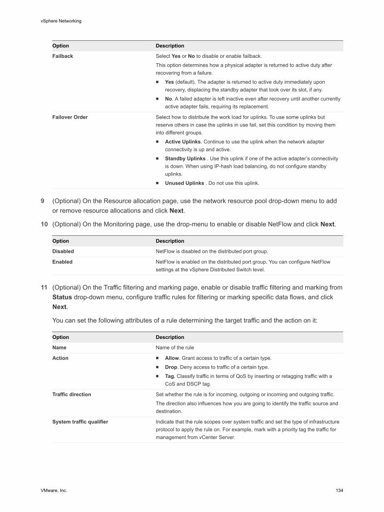
Option Description
Failback Select Yes or No to disable or enable failback.
This option determines how a physical adapter is returned to active duty afterrecovering from a failure.n Yes (default). The adapter is returned to active duty immediately upon
recovery, displacing the standby adapter that took over its slot, if any.n No. A failed adapter is left inactive even after recovery until another currently
active adapter fails, requiring its replacement.
Failover Order Select how to distribute the work load for uplinks. To use some uplinks butreserve others in case the uplinks in use fail, set this condition by moving theminto different groups.n Active Uplinks. Continue to use the uplink when the network adapter
connectivity is up and active.n Standby Uplinks . Use this uplink if one of the active adapter’s connectivity
is down. When using IP-hash load balancing, do not configure standbyuplinks.
n Unused Uplinks . Do not use this uplink.
9 (Optional) On the Resource allocation page, use the network resource pool drop-down menu to addor remove resource allocations and click Next.
10 (Optional) On the Monitoring page, use the drop-menu to enable or disable NetFlow and click Next.
Option Description
Disabled NetFlow is disabled on the distributed port group.
Enabled NetFlow is enabled on the distributed port group. You can configure NetFlowsettings at the vSphere Distributed Switch level.
11 (Optional) On the Traffic filtering and marking page, enable or disable traffic filtering and marking from
Status drop-down menu, configure traffic rules for filtering or marking specific data flows, and clickNext.
You can set the following attributes of a rule determining the target traffic and the action on it:
Option Description
Name Name of the rule
Action n Allow. Grant access to traffic of a certain type.n Drop. Deny access to traffic of a certain type.n Tag. Classify traffic in terms of QoS by inserting or retagging traffic with a
CoS and DSCP tag.
Traffic direction Set whether the rule is for incoming, outgoing or incoming and outgoing traffic.
The direction also influences how you are going to identify the traffic source anddestination.
System traffic qualifier Indicate that the rule scopes over system traffic and set the type of infrastructureprotocol to apply the rule on. For example, mark with a priority tag the traffic formanagement from vCenter Server.
vSphere Networking
VMware, Inc. 134

Option Description
MAC qualifier Qualify the traffic for the rule by Layer 2 header.n Protocol type. Set the next level protocol (IPv4, IPv6, etc.) consuming the
payload.
This attribute corresponds to the EtherType field in Ethernet frames.
You can select a protocol from the drop-down menu or type its hexadecimalnumber
For example, to locate traffic for the Link Layer Discovery Protocol (LLDP)protocol, type 88CC.
n VLAN ID. Locate traffic by VLAN.
The VLAN ID qualifier on a distributed port group works with Virtual GuestTagging (VGT).
If you have a flow tagged with a VLAN ID through Virtual Switch Tagging(VST), you cannot locate the flow by this ID in a distributed port group rule.The reason is that the distributed switch checks the rule conditions, includingthe VLAN ID, after the switch has already untagged the traffic. To matchsuccessfully traffic to a VLAN ID, use a rule for an uplink port group or uplinkport.
n Source Filter. Set a single MAC address or a MAC network to match packetsby source address.
For a MAC network you enter the lowest address in the network and awildcard mask. The mask contains zeroes at the positions of the network bits,and ones for the host part.
For example, for a MAC network with prefix 05:50:56 that is 23 bits long, setthe address as 00:50:56:00:00:00 and the mask as 00:00:01:ff:ff:ff.
n Destination Filter. Set a single MAC address or a MAC network to matchpackets by destination address. The MAC destination address supports thesame format as the source address.
IP qualifier Qualify the traffic for the rule by Layer 3 header.n Protocol. Set the next level protocol (TCP, UDP, etc.) consuming the
payload.
You can select a protocol from the drop-down menu or type its decimalnumber according to RFC 1700, Assigned Numbers.
For TCP and UDP protocol, you can also set source and destination port.n Source port. Match TCP or UDP packets to a source port. Consider the
direction of the traffic that is within the scope of the rule when determining thesource port to match packets to.
n Destination port. Match TCP or UDP packets by the source port. Considerthe direction of the traffic that is within the scope of the rule when determiningthe destination port to match packets to.
n Source Filter. Set the IP version, a single IP address or a subnet to matchpackets by source address.
For a subnet you enter the lowest address and the bit length of the prefix.n Destination Filter. Set the IP version, a single IP address or a subnet to
match packets by source address. The IP destination address supports thesame format as the source address.
vSphere Networking
VMware, Inc. 135

12 (Optional) On the Miscellaneous page, select Yes or No from the drop-down menu and click Next.
SelectYes to shut down all ports in the port group. This shutdown might disrupt the normal networkoperations of the hosts or virtual machines using the ports.
13 Review your settings on the Ready to complete page and click Finish.
Use the Back button to change any settings.
vSphere Networking
VMware, Inc. 136

Managing Network Resources 6vSphere provides several different methods to help you manage your network resources.
This chapter includes the following topics:
n vSphere Network I/O Control
n TCP Segmentation Offload and Jumbo Frames
n NetQueue and Networking Performance
n DirectPath I/O
n Single Root I/O Virtualization (SR-IOV)
vSphere Network I/O ControlNetwork resource pools determine the bandwidth that different network traffic types are given on avSphere distributed switch.
When network I/O control is enabled, distributed switch traffic is divided into the following predefinednetwork resource pools: Fault Tolerance traffic, iSCSI traffic, vMotion traffic, management traffic, vSphereReplication (VR) traffic, NFS traffic, and virtual machine traffic.
You can also create custom network resource pools for virtual machine traffic. You can control thebandwidth each network resource pool is given by setting the physical adapter shares and host limit foreach network resource pool.
The physical adapter shares assigned to a network resource pool determine the share of the totalavailable bandwidth guaranteed to the traffic associated with that network resource pool. The share oftransmit bandwidth available to a network resource pool is determined by the network resource pool'sshares and what other network resource pools are actively transmitting. For example, if you set your FTtraffic and iSCSI traffic resource pools to 100 shares, while each of the other resource pools is set to 50shares, the FT traffic and iSCSI traffic resource pools each receive 25% of the available bandwidth. Theremaining resource pools each receive 12.5% of the available bandwidth. These shares apply only whenthe physical adapter is saturated.
Note The iSCSI traffic resource pool shares do not apply to iSCSI traffic on a dependent hardwareiSCSI adapter.
VMware, Inc. 137

The host limit of a network resource pool is the upper limit of bandwidth that the network resource poolcan use.
Assigning a QoS priority tag to a network resource pool applies an 802.1p tag to all outgoing packetsassociated with that network resource pool.
n Enable Network I/O Control on a vSphere Distributed Switch with the vSphere Web Client
Enable network resource management to use network resource pools to prioritize network traffic bytype.
n Create a Network Resource Pool with the vSphere Web Client
Create user-defined network resource pools for customized network resource management.
n Add or Remove Distributed Port Groups from a Network Resource Pool with the vSphere Web Client
Add a distributed port group to a user-defined network resource pool to include in the networkresource pool all virtual machine network traffic from that distributed port group.
n Edit Network Resource Pool Settings with the vSphere Web Client
You can change both system and user-defined network resource pool settings to change the prioritynetwork traffic for that network resource pool.
n Delete a User-Defined Network Resource Pool with the vSphere Web Client
You can delete user-defined network resource pools that are no longer in use.
Enable Network I/O Control on a vSphere Distributed Switch withthe vSphere Web ClientEnable network resource management to use network resource pools to prioritize network traffic by type.
Prerequisites
Verify that your datacenter has at least one vSphere distributed switch version 4.1.0 or later.
Procedure
1 Browse to a distributed switch in the vSphere Web Client navigator.
2 Click the Manage tab, and select Settings > Properties.
3 Click Edit.
4 Select to Enable or Disable network I/O control from the Network I/O Control drop-down menu.
5 Click OK.
Create a Network Resource Pool with the vSphere Web ClientCreate user-defined network resource pools for customized network resource management.
User-defined network resource pools are available only on vSphere distributed switches version 5.0.0 orlater.
vSphere Networking
VMware, Inc. 138
Procedure
1 Browse to a distributed switch in the vSphere Web Client navigator.
2 Click the Manage tab, and click Resource Allocation.
3 Click New.
4 Type a Name for the network resource pool or accept the generated name.
5 (Optional) Type a Description for the network resource pool.
6 Set the Host limit for the network resource pool in megabits per second, or select Unlimited.
7 Select the Physical adapter shares for the network resource pool from the drop-down menu.
Option Description
Low Sets the shares for this resource pool to 25.
Normal Sets the shares for this resource pool to 50.
High Sets the shares for this resource pool to 100.
Custom Aspecific number of shares, from 1 to 100, for this network resource pool.
8 (Optional) Select the QoS tag for the network resource pool.
The QoS priority tag specifies an IEEE 802.1p tag, allowing quality of service at the media accesscontrol level.
9 Click OK.
The new resource pool appears in the User-defined network resource pools section.
What to do next
Add one or more distributed port groups to the network resource pool.
Add or Remove Distributed Port Groups from a Network ResourcePool with the vSphere Web ClientAdd a distributed port group to a user-defined network resource pool to include in the network resourcepool all virtual machine network traffic from that distributed port group.
Prerequisites
Create one or more user-defined network resource pools on the vSphere distributed switch.
Procedure
1 Browse to a distributed switch in the vSphere Web Client.
2 Right-click the distributed switchin the navitgator and select Manage Distributed Port Groups.
3 On the Select port group policies page, select the Resource allocation check box and click Next.
4 On the Select port groups page, select port groups to edit and click Next.
vSphere Networking
VMware, Inc. 139

5 On the Configure policies - Resource allocation page, add or remove the distributed switch fromthe network resource pool and click Next.
n To add the distributed port group to a resource pool, select a user-defined resource pool from theNetwork resource pool drop-down menu.
n To remove the distributed port group from a resource pool, select default from the Networkresource pool drop-down menu.
Note If there are no user-defined network resource pools on the distributed switch, you will only seedefault in the drop-down menu.
6 Review your settings on the Ready to Complete page and click Finish.
Use the Back button to change your selections.
Edit Network Resource Pool Settings with the vSphere Web ClientYou can change both system and user-defined network resource pool settings to change the prioritynetwork traffic for that network resource pool.
Procedure
1 Browse to a distributed switch in the vSphere Web Client navigator.
2 Click the Manage tab, and click Resource Allocation.
3 Select a network resource pool from the list and click Edit.
4 Edit the Host limit for the network resource pool in megabits per second or select Unlimited.
5 Select an option for the network resource pool from the Physical adapter shares drop-down menu.
Option Description
Low Sets the shares for this resource pool to 25.
Normal Sets the shares for this resource pool to 50.
High Sets the shares for this resource pool to 100.
Custom A specific number of shares, from 1 to 100, for this network resource pool.
6 (Optional) Select a QoS tag for the network resource pool.
The QoS priority tag specifies an IEEE 802.1p tag, allowing quality of service at the media accesscontrol level.
7 Click OK.
Delete a User-Defined Network Resource Pool with thevSphere Web ClientYou can delete user-defined network resource pools that are no longer in use.
Note You cannot delete a system network resource pool.
vSphere Networking
VMware, Inc. 140

Prerequisites
Remove all distributed port groups from the network resource pool.
Procedure
1 Browse to a distributed switch in the vSphere Web Client navigator.
2 Click the Manage tab, and click Resource Allocation.
3 Select a user-defined resource allocation pool and click Remove.
4 Click Yes to delete the resource pool.
TCP Segmentation Offload and Jumbo FramesUsing TCP Segmentation Offload (TSO) in a VMkernel network adapter and virtual machines, and jumboframes on a vSphere distributed switch or vSphere standard switch, improves the network performance invirtual machines and infrastructure workloads.
Enabling TSOUse TCP Segmentation Offload (TSO) in VMkernel network adapters and virtual machines to improve thenetwork performance.
TSO on the transmission path of physical and virtual machine NICs improves the performance ofESX/ESXi hosts by reducing the overhead of the CPU for TCP/IP network operations. When TSO isenabled, the NIC divides larger data chunks into TCP segments instead of the CPU. The host can usemore CPU cycles to run applications.
Enable TSO Support for a Virtual Machine by Using the vSphere Web ClientYou can enable TSO support on a virtual machine by using an enhanced VMXNET adapter for that virtualmachine.
To enable TSO at the virtual machine level, you must replace the existing VMXNET or flexible virtualnetwork adapters with enhanced VMXNET virtual network adapters. This replacement might result in achange in the MAC address of the virtual network adapter.
Prerequisites
To use TSO, verify that the virtual machine runs one of the following guest operating systems:
n Microsoft Windows Server 2003 Enterprise Edition with Service Pack 2 (32 bit and 64 bit) and later
n Red Hat Enterprise Linux 4 (64 bit) and later
n Red Hat Enterprise Linux 5 (32 bit and 64 bit) and later
n SUSE Linux Enterprise Server 10 (32 bit and 64 bit) and later
vSphere Networking
VMware, Inc. 141
Procedure
1 Locate the virtual machine in the vSphere Web Client.
a Select a datacenter, folder, cluster, resource pool, or host and click the Related Objects tab.
b Click Virtual Machines and select the virtual machine from the list.
2 On the Manage tab of the virtual machine, select Settings > VM Hardware.
3 Click Edit and select the Virtual Hardware tab.
4 Expand the network adapter section and write down the network settings and MAC address for thenetwork adapter.
5 Click Remove to remove the network adapter from the virtual machine.
6 From the New device drop-down menu, select Network and click Add.
7 From the Adapter Type drop-down menu, select VMXNET 2 (Enhanced) or VMXNET 3.
8 Set the network setting and MAC address used by the old network adapter.
9 Click OK.
What to do next
If the virtual machine is not set to upgrade VMware Tools each time it is powered on, you must upgradeVMware Tools manually.
Enable TSO Support for a VMkernel Network AdapterWhen using TSO on a VMkernel network adapter, the physical NIC splits large data chunks into TCPsegments instead of the CPU. As a result, the CPU has more cycles for applications. By default, a host isconfigured to use hardware TSO if its NICs support it.
If TSO becomes disabled for a particular VMkernel adapter, the only way you can re-enable TSO is bydeleting the adapter and recreating it with TSO enabled.
Prerequisites
Verify that one of the following requirements are satisfied:
n The VMkernel adapter does not handle traffic related to host networking services, such as iSCSI,vSphere vMotion, and so on.
n The networking services can send traffic by using an alternative VMkernel adapter.
Procedure
1 In the vSphere Web Client, navigate to the host.
2 Under Manage, select Networking and then select VMkernel adapters.
3 Select a VMkernel adapter from the list, and note its settings.
Later you should set the same settings to the newly added VMkernel adapter.
vSphere Networking
VMware, Inc. 142

4 Click Remove.
5 In the confirmation dialog, click Analyze impact, verify that no networking services are impacted, andclick OK.
6 In the VMkernel adapters list, click Add host networking.
7 On the Add connection type page, select VMkernel Network Adapter and click Next.
8 On the Select target device page, assign the VMkernel adapter to a standard switch or distributedport group.
9 On the Port properties page, configure the IP version and networking services related to the oldadapter, and click Next.
10 On the IPv4 Settings and IPv6 Settings pages, configure the IP settings used by the old adapter.
11 Review your settings and click Finish.
Enabling Jumbo FramesJumbo frames let ESXi hosts send larger frames out onto the physical network. The network must supportjumbo frames end-to-end that includes physical network adapters, physical switches, and storagedevices.
Before enabling jumbo frames, check with your hardware vendor to ensure that your physical networkadapter supports jumbo frames.
You can enable jumbo frames on a vSphere distributed switch or vSphere standard switch by changingthe maximum transmission unit (MTU) to a value greater than 1500 bytes. 9000 bytes is the maximumframe size that you can configure.
Enable Jumbo Frames on a vSphere Distributed Switch with thevSphere Web ClientEnable jumbo frames for the entire traffic that passes through a vSphere distributed switch.
Procedure
1 Browse to a distributed switch in the vSphere Web Client navigator.
2 Click the Manage tab, and click Settings > Properties.
3 Click Edit.
4 Click Advanced and set the MTU property to a value greater than 1500 bytes.
You cannot set the MTU size to a value greater than 9000 bytes.
5 Click OK.
Enable Jumbo Frames on a vSphere Standard Switch with thevSphere Web ClientEnable jumbo frames for all traffic through a vSphere standard switch on a host.
vSphere Networking
VMware, Inc. 143

Procedure
1 In the vSphere Web Client, navigate to the host.
2 On the Manage tab, click Networking, and select Virtual switches.
3 Select a standard switch from the virtual switch table and click Edit settings.
4 In the Properties section, set the MTU property to a value greater than 1500 bytes.
You can increase the MTU size up to 9000 bytes.
5 Click OK.
Enable Jumbo Frames for a VMkernel Adapter in the vSphere Web ClientJumbo frames reduce the CPU load caused by transferring data. Enable jumbo frames on a VMkerneladapter by changing the maximum transmission units (MTU) of the adapter.
Procedure
1 In the vSphere Web Client, navigate to the host.
2 Under Manage, select Networking and then select VMkernel adapters.
3 Select a VMkernel adapter from the adapter table.
The properties of the adapter appear.
4 Click the name of the VMkernel adapter.
5 Click Edit.
6 Select NIC settings and set the MTU property to a value greater than 1500.
You can increase the MTU size up to 9000 bytes.
7 Click OK.
Enable Jumbo Frame Support on a Virtual Machine with thevSphere Web ClientEnabling jumbo frame support on a virtual machine requires an enhanced VMXNET adapter for thatvirtual machine.
Procedure
1 Locate the virtual machine in the vSphere Web Client.
a Select a datacenter, folder, cluster, resource pool, or host and click the Related Objects tab.
b Click Virtual Machines and select the virtual machine from the list.
2 On the Manage tab of the virtual machine, select Settings > VM Hardware.
3 Click Edit and select the Virtual Hardware tab.
4 Click the Virtual Hardware section, and expand the network adapter section. Record the networksettings and MAC address that the network adapter is using.
vSphere Networking
VMware, Inc. 144
5 Click Remove to remove the network adapter from the virtual machine.
6 From the New device drop-down menu, select Network and click Add.
7 From the Adapter Type drop-down menu, select VMXNET 2 (Enhanced) or VMXNET 3.
8 Set the network settings to the ones recorded for the old network adapter.
9 Set the MAC Address to Manual, and type the MAC address that the old network adapter was using.
10 Click OK.
What to do next
n Check that the enhanced VMXNET adapter is connected to a standard switch or to a distributedswitch with jumbo frames enabled.
n Inside the guest operating system, configure the network adapter to allow jumbo frames. See thedocumentation of your guest operating system.
n Configure all physical switches and any physical or virtual machines to which this virtual machineconnects to support jumbo frames.
NetQueue and Networking PerformanceNetQueue takes advantage of the ability of some network adapters to deliver network traffic to the systemin multiple receive queues that can be processed separately, allowing processing to be scaled to multipleCPUs, improving receive-side networking performance.
Enable NetQueue on a HostNetQueue is enabled by default. To use NetQueue after it has been disabled, you must reenable it.
Prerequisites
Familiarize yourself with the information on configuring NIC drivers in Getting Started with vSphereCommand-Line Interfaces.
Procedure
1 In the VMware vSphere CLI, use the following command depending on the host version:
ESX/ESXi Version Command
ESX/ESXi 4.x vicfg-advcfg --set true VMkernel.Boot.netNetQueueEnable
ESXi 5.x esxcli system settings kernel set --setting="netNetqueueEnabled" --value="TRUE"
2 Use the VMware vSphere CLI to configure the NIC driver to use NetQueue.
3 Reboot the host.
Disable NetQueue on a HostNetQueue is enabled by default.
vSphere Networking
VMware, Inc. 145

Prerequisites
Familiarize yourself with the information on configuring NIC drivers in Getting Started with vSphereCommand-Line Interfaces.
Procedure
1 In the VMware vSphere CLI, use the following command depending on the host version:
ESX/ESXi version Command
ESX/ESXi 4.x vicfg-advcfg --set false VMkernel.Boot.netNetQueueEnable
ESXi 5.x esxcli system settings kernel set --setting="netNetqueueEnabled" --value="FALSE"
2 To disable NetQueue on the NIC driver, use the vicfg-module -s "" module name command.
For example, if you are using the s2io NIC driver, use vicfg-module -s "" s2io.
3 Reboot the host.
DirectPath I/ODirectPath I/O allows virtual machine access to physical PCI functions on platforms with an I/O MemoryManagement Unit.
The following features are unavailable for virtual machines configured with DirectPath:
n Hot adding and removing of virtual devices
n Suspend and resume
n Record and replay
n Fault tolerance
n High availability
n DRS (limited availability. The virtual machine can be part of a cluster, but cannot migrate acrosshosts)
n Snapshots
Cisco Unified Computing Systems (UCS) through Cisco Virtual Machine Fabric Extender (VM-FEX)distributed switches support the following features for migration and resource management of virtualmachines which use DirectPath I/O:
n vMotion
n Hot adding and removing of virtual devices
n Suspend and resume
n High availability
n DRS
vSphere Networking
VMware, Inc. 146
n Snapshots
See Cisco VM-FEX documentation for details on supported switches and switch configurationinformation.
n Enable Passthrough for a Network Device on a Host in the vSphere Web Client
Passthrough devices provide the means to use resources efficiently and improve performance ofyour environment. You can enable DirectPath I/O passthrough for a network device on a host.
n Configure a PCI Device on a Virtual Machine with the vSphere Web Client
Passthrough devices provide the means to more efficiently use resources and improve performancein your environment. You can configure a passthrough PCI device on a virtual machine in thevSphere Web Client.
n Enable DirectPath I/O with vMotion on a Virtual Machine with the vSphere Web Client
You can enable DirectPath I/O with vMotion for virtual machines in a datacenter on a Cisco UCSsystem that has at least one supported Cisco UCS Virtual Machine Fabric Extender (VM-FEX)distributed switch.
Enable Passthrough for a Network Device on a Host in thevSphere Web ClientPassthrough devices provide the means to use resources efficiently and improve performance of yourenvironment. You can enable DirectPath I/O passthrough for a network device on a host.
Caution If your ESXi host is configured to boot from a USB device or an SD card attached to a USBchannel, make sure that you do not enable DirectPath I/O passthrough for the USB controller. Passingthrough a USB controller on an ESXi host that boots from a USB device or SD card might put the host ina state where its configuration cannot be persisted.
Procedure
1 Browse to a host in the vSphere Web Client navigator.
2 Click the Manage tab, click Settings.
3 In the Hardware section, click PCI Devices.
4 To enable DirectPath I/O passthrough for a PCI network device on the host, click Edit.
A list of available passthrough devices appears.
Icon Description
green icon A device is active and can be enabled.
orange icon The state of the device has changed, and you must reboot the host before you can use the device.
5 Select the network device to be used for passthrough and click OK.
The selected PCI device appears in the table. Device information is displayed at the bottom of thescreen.
vSphere Networking
VMware, Inc. 147
6 Reboot the host to make the PCI network device available for use.
Configure a PCI Device on a Virtual Machine with thevSphere Web ClientPassthrough devices provide the means to more efficiently use resources and improve performance inyour environment. You can configure a passthrough PCI device on a virtual machine in thevSphere Web Client.
Prerequisites
Verify that a passthrough networking device is configured on the host of the virtual machine. See EnablePassthrough for a Network Device on a Host in the vSphere Web Client.
Procedure
1 Locate the virtual machine in the vSphere Web Client.
a Select a datacenter, folder, cluster, resource pool, or host and click the Related Objects tab.
b Click Virtual Machines and select the virtual machine from the list.
2 Power off the virtual machine.
3 On the Manage tab of the virtual machine, select Settings > VM Hardware.
4 Click Edit and select the Virtual Hardware tab.
5 Expand the Memory section, and set the Limit to Unlimited.
6 From the New device drop-down menu select PCI Device and click Add.
7 From the New PCI device drop-down menu select the passthrough device to use, and click OK.
8 Power on the virtual machine.
Adding a DirectPath device to a virtual machine sets memory reservation to the memory size of the virtualmachine.
Enable DirectPath I/O with vMotion on a Virtual Machine with thevSphere Web ClientYou can enable DirectPath I/O with vMotion for virtual machines in a datacenter on a Cisco UCS systemthat has at least one supported Cisco UCS Virtual Machine Fabric Extender (VM-FEX) distributed switch.
Prerequisites
Enable high performance network I/O on at least one Cisco UCS port profile on a supported Cisco VM-FEX distributed switch. For supported switches and switch configuration, see documentation at the CIscoWeb site.http://www.cisco.com/go/unifiedcomputing/b-series-doc
vSphere Networking
VMware, Inc. 148

Procedure
1 Locate the virtual machine in the vSphere Web Client.
a Select a datacenter, folder, cluster, resource pool, or host and click the Related Objects tab.
b Click Virtual Machines and select the virtual machine from the list.
2 Power off the virtual machine.
3 On the Manage tab of the virtual machine, select Settings > VM Hardware.
4 Click Edit and select the Virtual Hardware tab.
5 Expand the Memory section, and set the Limit to Unlimited.
6 Expand the Network adapter section to configure a passthrough device.
7 Select a port profile with high performance enabled from the network drop-down menu and click OK.
8 Power on the virtual machine.
Single Root I/O Virtualization (SR-IOV)vSphere 5.1 and later releases support Single Root I/O Virtualization (SR-IOV). You can use SR-IOV fornetworking of virtual machines that are latency sensitive or require more CPU resources.
Overview of SR-IOVSR-IOV is a specification that allows a single Peripheral Component Interconnect Express (PCIe) physicaldevice under a single root port to appear as multiple separate physical devices to the hypervisor or theguest operating system.
SR-IOV uses physical functions (PFs) and virtual functions (VFs) to manage global functions for the SR-IOV devices. PFs are full PCIe functions that are capable of configuring and managing the SR-IOVfunctionality. It is possible to configure or control PCIe devices using PFs, and the PF has full ability tomove data in and out of the device. VFs are lightweight PCIe functions that support data flowing but havea restricted set of configuration resources.
The number of virtual functions provided to the hypervisor or the guest operating system depends on thedevice. SR-IOV enabled PCIe devices require appropriate BIOS and hardware support, as well as SR-IOV support in the guest operating system driver or hypervisor instance. See SR-IOV Support.
Using SR-IOV in vSphereIn vSphere, a virtual machine can use an SR-IOV virtual function for networking. The virtual machine andthe physical adapter exchange data directly without using the VMkernel as an intermediary. Bypassing theVMkernel for networking reduces latency and improves CPU efficiency.
In vSphere 5.5 and later, though a virtual switch (standard switch or distributed switch) does not handlethe network traffic of an SR-IOV enabled virtual machine connected to the switch, you can control theassigned virtual functions by using switch configuration policies at port group or port level.
vSphere Networking
VMware, Inc. 149

SR-IOV SupportvSphere 5.1 and later supports SR-IOV in an environment with specific configuration only. Some featuresof vSphere are not functional when SR-IOV is enabled.
Supported ConfigurationsTo use SR-IOV in vSphere 5.5, your environment must meet several configuration requirements.
Table 6‑1. Supported Configurations for Using SR-IOV
Component Requirements
vSphere n Hosts with Intel processors require ESXi 5.1 or later.n Hosts with AMD processors are supported with SR-IOV in
ESXi 5.5 or later.
Physical host n Must be compatible with the ESXi release.n Must have an Intel processor if you are running ESXi 5.1, or
an Intel or AMD processor if you are running ESXi 5.5 andlater.
n Must support I/O memory management unit (IOMMU), andmust have IOMMU enabled in the BIOS.
n Must support SR-IOV, and must have SR-IOV enabled in theBIOS. Contact the server vendor to determine whether thehost supports SR-IOV.
Physical NIC n Must be compatible with the ESXi release.n Must be supported for use with the host and SR-IOV
according to the technical documentation from the servervendor.
n Must have SR-IOV enabled in the firmware.
PF driver in ESXi for the physical NIC n Must be certified by VMware.n Must be installed on the ESXi host. The ESXi release
provides a default driver for certain NICs, while for othersyou must download and manually install it.
Guest OS Must be supported by the NIC on the installed ESXi releaseaccording to the technical documentation from the NIC vendor.
VF driver in the guest OS n Must be compatible with the NIC.n Must be supported on the guest OS release according to the
technical documentation from the NIC vendor.n Must be Microsoft WLK or WHCK certified for Windows
virtual machines.n Must be installed on the operating system. The operating
system release contains a default driver for certain NICs,while for others you must download and install it from alocation provided by the vendor of the NIC or the host.
To verify that your physical hosts and NICs are compatible with ESXi releases, see the VMwareCompatibility Guide.
vSphere Networking
VMware, Inc. 150

Availability of FeaturesThe following features are not available for virtual machines configured with SR-IOV:
n vSphere vMotion
n Storage vMotion
n vShield
n NetFlow
n VXLAN Virtual Wire
n vSphere High Availability
n vSphere Fault Tolerance
n vSphere DRS
n vSphere DPM
n Virtual machine suspend and resume
n Virtual machine snapshots
n MAC-based VLAN for passthrough virtual functions
n Hot addition and removal of virtual devices, memory, and vCPU
n Participation in a cluster environment
n Network statistics for a virtual machine NIC using SR-IOV passthrough
Note Attempts to enable or configure unsupported features with SR-IOV in the vSphere Web Clientresult in unexpected behavior in your environment.
Supported NICsAll NICs must have drivers and firmware that support SR-IOV. Some NICs might require SR-IOV to beenabled on the firmware. The following NICs are supported for virtual machines configured with SR-IOV:
n Products based on the Intel 82599ES 10 Gigabit Ethernet Controller Family (Niantic)
n Products based on the Intel Ethernet Controller X540 Family (Twinville)
n Products based on the Intel Ethernet Controller X710 Family (Fortville)
n Products based on the Intel Ethernet Controller XL170 Family (Fortville)
n Emulex OneConnect (BE3)
Upgrading from vSphere 5.0 and EarlierIf you upgrade from vSphere 5.0 or earlier to vSphere 5.5 or later, SR-IOV support is not available untilyou update the NIC drivers for the vSphere release. Firmware and drivers that support SR-IOV must beenabled for NICs so that SR-IOV functionality can operate.
vSphere Networking
VMware, Inc. 151

Upgrading from vSphere 5.1Although SR-IOV is supported on ESXi 5.1 hosts satisfying the requirements, you cannot configure SR-IOV on them by using the vSphere Web Client. Use the max_vfs parameter of the NIC driver module toenable SR-IOV on these hosts. See Enabling SR-IOV by Using Host Profiles in the vSphere Web Clientor Through an ESXCLI Command.
You also cannot assign an SR-IOV passthrough adapter to a virtual machine on such a host. The adapteris available for virtual machines that are compatible with ESXi 5.5 and later. Although a vCenter Server5.5 release might be managing an ESXi 5.1 host, the configuration is the same as in release 5.1. Youmust add a PCI device to the virtual machine hardware and manually select a VF for the device.
SR-IOV Component Architecture and InteractionvSphere SR-IOV support relies on the interaction between the virtual functions (VFs) and the physicalfunction (PF) of the NIC port for better performance, and interaction between the driver of the PF and thehost switch for traffic control.
In a host that runs virtual machine traffic on top of SR-IOV physical adapters, virtual machine adaptersdirectly contact the virtual functions to communicate data. However, the ability to configure networks isbased on the active policies for the port holding the virtual machines.
On an ESXi host without SR-IOV, the virtual switch sends external network traffic through its ports on thehost from or to the physical adapter for the relevant port group. The virtual switch also applies thenetworking policies on managed packets.
vSphere Networking
VMware, Inc. 152

Figure 6‑1. Data and Configuration Paths in the SR-IOV Support of vSphere
VF driver
1
3 4
2 5
VM VM
VF driver
IOMMU
PCI Express
Physical network adapter with SR-IOV
PCI Express
Physical network adapter without SR-IOV
PF
Port group
Uplink port
VMVM
PF
PF driver
Port associationData pathControl path
Port group
Uplink port
VMware ESXi
Virtual Switch Virtual Switch
PF driver
VFVF
Data Path in SR-IOVAfter the virtual machine network adapter is assigned to a virtual function, the VF driver in the guestoperating system uses the I/O memory management unit (IOMMU) technology to access the virtualfunction that must receive or send the data over the network. The VMkernel, that is, the virtual switch inparticular, does not process the data flow, which reduces the overall latency of SR-IOV enabledworkloads.
Configuration Path in SR-IOVIf the guest operating system attempts to change the configuration of a virtual machine adapter mappedto a VF, the change takes place if it is allowed by the policy on the port associated with the virtualmachine adapter.
The configuration workflow consists of the following operations:
1 The guest operating system requests a configuration change on the VF.
vSphere Networking
VMware, Inc. 153

2 The VF forwards the request to the PF through a mailbox mechanism.
3 The PF driver checks the configuration request with the virtual switch (standard switch or host proxyswitch of a distributed switch).
4 The virtual switch verifies the configuration request against the policy on the port with which the VFenabled virtual machine adapter is associated.
5 The PF driver configures the VF if the new settings are in compliance with the port policy of the virtualmachine adapter.
For example, if the VF driver tries to modify the MAC address, the address remains the same if MACaddress change is not allowed in the security policy for the port group or port. The guest operatingsystem might show that the change is successful but a log message indicates that the operation hasfailed. As a result, the guest operating system and the virtual device save different MAC addresses.The network interface in the guest operating system might not be able to acquire an IP address andcommunicate. In this case, you have to reset the interface in the guest operating system to get thelatest MAC address from the virtual device and acquire an IP address.
vSphere and Virtual Function InteractionVirtual functions (VFs) are lightweight PCIe functions that contain all the resources necessary for dataexchange but have a minimized set of configuration resources. Interaction between vSphere and VFs islimited.
n VFs do not implement rate control in vSphere. Every VF can potentially use the entire bandwidth of aphysical link.
n When a VF device is configured as a passthrough device on a virtual machine, the standby andhibernate functions for the virtual machine are not supported.
n The maximum number of VFs that you can create and the maximum number of VFs that you can usefor passthrough are different. The maximum number of VFs that you can instantiate depends on theNIC capability and on the hardware configuration of the host. However, due to the limited number ofinterrupt vectors available for passthrough devices, only a limited number of all instantiated VFs canbe used on an ESXi host.
Each ESXi host has a total of 256 interrupt vectors. When the host boots, devices on the host such asstorage controllers, physical network adapters, and USB controllers consume a subset of the 256vectors. If these devices require more than 128 vectors, the maximum number of potentiallysupported VFs is reduced.
For example, out of 64 VFs that can be instantiated on an Intel NIC, the host can use up to 43 VFs forpassthrough (128 / 3 = 42.6) if all 128 interrupt vectors are available.
vSphere Networking
VMware, Inc. 154

n If you have Intel and Emulex NICs present with SR-IOV enabled, the number of VFs available for theIntel NICs depends on how many VFs are configured for the Emulex NIC, and the reverse. You canuse the following formula to estimate the maximum number of VFs for use if all 128 interrupt vectorsare available for passthrough:
3X + 2Y < 128
where X is the number of Intel VFs, and Y is the number of Emulex VFs.
This number might be smaller if other types of devices on the host use more than 128 interruptvectors from the total of 256 vectors on the host.
n vSphere SR-IOV supports up to 43 VFs on supported Intel NICs and up to 64 VFs on supportedEmulex NICs.
n If a supported Intel NIC loses connection, all VFs from the physical NIC stop communicationcompletely, including that between VFs.
n If a supported Emulex NIC loses connection, all VFs stop communication with the externalenvironment, but communication between VFs still works
n VF drivers offer many different features, such as IPv6 support, TSO, and LRO checksum. See thetechnical documentation of the NIC vendor for more details.
DirectPath I/O vs SR-IOVSR-IOV offers performance benefits and tradeoffs similar to those of DirectPath I/O. DirectPath I/O andSR-IOV have similar functionality but you use them to accomplish different things.
SR-IOV is beneficial in workloads with very high packet rates or very low latency requirements. LikeDirectPath I/O, SR-IOV is not compatible with certain core virtualization features, such as vMotion. SR-IOV does, however, allow for a single physical device to be shared amongst multiple guests.
With DirectPath I/O you can map only one physical function to one virtual machine. SR-IOV lets youshare a single physical device, allowing multiple virtual machines to connect directly to the physicalfunction.
Configure a Virtual Machine to Use SR-IOV in thevSphere Web ClientTo use the capabilities of SR-IOV, you must enable the SR-IOV virtual functions on the host and connecta virtual machine to the functions.
Prerequisites
Verify that the configuration of your environment supports SR-IOV. See SR-IOV Support.
vSphere Networking
VMware, Inc. 155

Procedure
1 Enable SR-IOV on a Host Physical Adapter in the vSphere Web Client
Before you can connect virtual machines to virtual functions, use the vSphere Web Client to enableSR-IOV and set the number of virtual functions on your host.
2 Assign a Virtual Function as SR-IOV Passthrough Adapter to a Virtual Machine by Using thevSphere Web Client
To ensure that a virtual machine and a physical NIC can exchange data, you must associate thevirtual machine with one or more virtual functions as SR-IOV passthrough network adapters.
The traffic passes from an SR-IOV passthrough adapter to the physical adapter in compliance with theactive policy on the associated port on the standard or distributed switch.
To examine which virtual function is assigned to an SR-IOV passthrough network adapter, on theSummary tab for the virtual machine expand the VM Hardware panel and check the properties of theadapter.
The topology diagram of the switch marks virtual machine adapters that use virtual functions with the icon.
What to do next
Set up the traffic passing through the virtual functions attached to the virtual machine by using thenetworking policies on the switch, port group, and port. See Networking Options for the Traffic Related toan SR-IOV Enabled Virtual Machine.
Enable SR-IOV on a Host Physical Adapter in the vSphere Web ClientBefore you can connect virtual machines to virtual functions, use the vSphere Web Client to enable SR-IOV and set the number of virtual functions on your host.
Procedure
1 In the vSphere Web Client, navigate to the host.
2 On the Manage tab, click Networking and select Physical adapters.
You can look at the SR-IOV property to see whether a physical adapter supports SR-IOV.
3 Select the physical adapter and click Edit adapter settings.
4 Under SR-IOV, select Enabled from the Status drop-down menu.
5 In the Number of virtual functions text box, type the number of virtual functions that you want toconfigure for the adapter.
6 Click OK.
7 Restart the host.
vSphere Networking
VMware, Inc. 156

The virtual functions become active on the NIC port represented by the physical adapter entry. Theyappear in the PCI Devices list in the Settings tab for the host.
You can use the esxcli network sriovnic vCLI commands to examine the configuration of virtualfunctions on the host.
What to do next
Associate a virtual machine with a virtual function through an SR-IOV passthrough network adapter.
Assign a Virtual Function as SR-IOV Passthrough Adapter to a VirtualMachine by Using the vSphere Web ClientTo ensure that a virtual machine and a physical NIC can exchange data, you must associate the virtualmachine with one or more virtual functions as SR-IOV passthrough network adapters.
Prerequisites
n Verify that the virtual functions exist on the host.
n Verify that the passthrough networking devices for the virtual functions are active in the PCI Deviceslist on the Settings tab for the host.
n Verify that the virtual machine compatibility is ESXi 5.5 and later.
n Verify that Red Hat Enterprise Linux 6 and later or Windows has been selected as the guest operatingsystem when the virtual machine was created.
Procedure
1 Locate the virtual machine in the vSphere Web Client.
a Select a datacenter, folder, cluster, resource pool, or host and click the Related Objects tab.
b Click Virtual Machines and select the virtual machine from the list.
2 Power off the virtual machine.
3 On the Manage tab of the virtual machine, select Settings > VM Hardware.
4 Click Edit and select the Virtual Hardware tab.
5 From the New device drop-down menu, select Network and click Add.
6 Expand the New Network section and connect the virtual machine to a port group.
The virtual NIC does not use this port group for data traffic. The port group is used to extract thenetworking properties, for example VLAN tagging, to apply on the data traffic.
7 From the Adapter type drop-down menu, select SR-IOV passthrough.
8 From the Physical function drop-down menu, select the physical adapter to back the passthroughvirtual machine adapter.
9 To allow changes in the MTU of packets from the guest operating system, use the Guest OS MTUChange drop-down menu.
vSphere Networking
VMware, Inc. 157

10 Expand the Memory section, select Reserve all guest memory (All locked) and click OK.
I/O memory management unit (IOMMU) must reach all virtual machine memory so that thepassthrough device can access the memory by using direct memory access (DMA).
11 Power on the virtual machine.
When you power on the virtual machine, the ESXi host selects a free virtual function from the physicaladapter and maps it to the SR-IOV passthrough adapter. The host validates all properties of the virtualmachine adapter and the underlying virtual function against the settings of the port group to which thevirtual machine belongs.
Networking Options for the Traffic Related to an SR-IOV EnabledVirtual MachineIn vSphere 5.5 and later, you can configure certain networking features on a virtual machine adapter thatis associated virtual function (VF). Use settings for the switch, for the port group, or for a port dependingon the type of the virtual switch (standard or distributed) that handles the traffic.
Table 6‑2. Networking Options for a Virtual Machine Adapter That Uses a VF
Networking Option Description
MTU size Change the size of the MTU, for example, to enable jumboframes.
Security policy for VF traffic n If the guest operating system changes the initially set MACaddress of a virtual machine network adapter that uses aVF, accept or drop incoming frames for the new address bysetting the MAC address changes option.
n Enable global promiscuous mode for virtual machinenetwork adapters, including adapters that use VFs.
VLAN tagging mode Configure VLAN tagging in the standard or distributed switch,that is, enable VLAN Switch Tagging (VST) mode, or let thetagged traffic reach the virtual machines that are associated withVFs, that is, enable Virtual Guest Tagging (VGT).
Using an SR-IOV Physical Adapter to Handle Virtual MachineTrafficIn vSphere 5.5 and later, both the physical function (PF) and virtual functions (VFs) of an SR-IOV capablephysical adapter can be configured to handle virtual machine traffic.
The PF of an SR-IOV physical adapter controls the VFs that virtual machines use, and can carry thetraffic flowing through the standard or distributed switch that handles the networking of these SR-IOVenabled virtual machines.
The SR-IOV physical adapter works in different modes depending on whether it backs the traffic of theswitch.
vSphere Networking
VMware, Inc. 158

Mixed ModeThe physical adapter provides virtual functions to virtual machines attached to the switch and directlyhandles traffic from non SR-IOV virtual machines on the switch.
You can check whether an SR-IOV physical adapter is in mixed mode in the topology diagram of the
switch. An SR-IOV physical adapter in mixed mode appears with the icon in the list of physicaladapters for a standard switch or in the list of uplink group adapters for a distributed switch.
SR-IOV Only ModeThe physical adapter provides virtual functions to virtual machines connected to a virtual switch, but doesnot back traffic from non SR-IOV virtual machines on the switch.
To verify whether the physical adapter is in SR-IOV only mode, examine the topology diagram of theswitch. In this mode, the physical adapter is in a separate list called External SR-IOV Adapters and
appears with the icon.
Non SR-IOV ModeThe physical adapter is not used for traffic related to VF aware virtual machines. It handles traffic fromnon SR-IOV virtual machines only.
Enabling SR-IOV by Using Host Profiles in the vSphere Web Clientor Through an ESXCLI CommandYou can configure the virtual functions on an ESXi host by using an ESXCLI command, or by using a hostprofile to set up multiple hosts simultaneously or to set up stateless hosts.
Enable SR-IOV in a Host Profile by Using the vSphere Web ClientFor multiple hosts or a stateless host, you can configure the virtual functions of the physical NIC by usinga host profile and apply the profile on a host by using Auto Deploy.
For information about running ESXi by using Auto Deploy with host profiles, see the vSphere Installationand Setup documentation.
You can also enable SR-IOV virtual functions on the host by using the esxcli system moduleparameters set vCLI command on the NIC driver parameter for virtual functions in accordance with thedriver documentation. For more information about using vCLI commands, see vSphere Command-LineInterface Documentation.
Prerequisites
n Verify that the configuration of your environment supports SR-IOV. See SR-IOV Support.
n Create a host profile based on the SR-IOV capable host. See the vSphere Host Profilesdocumentation.
vSphere Networking
VMware, Inc. 159
Procedure
1 From the vSphere Web Client Home page, click Rules and Profiles > Host Profiles.
2 Select the host profile from the list and click the Manage tab.
3 Click Edit Host Profile and expand the General System Settings node.
4 Expand Kernel Module Parameter and select the parameter of the physical function driver forcreating virtual functions.
For example, the parameter for the physical function driver of an Intel physical NIC is max_vfs.
5 In the Value text box, type a comma-separated list of valid virtual function numbers.
Each list entry indicates the number of virtual functions that you want to configure for each physicalfunction. A value of 0 ensures that SR-IOV is not enabled for that physical function.
For example, if you have a dual port, set the value to x,y where x or y is the number of virtualfunctions you want to enable for a single port.
If the target number of virtual functions on a single host is 30, you might have two dual port cards setto 0,10,10,10.
Note The number of virtual functions supported and available for configuration depends on yoursystem configuration.
6 Click Finish.
7 Remediate the host profile to the host as required.
The virtual functions appear in the PCI Devices list on the Settings tab for the host.
What to do next
Associate a virtual function with a virtual machine adapter by using the SR-IOV passthrough networkadapter type. See Assign a Virtual Function as SR-IOV Passthrough Adapter to a Virtual Machine byUsing the vSphere Web Client.
Enable SR-IOV on a Host Physical Adapter by Using an ESXCLI CommandIn certain troubleshooting situations or to configure hosts directly, you can run a console command onESXi to create SR-IOV virtual functions on a physical adapter.
You can create SR-IOV virtual functions on the host by manipulating the NIC driver parameter for virtualfunctions in accordance with the driver documentation.
Prerequisites
Install the vCLI package, deploy the vSphere Management Assistant (vMA) virtual machine, or use theESXi Shell. See Getting Started with vSphere Command-Line Interfaces.
vSphere Networking
VMware, Inc. 160

Procedure
1 To create virtual functions by setting the parameter for virtual functions of the NIC driver, run theesxcli system module parameters set command at the command prompt.
esxcli system module parameters set -m driver -p vf_param=w,x,y,z
Where driver is the name of the NIC driver, and vf_param is the driver-specific parameter for creatingthe virtual function.
You can use a comma-separated list to set values for the vf_param parameter, where each entryindicates the number of virtual functions for a port. A value of 0 ensures that SR-IOV is not enabledfor that physical function.
If you have two dual port NICs, you can set the value to w,x,y,z, where w,x,y, and z is the number ofvirtual functions you want to enable for a single port. For example, to create 30 virtual functionsdistributed on two dual port Intel cards by using the ixgbe driver, run the following command for theixgbe driver and the max_vfs parameter:
esxcli system module parameters set -m ixgbe -p max_vfs=0,10,10,10
2 Restart the host to create the virtual functions.
What to do next
Associate a virtual function with a virtual machine adapter by using the SR-IOV passthrough networkadapter type. See Assign a Virtual Function as SR-IOV Passthrough Adapter to a Virtual Machine byUsing the vSphere Web Client.
A Virtual Machine That Uses an SR-IOV Virtual Function IsPowered off Because the Host Is Out of Interrupt VectorsOn an ESXi host, one or more virtual machines that use SR-IOV virtual functions (VFs) for networking arepowered off.
Problem
On an ESXi host, one or more virtual machines that use SR-IOV virtual functions (VFs) for networking arepowered off when the total number of assigned virtual functions is close to the maximum number of VFsspecified in the vSphere Configuration Maximums guide.
The virtual machine log file vmware.log contains the following message about the VF:
PCIPassthruChangeIntrSettings: vf_name failed to register interrupt (error code 195887110)
vSphere Networking
VMware, Inc. 161
The VMkernel log file vmkernel.log contains the following messages about the VF assigned to thevirtual machine:
VMKPCIPassthru: 2565: BDF = vf_name intrType = 4 numVectors: 3
WARNING: IntrVector: 233: Out of interrupt vectors
Cause
Each ESXi host has a total of 256 interrupt vectors. When the host boots, devices on the host such asstorage controllers, physical network adapters, and USB controllers consume a subset of the 256 vectors.If these devices require more than 128 vectors, the maximum number of potentially supported VFs isreduced.
When a virtual machine powers on and the guest operating system VF driver starts, interrupt vectors areconsumed. If the required number of interrupt vectors is not available, the guest operating system shutsdown unexpectedly without any error messages.
No method presently exists to determine the number of interrupt vectors consumed or available on a host.This number depends on the hardware configuration of the host.
Solution
To be able to power on the virtual machines, reduce the total number of VFs assigned to virtual machineson the host. For example, change the SR-IOV network adapter of a virtual machine to an adapter that isconnected to a vSphere Standard Switch or vSphere Distributed Switch.
vSphere Networking
VMware, Inc. 162

MAC Address Management 7MAC addresses are used in the Layer 2 (Data Link Layer) of the network protocol stack to transmitframes to a recipient. In vSphere, vCenter Server generates MAC addresses for virtual machine adaptersand VMkernel adapters, or you can assign addresses manually.
Each network adapter manufacturer is assigned a unique three-byte prefix called an OrganizationallyUnique Identifier (OUI), which it can use to generate unique MAC addresses.
VMware supports several address allocation mechanisms, each of them with a separate OUI:
n Generated MAC addresses
n Assigned by vCenter Server
n Assigned by the ESXi host
n Manually set MAC addresses
n Generated for legacy virtual machines, but no longer used with ESXi
If you reconfigure the network adapter of a powered off virtual machine, for example by changing theautomatic MAC address allocation type, or setting a static MAC address, vCenter Server resolves anyMAC address conflict before the adapter reconfiguration takes effect.
This chapter includes the following topics:
n MAC Address Assignment from vCenter Server
n MAC Address Generation on ESXi Hosts
n Setting a Static MAC Address to a Virtual Machine
MAC Address Assignment from vCenter ServervSphere 5.1 and later provides several schemes for automatic allocation of MAC addresses invCenter Server. You can select the scheme that best suits your requirements for MAC addressduplication, OUI requirements for locally administered or universally administered addresses, and so on.
The following schemes of MAC address generation are available in vCenter Server:
n VMware OUI allocation, default allocation
n Prefix-based allocation
VMware, Inc. 163

n Range-based allocation
After the MAC address is generated, it does not change unless the virtual machine's MAC addressconflicts with that of another registered virtual machine. The MAC address is saved in the configurationfile of the virtual machine.
Note If you use invalid prefix- or range-based allocation values, an error is logged in the vpxd.log file.vCenter Server does not allocate MAC addresses when provisioning a virtual machine.
Preventing MAC Address ConflictsThe MAC address of a powered off virtual machine is not checked against the addresses of running orsuspended virtual machines.
When a virtual machine is powered on again, it might acquire a different MAC address. The change mightbe caused by an address conflict with another virtual machine. While this virtual machine has beenpowered off, its MAC address has been assigned to another virtual machine that has been powered on.
If you reconfigure the network adapter of a powered off virtual machine, for example, by changing theautomatic MAC address allocation type or setting a static MAC address, vCenter Server resolves MACaddress conflicts before the adapter reconfiguration takes effect.
For information about resolving MAC address conflicts, see the vSphere Troubleshooting documentation.
VMware OUI AllocationVMware Organizationally Unique Identifier (OUI) allocation assigns MAC addresses based on the defaultVMware OUI 00:50:56 and the vCenter Server ID.
VMware OUI allocation is the default MAC address assignment model for virtual machines. The allocationworks with up to 64 vCenter Server instances, and each vCenter Server can assign up to 64000 uniqueMAC addresses. The VMware OUI allocation scheme is suitable for small scale deployments.
MAC Address FormatAccording to the VMware OUI allocation scheme, a MAC address has the format 00:50:56:XX:YY:ZZwhere 00:50:56 represents the VMware OUI, XX is calculated as (80 + vCenter Server ID), and YY andZZ are random two-digit hexadecimal numbers.
The addresses created through the VMware OUI allocation are in the range 00:50:56:80:YY:ZZ -00:50:56:BF:YY:ZZ.
Prefix-Based MAC Address AllocationOn ESXi hosts 5.1 and later, you can use prefix-based allocation to specify an OUI other than the defaultone 00:50:56 by VMware, or to introduce Locally Administered MAC Addresses (LAA) for a largeraddress space.
vSphere Networking
VMware, Inc. 164

Prefix-based MAC address allocation overcomes the limits of the default VMware allocation to provideunique addresses in larger scale deployments. Introducing an LAA prefix leads to a very large MACaddress space (2 to the power of 46) instead of an universally unique address OUI which can give only16 million MAC addresses.
Verify that the prefixes that you provide for different vCenter Server instances in the same network areunique. vCenter Server relies on the prefixes to avoid MAC address duplication issues. See the vSphereTroubleshooting documentation.
Range-Based MAC Address AllocationOn ESXi hosts 5.1 and later you can use range-based allocation to include or exclude ranges of LocallyAdministered Addresses (LAA).
You specify one or more ranges using a starting and ending MAC addresses, for example,(02:50:68:00:00:02, 02:50:68:00:00:FF). MAC addresses are generated only from within thespecified range.
You can specify multiple ranges of LAA, and vCenter Server tracks the number of used addresses foreach range. vCenter Server allocates MAC addresses from the first range that still has addressesavailable. vCenter Server checks for MAC address conflicts within its ranges.
When using range-based allocation, you must provide different instances of vCenter Server with rangesthat do not overlap. vCenter Server does not detect ranges that might be in conflict with othervCenter Server instances. See the vSphere Troubleshooting documentation for more information aboutresolving issues with duplicate MAC addresses.
Assigning a MAC AddressUse the vSphere Web Client to enable prefix-based or range-based MAC address allocation and to adjustthe allocation parameters.
If you are changing from one type of allocation to another, for example changing from the VMware OUIallocation to a range-based allocation, use the vSphere Web Client. However, when a schema is prefix-based or range-based and you want to change to a different allocation schema, you must edit thevpxd.cfd file manually and restart vCenter Server.
Change to or Adjust Range- or Prefixed-Based Allocations in thevSphere Web ClientBy switching from the default VMware OUI to range- or prefixed-based MAC address allocation throughthe vSphere Web Client, you can avoid and resolve MAC address duplication conflicts in vSpheredeployments.
Change the allocation scheme from the default VMware OUI to range- or to prefixed-based allocation byusing the Advanced Settings available for the vCenter Server instance in the vSphere Web Client.
vSphere Networking
VMware, Inc. 165

To switch from range- or prefixed-based allocation back to VMware OUI allocation, or between range- andprefixed-based allocation, edit the vpxd.cfg file manually. See Set or Change Allocation Type.
Note You should use prefix-based MAC address allocation in vCenter Server 5.1 and ESXi 5.1 hosts,and later.
If a vCenter Server 5.1 instance manages hosts running ESXi versions earlier than ESXi 5.1, useVMware OUI prefix-based MAC address allocation. Virtual machines assigned non VMware OUI prefixedMAC addresses fail to power on on the pre-5.1 hosts. These hosts explicitly check if an assigned MACaddress uses the VMware OUI 00:50:56 prefix.
Procedure
1 Browse to a vCenter Server in the vSphere Web Client.
2 Click the Manage tab, and select Settings > Advanced Settings.
3 Click Edit.
4 Add or edit parameters for the target allocation type.
Use only one allocation type.
n Change to prefix-based allocation.
Key Example Value
config.vpxd.macAllocScheme.prefixScheme.prefix 005026
config.vpxd.macAllocScheme.prefixScheme.prefixLength 23
prefix and prefixLength determine the range of MAC address prefixes that newly addedvNICs have. prefix is the starting OUI of MAC addresses related to the vCenter Serverinstance, and prefixLength determines the length of the prefix in bits.
For example, the settings from the table result in vNIC MAC addresses starting with 00:50:26 or00:50:27.
n Change to range-based allocation.
Key Example Value
config.vpxd.macAllocScheme.rangeScheme.range[X].begin 005067000000
config.vpxd.macAllocScheme.rangeScheme.range[X].end 005067ffffff
X in range[X] stands for the range sequence number. For example, 0 in range[0] representsthe allocation settings of the first range for MAC address allocation.
5 Click OK.
Set or Change Allocation TypeIf you are changing from range- or prefixed-based allocation to the VMware OUI allocation, you must setthe allocation type in the vpxd.cfd file and restart the vCenter Server.
vSphere Networking
VMware, Inc. 166

Prerequisites
Decide on an allocation type before changing the vpxd.cfg file. For information on allocation types, see MAC Address Assignment from vCenter Server
Procedure
1 On the host machine of vCenter Server, navigate to the directory that contains the configuration file:
n On a Windows Server operating system, the location of the directory is vCenter Server homedirectory\Application Data\VMware\VMware VirtualCenter.
n On the vCenter Server Appliance, the location of the directory is /etc/vmware-vpx.
2 Open the vpxd.cfg file.
3 Decide on an allocation type to use and enter the corresponding XML code in the file to configure theallocation type.
The following are examples of XML code to use.
Note Use only one allocation type.
u VMware OUI allocation
<vpxd>
<macAllocScheme>
<VMwareOUI>true</VMwareOUI>
</macAllocScheme>
</vpxd>
u Prefix-based allocation
<vpxd>
<macAllocScheme>
<prefixScheme>
<prefix>005026</prefix>
<prefixLength>23</prefixLength>
</prefixScheme>
</macAllocScheme>
</vpxd>
u Range-based allocation
<vpxd>
<macAllocScheme>
<rangeScheme>
<range id="0">
<begin>005067000001</begin>
<end>005067000001</end>
</range>
</rangeScheme>
</macAllocScheme>
</vpxd>
vSphere Networking
VMware, Inc. 167

4 Save the vpxd.cfg.
5 Restart the vCenter Server host.
MAC Address Generation on ESXi HostsAn ESXi host generates the MAC address for a virtual machine adapter when the host is not connected tovCenter Server. Such addresses have a separate VMware OUI to avoid conflicts.
The ESXi host generates the MAC address for a virtual machine adapter in one of the following cases:
n The host is not connected to vCenter Server.
n The virtual machine configuration file does not contain the MAC address and information about theMAC address allocation type.
MAC Address FormatThe host generates MAC addresses that consists of the VMware OUI 00:0C:29 and the last three octetsin hexadecimal format of the virtual machine UUID. The virtual machine UUID is based on a hashcalculated by using the UUID of the ESXi physical machine and the path to the configuration file (.vmx) ofthe virtual machine.
Preventing MAC Address ConflictsAll MAC addresses that have been assigned to network adapters of running and suspended virtualmachines on a given physical machine are tracked for conflicts.
If you import a virtual machine with a host-generated MAC address from one vCenter Server to another,select the I Copied It option when you power on the virtual machine to regenerate the address and avoidpotential conflicts in the target vCenter Server or between the vCenter Server systems.
Setting a Static MAC Address to a Virtual MachineIn most network deployments, generated MAC addresses are a good approach. However, you mightneed to set a static MAC address for a virtual machine adapter with unique value.
The following cases show when you might set a static MAC address:
n Virtual machine adapters on different physical hosts share the same subnet and are assigned thesame MAC address, causing a conflict.
n Ensure that a virtual machine adapter always has the same MAC address.
vSphere Networking
VMware, Inc. 168

By default, VMware uses the Organizationally Unique Identifier (OUI) 00:50:56 for manually generatedaddresses, but all unique manually generated addresses are supported.
Note Make sure that no other non-VMware devices use addresses assigned to VMware components.For example, you might have physical servers in the same subnet, which use 11:11:11:11:11:11,22:22:22:22:22:22 as static MAC addresses. The physical servers do not belong to the vCenter Serverinventory, and vCenter Server is not able to check for address collision.
VMware OUI in Static MAC AddressesBy default, static MAC addresses have the VMware Organizationally Unique Identifier (OUI) as the prefix.However, the range of free address provided by the VMware OUI is restrictions.
If you choose to use the VMware OUI, part of the range is reserved for use by vCenter Server, hostphysical NICs, virtual NICs, and for future use.
You can set a static MAC address that contains the VMware OUI prefix in compliance with the followingformat:
00:50:56:XX:YY:ZZ
where XX is a valid hexadecimal number between 00 and 3F, and YY and ZZ are valid hexadecimalnumbers between 00 and FF. To avoid conflict with MAC addresses that are generated by vCenter Serveror are assigned to VMkernel adapters for infrastructure traffic, the value for XX must not be greater than3F.
The maximum value for a manually generated MAC address is as follows.
00:50:56:3F:FF:FF
To avoid conflicts between the generated MAC addresses and the manually assigned ones, select aunique value for XX:YY:ZZ from your hard-coded addresses.
Assign a Static MAC Address with the vSphere Web ClientYou can assign static MAC addresses to the virtual NIC of a powered off virtual machine by using thevSphere Web Client.
Procedure
1 Locate the virtual machine in the vSphere Web Client.
a Select a datacenter, folder, cluster, resource pool, or host and click the Related Objects tab.
b Click Virtual Machines and select the virtual machine from the list.
2 Power off the virtual machine.
3 On the Manage tab of the virtual machine, select Settings > VM Hardware.
4 Click Edit and select the Virtual Hardware tab.
vSphere Networking
VMware, Inc. 169

5 In the Virtual Hardware tab, expand the network adapter section.
6 Under MAC Address, select Manual from the drop-down menu.
7 Type the static MAC address, and click OK.
8 Power on the virtual machine.
Assign a Static MAC Address in the Virtual Machine ConfigurationFileTo set a static MAC address for a virtual machine, you can edit the configuration file of the virtual machineby using the vSphere Web Client.
Procedure
1 Locate the virtual machine in the vSphere Web Client.
a Select a datacenter, folder, cluster, resource pool, or host and click the Related Objects tab.
b Click Virtual Machines and select the virtual machine from the list.
2 Power off the virtual machine.
3 On the Manage tab of the virtual machine, select Settings.
4 On the VM Options tab, expand Advanced.
5 Click Edit Configuration.
6 To assign a static MAC address, add or edit parameters as required.
Parameter Value
ethernetX.addressType static
ethernetX.address MAC_address_of_the_virtual_NIC
X next to ethernet stands for the sequence number of the virtual NIC in the virtual machine.
For example, 0 in ethernet0 represents the settings of the first virtual NIC device added to the virtualmachine.
7 Click OK.
8 Power on the virtual machine.
vSphere Networking
VMware, Inc. 170

Advanced Networking 8Advanced networking configuration options allow you greater control over your vSphere networkingenvironment.
This chapter includes the following topics:
n Enable or Disable IPv6 Support on a Host by Using the vSphere Web Client
n Working With Port Mirroring
n Configure NetFlow Settings with the vSphere Web Client
n Switch Discovery Protocol
n Mounting NFS Volumes
n Networking Rollback and Recovery
n Configuring Protocol Profiles for Virtual Machine Networking
n Stateless Network Deployment
Enable or Disable IPv6 Support on a Host by Using thevSphere Web ClientThe IPv6 support in vSphere lets hosts work in an IPv6 network that has a very large address space,enhanced multicasting, simplified routing, and so on.
IPv6 is designated by the Internet Engineering Task Force as the successor to IPv4. The most obviousadvantage of IPv6 to IPv4 is address length. IPv6 uses 128-bit addresses rather than the 32-bitaddresses used by IPv4. This increase resolves the problem of address exhaustion and eliminates theneed for network address translation. Other differences include link-local addresses that appear as theinterface is initialized, addresses that are set by router advertisements, and the ability to have multipleIPv6 addresses on an interface.
In ESXi 5.1 and later releases, IPv6 is enabled by default.
Prerequisites
Required privilege: Host.Configuration.Network.Configuration.
VMware, Inc. 171

Procedure
1 In the vSphere Web Client, navigate to the host.
2 On the Manage tab, click Networking and select Advanced.
3 Click Edit.
4 From the IPv6 support drop-down menu, enable or disable IPv6 support.
5 Click OK.
6 Reboot the host to apply the changes in the IPv6 support.
What to do next
Configure the IPv6 settings of VMkernel adapters, for example, of the management network. See Edit aVMkernel Adapter Configuration in the vSphere Web Client.
Working With Port MirroringPort mirroring allows you to mirror a distributed port's traffic to other distributed ports or specific physicalswitch ports.
Port mirroring is used on a switch to send a copy of packets seen on one switch port (or an entire VLAN)to a monitoring connection on another switch port. Port mirroring is used to analyze and debug data ordiagnose errors on a network.
Port Mirroring Version CompatibilityCertain port mirroring functionality in vSphere 5.1 and later depends on which version of vCenter Server,vSphere distributed switch, and host you use, and how you use these aspects of vSphere together.
Table 8‑1. Port mirroring compatibility
vCenter Server versionvSphere distributed switchversion Host version
vSphere 5.1 port mirroringfunctionality
vSphere 5.1 and later vSphere 5.1 and later vSphere 5.1 and later vSphere 5.1 port mirroring isavailable for use. Features forvSphere 5.0 and earlier portmirroring are not available.
vSphere 5.1 and later vSphere 5.1 and later vSphere 5.0 and earlier vSphere 5.0 and earlier hostscan be added to vSphere 5.1vCenter Server, but cannot beadded to distributed switchesversion 5.1 and later.
vSphere 5.1 and later vSphere 5.0 vSphere 5.0 vSpherevCenter Server version5.1 and later can configure portmirroring on a vSphere 5.0distributed switch.
vSphere Networking
VMware, Inc. 172

Table 8‑1. Port mirroring compatibility (Continued)
vCenter Server versionvSphere distributed switchversion Host version
vSphere 5.1 port mirroringfunctionality
vSphere 5.1 and later vSphere 5.0 vSphere 5.1 and later Hosts running vSphere 5.1 canbe added to vSphere 5.0distributed switches andsupport vSphere 5.0 portmirroring.
vSphere 5.1 and later Pre-vSphere 5.0 vSphere 5.5 and earlier Port mirroring is not supported.
vSphere 5.0 and earlier vSphere 5.0 and earlier vSphere 5.1 A vSphere 5.1 host cannot beadded to vCenter Server 5.0and earlier.
If you use a host profile with port mirroring settings, the host profile must be adapted to the new version ofport mirroring in vSphere 5.1 and later.
Port Mirroring InteroperabilityThere are some interoperability issues to consider when using vSphere port mirroring with other featuresof vSphere.
vMotionvMotion functions differently depending on which vSphere port mirroring session type you select. DuringvMotion, a mirroring path could be temporarily invalid, but it is restored when vMotion completes.
Table 8‑2. vMotion Interoperability with port mirroring
Port mirroring session type Source and destination Interoperable with vMotion Functionality
Distributed Port Mirroring Non-uplink distributed portsource and destination
Yes Port mirroring betweendistributed ports can only belocal. If the source anddestination are on differenthosts due to vMotion, mirroringbetween them will not work.However, if the source anddestination move to the samehost, port mirroring works.
Remote Mirroring Source Non-uplink distributed portsource
Yes When a source distributed portis moved from host A to host B,the original mirroring path fromthe source port to A's uplink isremoved on A, and a newmirroring path from the sourceport to B's uplink is created onB. Which uplink is used isdetermined by the uplink namespecified in session.
Uplink port destinations No Uplinks can not be moved byvMotion.
vSphere Networking
VMware, Inc. 173

Table 8‑2. vMotion Interoperability with port mirroring (Continued)
Port mirroring session type Source and destination Interoperable with vMotion Functionality
Remote Mirroring Destination VLAN source No
Non-uplink distributed portdestination
Yes When a destination distributedport is moved from host A tohost B, all original mirroringpaths from source VLANs tothe destination port are movedfrom A to B.
Encapsulated RemoteMirroring (L3) Source
Non-uplink distributed portsource
Yes When a source distributed portis moved from host A to host B,all original mirroring paths fromthe source port to destinationIPs are moved from A to B.
IP destination No
Distributed Port Mirroring(legacy)
IP source No
Non-uplink distributed portdestination
No When a destination distributedport is moved from host A tohost B, all original mirroringpaths from source IPs to thedestination port are invalidbecause the port mirroringsession source still sees thedestination on A.
TSO and LROTCP Segmentation Offload (TSO) and large receive offload (LRO) might cause the number of mirroringpackets to not equal to the number of mirrored packets.
When TSO is enabled on a vNIC, the vNIC might send a large packet to a distributed switch. When LROis enabled on a vNIC, small packets sent to it might be merged into a large packet.
Source Destination Description
TSO LRO Packets from the source vNIC might be large packets, and whether they are split is determined bywhether their sizes are larger than the destination vNIC LRO limitation.
TSO Any destination Packets from the source vNIC might be large packets, and they are split to standard packets at thedestination vNIC.
Any source LRO Packets from the source vNIC are standard packets, and they might be merged into larger packetsat the destination vNIC.
Create a Port Mirroring Session with the vSphere Web ClientCreate a port mirroring session with the vSphere Web Client to mirror vSphere distributed switch traffic toports, uplinks, and agent’s remote IP addresses.
vSphere Networking
VMware, Inc. 174
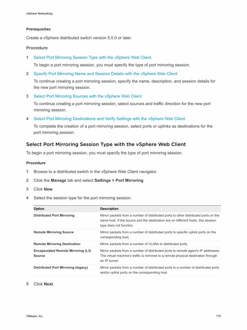
Prerequisites
Create a vSphere distributed switch version 5.0.0 or later.
Procedure
1 Select Port Mirroring Session Type with the vSphere Web Client
To begin a port mirroring session, you must specify the type of port mirroring session.
2 Specify Port Mirroring Name and Session Details with the vSphere Web Client
To continue creating a port mirroring session, specify the name, description, and session details forthe new port mirroring session.
3 Select Port Mirroring Sources with the vSphere Web Client
To continue creating a port mirroring session, select sources and traffic direction for the new portmirroring session.
4 Select Port Mirroring Destinations and Verify Settings with the vSphere Web Client
To complete the creation of a port mirroring session, select ports or uplinks as destinations for theport mirroring session.
Select Port Mirroring Session Type with the vSphere Web ClientTo begin a port mirroring session, you must specify the type of port mirroring session.
Procedure
1 Browse to a distributed switch in the vSphere Web Client navigator.
2 Click the Manage tab and select Settings > Port Mirroring
3 Click New.
4 Select the session type for the port mirroring session.
Option Description
Distributed Port Mirroring Mirror packets from a number of distributed ports to other distributed ports on thesame host. If the source and the destination are on different hosts, this sessiontype does not function.
Remote Mirroring Source Mirror packets from a number of distributed ports to specific uplink ports on thecorresponding host.
Remote Mirroring Destination Mirror packets from a number of VLANs to distributed ports.
Encapsulated Remote Mirroring (L3)Source
Mirror packets from a number of distributed ports to remote agent’s IP addresses.The virtual machine’s traffic is mirrored to a remote physical destination throughan IP tunnel.
Distributed Port Mirroring (legacy) Mirror packets from a number of distributed ports to a number of distributed portsand/or uplink ports on the corresponding host.
5 Click Next.
vSphere Networking
VMware, Inc. 175

Specify Port Mirroring Name and Session Details with thevSphere Web ClientTo continue creating a port mirroring session, specify the name, description, and session details for thenew port mirroring session.
Procedure
1 Set the session properties. Different options are available for configuration depending on whichsession type you selected.
Option Description
Name You can enter a unique name for the port mirroring session, or accept theautomatically generated session name.
Status Use the drop down menu to enable or disable the session.
Session type Displays the type of session you selected.
Normal I/O on destination ports Use the drop-down menu to allow or disallow normal I/O on destination ports.This property is only available for uplink and distributed port destinations.
If you disallow this option, mirrored traffic will be allowed out on destination ports,but no traffic will be allowed in.
Mirrored packet length (Bytes) Use the check box to enable mirrored packet length in bytes. This puts a limit onthe size of mirrored frames. If this option is selected, all mirrored frames aretruncated to the specified length.
Sampling rate Select the rate at which packets are sampled. This is enabled by default for allport mirroring sessions except legacy sessions.
Description You have the option to enter a description of the port mirroring sessionconfiguration.
2 Click Next.
Select Port Mirroring Sources with the vSphere Web ClientTo continue creating a port mirroring session, select sources and traffic direction for the new port mirroringsession.
You can create a port mirroring session without setting the source and destinations. When a source anddestination are not set, a port mirroring session is created without the mirroring path. This allows you tocreate a port mirroring session with the correct properties set. Once the properties are set, you can editthe port mirroring session to add the source and destination information.
vSphere Networking
VMware, Inc. 176

Procedure
1 Select the source of the traffic to be mirrored and the traffic direction.
Depending on the type of port mirroring session you selected, different options are available forconfiguration.
Option Description
Add existing ports from a list Click Select distributed ports. A dialog box displays a list of existing ports.Select the check box next to the distributed port and click OK. You can choosemore than one distributed port.
Add existing ports by port number Click Add distributed ports, enter the port number and click OK.
Set the traffic direction After adding ports, select the port in the list and click the ingress, egress, oringress/egress button. Your choice appears in the Traffic Direction column.
Specify the source VLAN If you selected a Remote Mirroring Destination sessions type, you must specifythe source VLAN. ClickAdd to add a VLAN ID. Edit the ID by using the up anddown arrows, or clicking in the field and entering the VLAN ID manually.
2 Click Next.
Select Port Mirroring Destinations and Verify Settings with thevSphere Web ClientTo complete the creation of a port mirroring session, select ports or uplinks as destinations for the portmirroring session.
You can create a port mirroring session without setting the source and destinations. When a source anddestination are not set, a port mirroring session is created without the mirroring path. This allows you tocreate a port mirroring session with the correct properties set. Once the properties are set, you can editthe port mirroring session to add the source and destination information.
Port mirroring is checked against the VLAN forwarding policy. If the VLAN of the original frames is notequal to or trunked by the destination port, the frames are not mirrored.
Procedure
1 Select the destination for the port mirroring session.
Depending on which type of session you chose, different options are available.
Option Description
Select a destination distributed port Click Select distributed ports to select ports from a list, or click Add distributedports to add ports by port number. You can add more than one distributed port.
Select an uplink Select an available uplink from the list and click Add to add the uplink to the portmirroring session. You can select more than one uplink.
vSphere Networking
VMware, Inc. 177

Option Description
Select ports or uplinks Click Select distributed ports to select ports from a list, or click Add distributedports to add ports by port number. You can add more than one distributed port.
Click Add uplinks to add uplinks as the destination. Select uplinks from the listand click OK.
Specify IP address Click Add. A new list entry is created. Select the entry and either click Edit toenter the IP address, or click directly in the IP Address field and type the IPaddress. A warning appears if the IP address is invalid.
2 Click Next.
3 Review the information that you entered for the port mirroring session on the Ready to completepage.
4 (Optional) Use the Back button to edit the information.
5 Click Finish.
The new port mirroring session appears in the Port Mirroring section of the Settings tab.
View Port Mirroring Session Details in the vSphere Web ClientView port mirroring session details, including status, sources, and destinations.
Procedure
1 Browse to a distributed switch in the vSphere Web Client navigator.
2 On the Manage tab click Settings > Port Mirroring.
3 Select a port mirroring session from the list to display more detailed information at the bottom of thescreen. Use the tabs to review configuration details.
4 (Optional) Click New to add a new port mirroring session.
5 (Optional) Click Edit to edit the details for the selected port mirroring session.
6 (Optional) Click Remove to delete the selected port mirroring session.
Edit Port Mirroring Session Details, Sources, and Destinations withthe vSphere Web ClientEdit the details of a port mirroring session, including name, description, status, sources, and destinations.
Procedure
1 Browse to a distributed switch in the vSphere Web Client navigator.
2 Click the Manage tab and select Settings > Port Mirroring.
3 Select a port mirroring session from the list and click Edit.
vSphere Networking
VMware, Inc. 178
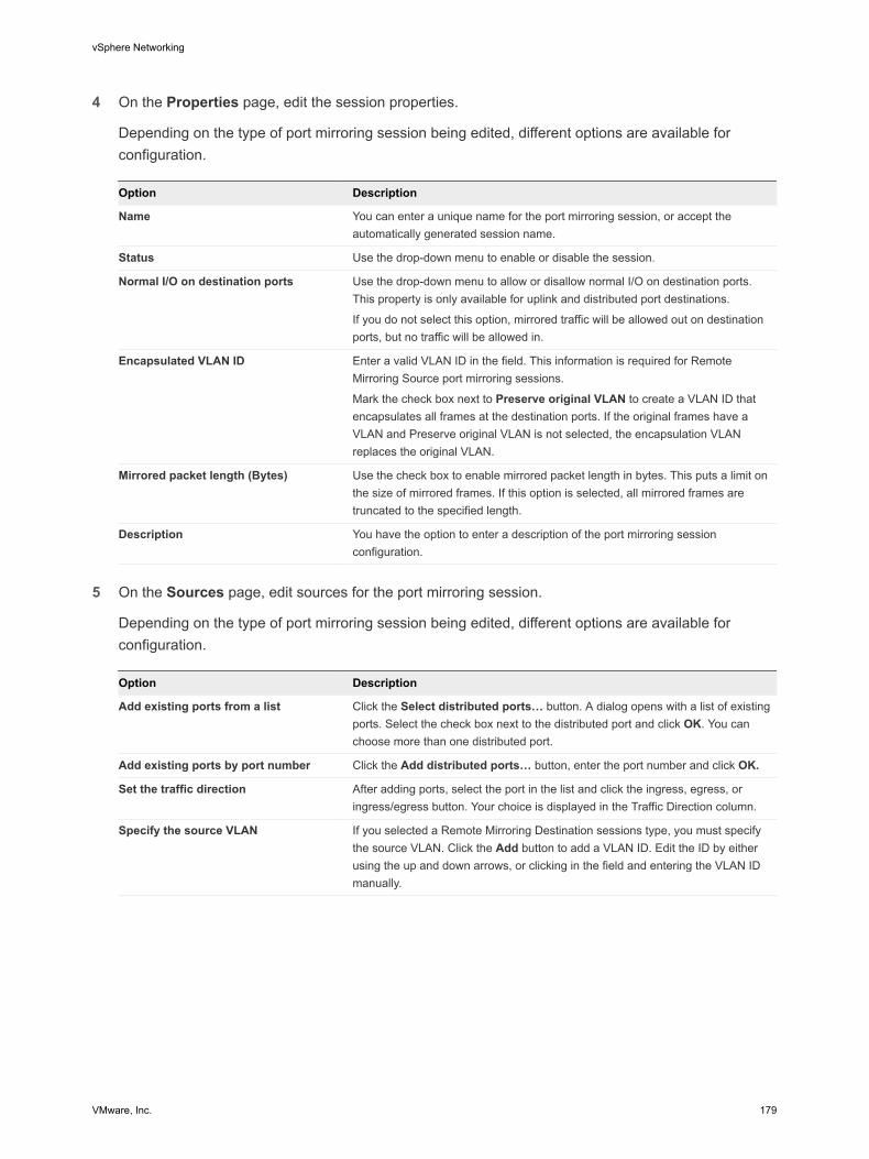
4 On the Properties page, edit the session properties.
Depending on the type of port mirroring session being edited, different options are available forconfiguration.
Option Description
Name You can enter a unique name for the port mirroring session, or accept theautomatically generated session name.
Status Use the drop-down menu to enable or disable the session.
Normal I/O on destination ports Use the drop-down menu to allow or disallow normal I/O on destination ports.This property is only available for uplink and distributed port destinations.
If you do not select this option, mirrored traffic will be allowed out on destinationports, but no traffic will be allowed in.
Encapsulated VLAN ID Enter a valid VLAN ID in the field. This information is required for RemoteMirroring Source port mirroring sessions.
Mark the check box next to Preserve original VLAN to create a VLAN ID thatencapsulates all frames at the destination ports. If the original frames have aVLAN and Preserve original VLAN is not selected, the encapsulation VLANreplaces the original VLAN.
Mirrored packet length (Bytes) Use the check box to enable mirrored packet length in bytes. This puts a limit onthe size of mirrored frames. If this option is selected, all mirrored frames aretruncated to the specified length.
Description You have the option to enter a description of the port mirroring sessionconfiguration.
5 On the Sources page, edit sources for the port mirroring session.
Depending on the type of port mirroring session being edited, different options are available forconfiguration.
Option Description
Add existing ports from a list Click the Select distributed ports… button. A dialog opens with a list of existingports. Select the check box next to the distributed port and click OK. You canchoose more than one distributed port.
Add existing ports by port number Click the Add distributed ports… button, enter the port number and click OK.
Set the traffic direction After adding ports, select the port in the list and click the ingress, egress, oringress/egress button. Your choice is displayed in the Traffic Direction column.
Specify the source VLAN If you selected a Remote Mirroring Destination sessions type, you must specifythe source VLAN. Click the Add button to add a VLAN ID. Edit the ID by eitherusing the up and down arrows, or clicking in the field and entering the VLAN IDmanually.
vSphere Networking
VMware, Inc. 179
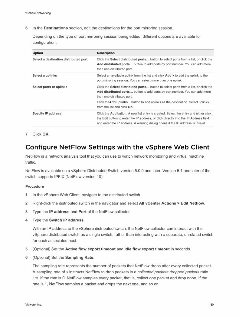
6 In the Destinations section, edit the destinations for the port mirroring session.
Depending on the type of port mirroring session being edited, different options are available forconfiguration.
Option Description
Select a destination distributed port Click the Select distributed ports… button to select ports from a list, or click theAdd distributed ports… button to add ports by port number. You can add morethan one distributed port.
Select a uplinks Select an available uplink from the list and click Add > to add the uplink to theport mirroring session. You can select more than one uplink.
Select ports or uplinks Click the Select distributed ports… button to select ports from a list, or click theAdd distributed ports… button to add ports by port number. You can add morethan one distributed port.
Click theAdd uplinks... button to add uplinks as the destination. Select uplinksfrom the list and click OK.
Specify IP address Click the Add button. A new list entry is created. Select the entry and either clickthe Edit button to enter the IP address, or click directly into the IP Address fieldand enter the IP address. A warning dialog opens if the IP address is invalid.
7 Click OK.
Configure NetFlow Settings with the vSphere Web ClientNetFlow is a network analysis tool that you can use to watch network monitoring and virtual machinetraffic.
NetFlow is available on a vSphere Distributed Switch version 5.0.0 and later. Version 5.1 and later of theswitch supports IPFIX (NetFlow version 10).
Procedure
1 In the vSphere Web Client, navigate to the distributed switch.
2 Right-click the distributed switch in the navigator and select All vCenter Actions > Edit Netflow.
3 Type the IP address and Port of the NetFlow collector.
4 Type the Switch IP address.
With an IP address to the vSphere distributed switch, the NetFlow collector can interact with thevSphere distributed switch as a single switch, rather than interacting with a separate, unrelated switchfor each associated host.
5 (Optional) Set the Active flow export timeout and Idle flow export timeout in seconds.
6 (Optional) Set the Sampling Rate.
The sampling rate represents the number of packets that NetFlow drops after every collected packet.A sampling rate of x instructs NetFlow to drop packets in a collected packets:dropped packets ratio1:x. If the rate is 0, NetFlow samples every packet, that is, collect one packet and drop none. If therate is 1, NetFlow samples a packet and drops the next one, and so on.
vSphere Networking
VMware, Inc. 180

7 (Optional) Enable or disable Process internal flows only with the drop-down menu.
When enabled, only data on network activity between virtual machines on the same host is collected.
8 Click OK.
Switch Discovery ProtocolSwitch discovery protocols help vSphere administrators to determine which port of the physical switch isconnected to a vSphere standard switch or vSphere distributed switch.
vSphere 5.0 and later supports Cisco Discovery Protocol (CDP) and Link Layer Discovery Protocol(LLDP). CDP is available for vSphere standard switches and vSphere distributed switches connected toCisco physical switches. LLDP is available for vSphere distributed switches version 5.0.0 and later.
When CDP or LLDP is enabled for a particular vSphere distributed switch or vSphere standard switch,you can view properties of the peer physical switch such as device ID, software version, and timeout fromthe vSphere Web Client.
Enable Cisco Discovery Protocol on a vSphere Distributed Switchwith the vSphere Web ClientCisco Discovery Protocol (CDP) allows vSphere administrators to determine which port of a physicalCisco switch connects to a vSphere standard switch or vSphere distributed switch. When CDP is enabledfor a vSphere distributed switch, you can view the properties of the Cisco switch such as device ID,software version, and timeout.
Procedure
1 Browse to a distributed switch in the vSphere Web Client navigator.
2 Click the Manage tab, and click Settings > Properties.
3 Click Edit.
4 Click Advanced.
5 In the Discovery Protocol section, select Cisco Discovery Protocol from the Type drop-downmenu .
6 Set the Operation from the drop-down menu.
Option Description
Listen ESXi detects and displays information about the associated Cisco switch port, butinformation about the vSphere distributed switch is not available to the Ciscoswitch administrator.
Advertise ESXi makes information about the vSphere distributed switch available to theCisco switch administrator, but does not detect and display information about theCisco switch.
Both ESXi detects and displays information about the associated Cisco switch andmakes information about the vSphere distributed switch available to the Ciscoswitch administrator.
vSphere Networking
VMware, Inc. 181

7 Click OK.
Enable Link Layer Discovery Protocol on a vSphere DistributedSwitch in the vSphere Web ClientWith Link Layer Discovery Protocol (LLDP), vSphere administrators can determine which physical switchport connects to a given vSphere distributed switch. When LLDP is enabled for a particular distributedswitch, you can view properties of the physical switch (such as chassis ID, system name and description,and device capabilities) from the vSphere Web Client.
LLDP is available only on vSphere distributed switch version 5.0.0 and later.
Procedure
1 Browse to a distributed switch in the vSphere Web Client navigator.
2 Click the Manage tab, and select Settings > Properties.
3 Click Edit.
4 Click Advanced.
5 Select Link Layer Discovery Protocol from the Type drop-down menu.
6 Set Operation to Listen, Advertise, or Both.
Operation Description
Listen ESXi detects and displays information about the associated physical switch port,but information about the vSphere distributed switch is not available to the switchadministrator.
Advertise ESXi makes information about the vSphere distributed switch available to theswitch administrator, but does not detect and display information about thephysical switch.
Both ESXi detects and displays information about the associated physical switch andmakes information about the vSphere distributed switch available to the switchadministrator.
7 Click OK.
View Switch Information with the vSphere Web ClientWhen CDP or LLDP is set to Listen or Both, you can view physical switch information from thevSphere Web Client.
Procedure
1 Browse to a host in the vSphere Web Client navigator.
2 Click the Manage tab, and click Networking > Physical adapters.
3 Select a physical adapter from the list to view detailed information.
vSphere Networking
VMware, Inc. 182

Depending on the enabled switch discovery protocol, the properties of the switch appear under CiscoDiscovery Protocol or Link Layer Discovery Protocol. If the information is available in the network, underPeer device capability you can see the system capabilities of the switch.
Mounting NFS VolumesESXi supports VMkernel-based NFS mounts for storing virtual disks on NFS datastores.
In addition to storing virtual disks on NFS datastores, you can also use NFS Datastores as a centralrepository for ISO images and virtual machine templates. For more information about creating NFSdatastores, see the vSphere Storage documentation.
ESXi supports NFS version 3 over Layer 2 and Layer 3 Network switches.
Networking Rollback and RecoveryIn vSphere 5.1 and later, you can prevent and recover from network misconfiguration by using rollback,backup configuration files or previous configurations.
vSphere 5.1 and later can rollback to previous valid networking configuration if a misconfiguration of themanagement network occurs. To recover from misconfiguration, you can connect directly to a host to fixany networking issues through the DCUI. Rollback is available for use on both standard and distributedswitches.
vSphere Networking RollbackBy rolling configuration changes back, vSphere protects hosts from losing connection to vCenter Serveras a result from misconfiguration of the management network.
In vSphere 5.1 and later, networking rollback is enabled by default. However, you can enable or disablerollbacks at the vCenter Server level.
Host Networking RollbacksHost networking rollbacks occur when an invalid change is made to the networking configuration for theconnection with vCenter Server. Every network change that disconnects a host also triggers a rollback.The following examples of changes to the host networking configuration might trigger a rollback:
n Updating the speed or duplex of a physical NIC.
n Updating DNS and routing settings.
n Updating teaming and failover policies or traffic shaping policies of a standard port group thatcontains the management VMkernel network adapter.
n Updating the VLAN of a standard port group that contains the management VMkernel networkadapter.
n Increasing the MTU of management VMkernel network adapter and its switch to values not supportedby the physical infrastructure.
n Changing the IP settings of management VMkernel network adapters.
vSphere Networking
VMware, Inc. 183

n Removing the management VMkernel network adapter from a standard or distributed switch.
n Removing a physical NIC of a standard or distributed switch containing the management VMkernelnetwork adapter.
If a network disconnects for any of these reasons, the task fails and the host reverts to the last validconfiguration.
vSphere Distributed Switch RollbacksDistributed switch rollbacks occur when invalid updates are made to distributed switches, distributed portgroups, or distributed ports. The following changes to the distributed switch configuration trigger arollback:
n Changing the MTU of a distributed switch.
n Changing the following settings in the distributed port group of the management VMkernel networkadapter:
n Teaming and failover
n VLAN
n Traffic shaping
n Blocking all ports in the distributed port group containing the management VMkernel network adapter.
n Overriding the policies on at the level of the distributed port for the management VMkernel networkadapter.
If a configuration becomes invalid because of any of the changes, one or more hosts might become out ofsynchronization with the distributed switch.
If you know where the conflicting configuration setting is located, you can manually correct the setting.For example, if you have migrated a management VMkernel network adapter to a new VLAN, the VLANmight not be actually trunked on the physical switch. When you correct the physical switch configuration,the next distributed switch-to-host synchronization will resolve the configuration problem.
If you are not sure where the problem exists, you can restore the state of the distributed switch ordistributed port group to an earlier configuration. See Restore a vSphere Distributed Port GroupConfiguration with the vSphere Web Client.
Disable Network Rollback with the vSphere Web ClientRollback is enabled by default in vSphere 5.1 and later. You can disable rollback in vCenter Server usingthe vSphere Web Client.
Procedure
1 Browse to a vCenter Server instance in the vSphere Web Client navigator.
2 Click the Manage tab, and select Settings..
3 Select Advanced Settings and click Edit.
vSphere Networking
VMware, Inc. 184

4 Select the config.vpxd.network.rollback key, and change the value to false.
If the key is not present, you can add it and set the value to false.
5 Click OK.
6 Restart vCenter Server to apply the changes.
Disable Network Rollback by Using the vCenter Server Configuration FileRollback is enabled by default in vSphere 5.1 and later. You can disable rollback by editing the vpxd.cfgconfiguration file of vCenter Server directly.
Procedure
1 On the host machine of vCenter Server, navigate to the directory that contains the configuration file:
n On a Windows Server operating system, the location of the directory is vCenter Server homedirectory\Application Data\VMware\VMware VirtualCenter.
n On the vCenter Server Appliance, the location of the directory is /etc/vmware-vpx.
2 Open the vpxd.cfg file for editing.
3 In the <network> element, set the <rollback> element to false:
<config>
<vpxd>
<network>
<rollback>false</rollback>
</network>
</vpxd>
</config>
4 Save and close the file.
5 Restart the vCenter Server system.
Restore a Previous Networking Configuration with thevSphere Web ClientYou can restore a previous configuration of a vSphere distributed switch or port group to revoke invalidchanges.
Procedure
1 In the vSphere Web Client, navigate to the affected a vSphere distributed switch, or to a distributed oruplink port group.
2 Right-click the affected switch or port group and select All vCenter Actions > RestoreConfiguration.
vSphere Networking
VMware, Inc. 185

3 If you are restoring the configuration of a distributed switch, provide a backup file.
a Click Browse and navigate to the location of the distributed switch backup file.
b Select Restore distributed switch and all port groups or Restore distributed switch only.
c Click Next.
4 If you are restoring the configuration of a distributed port group or uplink port group:
a Select Restore to previous configuration or Restore configuration from a file.
Restore to previous configuration reverts the configuration one step back.
b If restoring from a file, click Browse to navigate to the location of a port group backup file.
c Click Next.
5 Review the configuration information and click Finish.
Resolve Errors in the Management Network Configuration on avSphere Distributed SwitchIn vSphere 5.1 and later, you can use the Direct Console User Interface (DCUI) to restore the connectionbetween vCenter Server and a host that accesses the management network through a distributed switch.
If networking rollback is disabled, misconfiguring the port group for the management network on thedistributed switch leads to loss of connection between vCenter Server and the hosts added to the switch.You have to use the DCUI to connect each host individually.
For more information about accessing and using the DCUI, see the vSphere Security documentation.
Note Recovery of the management connection on a distributed switch is not supported on statelessESXi instances.
Prerequisites
Verify that the management network is configured on a port group on the distributed switch.
Procedure
1 Connect to the DCUI of the host.
2 From the Network Restore Options menu, select Restore vDS.
3 Configure the uplinks and optionally the VLAN for the management network.
4 Apply the configuration.
The DCUI creates a local ephemeral port and applies the values you provided for the VLAN and uplinks.The DCUI moves the VMkernel adapter for the management network to the new local port to restoreconnectivity to vCenter Server.
vSphere Networking
VMware, Inc. 186

What to do next
After the connection of the host to vCenter Server is restored, correct the configuration of the distributedport group and re-add the VMkernel adapter to the group.
Configuring Protocol Profiles for Virtual MachineNetworkingA network protocol profile contains a pool of IPv4 and IPv6 addresses that vCenter Server assigns tovApps or to virtual machines with vApp functionality that are connected to port groups associated with theprofile.
Network protocol profiles also contain settings for the IP subnet, DNS, and HTTP proxy server.
To configure the networking settings of virtual machines by using from network protocol profiles, performthe following operations:
n Create network profiles at the level of a datacenter or a vSphere distributed switch.
n Associate a protocol profile with the port group of a vApp virtual machine.
n Enable the transient or static IP allocation policy from the settings of the vApp or from the vAppoptions of a virtual machine.
Note If you move a vApp or a virtual machine that retrieves its network settings from a protocol profile toanother datacenter, to power it on you must assign a protocol profile to the connected port group on thedestination datacenter.
n Add a Network Protocol Profile
A network protocol profile contains a pool of IPv4 and IPv6 addresses. vCenter Server assigns thoseresources to vApps or to virtual machines with vApp functionality that are connected to port groupsassociated with the profile.
n Associate a Port Group with a Network Protocol Profile in the vSphere Web Client
To apply the range of IP addresses from a network protocol profile to a virtual machine that is a partof a vApp or has vApp functionality enabled, associate the profile with a port group that controls thenetworking of the virtual machine.
n Configure a Virtual Machine or vApp to Use a Network Protocol Profile in the vSphere Web Client
After you associate a protocol profile to a port group of a standard switch or a distributed switch,enable the usage of profile on a virtual machine that is connected to the port group and is associatedwith a vApp or has the vApp options enabled.
Add a Network Protocol ProfileA network protocol profile contains a pool of IPv4 and IPv6 addresses. vCenter Server assigns thoseresources to vApps or to virtual machines with vApp functionality that are connected to port groupsassociated with the profile.
vSphere Networking
VMware, Inc. 187

Network protocol profiles also contain settings for the IP subnet, DNS, and HTTP proxy server.
Note If you move a vApp or a virtual machine that retrieves its network settings from a protocol profile toanother datacenter, to power on the vApp or virtual machine you must assign a protocol profile to theconnected port group on the destination datacenter.
Procedure
1 Navigate to a datacenter that is associated with the vApp and click the Manage tab.
2 Click Network Protocol Profiles
Existing network protocol profiles are listed.
3 Click the Add icon ( ) to add a new network protocol profile.
Select the Network Protocol Profile Name and NetworkName the network protocol profile and select the network that should use it.
Procedure
1 Type the name of the network protocol profile.
2 Select the networks that use this network protocol profile.
A network can be associated with one network protocol profile at a time.
3 Click Next.
Specify Network Protocol Profile IPv4 ConfigurationA network protocol profile contains a pool of IPv4 and IPv6 addresses for use by vApps. When you createa network protocol profile, you set up its IPv4 configuration.
You can configure network protocol profile ranges for IPv4, IPv6, or both. vCenter Server uses theseranges to dynamically allocate IP addresses to virtual machines when a vApp is set up to use transient IPallocation.
Procedure
1 Enter the IP Subnet and Gateway in their respective fields.
2 Select DHCP Present to indicate that the DHCP server is available on this network.
3 Enter the DNS server information.
Specify the servers by IP addresses separated by a comma, semicolon, or space.
4 Select the Enable IP Pool check box to specify an IP pool range.
vSphere Networking
VMware, Inc. 188

5 If you enable IP Pools, enter a comma-separated list of host address ranges in the IP pool rangefield.
A range consists of an IP address, a pound sign (#), and a number indicating the length of the range.
The gateway and the ranges must be within the subnet. The ranges that you enter in the IP poolrange field cannot include the gateway address.
For example, 10.20.60.4#10, 10.20.61.0#2 indicates that the IPv4 addresses can range from10.20.60.4 to 10.20.60.13 and 10.20.61.0 to 10.20.61.1.
6 Click Next.
Specify Network Protocol Profile IPv6 ConfigurationA network protocol profile contains a pool of IPv4 and IPv6 addresses for use by vApps. When you createa network protocol profile, you set up its IPv6 configuration.
You can configure network protocol profile ranges for IPv4, IPv6, or both.vCenter Server uses theseranges to dynamically allocate IP addresses to virtual machines when a vApp is set up to use transient IPallocation.
Procedure
1 Enter the IP Subnet and Gateway in their respective fields.
2 Select DHCP Present to indicate that the DHCP server is available on this network.
3 Enter the DNS server information.
Specify the servers by IP addresses separated by a comma, semicolon, or space.
4 Select the Enable IP Pool check box to specify an IP pool range.
5 If you enable IP Pools, enter a comma-separated list of host address ranges in the IP pool rangefield.
A range consists of an IP address, a pound sign (#), and a number indicating the length of the range.For example. assume that you specify the following IP pool range:
fe80:0:0:0:2bff:fe59:5a:2b#10,fe80:0:0:0:2bff:fe59:5f:b1#2
Then the addresses are in this range:
fe80:0:0:0:2bff:fe59:5a:2b - fe80:0:0:0:2bff:fe59:5a:34
and
fe80:0:0:0:2bff:fe59:5f:b1 - fe80:0:0:0:2bff:fe59:5f:b2
The gateway and the ranges must be within the subnet. The ranges that you enter in the IP poolrange field cannot include the gateway address.
6 Click Next.
vSphere Networking
VMware, Inc. 189

Specify Network Protocol Profile DNS and Other ConfigurationWhen you create a network protocol profile, you can specify the DNS domain, DNS search path, a hostprefix, and HTTP proxy.
Procedure
1 Enter the DNS domain.
2 Enter the host prefix.
3 Enter the DNS search path.
The search paths are specified as a list of DNS domains separated by commas, semi-colons, orspaces.
4 Enter the server name and port number for the proxy server.
The server name can optionally include a colon and a port number.
For example, web-proxy:3912 is a valid proxy server.
5 Click Next.
Complete the Network Protocol Profile Creation
Procedure
u Review the settings and click Finish to complete adding the network protocol profile.
Associate a Port Group with a Network Protocol Profile in thevSphere Web ClientTo apply the range of IP addresses from a network protocol profile to a virtual machine that is a part of avApp or has vApp functionality enabled, associate the profile with a port group that controls thenetworking of the virtual machine.
You can associate a port group of a standard switch or a distributed port group of a distributed switch witha network protocol profile by using the settings of the group.
Procedure
1 Navigate to a distributed port group of a vSphere distributed switch or to a port group of a vSpherestandard switch in the Networking view of the vSphere Web Client.
The port groups of standard switches are under the datacenter. The vSphere Web Client displaysdistributed port groups under the parent distributed switch object.
2 On the Manage tab, click Network Protocol Profiles.
3 Click Associate a network protocol profile with the selected network.
vSphere Networking
VMware, Inc. 190

4 On the Set association type page of the Associate Network Protocol Profile wizard, select Use anexisting network protocol profile and click Next.
If the existing network protocol profiles do not contain settings suitable for the vApp virtual machinesin the port group, you must create a new profile.
5 Select the network protocol profile and click Next.
6 Examine the association and settings of the network protocol profile and click Finish.
Configure a Virtual Machine or vApp to Use a Network ProtocolProfile in the vSphere Web ClientAfter you associate a protocol profile to a port group of a standard switch or a distributed switch, enablethe usage of profile on a virtual machine that is connected to the port group and is associated with a vAppor has the vApp options enabled.
Prerequisites
Verify that the virtual machine is connected to a port group that is associated with the network protocolprofile.
Procedure
1 Navigate to the virtual machine or the vApp in the inventory of the vSphere Web Client.
2 In the vSphere Web Client, open the settings of the vApp or the vApp Options tab of the virtualmachine.
n Right-click a vApp and select Edit settings.
n Right-click a virtual machine, select Edit settings, and in the Edit Settings dialog box, click thevApp Options tab.
3 Click Enable vApp options.
4 Under Authoring, expand IP allocation and set the IP allocation scheme to OVF environment.
5 Under Deployment, expand IP allocation and set IP allocation to Transient - IP Pool or Static - IPPool.
Both the Static - IP Pool and Transient - IP Pool options allocate an IP address from the range inthe network protocol profile that is associated with the port group. If you select Static - IP Pool, the IPaddress is assigned the first time the virtual machine or vApp is powered on and the address persistsacross restarts. If you select Transient - IP Pool, an IP address is assigned every time the virtualmachine or vApp is powered on.
6 Click OK.
When the virtual machine is powered on, the adapters connected to the port group receive IP addressesfrom the range in the protocol profile. When the virtual machine is powered off, the IP addresses arereleased.
vSphere Networking
VMware, Inc. 191

Stateless Network DeploymentStateless is a mode of execution for ESXi hosts with no local storage that formerly would saveconfiguration or state. Configurations are abstracted into a host profile, which is a template that applies toa class of machines. Stateless allows easy replacement, removal, and addition of failed hardware, andimproves the ease of scaling a hardware deployment.
Every stateless ESXi boot is like a first boot. The ESXi host boots with networking connectivity tovCenter Server through the built‐in standard switch. If the host profile specifies distributed switchmembership, vCenter Server joins the ESXi host to VMware distributed switches or a third party switchsolution.
When planning the network setup for stateless ESXi hosts, you should keep the configuration as genericas possible and avoid host‐specific items. Currently the design has no hooks to reconfigure physicalswitches when deploying a new host. Any such requirement would need special handling.
To set up stateless deployment, one ESXi host must be installed in the standard fashion. Then find andrecord the following network-related information to save in the host profile:
n vSphere standard switch instances and settings (port groups, uplinks, MTU, and so forth)
n Distributed switch instances (VMware and third party)
n Selection rules for uplinks and uplink port or port groups
n vNIC information:
n Address information (IPv4 or IPv6, static or DHCP, gateway)
n Port groups and distributed port groups assigned to the physical network adapter (vmknic)
n If there are distributed switches, record VLAN, physical NICs bound to the vmknic, and ifEtherchannel is configured
The recorded information is used as a template for the host profile. Once the host profile virtual switchinformation has been extracted and placed in the host profile, you have the opportunity to change any ofthe information. Modifications are offered for both standard and distributed switches in these sections:uplink selection policy, based on either vmnic name or device number, and auto discovery based onVLAN ID. The (possibly modified) information is stored by the stateless boot infrastructure and applied toa stateless ESXi host on its next boot. During network initialization, a generic network plug‐in interpretsthe recorded host profile setting and does the following:
n Loads appropriate physical NIC drivers.
n Creates all standard switch instances, along with port groups. It selects uplinks based on policy. If thepolicy is based on the VLAN ID, there is a probing process to gather relevant information.
n For VMkernel network adapters connected to the standard switch, it creates VMkernel networkadapters and connects them to port groups.
vSphere Networking
VMware, Inc. 192

n For each VMkernel network adapter connected to a distributed switch, it creates a temporarystandard switch (as needed) with uplinks bound to the VMkernel network adapter. It creates atemporary port group with VLAN and teaming policies based on recorded information. Specifically, IP‐hash is used if Etherchannel was used in the distributed switch.
n Configures all VMkernel network adapter settings (assigns address, gateway, MTU, and so forth).
Basic connectivity is functioning, and the networking setup is complete if there is no distributed switchpresent.
If there is a distributed switch present, the system stays in maintenance mode until distributed switchremediation is complete. No virtual machines are started at this time. Because distributed switchesrequires vCenter Server, the boot process continues until vCenter Server connectivity is established, andvCenter Server notices that the host should be part of a distributed switch. It issues a distributed switchhost join, creating a distributed switch proxy standard switch on the host, selects appropriate uplinks, andmigrates the vmknic from the standard switch to the distributed switch. When this operation is complete, itdeletes the temporary standard switch and port groups.
At the end of the remediation process, the ESXi host is taken out of maintenance mode, and HA or DRScan start virtual machines on the host.
In the absence of a host profile, a temporary standard switch is created with “default networking” logic,which creates a management network switch (with no VLAN tag) whose uplink corresponds to the PXEbooting vNIC. A vmknic is created on the management network port group with the same MAC addressas the PXE booting vNIC. This logic was previously used for PXE booting. If there is a host profile, but thenetworking host profile is disabled or fatally incomplete, vCenter Server falls back to default networking sothat the ESXi host can be managed remotely. This triggers a compliance failure, so vCenter Server theninitiates recovery actions.
vSphere Networking
VMware, Inc. 193

Monitoring Network Packets 9Monitor network packets that pass through the ports of a vSphere Standard Switch or a vSphereDistributed Switch to analyze the traffic between virtual machines and hosts.
Capturing and Tracing Network Packets by Using thepktcap-uw UtilityMonitor the traffic that flows through physical network adapters, VMkernel adapters, and virtual machinesadapters, and analyze packet information by using the graphical user interface of network analysis toolssuch as Wireshark.
In vSphere 5.5 or later, you can monitor packets on a host by using the pktcap-uw console utility. Youcan use the utility without additional installation on an ESXi host. pktcap-uw provides many points in thehost network stack at which you can monitor traffic.
For detailed analysis of captured packets, you can save packet content from the pktcap-uw utility to filesin PCAP or PCAPNG format and open them in Wireshark. You can also troubleshoot dropped packetsand trace a packet's path in the network stack.
Note The pktcap-uw utility is not fully supported for backward compatibility across vSphere releases.The options of the utility might change in the future.
pktcap-uw Command Syntax for Capturing PacketsUse the pktcap-uw utility to inspect the contents of packets while they traverse the network stack on anESXi host.
pktcap-uw Syntax for Capturing PacketsThe pktcap-uw command has the following syntax for capturing packets at a certain place in the networkstack:
pktcap-uw switch_port_arguments capture_point_options filter_options output_control_options
Note Certain options of the pktcap-uw utility are designed for VMware internal use only and you shoulduse them only under the supervision of VMware Technical Support. These options are not described inthe vSphere Networking guide.
VMware, Inc. 194

Table 9‑1. pktcap-uw Arguments for Capturing Packets
Argument Group Argument Description
switch_port_arguments --uplink vmnicX Capture packets that are related toa physical adapter.
You can combine the --uplink and--capture options for monitoringpackets at a certain place in thepath between the physical adapterand the virtual switch.
See Capture Packets That Arrive ata Physical Adapter.
--vmk vmkX Capture packets that are related toa VMKernel adapter.
You can combine the vmk and--capture options for monitoringpackets at a certain place in thepath between the VMkernel adapterand the virtual switch.
See Capture Packets for aVMkernel Adapter.
--switchport {vmxnet3_port_ID |
vmkernel_adapter_port_ID}
Capture packets that are related toa VMXNET3 virtual machineadapter or to a VMkernel adapterthat is connected to a particularvirtual switch port. You can view theID of the port in the network panelof the esxtop utility.
You can combine the switchportand capture options for monitoringpackets at a certain place in thepath between the VMXNET3adapter or VMkernel adapter andthe virtual switch.
See Capture Packets for aVMXNET3 Virtual Machine Adapter.
--lifID lif_ID Capture packets that are related tothe logical interface of a distributedrouter. See the VMware NSXdocumentation.
capture_point_options --capture capture_point Capture packets at a particularplace in the network stack. Forexample, you can monitor packetsright after they arrive from aphysical adapter.
vSphere Networking
VMware, Inc. 195

Table 9‑1. pktcap-uw Arguments for Capturing Packets (Continued)
Argument Group Argument Description
--dir {0|1} Capture packets according to thedirection of the flow with regard tothe virtual switch.
0 stands for incoming traffic and 1for outgoing traffic.
By default, the pktcap-uw utilitycaptures ingress traffic.
Use the --dir option together withthe --uplink, --vmk, or--switchport option.
--stage {0|1} Capture the packet closer to itssource or to its destination. Use thisoption to examine how a packagechanges while it traverses thepoints in the stack.
0 stands for traffic closer to sourceand 1 for traffic closer todestination.
Use the --stage option togetherwith the --uplink, --vmk ,--switchport, or --dvfilteroption.
--dvfilter filter_name --capture
PreDVFilter|PostDVFilter
Capture packets before or after avSphere Network Appliance(DVFilter) intercepts them. See Capture Packets at DVFilter Level.
-A | --availpoints View all capture points that thepktcap-uw utility supports.
For details about the capture points of the pktcap-uw utility, see Capture Points of thepktcap-uw Utility.
filter_options Filter captured packets according to source or destination address, VLAN ID, VXLAN ID,Layer 3 protocol, and TCP port. See pktcap-uw Options for Filtering Packets.
output_control_options Save the contents of a packet to a file, capture only a number of packets, and capture anumber of bytes at the beginning of packets, and so on. See pktcap-uw Options for OutputControl.
The vertical bars | represent alternative values, and the curly brackets {} used with vertical bars specify alist of choices for an argument or option.
pktcap-uw Command Syntax for Tracing PacketsUse the pktcap-uw utility to view the path of a packet in the network stack on an ESXi host for latencyanalysis.
vSphere Networking
VMware, Inc. 196

pktcap-uw Syntax for Tracing PacketsThe command of the pktcap-uw utility has the following syntax for tracing packets in the network stack:
pktcap-uw --trace filter_options output_control_options
Options to the pktcap-uw Utility for Tracing PacketsThe pktcap-uw utility supports the following options when you use it to trace packets:
Table 9‑2. pktcap-uw Options for Tracing Packets
Argument Description
filter_options Filter traced packets according to source or destination address,VLAN ID, VXLAN ID, Layer 3 protocol, and TCP port. See pktcap-uw Options for Filtering Packets.
output_control_options Save the contents of a packet to a file and trace only a numberof packets. See pktcap-uw Options for Output Control.
pktcap-uw Options for Output ControlUse the options for output control of the pktcap-uw utility to save packet contents to a file, capture up toa certain number of bytes from each packet, and limit the number of captured packets.
pktcap-uw Options for Output ControlThe options of the pktcap-uw utility for output control are valid when you capture and trace packets. Forinformation about the command syntax of the pktcap-uw utility, see pktcap-uw Command Syntax forCapturing Packets and pktcap-uw Command Syntax for Tracing Packets.
Table 9‑3. Options for Output Control That Are Supported by the pktcap-uw Utility
Option Description
{-o | --outfile} pcap_file Save captured or traced packets to a file in packet capture(PCAP) format. Use this option to examine packets in a visualanalyzer tool such as Wireshark.
-P | --ng Save packet content in the PCAPNG file format. Use this optiontogether with the -o or --outfile option.
--console Print packet details and content to the console output. Bydefault, the pktcap-uw utility shows packet information in theconsole output.
{-c | --count} number_of_packets Capture the first number_of_packets packets.
vSphere Networking
VMware, Inc. 197

Table 9‑3. Options for Output Control That Are Supported by the pktcap-uw Utility(Continued)
Option Description
{-s | --snaplen} snapshot_length Capture only the first snapshot_length bytes from each packet. Iftraffic on the host is intensive, use this option to reduce the loadon the CPU and storage.
To limit the size of captured contents, set a value greater than24.
To capture the complete packet, set this option to 0.
-h View help about the pktcap-uw utility.
The vertical bars | represent alternative values, and the curly brackets {} used with vertical bars specify alist of choices for an argument or option.
pktcap-uw Options for Filtering PacketsNarrow the range of packets that you monitor by using the pktcap-uw utility to apply filtering options forsource and destination address, VLAN, VXLAN, and next level protocol consuming the packet payload.
Filter OptionsThe filter options for pktcap-uw are valid when you capture and trace packets. For information about thecommand syntax of the pktcap-uw utility, see pktcap-uw Command Syntax for Capturing Packets and pktcap-uw Command Syntax for Tracing Packets.
Table 9‑4. Filter Options of the pktcap-uw Utility
Option Description
--srcmac mac_address Capture or trace packets that have a specific source MACaddress. Use colons to separate the octets in it.
--dstmac mac_address Capture or trace packets that have a specific destination MACaddress. Use colons to separate the octets in it.
--mac mac_address Capture or trace packets that have a specific source ordestination MAC address. Use colons to separate the octets init.
--ethtype 0xEthertype Capture or trace packets at Layer 2 according to the next levelprotocol that consumes packet payload.
EtherType corresponds to the EtherType field in Ethernetframes . It represents the type of next level protocol thatconsumes the payload of the frame.
For example, to monitor traffic for the Link Layer DiscoveryProtocol (LLDP) protocol, type --ethtype 0x88CC.
--vlan VLAN_ID Capture or trace packets that belong to a VLAN.
--srcip IP_addess|IP_address/subnet_range Capture or trace packets that have a specific source IPv4address or subnet.
--dstip IP_addess|IP_address/subnet_range Capture or trace packets that have a specific destination IPv4address or subnet.
vSphere Networking
VMware, Inc. 198

Table 9‑4. Filter Options of the pktcap-uw Utility (Continued)
Option Description
--ip IP_addess Capture or trace packets that have a specific source ordestination IPv4 address.
--proto 0xIP_protocol_number Capture or trace packets at Layer 3 according to the next levelprotocol that consumes the payload.
For example, to monitor traffic for the UDP protocol, type--proto 0x11.
--srcport source_port Capture or trace packets according to their source TCP port.
--dstport destination_port Capture or trace packets according to their destination TCP port.
--tcpport TCP_port Capture or trace packets according to their source or destinationTCP port.
--vxlan VXLAN_ID Capture or trace packets that belong to a VXLAN.
The vertical bars | represent alternative values.
Capturing Packets by Using the pktcap-uw UtilityCapture packets through the pktcap-uw utility in the path between a virtual switch and the physicaladapters, VMkernel adapters and virtual machine adapters to troubleshoot data transfer in the networkstack on an ESXi host.
Capture Packets That Arrive at a Physical AdapterMonitor host traffic related to the external network by capturing packets at certain points in the pathbetween a vSphere Standard Switch or vSphere Distributed Switch and a physical adapter.
You can specify a certain capture point in the data path between a virtual switch and a physical adapter,or determine a capture point by traffic direction with regard to the switch and proximity to the packetsource or destination. For information about supported capture points, see Capture Points of the pktcap-uw Utility.
Procedure
1 (Optional) Find the name of the physical adapter that you want to monitor in the host adapter list.
n In the vSphere Web Client, on the Manage tab for the host, click Networking and selectPhysical adapters.
n In the ESXi Shell to the host, to view a list of the physical adapters and examine their state, runthe following ESXCLI command:
esxcli network nic list
Each physical adapter is represented as vmnicX. X is the number that ESXi assigned to the physicaladapter port.
vSphere Networking
VMware, Inc. 199

2 In the ESXi Shell to the host, run the pktcap-uw command with the --uplink vmnicX argument andwith options to monitor packets at a particular point, filter captured packets and save the result to afile.
pktcap-uw --uplink vmnicX [--capture capture_point|--dir 0|1] [filter_options] [--outfile
pcap_file_path [--ng]] [--count number_of_packets]
where the square brackets [] enclose the options of the pktcap-uw --uplink vmnicX commandand the vertical bars | represent alternative values.
If you run the pktcap-uw --uplink vmnicX command without options, you obtain the content ofpackets that are incoming to the standard or distributed switch in the console output at the pointwhere they are switched.
a Use the --capture option to check packets at another capture point or the --dir option atanother traffic direction.
pktcap-uw Command Option Goal
--capture UplinkSnd Monitor packets immediately before they enter the physical adapter device.
--capture UplinkRcv Monitor packets immediately after they are received in the network stack fromthe physical adapter.
--dir 1 Monitor packets that leave the virtual switch.
--dir 0 Monitor packets that enter the virtual switch.
b Use a filter_options to filter packets according to source and destination address, VLAN ID,VXLAN ID, Layer 3 protocol, and TCP port.
For example, to monitor packets from a source system that has IP address 192.168.25.113, usethe --srcip 192.168.25.113 filter option.
c Use options to save the contents of each packet or the contents of a limited number of packets toa .pcap or .pcapng file.
n To save packets to a .pcap file, use the --outfile option.
n To save packets to a .pcapng file, use the --ng and --outfile options.
You can open the file in a network analyzer tool such as Wireshark.
By default, the pktcap-uw tool saves the packet files to the root folder of the ESXi file system.
d Use the--count option to monitor only a number of packets.
3 If you have not limited the number of packets by using the --count option, press Ctrl+C to stopcapturing or tracing packets.
vSphere Networking
VMware, Inc. 200

Example: Capture Packets That Are Received at vmnic0 from an IP Address 192.168.25.113
To capture the first 60 packets from a source system that is assigned the IP address 192.168.25.113 atvmnic0 and save them to a file called vmnic0_rcv_srcip.pcap, run the following pktcap-uw command:
pktcap-uw --uplink vmnic0 --capture UplinkRcv --srcip 192.168.25.113 --outfile vmnic0_rcv_srcip.pcap
--count 60
What to do next
If the contents of the packet are saved to a file, copy the file from the ESXi host to the system that runs agraphical analyzer tool, such as Wireshark, and open it in the tool to examine the packet details.
Capture Packets for a VMXNET3 Virtual Machine AdapterMonitor traffic that flows between a virtual switch and a VMXNET3 virtual machine adapter by using thepktcap-uw utility.
You can specify a certain capture point in the data path between a virtual switch and a virtual machineadapter. You can also determine a capture point by traffic direction with regard to the switch and proximityto the packet source or destination. For information about supported capture points, see Capture Pointsof the pktcap-uw Utility.
Prerequisites
Verify that the virtual machine adapter is of type VMXNET3.
Procedure
1 On the host, learn the port ID of the virtual machine adapter by using the esxtop utility.
a In the ESXi Shell to the host, to start the utility, run esxtop.
b Press N to switch to the network panel of the utility.
c In the USED-BY column, locate the virtual machine adapter, and write down the PORT-ID valuefor it.
The USED-BY field contains the name of the virtual machine and the port to which the virtualmachine adapter is connected.
d Press Q to exit esxtop.
2 In the ESXi Shell to the host, run pktcap-uw --switchport port_ID.
port_ID is the ID that the esxtop utility displays for the virtual machine adapter in the PORT-IDcolumn.
vSphere Networking
VMware, Inc. 201

3 In the ESXi Shell to the host, run the pktcap-uw command with the --switchport port_IDargument and with options to monitor packets at a particular point, filter captured packets and savethe result to a file.
pktcap-uw --switchport port_ID [--capture capture_point|--dir 0|1 --stage 0|1] [filter_options]
[--outfile pcap_file_path [--ng]] [--count number_of_packets]
where the square brackets [] enclose the options of the pktcap-uw --switchport port_IDcommand and the vertical bars | represent alternative values.
If you run the pktcap-uw --switchport port_ID command without options, you obtain the contentof packets that are incoming to the standard or distributed switch in the console output at the pointwhen they are switched.
a To check packets at another capture point or direction in the path between the guest operatingsystem and the virtual switch, use the --capture option or combine the values of the --dir and--stage options.
pktcap-uw Command Options Goal
--capture Vmxnet3Tx Monitor packets when they pass from the virtual machine to the switch.
--capture Vmxnet3Rx Monitor packets when they arrive to the virtual machine.
--dir 1 --stage 0 Monitor packets immediately after they leave the virtual switch.
--dir 1 Monitor packets immediately before they enter the virtual machine.
--dir 0 --stage 1 Monitor packets immediately after they enter the virtual switch.
b Use a filter_options to filter packets according to source and destination address, VLAN ID,VXLAN ID, Layer 3 protocol, and TCP port.
For example, to monitor packets from a source system that has IP address 192.168.25.113, usethe --srcip 192.168.25.113 filter option.
c Use options to save the contents of each packet or the contents of a limited number of packets toa .pcap or .pcapng file.
n To save packets to a .pcap file, use the --outfile option.
n To save packets to a .pcapng file, use the --ng and --outfile options.
You can open the file in a network analyzer tool such as Wireshark.
By default, the pktcap-uw tool saves the packet files to the root folder of the ESXi file system.
d Use the--count option to monitor only a number of packets.
4 If you have not limited the number of packets by using the --count option, press Ctrl+C to stopcapturing or tracing packets.
vSphere Networking
VMware, Inc. 202
Example: Capture Packets That Are Received at a Virtual Machine from an IP Address192.168.25.113
To capture the first 60 packets from a source that is assigned the IP address 192.168.25.113 when theyarrive at a virtual machine adapter with port ID 33554481 and save them to a file calledvmxnet3_rcv_srcip.pcap, run the following pktcap-uw command:
pktcap-uw --switchport 33554481 --capture Vmxnet3Rx --srcip 192.168.25.113 --outfile
vmxnet3_rcv_srcip.pcap --count 60
What to do next
If the contents of the packet are saved to a file, copy the file from the ESXi host to the system that runs agraphical analyzer tool, such as Wireshark, and open it in the tool to examine the packet details.
Capture Packets for a VMkernel AdapterMonitor packets that are exchanged between a VMkernel adapter and a virtual switch by using thepktcap-uw utility.
You can capture packets at a certain capture point in the flow between a virtual switch and a VMkerneladapter. You can also determine a capture point by traffic direction with regard to the switch and proximityto the packet source or destination. For information about supported capture points, see Capture Pointsof the pktcap-uw Utility.
Procedure
1 (Optional) Find the name of the VMkernel adapter that you want to monitor in the VMkernel adapterlist.
n In the vSphere Web Client, from the Networking list on the Manage tab for the host, selectVMkernel adapters.
n In the ESXi Shell to the host, to view a list of the physical adapters, run the following consolecommand:
esxcli network ip interface list
Each VMkernel adapter is represented as vmkX, where X is the sequence number that ESXi assignedto the adapter.
2 In the ESXi Shell to the host, run the pktcap-uw command with the --vmk vmkX argument and withoptions to monitor packets at a particular point, filter captured packets and save the result to a file.
pktcap-uw --vmk vmkX [--capture capture_point|--dir 0|1 --stage 0|1] [filter_options] [--outfile
pcap_file_path [--ng]] [--count number_of_packets]
where the square brackets [] enclose the options of the pktcap-uw --vmk vmkX command and thevertical bars | represent alternative values.
vSphere Networking
VMware, Inc. 203

You can replace the --vmk vmkX option with --switchport vmkernel_adapter_port_ID, wherevmkernel_adapter_port_ID is the PORT-ID value that the network panel of the esxtop utility displaysfor the adapter.
If you run the pktcap-uw --vmk vmkX command without options, you obtain the content of packetsthat are leaving the VMkernel adapter.
a To check transmitted or received packets at a specific place and direction, use the --captureoption, or combine the values of the --dir and --stage options.
pktcap-uw Command Options Goal
--dir 1 --stage 0 Monitor packets immediately after they leave the virtual switch.
--dir 1 Monitor packets immediately before they enter the VMkernel adapter.
--dir 0 --stage 1 Monitor packets immediately before they enter the virtual switch.
b Use a filter_options to filter packets according to source and destination address, VLAN ID,VXLAN ID, Layer 3 protocol, and TCP port.
For example, to monitor packets from a source system that has IP address 192.168.25.113, usethe --srcip 192.168.25.113 filter option.
c Use options to save the contents of each packet or the contents of a limited number of packets toa .pcap or .pcapng file.
n To save packets to a .pcap file, use the --outfile option.
n To save packets to a .pcapng file, use the --ng and --outfile options.
You can open the file in a network analyzer tool such as Wireshark.
By default, the pktcap-uw tool saves the packet files to the root folder of the ESXi file system.
d Use the--count option to monitor only a number of packets.
3 If you have not limited the number of packets by using the --count option, press Ctrl+C to stopcapturing or tracing packets.
What to do next
If the contents of the packet are saved to a file, copy the file from the ESXi host to the system that runs agraphical analyzer tool, such as Wireshark, and open it in the tool to examine the packet details.
Capture Dropped PacketsTroubleshoot lost connectivity by capturing dropped packets through the pktcap-uw utility.
A packet might be dropped at a point in the network stream for many reasons, for example, a firewall rule,filtering in an IOChain and DVfilter, VLAN mismatch, physical adapter malfunction, checksum failure, andso on. You can use the pktcap-uw utility to examine where packets are dropped and the reason for thedrop.
vSphere Networking
VMware, Inc. 204

Procedure
1 In the ESXi Shell to the host, run the pktcap-uw --capture Drop command with options to monitorpackets at a particular point, filter captured packets and save the result to a file.
pktcap-uw --capture Drop [filter_options] [--outfile pcap_file_path [--ng]] [--count
number_of_packets]
where the square brackets [] enclose the options of the pktcap-uw --capture Drop command andthe vertical bars | represent alternative values.
a Use a filter_options to filter packets according to source and destination address, VLAN ID,VXLAN ID, Layer 3 protocol, and TCP port.
For example, to monitor packets from a source system that has IP address 192.168.25.113, usethe --srcip 192.168.25.113 filter option.
b Use options to save the contents of each packet or the contents of a limited number of packets toa .pcap or .pcapng file.
n To save packets to a .pcap file, use the --outfile option.
n To save packets to a .pcapng file, use the --ng and --outfile options.
You can open the file in a network analyzer tool such as Wireshark.
By default, the pktcap-uw tool saves the packet files to the root folder of the ESXi file system.
Note You can see the reason and the place where a packet is dropped only when you capturepackets to the console output. The pktcap-uw utility saves only the content of packets to a .pcapor .pcapng file.
c Use the--count option to monitor only a number of packets.
2 If you have not limited the number of packets by using the --count option, press Ctrl+C to stopcapturing or tracing packets.
Besides the contents of dropped packets, the output of the pktcap-uw utility displays the reason for thedrop and the function in the network stack that handled the packet last.
What to do next
If the contents of the packet are saved to a file, copy the file from the ESXi host to the system that runs agraphical analyzer tool, such as Wireshark, and open it in the tool to examine the packet details.
Capture Packets at DVFilter LevelExamine how packets change when they pass through a vSphere Network Appliance (DVFilter).
DVFilters are agents that reside in the stream between a virtual machine adapter and a virtual switch.They intercept packets to protect virtual machines from security attacks and unwanted traffic.
vSphere Networking
VMware, Inc. 205

Procedure
1 (Optional) To find the name of the DVFilter that you want to monitor, in the ESXi Shell, run thesummarize-dvfilter command.
The output of the command contains the fast-path and slow-path agents of the DVFilters that aredeployed on the host.
2 Run the pktcap-uw utility with the --dvfilter dvfilter_name argument and with options tomonitor packets at a particular point, filter captured packets and save the result to a file.
pktcap-uw --dvFilter dvfilter_name --capture PreDVFilter|PostDVFilter [filter_options] [--outfile
pcap_file_path [--ng]] [--count number_of_packets]
where the square brackets [] enclose optional items of the pktcap-uw --dvFilter vmnicXcommand and the vertical bars | represent alternative values.
a Use the --capture option to monitor packets before or after the DVFilter intercepts them.
pktcap-uw Command Option Goal
--capture PreDVFilter Capture packets before they enter the DVFilter.
--capture PostDVFilter Capture packets after they leave the DVFilter.
b Use a filter_options to filter packets according to source and destination address, VLAN ID,VXLAN ID, Layer 3 protocol, and TCP port.
For example, to monitor packets from a source system that has IP address 192.168.25.113, usethe --srcip 192.168.25.113 filter option.
c Use options to save the contents of each packet or the contents of a limited number of packets toa .pcap or .pcapng file.
n To save packets to a .pcap file, use the --outfile option.
n To save packets to a .pcapng file, use the --ng and --outfile options.
You can open the file in a network analyzer tool such as Wireshark.
By default, the pktcap-uw tool saves the packet files to the root folder of the ESXi file system.
d Use the--count option to monitor only a number of packets.
3 If you have not limited the number of packets by using the --count option, press Ctrl+C to stopcapturing or tracing packets.
What to do next
If the contents of the packet are saved to a file, copy the file from the ESXi host to the system that runs agraphical analyzer tool, such as Wireshark, and open it in the tool to examine the packet details.
vSphere Networking
VMware, Inc. 206

Using the Capture Points of the pktcap-uw UtilityYou use the capture points of the pktcap-uw utility to monitor packets when a function handles them at aspecific place in the network stack on a host.
Overview of Capture Points
A capture point in the pktcap-uw utility represents a place in the path between a virtual switch on oneside and a physical adapter, VMkernel adapter or a virtual machine adapter on the other.
You can use certain capture points in combination with an adapter option. For example, you use theUplinkRcv point when you capture uplink traffic. You can address other points standalone. For example,use the Drop point to inspect all dropped packets.
Note Certain capture points of the pktcap-uw utility are designed for VMware internal use only and youshould use them only under the supervision of VMware Technical Support. These capture points are notdescribed in the vSphere Networking guide.
Option for Using Capture Points in the pktcap-uw Utility
To examine a packet state or content at a capture point, add the --capturecapture_point option to thepktcap-uw utility.
Auto-Selecting a Capture Point
For traffic that is related to a physical, VMkernel or VMXNET3 adapter, by combining the --dir and--stage options you can auto-select and switch between capture points to examine how a packetchanges before and after a point.
Capture Points of the pktcap-uw Utility
The pktcap-uw utility supports capture points that can be used only when you monitor uplink, VMkernelor virtual machine traffic, and capture points that represent special places in the stack that are not relatedto the adapter type.
Capture Points That Are Relevant to Physical Adapter Traffic
The pktcap-uw --uplink vmnicX command supports capture points for functions that handle traffic ata specific place and direction in the path between the physical adapter and the virtual switch.
Capture Point Description
UplinkRcv The function that receives packets from the physical adapter.
UplinkSnd The function that sends packets to the physical adapter.
PortInput The function that passes a list of packets from UplinkRcv to a port on the virtual switch.
PortOutput The function that passes a list of packets from a port on the virtual switch to the UplinkSnd point.
vSphere Networking
VMware, Inc. 207

Capture Points That Are Relevant to Virtual Machine Traffic
The pktcap-uw --switchport vmxnet3_port_ID command supports capture points for functions thathandle traffic packets at a specific place and direction in the path between a VMXNET3 adapter and avirtual switch.
Capture Point Description
Vmxnet3Rx The function in the VMXNET3 backend that receives packets from the virtual switch.
Vmxnet3Tx The function in the VMXNET3 backend that sends packets from the virtual machine to the virtual switch.
PortOutput The function that passes a list of packets from a port on the virtual switch to Vmxnet3Rx.
PortInput The function that passes a list of packets from Vmxnet3Tx to a port on the virtual switch. Default capture point fortraffic related to a VMXNET3 adapter.
Capture Points That Are Relevant to VMkernel Adapter Traffic
The pktcap-uw --vmk vmkX and pktcap-uw --switchport vmkernel_adapter_port_ID commandssupport capture points that represent functions at a specific place and direction in the path between aVMkernel adapter and a virtual switch.
Capture Point Description
PortOutput The function that passes a list of packets from a port on the virtual switch to the VMkernel adapter.
PortInput The function that passes a list of packets from the VMkernel adapter to a port on the virtual switch. Default capturepoint for traffic related to a VMkernel adapter.
Capture Points That Are Relevant to Distributed Virtual Filters
The pktcap-uw --dvfilter divfilter_name command requires a capture point that indicateswhether to capture packets when they enter the DVFilter or when they leave it.
Capture Point Description
PreDVFilter The point before a DVFilter intercepts a packet.
PostDVFilter The point after a DVFilter intercepts a packet.
Standalone Capture Points
Certain capture points are mapped directly to the network stack rather than to a physical, VMkernel orVMXNET3 adapter.
Capture Point Description
Drop Captures dropped packets and shows the place where drops occur.
TcpipDispatch Capture packets at the function that dispatches traffic to the TCP/IP stack of the VMkernel from the virtual switch,and the reverse.
PktFree Capture packets right before they are released.
VdrRxLeaf Capture packets at the receive leaf I/O chain of a dynamic router in VMware NSX. Use this capture point togetherwith the --lifID option.
vSphere Networking
VMware, Inc. 208

Capture Point Description
VdrRxTerminal Capture packets at the receive terminal I/O chain of a dynamic router in VMware NSX. Use this capture pointtogether with the --lifID option.
VdrTxLeaf Capture packets at the transmit leaf I/O chain of a dynamic router in VMware NSX. Use this capture point togetherwith the --lifID option.
VdrTxTerminal Capture packets at the transmit terminal I/O chain of a dynamic router in VMware NSX. Use this capture pointtogether with the --lifID option.
For information about dynamic routers, see the VMware NSX documentation.
List the Capture Points of the pktcap-uw Utility
View all capture points of the pktcap-uw utility to find the name of capture point for monitoring traffic at acertain place in the network stack on the ESXi host.
For information about the capture points of the pktcap-uw utility, see Capture Points of the pktcap-uwUtility.
Procedure
u In the ESXi Shell to the host, run the pktcap-uw -A command to view all capture points that thepktcap-uw utility supports.
Trace Packets by Using the pktcap-uw UtilityUse the pktcap-uw utility to trace the path that packets traverse in the network stack for latency analysisand for locating the point where a packet is corrupted or dropped.
The pktcap-uw utility shows the path of packets together with timestamps that note the time when apacket is handled by a networking function on ESXi. The utility reports the path of a packet immediatelybefore it is released from the stack.
To view the full path information for a packet, you must print the result from the pktcap-uw utility in theconsole output or save it to a PCAPNG file.
vSphere Networking
VMware, Inc. 209

Procedure
1 In the ESXi Shell to the host, run the pktcap-uw --trace command with options to filter tracedpackets, save the result to a file and limit the number of traced packets.
pktcap-uw --trace [filter_options] [--outfile pcap_file_path [--ng]] [--count number_of_packets]
where the square brackets [] enclose optional items of the pktcap-uw --trace command and thevertical bars | represent alternative values.
a Use a filter_options to filter packets according to source and destination address, VLAN ID,VXLAN ID, Layer 3 protocol, and TCP port.
For example, to monitor packets from a source system that has IP address 192.168.25.113, usethe --srcip 192.168.25.113 filter option.
b Use options to save the contents of each packet or the contents of a limited number of packets toa .pcap or .pcapng file.
n To save packets to a .pcap file, use the --outfile option.
n To save packets to a .pcapng file, use the --ng and --outfile options.
You can open the file in a network analyzer tool such as Wireshark.
By default, the pktcap-uw tool saves the packet files to the root folder of the ESXi file system.
Note A .pcap file contains only the contents of traced packets. To collect packet paths besidespacket content, save the output to a .pcapng file.
c Use the--count option to monitor only a number of packets.
2 If you have not limited the number of packets by using the --count option, press Ctrl+C to stopcapturing or tracing packets.
What to do next
If the contents of the packet are saved to a file, copy the file from the ESXi host to the system that runs agraphical analyzer tool, such as Wireshark, and open it in the tool to examine the packet details.
vSphere Networking
VMware, Inc. 210

Networking Best Practices 10Consider these best practices when you configure your network.
n To ensure a stable connection between vCenter Server, ESXi, and other products and services, donot set connection limits and timeouts between the products. Setting limits and timeouts can affectthe packet flow and cause services interruption.
n Isolate from one another the networks for host management, vSphere vMotion, vSphere FT, and soon, to improve security and performance.
Assign a group of virtual machines on a separate physical NIC. This separation allows for a portion ofthe total networking workload to be shared evenly across multiple CPUs. The isolated virtualmachines can then better handle application traffic, for example, from a Web client.
n To physically separate network services and to dedicate a particular set of NICs to a specific networkservice, create a vSphere Standard Switch or vSphere Distributed Switch for each service. If this isnot possible, separate network services on a single switch by attaching them to port groups withdifferent VLAN IDs. In either case, verify with your network administrator that the networks or VLANsyou choose are isolated from the rest of your environment and that no routers connect them.
n Keep the vSphere vMotion connection on a separate network. When migration with vMotion occurs,the contents of the guest operating system’s memory is transmitted over the network. You can do thiseither by using VLANs to segment a single physical network or by using separate physical networks(the latter is preferable).
n When using passthrough devices with a Linux kernel version 2.6.20 or earlier, avoid MSI and MSI-Xmodes because these modes have significant performance impact.
n You can add and remove network adapters from a standard or distributed switch without affecting thevirtual machines or the network service that is running behind that switch. If you remove all therunning hardware, the virtual machines can still communicate among themselves. If you leave onenetwork adapter intact, all the virtual machines can still connect with the physical network.
n To protect your most sensitive virtual machines, deploy firewalls in virtual machines that routebetween virtual networks with uplinks to physical networks and pure virtual networks with no uplinks.
n For best performance, use VMXNET 3 virtual machine NICs.
n Physical network adapters connected to the same vSphere Standard Switch or vSphere DistributedSwitch should also be connected to the same physical network.
VMware, Inc. 211

n Configure all VMkernel network adapters in a vSphere Distributed Switch with the same MTU. Whenseveral VMkernel network adapters, configured with different MTUs, are connected to vSpheredistributed switches, you might experience network connectivity problems.
n When creating a distributed port group, do not use dynamic port binding. Dynamic port binding hasbeen deprecated since ESXi 5.0.
vSphere Networking
VMware, Inc. 212


![VMware VSphere Architecture [V5.0]](https://img.pdfslide.tips/doc/110x75/577cc7071a28aba7119fd0f2/vmware-vsphere-architecture-v50.jpg)