Embed Size (px)
Citation preview
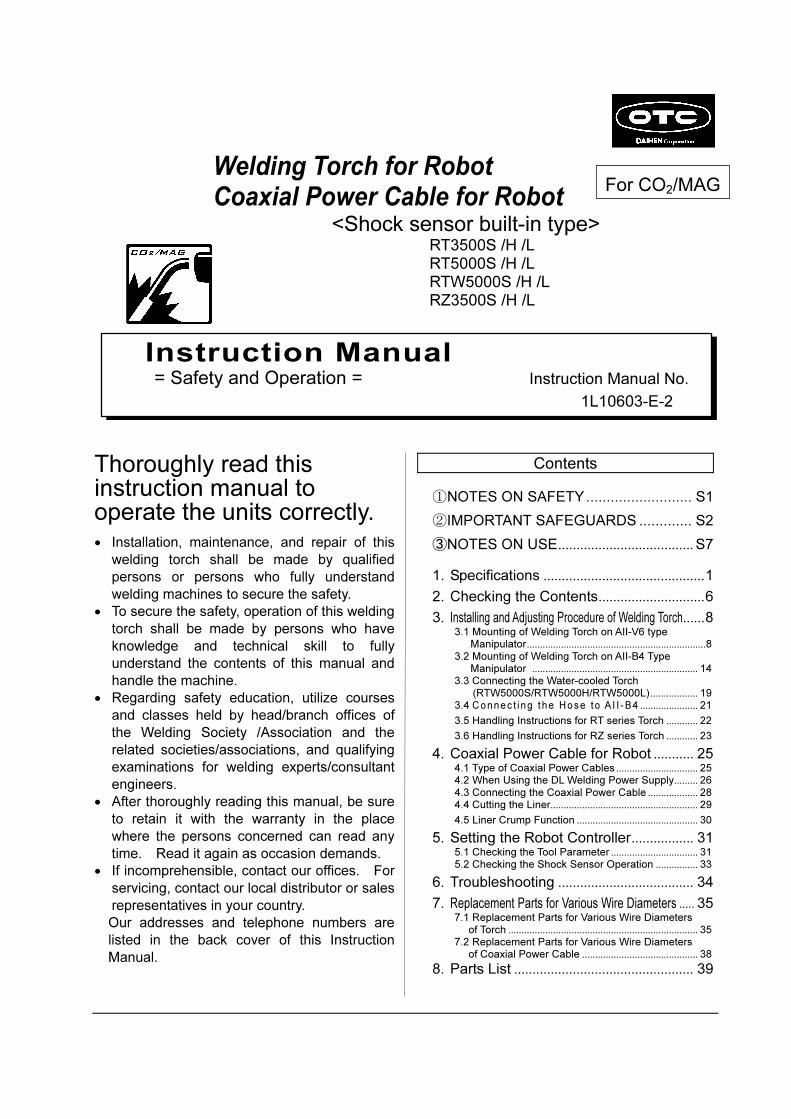
Welding Torch for Robot Coaxial Power Cable for Robot
<Shock sensor built-in type>
RT3500S /H /L
RT5000S /H /L
RTW5000S /H /L
RZ3500S /H /L
Thoroughly read this instruction manual to operate the units correctly. • Installation, maintenance, and repair of this
welding torch shall be made by qualified
persons or persons who fully understand
welding machines to secure the safety.
• To secure the safety, operation of this welding
torch shall be made by persons who have
knowledge and technical skill to fully
understand the contents of this manual and
handle the machine.
• Regarding safety education, utilize courses
and classes held by head/branch offices of
the Welding Society /Association and the
related societies/associations, and qualifying
examinations for welding experts/consultant
engineers.
• After thoroughly reading this manual, be sure
to retain it with the warranty in the place
where the persons concerned can read any
time. Read it again as occasion demands.
• If incomprehensible, contact our offices. For
servicing, contact our local distributor or sales
representatives in your country.
Our addresses and telephone numbers are
listed in the back cover of this Instruction
Manual.
Contents
①NOTES ON SAFETY.......................... S1
②IMPORTANT SAFEGUARDS ............. S2
③NOTES ON USE..................................... S7
1. Specifications ............................................1
2. Checking the Contents.............................6
3. Installing and Adjusting Procedure of Welding Torch......8 3.1 Mounting of Welding Torch on AII-V6 type
Manipulator....................................................................8 3.2 Mounting of Welding Torch on AII-B4 Type
Manipulator ............................................................... 14 3.3 Connecting the Water-cooled Torch
(RTW5000S/RTW5000H/RTW5000L) .................. 19 3.4 C onne c t i ng t he Ho se to A I I - B4 ...................... 21
3.5 Handling Instructions for RT series Torch ............ 22
3.6 Handling Instructions for RZ series Torch ............ 23
4. Coaxial Power Cable for Robot ........... 25 4.1 Type of Coaxial Power Cables ............................... 25 4.2 When Using the DL Welding Power Supply......... 26 4.3 Connecting the Coaxial Power Cable ................... 28 4.4 Cutting the Liner........................................................ 29 4.5 Liner Crump Function .............................................. 30
5. Setting the Robot Controller................. 31 5.1 Checking the Tool Parameter ................................. 31 5.2 Checking the Shock Sensor Operation ................ 33
6. Troubleshooting ..................................... 34
7. Replacement Parts for Various Wire Diameters ..... 35 7.1 Replacement Parts for Various Wire Diameters
of Torch ........................................................................ 35 7.2 Replacement Parts for Various Wire Diameters
of Coaxial Power Cable ............................................ 38 8. Parts List ................................................. 39
Instruction Manual = Safety and Operation = Instruction Manual No.
1L10603-E-2
For CO2/MAG

-S1-
1. Notes on Safety
●Before operating this product, thoroughly read this instruction manual first to operate the product correctly.
●Cautions described in this instruction manual are to prevent you and other people from being injured or damaged by having the product operated correctly and safely.
●Although this product is designed and manufactured in due consideration of safety, carefully follow the notes and cautions described in this manual. Otherwise, there may occur an accident causing serious injury or death.
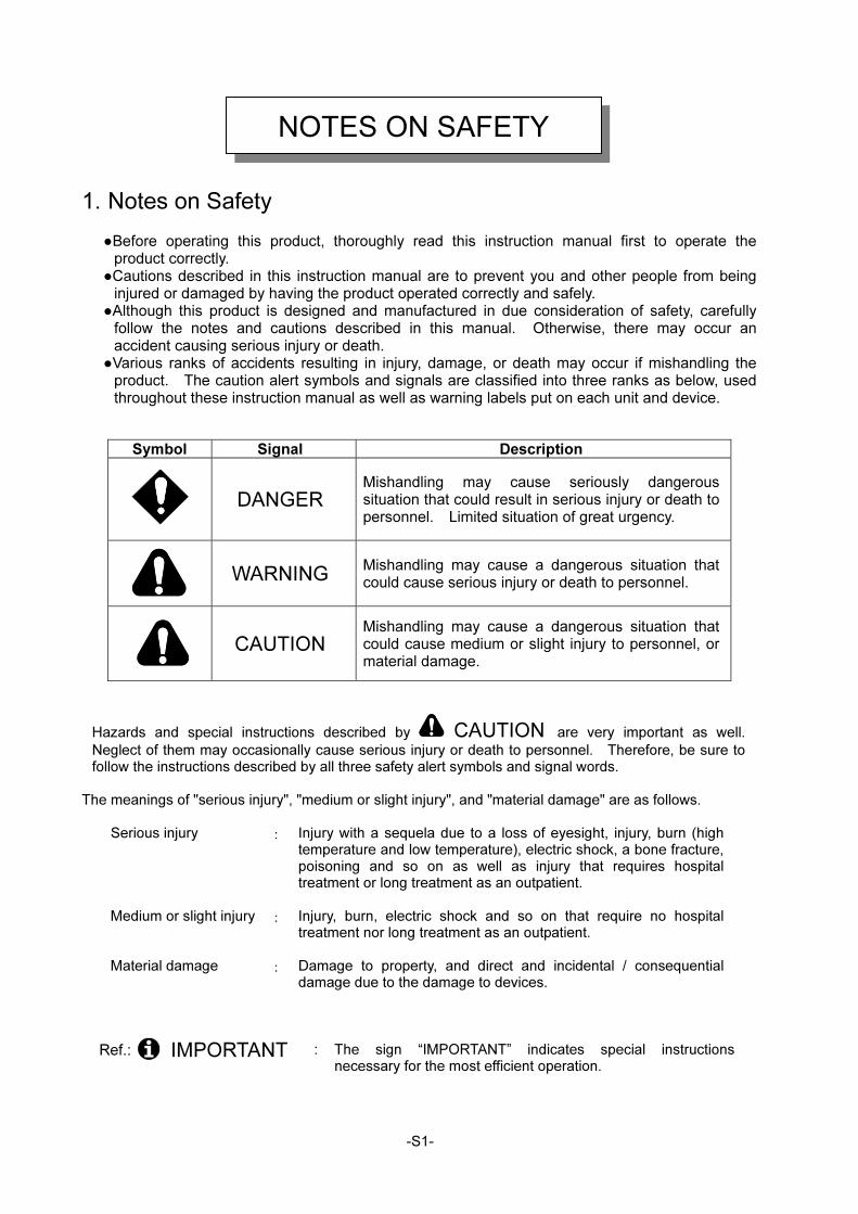
●Various ranks of accidents resulting in injury, damage, or death may occur if mishandling the product. The caution alert symbols and signals are classified into three ranks as below, used throughout these instruction manual as well as warning labels put on each unit and device.
Symbol Signal Description
DANGER
Mishandling may cause seriously dangerous situation that could result in serious injury or death to personnel. Limited situation of great urgency.
WARNING
Mishandling may cause a dangerous situation that could cause serious injury or death to personnel.
CAUTION
Mishandling may cause a dangerous situation that could cause medium or slight injury to personnel, or material damage.
Hazards and special instructions described by CAUTION are very important as well.
Neglect of them may occasionally cause serious injury or death to personnel. Therefore, be sure to follow the instructions described by all three safety alert symbols and signal words.
The meanings of "serious injury", "medium or slight injury", and "material damage" are as follows.
Serious injury : Injury with a sequela due to a loss of eyesight, injury, burn (high temperature and low temperature), electric shock, a bone fracture, poisoning and so on as well as injury that requires hospital treatment or long treatment as an outpatient.
Medium or slight injury : Injury, burn, electric shock and so on that require no hospital treatment nor long treatment as an outpatient.
Material damage : Damage to property, and direct and incidental / consequential damage due to the damage to devices.
Ref.: IMPORTANT : The sign “IMPORTANT” indicates special instructions necessary for the most efficient operation.
NOTES ON SAFETY
-S2-
2. Important Safeguard 2.1 Read, understand, and comply with all safety rules described at the beginning of
each instruction manual in addition to the following ones before starting Arc welding operation.
WARNING Observe the following notices to prevent a serious accident that results in serious injury or death.
1) This torch is designed and manufactured in due consideration of safety, but you must follow
the handling precautions described in this instruction manual. If you fail to do so, there may occur an accident resulting in serious injury or death.
2) Related laws, regulations, and your company's standards should be observed in constructing input power source, selecting an installation area, handling/storing/piping high pressure gas, storing welded products, and disposing wastes.
3) Keep out of the robot operating zone and the welding area. 4) A person with pacemaker should not approach the operating welding machine and the welding
area unless his or her doctor permits. A welding machine generates a magnetic field around it during powered, which will have a bad effect on the pacemaker.
5) Installation, maintenance, and repair of this torch should be performed by qualified personnel or those who fully understand a welding torch for further safety.
6) Operation of this torch should be done by personnel who have knowledge and technical skill to fully understand the contents of this manual and to handle the torch safely.
7) This torch must not be used for purposes other than welding.
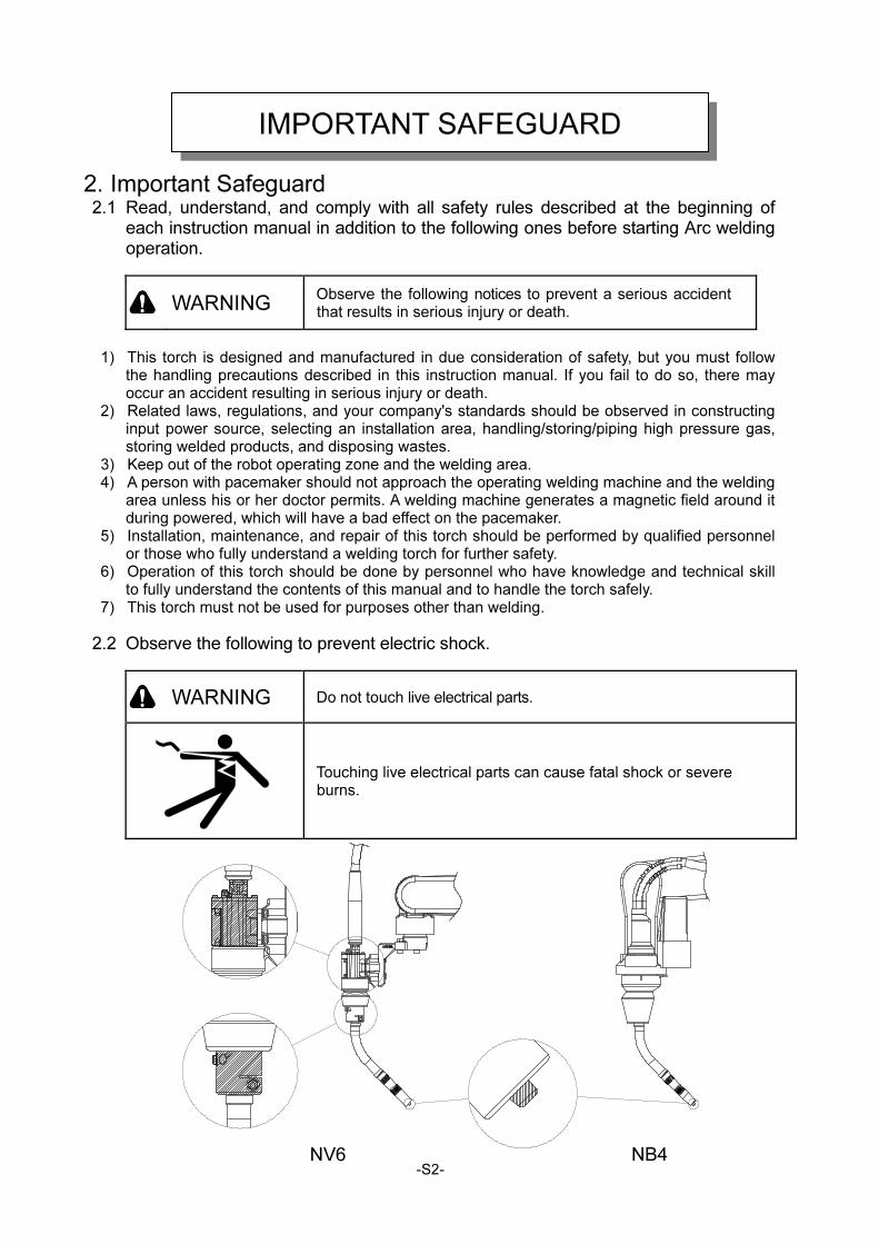
2.2 Observe the following to prevent electric shock.
WARNING Do not touch live electrical parts.
Touching live electrical parts can cause fatal shock or severe burns.
IMPORTANT SAFEGUARD
NV6 NB4
-S3-
1) Only qualified personnel should perform grounding work of the welding power supply and workpiece, or a workpiece and powered peripheral jigs while abiding by domestic regulations.
2) Do not touch live electrical parts. 3) Always wear dry insulating gloves and other body protection. Do not wear torn or wet gloves/
work clothes. 4) Before doing the installation, inspection, maintenance, etc. of this product be sure to turn off
all the input power sources and check, several minutes later, that there is no charging voltage since the condenser and the like may have been recharged.
5) Do not use cables with insufficient capacity, with damage, or with naked conductors. 6) Be sure to tighten the connections of cables and insulate them in order to prevent personnel
from touching those parts easily. 7) DO NOT use a welding machine with its case or cover removed. 8) Secure a firm foothold before initiating work. DO NOT perform work with an unstable
foothold or with a foothold at a height of two meters or above. 9) Make periodic inspection and maintenance. Damaged parts should be repaired before use. 10) Turn off POWER switch when not in use.
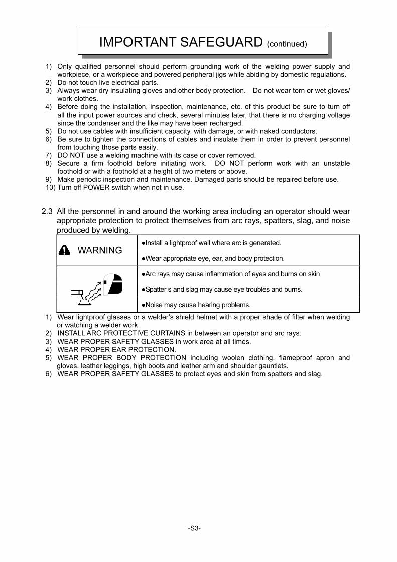
2.3 All the personnel in and around the working area including an operator should wear appropriate protection to protect themselves from arc rays, spatters, slag, and noise produced by welding.
●Install a lightproof wall where arc is generated.
WARNING ●Wear appropriate eye, ear, and body protection.
●Arc rays may cause inflammation of eyes and burns on skin
●Spatter s and slag may cause eye troubles and burns.
●Noise may cause hearing problems.
1) Wear lightproof glasses or a welder’s shield helmet with a proper shade of filter when welding or watching a welder work.
2) INSTALL ARC PROTECTIVE CURTAINS in between an operator and arc rays. 3) WEAR PROPER SAFETY GLASSES in work area at all times. 4) WEAR PROPER EAR PROTECTION. 5) WEAR PROPER BODY PROTECTION including woolen clothing, flameproof apron and
gloves, leather leggings, high boots and leather arm and shoulder gauntlets. 6) WEAR PROPER SAFETY GLASSES to protect eyes and skin from spatters and slag.
IMPORTANT SAFEGUARD (continued)
-S4-
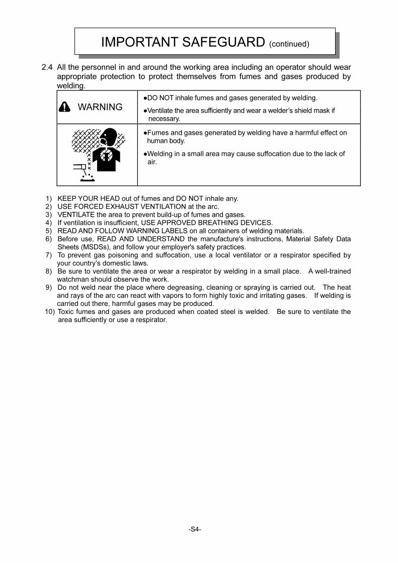
2.4 All the personnel in and around the working area including an operator should wear appropriate protection to protect themselves from fumes and gases produced by welding.
●DO NOT inhale fumes and gases generated by welding.
WARNING ●Ventilate the area sufficiently and wear a welder’s shield mask if necessary.
●Fumes and gases generated by welding have a harmful effect on human body.
●Welding in a small area may cause suffocation due to the lack of air.
1) KEEP YOUR HEAD out of fumes and DO NOT inhale any. 2) USE FORCED EXHAUST VENTILATION at the arc. 3) VENTILATE the area to prevent build-up of fumes and gases. 4) If ventilation is insufficient, USE APPROVED BREATHING DEVICES. 5) READ AND FOLLOW WARNING LABELS on all containers of welding materials. 6) Before use, READ AND UNDERSTAND the manufacture's instructions, Material Safety Data
Sheets (MSDSs), and follow your employer's safety practices. 7) To prevent gas poisoning and suffocation, use a local ventilator or a respirator specified by
your country’s domestic laws. 8) Be sure to ventilate the area or wear a respirator by welding in a small place. A well-trained
watchman should observe the work. 9) Do not weld near the place where degreasing, cleaning or spraying is carried out. The heat
and rays of the arc can react with vapors to form highly toxic and irritating gases. If welding is carried out there, harmful gases may be produced.
10) Toxic fumes and gases are produced when coated steel is welded. Be sure to ventilate the area sufficiently or use a respirator.
IMPORTANT SAFEGUARD (continued)
-S5-
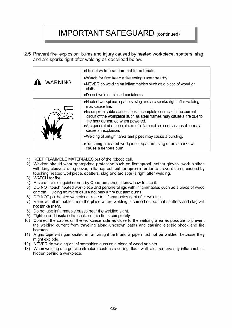
2.5 Prevent fire, explosion, burns and injury caused by heated workpiece, spatters, slag,
and arc sparks right after welding as described below.
●Do not weld near flammable materials.
●Watch for fire: keep a fire extinguisher nearby.
●NEVER do welding on inflammables such as a piece of wood or cloth.
WARNING
●Do not weld on closed containers.
●Heated workpiece, spatters, slag and arc sparks right after welding may cause fire.
●Incomplete cable connections, incomplete contacts in the current circuit of the workpiece such as steel frames may cause a fire due to the heat generated when powered.
●Arc generated on containers of inflammables such as gasoline may cause an explosion.
●Welding of airtight tanks and pipes may cause a bursting.
●Touching a heated workpiece, spatters, slag or arc sparks will cause a serious burn.
1) KEEP FLAMMBLE MATERIALES out of the robotic cell. 2) Welders should wear appropriate protection such as flameproof leather gloves, work clothes
with long sleeves, a leg cover, a flameproof leather apron in order to prevent burns caused by touching heated workpiece, spatters, slag and arc sparks right after welding.
3) WATCH for fire. 4) Have a fire extinguisher nearby Operators should know how to use it. 5) DO NOT touch heated workpiece and peripheral jigs with inflammables such as a piece of wood
or cloth. Doing so might cause not only a fire but also burns. 6) DO NOT put heated workpiece close to inflammables right after welding.. 7) Remove inflammables from the place where welding is carried out so that spatters and slag will
not strike them. 8) Do not use inflammable gases near the welding sight. 9) Tighten and insulate the cable connections completely.
10) Connect the cables on the workpiece side as close to the welding area as possible to prevent the welding current from traveling along unknown paths and causing electric shock and fire hazards.
11) A gas pipe with gas sealed in, an airtight tank and a pipe must not be welded, because they might explode.
12) NEVER do welding on inflammables such as a piece of wood or cloth. 13) When welding a large-size structure such as a ceiling, floor, wall, etc., remove any inflammables
hidden behind a workpiece.
IMPORTANT SAFEGUARD (continued)
-S6-
For reference
PRINCIPAL SAFETY STANDARDS
Safety in Welding and Cutting, ANSI Standard Z49.1, from American Welding Society. Safety and Health Standards, OSHA 29 CFR 1910, from Superintendent of Documents, U.S. Government Printing Office. Recommended Practices for Plasma Arc Cutting, American Welding Society Standard AWS C5.2, from American Welding Society. Recommended Safe Practices for the Preparation for Welding and Cutting of Containers That Have Held Hazardous Substances, American Welding Society Standard AWS F4.1, from American Welding Society. National Electrical Code, NFPA Standard 70, from National Fire Protection Association. Safe Handling of Compressed Gases in Cylinders, CGA Pamphlet P-1, from Compressed Gas Association. Code for Safety in Welding and Cutting, CSA Standard W117.2, from Canadian Standards Association, Standards Sales. Safe Practices For Occupation And Educational Eye And Face Protection, ANSI Standard Z87.1, from American National Standards Institute. Cutting And Welding Processes, NFPA Standard 51B, from National Fire Protection Association.
IMPORTANT SAFEGUARD (continued)
-S7-
3. Notes on Use
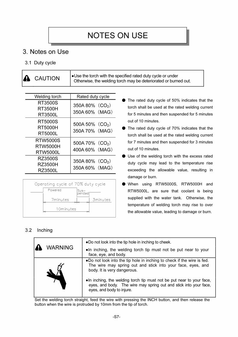
3.1 Duty cycle
CAUTION ●Use the torch with the specified rated duty cycle or under Otherwise, the welding torch may be deteriorated or burned out.
● The rated duty cycle of 50% indicates that the
torch shall be used at the rated welding current
for 5 minutes and then suspended for 5 minutes
out of 10 minutes.
● The rated duty cycle of 70% indicates that the
torch shall be used at the rated welding current
for 7 minutes and then suspended for 3 minutes
out of 10 minutes.
● Use of the welding torch with the excess rated
duty cycle may lead to the temperature rise
exceeding the allowable value, resulting in
damage or burn.
● When using RTW5000S, RTW5000H and
RTW5000L, are sure that coolant is being
supplied with the water tank. Otherwise, the
temperature of welding torch may rise to over
the allowable value, leading to damage or burn.
3.2 Inching
●Do not look into the tip hole in inching to cheek.
WARNING ●In inching, the welding torch tip must not be put near to your face, eye, and body.
●Do not look into the tip hole in inching to check if the wire is fed. The wire may spring out and stick into your face, eyes, and body. It is very dangerous.
●In inching, the welding torch tip must not be put near to your face, eyes, and body. The wire may spring out and stick into your face, eyes, and body to injure.
Set the welding torch straight, feed the wire with pressing the INCH button, and then release the button when the wire is protruded by 10mm from the tip of torch.
NOTES ON USE
Welding torch Rated duty cycle
RT3500S
RT3500H
RT3500L
350A 80%(CO2)
350A 60%(MAG)
RT5000S
RT5000H
RT5000L
500A 50%(CO2)
350A 70%(MAG)
RTW5000S
RTW5000H
RTW5000L
500A 70%(CO2)
400A 60%(MAG)
RZ3500S
RZ3500H
RZ3500L
350A 80%(CO2)
350A 60%(MAG)
-S8-
3.3 Replacement of Parts
CAUTION ●To prevent burns, comply with the following cautions.
● Do not directly touch the high-temperature parts of a nozzle, an electrode and so on. ● When welding, wear suitable protection such as leather gloves for welding. ● Do not replace torch tip elements before they cool off.
CAUTION ●If any parts are damaged, replace them with new ones for further
safety and better quality.
●Be sure to place an order for replacement parts at our sales office or our agency.
CAUTION ●Do not disassemble the shock sensor. If disassembled, gas
leak and malfunction may be caused.
3.4 Coolant
CAUTION
●Be sure to run the coolant for the torch of liquid-cooled specification. Insufficient amount of running water may lead to damage of torch.
3.5 Cable hose
CAUTION
●Never let cable hoses neither touch any heated part of the welded, put something heavy on top nor bend them excessively because the welding torch might become damaged.
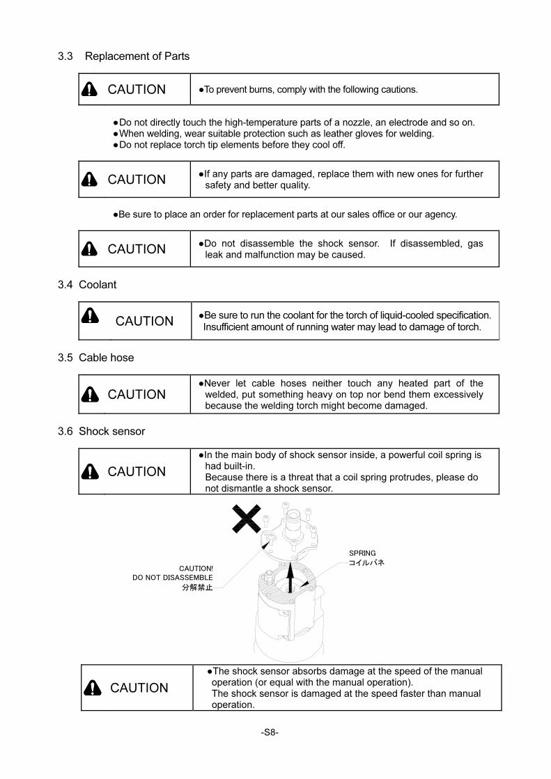
3.6 Shock sensor
CAUTION
●In the main body of shock sensor inside, a powerful coil spring is had built-in. Because there is a threat that a coil spring protrudes, please do not dismantle a shock sensor.
CAUTION
●The shock sensor absorbs damage at the speed of the manual operation (or equal with the manual operation).
The shock sensor is damaged at the speed faster than manual operation.
SPRING
コイルバネCAUTION!
DO NOT DISASSEMBLE
分解禁止
-1-
Thank you for purchasing DAIHEN CO2 /MAG welding torch. Before use, read this instruction manual thoroughly to use the product correctly.
[Note] 1. The contents in this instruction manual are subject to change without prior notice.
2. We have carefully written the standard specifications to eliminate as many errors as possible.
Even if any errors are found in the contents, we are not responsible for any damage resulting
from those errors.
3. No part of this instruction manual may be reproduced or stored in any form without the express
written permission.
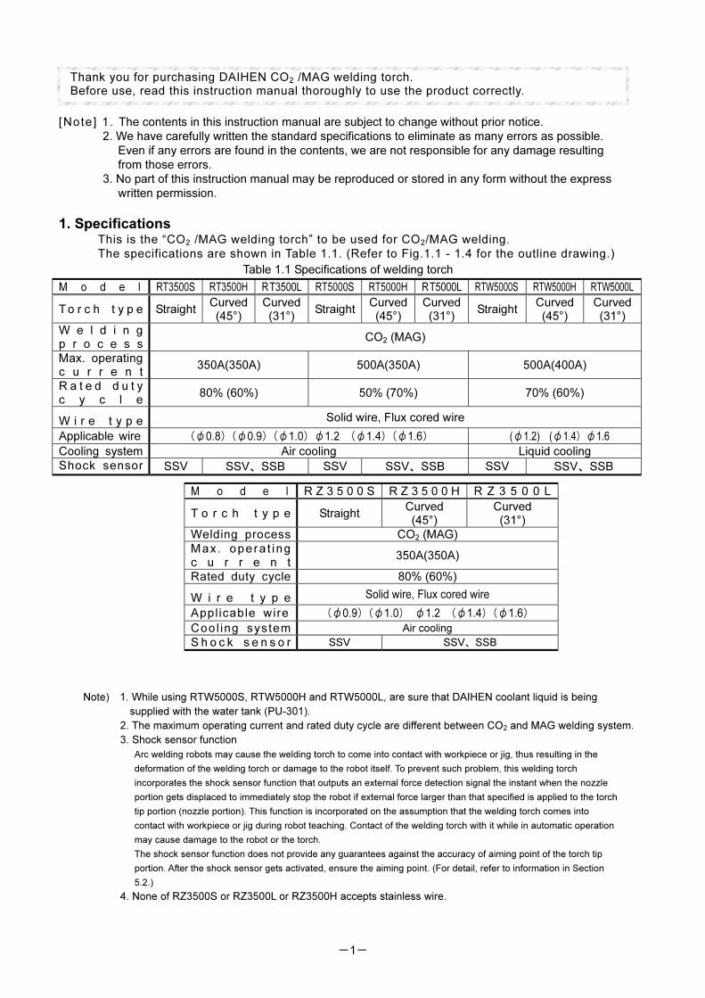
1. Specifications This is the “CO2 /MAG welding torch” to be used for CO2/MAG welding.
The specifications are shown in Table 1.1. (Refer to Fig.1.1 - 1.4 for the outline drawing.)
Table 1.1 Specifications of welding torch
M o d e l RT3500S RT3500H RT3500L RT5000S RT5000H RT5000L RTW5000S RTW5000H RTW5000L
T o r c h t y p e Straight Curved (45°)
Curved(31°)
StraightCurved(45°)
Curved(31°)
Straight Curved (45°)
Curved(31°)
W e l d i n g p r o c e s s
CO2 (MAG)
Max. operating c u r r e n t
350A(350A) 500A(350A) 500A(400A)
R a t e d d u t y c y c l e
80% (60%) 50% (70%) 70% (60%)
W i r e t y p e Solid wire, Flux cored wire
Applicable wire (φ0.8)(φ0.9)(φ1.0)φ1.2 (φ1.4)(φ1.6) (φ1.2) (φ1.4)φ1.6
Cooling system Air cooling Liquid cooling
Shock sensor SSV SSV、SSB SSV SSV、SSB SSV SSV、SSB
Note) 1. While using RTW5000S, RTW5000H and RTW5000L, are sure that DAIHEN coolant liquid is being
supplied with the water tank (PU-301).
2. The maximum operating current and rated duty cycle are different between CO2 and MAG welding system.
3. Shock sensor function
Arc welding robots may cause the welding torch to come into contact with workpiece or jig, thus resulting in the
deformation of the welding torch or damage to the robot itself. To prevent such problem, this welding torch
incorporates the shock sensor function that outputs an external force detection signal the instant when the nozzle
portion gets displaced to immediately stop the robot if external force larger than that specified is applied to the torch
tip portion (nozzle portion). This function is incorporated on the assumption that the welding torch comes into
contact with workpiece or jig during robot teaching. Contact of the welding torch with it while in automatic operation
may cause damage to the robot or the torch.
The shock sensor function does not provide any guarantees against the accuracy of aiming point of the torch tip
portion. After the shock sensor gets activated, ensure the aiming point. (For detail, refer to information in Section
5.2.)
4. None of RZ3500S or RZ3500L or RZ3500H accepts stainless wire.
M o d e l R Z 3 5 0 0 S R Z 3 5 0 0 H R Z 3 5 0 0 L
T o r c h t y p e Straight Curved (45°)
Curved (31°)
Welding process CO2 (MAG)
Max. opera t ing c u r r e n t
350A(350A)
Rated duty cycle 80% (60%)
W i r e t y p e Solid wire, Flux cored wire
Applicable wire (φ0.9)(φ1.0) φ1.2 (φ1.4)(φ1.6)
Cool ing system Air cooling
S h o c k s e n s o r SSV SSV、SSB
-2-
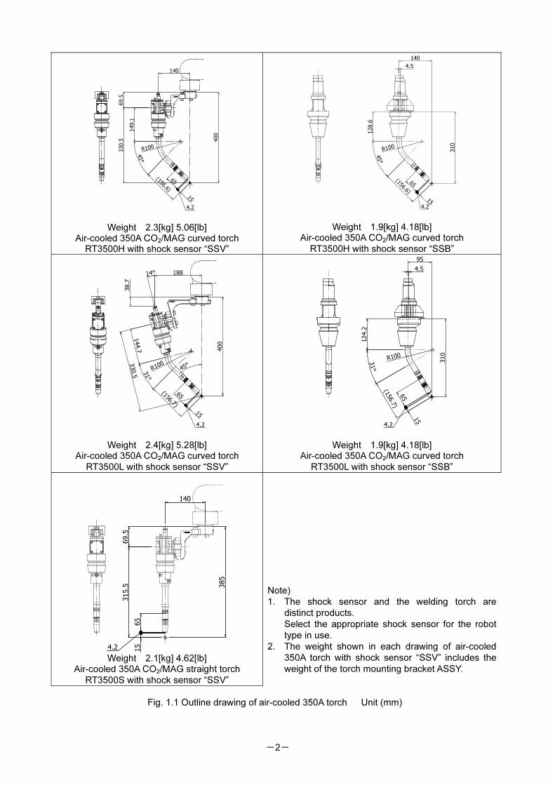
400
69.5
330.5
140
45°
149.1
(156.6)
15
R100
65
4.2
Weight 2.3[kg] 5.06[lb] Air-cooled 350A CO2/MAG curved torch
RT3500H with shock sensor “SSV”
140
4.5
310
45°
(156.6)
15
R100
128.6
65
4.2
Weight 1.9[kg] 4.18[lb] Air-cooled 350A CO2/MAG curved torch
RT3500H with shock sensor “SSB”
14° 188
400
38.7
330.5
31°
144.7
(156.7)
15
R100
45°
65
4.2
Weight 2.4[kg] 5.28[lb] Air-cooled 350A CO2/MAG curved torch
RT3500L with shock sensor “SSV”
95
4.5
310
124.2
31°
(156.7)
R100
65
4.2
15
Weight 1.9[kg] 4.18[lb] Air-cooled 350A CO2/MAG curved torch
RT3500L with shock sensor “SSB”
140
385
69.5
315.5
15
65
4.2 Weight 2.1[kg] 4.62[lb]
Air-cooled 350A CO2/MAG straight torch
RT3500S with shock sensor “SSV”
Note)
1. The shock sensor and the welding torch are
distinct products.
Select the appropriate shock sensor for the robot
type in use.
2. The weight shown in each drawing of air-cooled
350A torch with shock sensor “SSV” includes the
weight of the torch mounting bracket ASSY.
Fig. 1.1 Outline drawing of air-cooled 350A torch Unit (mm)
-3-
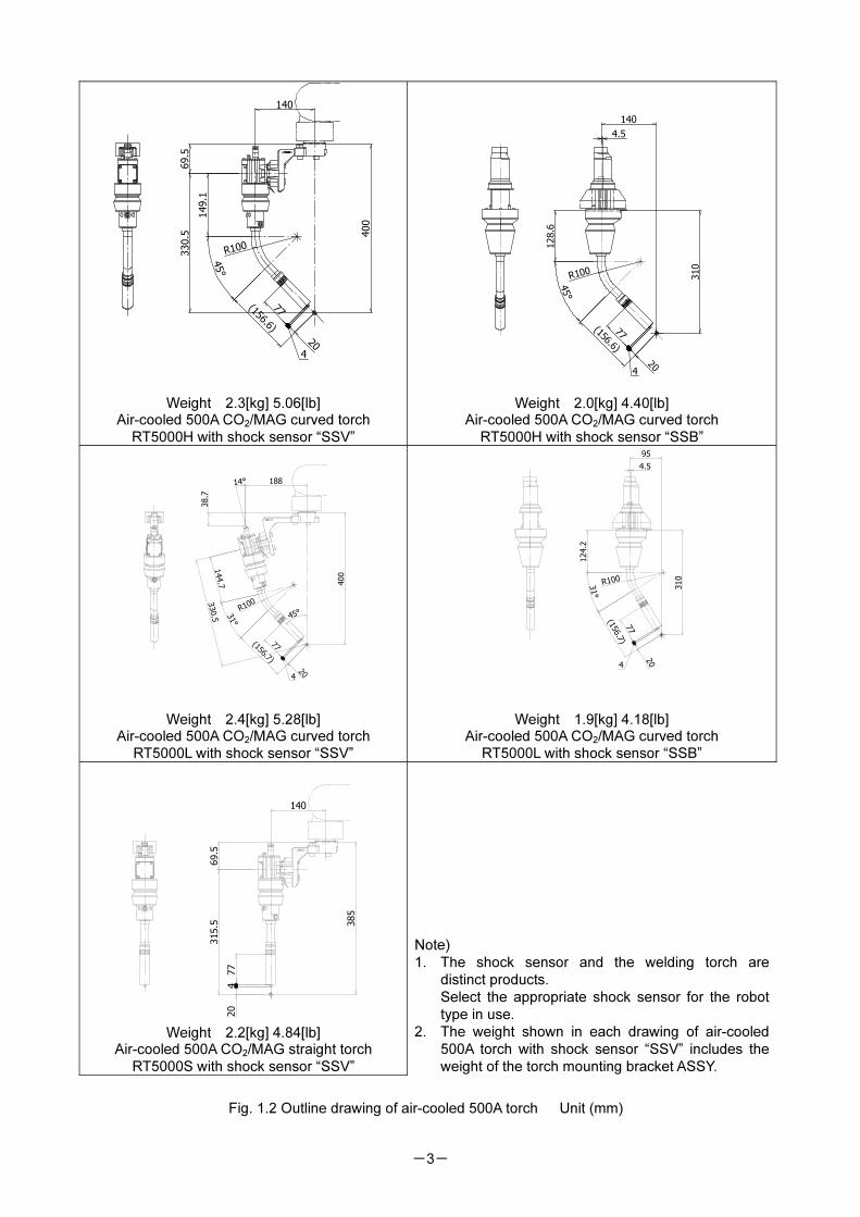
140
400
69.5
149.1
330.5
45°
(156.6)
20
R100
77
4
Weight 2.3[kg] 5.06[lb] Air-cooled 500A CO2/MAG curved torch
RT5000H with shock sensor “SSV”
45°
(156.6)
20
140
4.5
310
R100
128.6
77
4
Weight 2.0[kg] 4.40[lb] Air-cooled 500A CO2/MAG curved torch
RT5000H with shock sensor “SSB”
400
18814°
31°
R100
77
420
(156.7)
144.7
330.5 45
°
38.7
Weight 2.4[kg] 5.28[lb] Air-cooled 500A CO2/MAG curved torch
RT5000L with shock sensor “SSV”
4.5
31°
124.2
310
R100
77
(156.7)
4
20
Weight 1.9[kg] 4.18[lb]
Air-cooled 500A CO2/MAG curved torch
RT5000L with shock sensor “SSB”
140
385
69.5
315.5
20
77
4
Weight 2.2[kg] 4.84[lb]
Air-cooled 500A CO2/MAG straight torch
RT5000S with shock sensor “SSV”
Note)
1. The shock sensor and the welding torch are
distinct products.
Select the appropriate shock sensor for the robot
type in use.
2. The weight shown in each drawing of air-cooled
500A torch with shock sensor “SSV” includes the
weight of the torch mounting bracket ASSY.
Fig. 1.2 Outline drawing of air-cooled 500A torch Unit (mm)
-4-
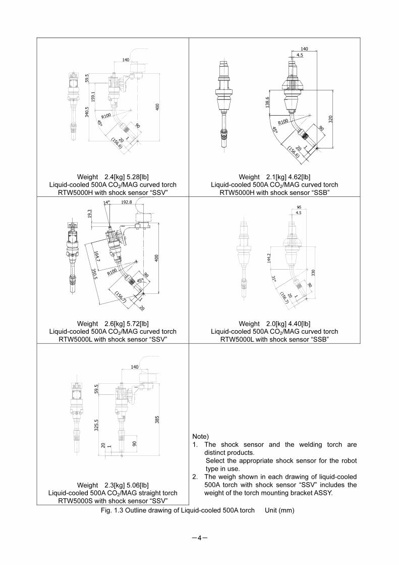
140
59.5
340.5 400
45°
159.1
(156.6)
20
R100
90
1
Weight 2.4[kg] 5.28[lb] Liquid-cooled 500A CO2/MAG curved torch
RTW5000H with shock sensor “SSV”
45°
(156.6)
320
140
4.5
20
R100
90
1
138.6
Weight 2.1[kg] 4.62[lb] Liquid-cooled 500A CO2/MAG curved torch
RTW5000H with shock sensor “SSB”
14° 192.8
350.5
164.7
(156.7)
90R100
400
19.3
1
20
45°
Weight 2.6[kg] 5.72[lb] Liquid-cooled 500A CO2/MAG curved torch
RTW5000L with shock sensor “SSV”
4.5
330
31°
144.2
(156.7)
90
20 1
Weight 2.0[kg] 4.40[lb] Liquid-cooled 500A CO2/MAG curved torch
RTW5000L with shock sensor “SSB”
385
140
59.5
325.5
90
20
1
Weight 2.3[kg] 5.06[lb] Liquid-cooled 500A CO2/MAG straight torch
RTW5000S with shock sensor “SSV”
Note)
1. The shock sensor and the welding torch are
distinct products.
Select the appropriate shock sensor for the robot
type in use.
2. The weigh shown in each drawing of liquid-cooled
500A torch with shock sensor “SSV” includes the
weight of the torch mounting bracket ASSY.
Fig. 1.3 Outline drawing of Liquid-cooled 500A torch Unit (mm)
-5-
400
145
64.5
149.1
335.5
45°
(163.6)
R100
15
78
4
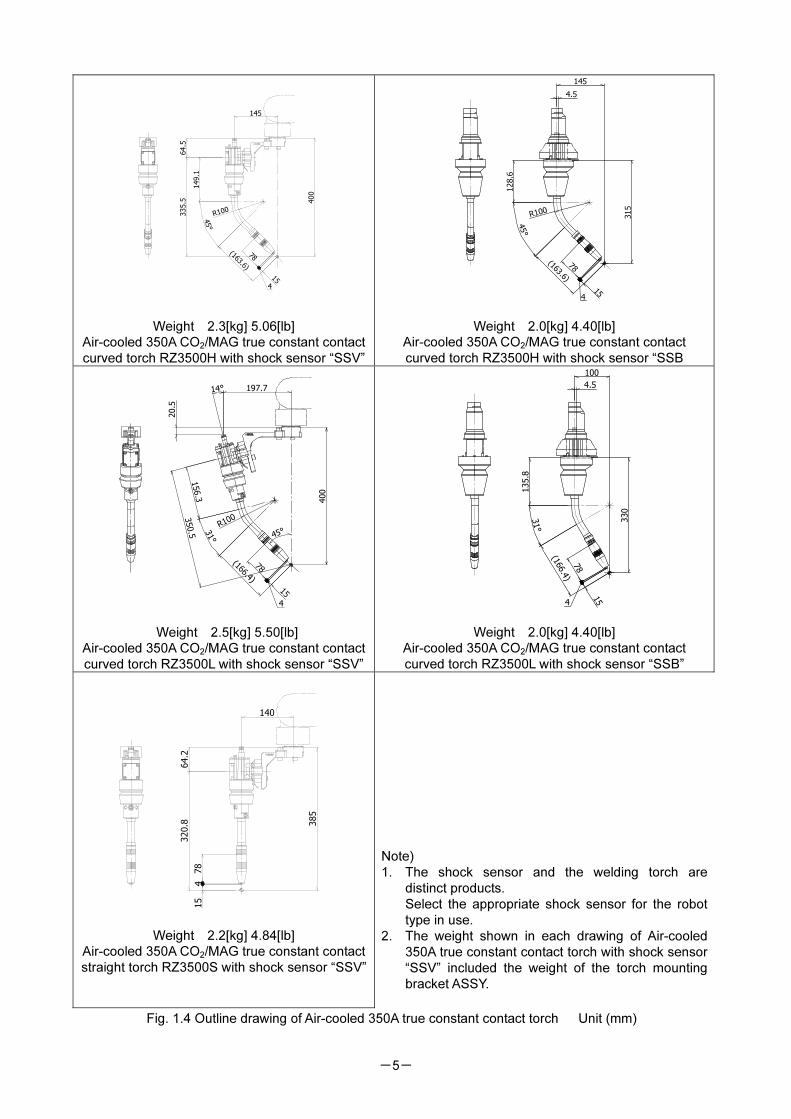
Weight 2.3[kg] 5.06[lb]
Air-cooled 350A CO2/MAG true constant contact
curved torch RZ3500H with shock sensor “SSV”
45°
(163.6)
15
4.5
145
315
R100
128.6
78
4
Weight 2.0[kg] 4.40[lb]
Air-cooled 350A CO2/MAG true constant contact
curved torch RZ3500H with shock sensor “SSB
400
156.3
31°
R100
(166.4)
350.5
45°
14° 197.7
20.5
15
4
78
Weight 2.5[kg] 5.50[lb]
Air-cooled 350A CO2/MAG true constant contact
curved torch RZ3500L with shock sensor “SSV”
330
31°
135.8
78
(166.4)
154
100
4.5
Weight 2.0[kg] 4.40[lb]
Air-cooled 350A CO2/MAG true constant contact
curved torch RZ3500L with shock sensor “SSB”
Weight 2.2[kg] 4.84[lb]
Air-cooled 350A CO2/MAG true constant contact
straight torch RZ3500S with shock sensor “SSV”
Note)
1. The shock sensor and the welding torch are
distinct products.
Select the appropriate shock sensor for the robot
type in use.
2. The weight shown in each drawing of Air-cooled
350A true constant contact torch with shock sensor
“SSV” included the weight of the torch mounting
bracket ASSY.
Fig. 1.4 Outline drawing of Air-cooled 350A true constant contact torch Unit (mm)
478
385
140
64.2
320.8
15
-6-
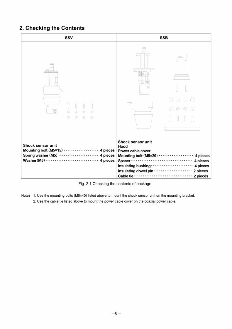
2. Checking the Contents
SSV SSB
Shock sensor unit
Mounting bolt(M5×15)・・・・・・・・・・・・・・・・・・・ 4 pieces
Spring washer(M5)・・・・・・・・・・・・・・・・・・・・・・ 4 pieces
Washer(M5)・・・・・・・・・・・・・・・・・・・・・・・・・・・・・ 4 pieces
Shock sensor unit Hood Power cable cover
Mounting bolt(M5×20)・・・・・・・・・・・・・・・・・・・ 4 pieces
Spacer・・・・・・・・・・・・・・・・・・・・・・・・・・・・・・・・・・ 4 pieces
Insulating bushing・・・・・・・・・・・・・・・・・・・・・・・ 4 pieces
Insulating dowel pin・・・・・・・・・・・・・・・・・・・・・ 2 pieces
Cable tie・・・・・・・・・・・・・・・・・・・・・・・・・・・・・・・・ 2 pieces
Fig. 2.1 Checking the contents of package
Note) 1. Use the mounting bolts (M5×40) listed above to mount the shock sensor unit on the mounting bracket.
2. Use the cable tie listed above to mount the power cable cover on the coaxial power cable.
-7-
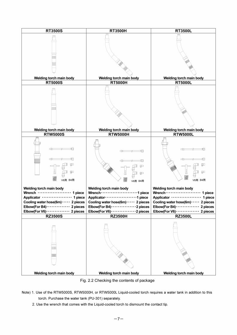
RT3500S RT3500H RT3500L
Welding torch main body
Welding torch main body
Welding torch main body
RT5000S RT5000H RT5000L
Welding torch main body
Welding torch main body
Welding torch main body
RTW5000S RTW5000H RTW5000L
V6用 B4用
Welding torch main body
Wrench ・・・・・・・・・・・・・・・・・・・・ 1 piece
Applicator ・・・・・・・・・・・・・・・・・・ 1 piece
Cooling water hose(6m)・・・・・ 2 pieces
Elbow(For B4)・・・・・・・・・・・・・・ 2 pieces
Elbow(For V6)・・・・・・・・・・・・・・ 2 pieces
V6用 B4用
Welding torch main body
Wrench・・・・・・・・・・・・・・・・・・・・・・1 piece
Applicator・・・・・・・・・・・・・・・・・・・1 piece
Cooling water hose(6m)・・・・・ 2 pieces
Elbow(For B4)・・・・・・・・・・・・・・・2 pieces
Elbow(For V6)・・・・・・・・・・・・・・・2 pieces
V6用 B4用
Welding torch main body
Wrench・・・・・・・・・・・・・・・・・・・・・ 1 piece
Applicator ・・・・・・・・・・・・・・・・・・ 1 piece
Cooling water hose(6m)・・・・・ 2 pieces
Elbow(For B4)・・・・・・・・・・・・・・ 2 pieces
Elbow(For V6)・・・・・・・・・・・・・・ 2 pieces
RZ3500S RZ3500H RZ3500L
Welding torch main body
Welding torch main body
Welding torch main body
Fig. 2.2 Checking the contents of package
Note) 1. Use of the RTW5000S, RTW5000H, or RTW5000L Liquid-cooled torch requires a water tank in addition to this
torch. Purchase the water tank (PU-301) separately.
2. Use the wrench that comes with the Liquid-cooled torch to dismount the contact tip.
-8-
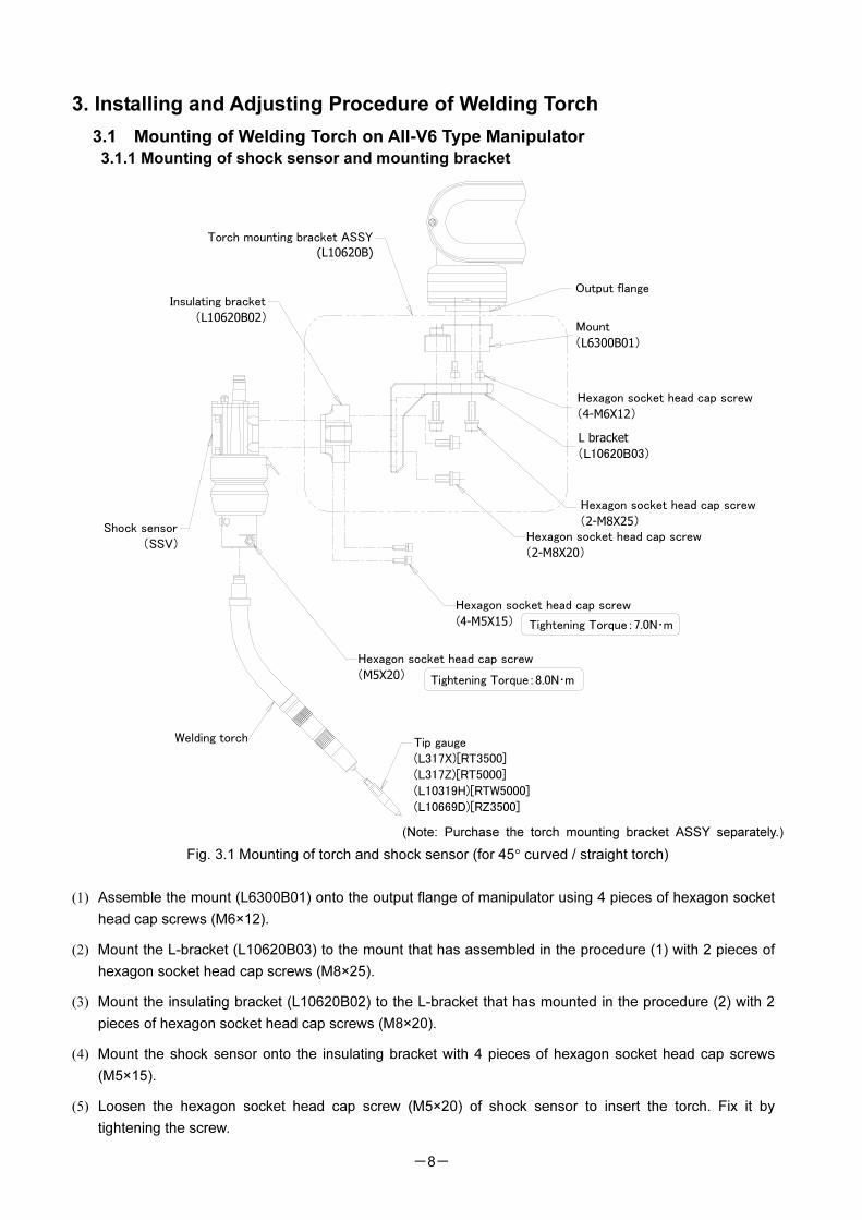
3. Installing and Adjusting Procedure of Welding Torch
3.1 Mounting of Welding Torch on AII-V6 Type Manipulator
3.1.1 Mounting of shock sensor and mounting bracket
(Note: Purchase the torch mounting bracket ASSY separately.)
Fig. 3.1 Mounting of torch and shock sensor (for 45° curved / straight torch)
(1) Assemble the mount (L6300B01) onto the output flange of manipulator using 4 pieces of hexagon socket
head cap screws (M6×12).
(2) Mount the L-bracket (L10620B03) to the mount that has assembled in the procedure (1) with 2 pieces of
hexagon socket head cap screws (M8×25).
(3) Mount the insulating bracket (L10620B02) to the L-bracket that has mounted in the procedure (2) with 2
pieces of hexagon socket head cap screws (M8×20).
(4) Mount the shock sensor onto the insulating bracket with 4 pieces of hexagon socket head cap screws
(M5×15).
(5) Loosen the hexagon socket head cap screw (M5×20) of shock sensor to insert the torch. Fix it by
tightening the screw.
Hexagon socket head cap screw
(4-M6X12)
Output flange
L bracket
(L10620B03)
Hexagon socket head cap screw
(2-M8X20)
Hexagon socket head cap screw
(2-M8X25)
Insulating bracket
(L10620B02)
Torch mounting bracket ASSY
(L10620B)
Mount
(L6300B01)
Hexagon socket head cap screw
(4-M5X15)
Hexagon socket head cap screw
(M5X20)
Shock sensor
(SSV)
Tip gauge
(L317X)[RT3500]
(L317Z)[RT5000]
(L10319H)[RTW5000]
(L10669D)[RZ3500]
Tightening Torque:7.0N・m
Tightening Torque:8.0N・m
Welding torch
-9-
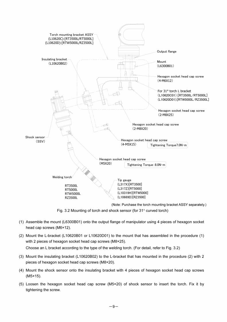
(Note: Purchase the torch mounting bracket ASSY separately.)
Fig. 3.2 Mounting of torch and shock sensor (for 31° curved torch)
(1) Assemble the mount (L6300B01) onto the output flange of manipulator using 4 pieces of hexagon socket
head cap screws (M6×12).
(2) Mount the L-bracket (L10620B01 or L10620D01) to the mount that has assembled in the procedure (1)
with 2 pieces of hexagon socket head cap screws (M8×25).
Choose an L bracket according to the type of the welding torch. (For detail, refer to Fig. 3.2)
(3) Mount the insulating bracket (L10620B02) to the L-bracket that has mounted in the procedure (2) with 2
pieces of hexagon socket head cap screws (M8×20).
(4) Mount the shock sensor onto the insulating bracket with 4 pieces of hexagon socket head cap screws
(M5×15).
(5) Loosen the hexagon socket head cap screw (M5×20) of shock sensor to insert the torch. Fix it by
tightening the screw.
RT3500L
RT5000L
RTW5000L
RZ3500L
Torch mounting bracket ASSY
(L10620C):[RT3500L/RT5000L]
(L10620D):[RTW5000L/RZ3500L]
Welding torch
Hexagon socket head cap screw
(2-M8X20)
Hexagon socket head cap screw
(4-M6X12)
Output flange
For 31° torch L bracket
(L10620C01):[RT3500L/RT5000L]
(L10620D01):[RTW5000L/RZ3500L]
Hexagon socket head cap screw
(2-M8X25)
Mount
(L6300B01)
Tip gauge
(L317X)[RT3500]
(L317Z)[RT5000]
(L10319H)[RTW5000]
(L10669D)[RZ3500]
Insulating bracket
(L10620B02)
Hexagon socket head cap screw
(M5X20)
Shock sensor
(SSV) Hexagon socket head cap screw
(4-M5X15) Tightening Torque7.0N・m
Tightening Torque:8.0N・m
-10-
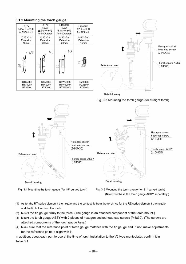
3.1.2 Mounting the torch gauge
Fig. 3.3 Mounting the torch gauge (for straight torch)
Fig. 3.4 Mounting the torch gauge (for 45° curved torch) Fig. 3.5 Mounting the torch gauge (for 31° curved torch)
(Note: Purchase the torch gauge ASSY separately.)
(1) As for the RT series dismount the nozzle and the contact tip from the torch. As for the RZ series dismount the nozzle
and the tip holder from the torch.
(2) Mount the tip gauge firmly to the torch. (The gauge is an attached component of the torch mount.)
(3) Mount the torch gauge ASSY with 2 pieces of hexagon socket head cap screws (M5x30). (The screws are
attached components of the torch gauge Assy.)
(4) Make sure that the reference point of torch gauge matches with the tip gauge end. If not, make adjustments
for the reference point to align with it.
In addition, about each part to use at the time of torch installation to the V6 type manipulator, confirm it in
Table 3.1.
L317X
350A トーチ用
for 350A torch
L317Z
500A
空冷トーチ用
for 500A torch
L10319H
500A
水冷トーチ用
for 500A torch
L10669D
RZ トーチ用
for RZ torch
エクステンション
Extension
15mm
エクステンション
Extension
20mm
エクステンション
Extension
20mm
エクステンション
Extension
15mm
15
15
RT3500S
RT3500H
RT3500L
RT5000S
RT5000H
RT5000L
RTW5000S
RTW5000H
RTW5000L
RZ3500S
RZ3500H
RZ3500L
Torch gauge ASSY
(L6300E)
Hexagon socket
head cap screw
(2-M5X30)
Detail drawing
Reference point
Torch gauge ASSY
(L6300C)
Detail drawing
Reference point
Hexagon socket
head cap screw
(2-M5X30)
Hexagon socket
head cap screw
(2-M5X30)
Torch gauge ASSY
(L10620E)
Detail drawing
Reference point
-11-
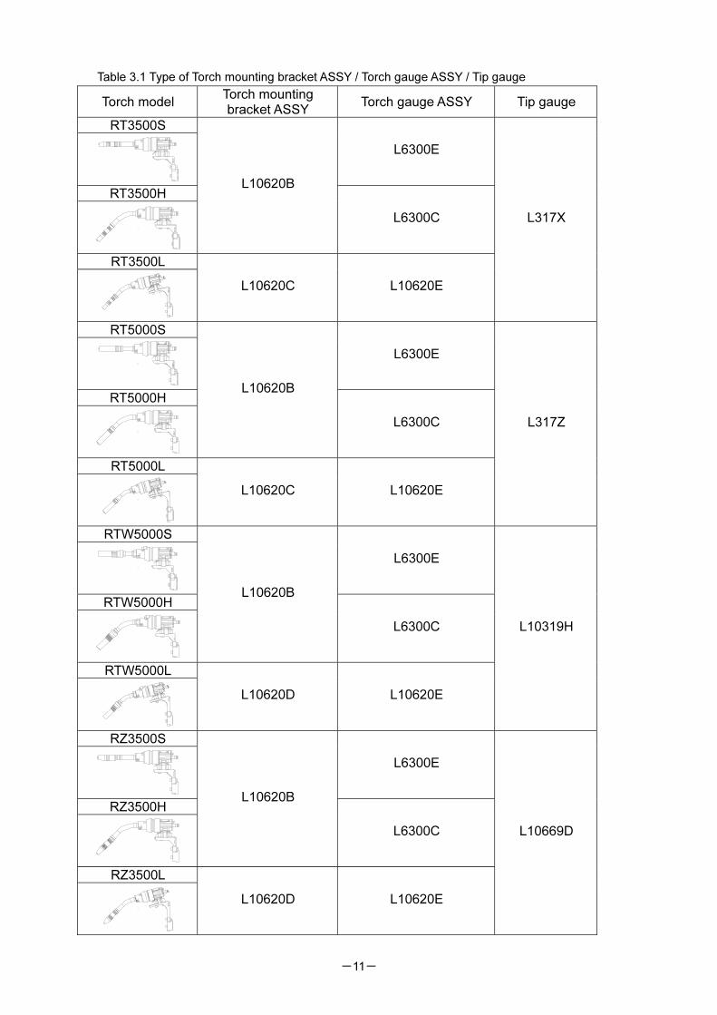
Table 3.1 Type of Torch mounting bracket ASSY / Torch gauge ASSY / Tip gauge
Torch model Torch mounting bracket ASSY
Torch gauge ASSY Tip gauge
RT3500S
L6300E
RT3500H
L10620B
L6300C
RT3500L
L10620C L10620E
L317X
RT5000S
L6300E
RT5000H
L10620B
L6300C
RT5000L
L10620C L10620E
L317Z
RTW5000S
L6300E
RTW5000H
L10620B
L6300C
RTW5000L
L10620D L10620E
L10319H
RZ3500S
L6300E
RZ3500H
L10620B
L6300C
RZ3500L
L10620D L10620E
L10669D
-12-
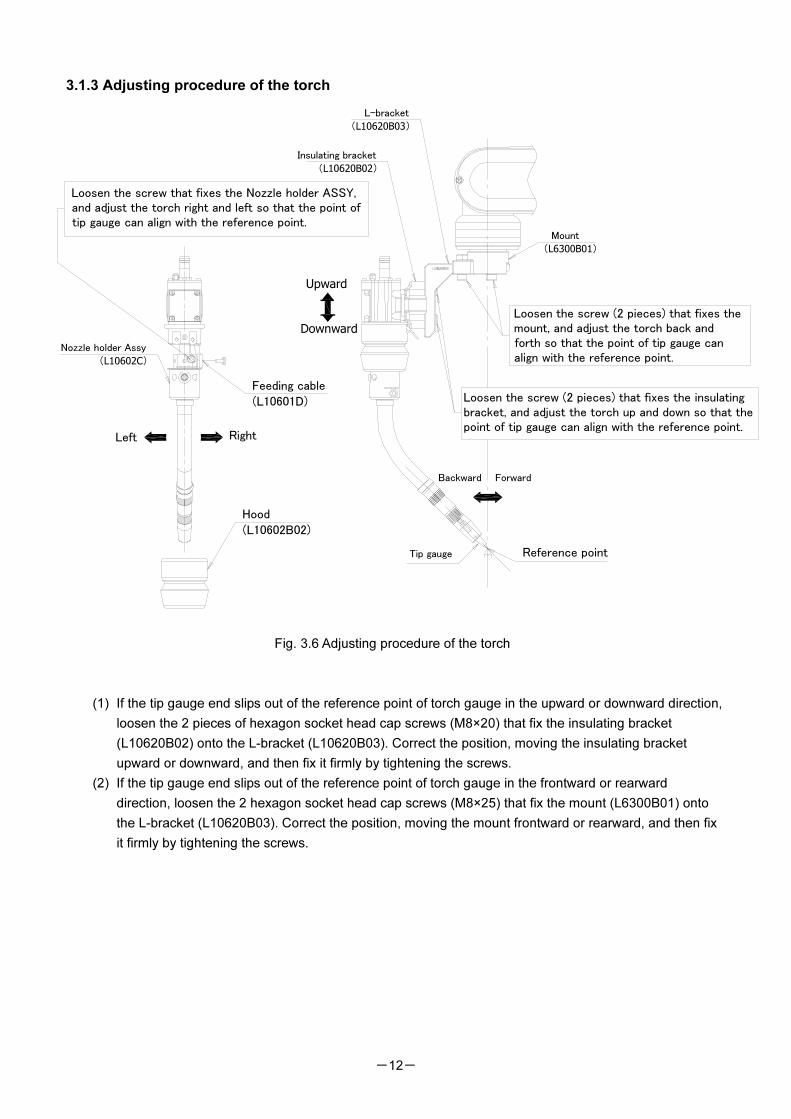
3.1.3 Adjusting procedure of the torch
Fig. 3.6 Adjusting procedure of the torch
(1) If the tip gauge end slips out of the reference point of torch gauge in the upward or downward direction,
loosen the 2 pieces of hexagon socket head cap screws (M8×20) that fix the insulating bracket
(L10620B02) onto the L-bracket (L10620B03). Correct the position, moving the insulating bracket
upward or downward, and then fix it firmly by tightening the screws.
(2) If the tip gauge end slips out of the reference point of torch gauge in the frontward or rearward
direction, loosen the 2 hexagon socket head cap screws (M8×25) that fix the mount (L6300B01) onto
the L-bracket (L10620B03). Correct the position, moving the mount frontward or rearward, and then fix
it firmly by tightening the screws.
Loosen the screw (2 pieces) that fixes the
mount, and adjust the torch back and
forth so that the point of tip gauge can
align with the reference point.
Reference pointTip gauge
Loosen the screw (2 pieces) that fixes the insulating
bracket, and adjust the torch up and down so that the
point of tip gauge can align with the reference point.
Insulating bracket
(L10620B02)
Mount
(L6300B01)
Upward
Downward
Loosen the screw that fixes the Nozzle holder ASSY,
and adjust the torch right and left so that the point of
tip gauge can align with the reference point.
L-bracket
(L10620B03)
Nozzle holder Assy
(L10602C)
Hood
(L10602B02)
Feeding cable
(L10601D)
Backward Forward
RightLeft
-13-
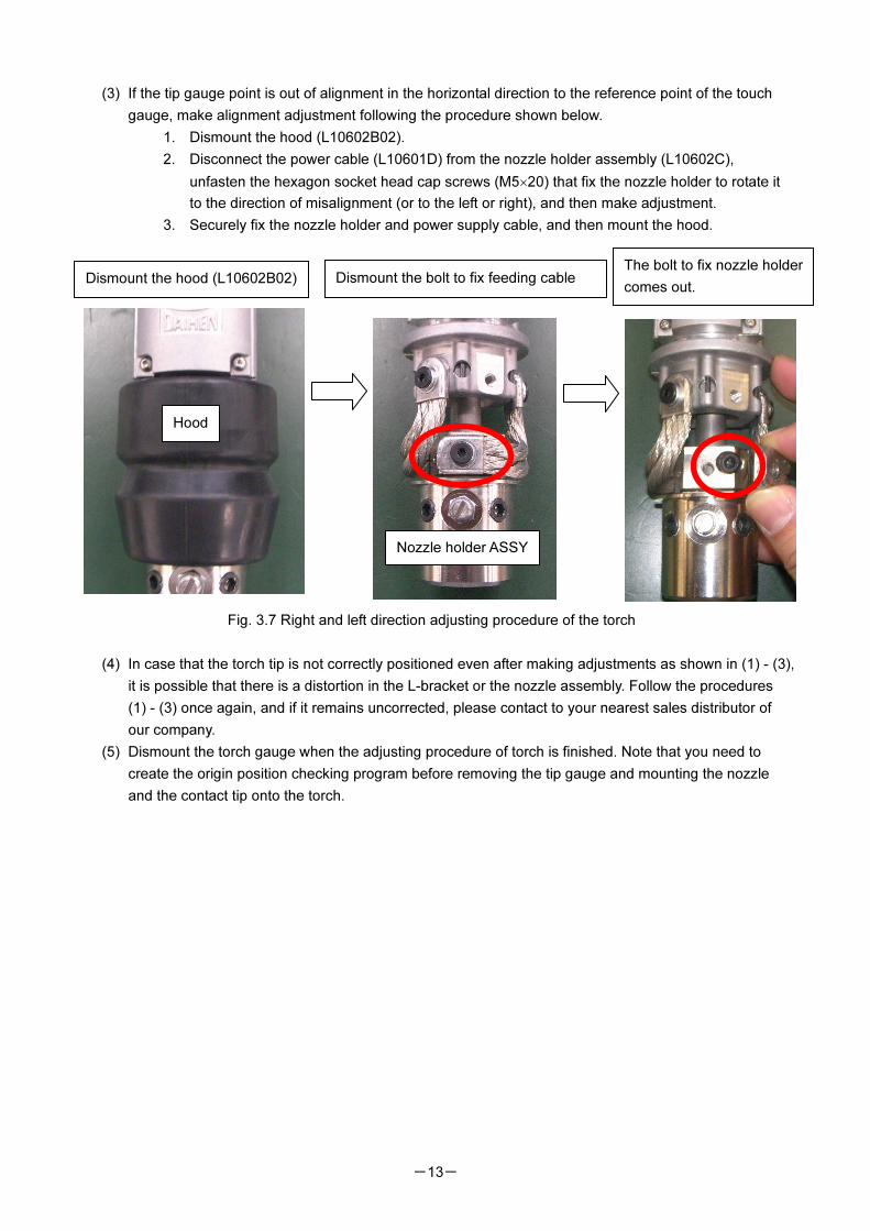
(3) If the tip gauge point is out of alignment in the horizontal direction to the reference point of the touch
gauge, make alignment adjustment following the procedure shown below.
1. Dismount the hood (L10602B02).
2. Disconnect the power cable (L10601D) from the nozzle holder assembly (L10602C),
unfasten the hexagon socket head cap screws (M5×20) that fix the nozzle holder to rotate it
to the direction of misalignment (or to the left or right), and then make adjustment.
3. Securely fix the nozzle holder and power supply cable, and then mount the hood.
Fig. 3.7 Right and left direction adjusting procedure of the torch
(4) In case that the torch tip is not correctly positioned even after making adjustments as shown in (1) - (3),
it is possible that there is a distortion in the L-bracket or the nozzle assembly. Follow the procedures
(1) - (3) once again, and if it remains uncorrected, please contact to your nearest sales distributor of
our company.
(5) Dismount the torch gauge when the adjusting procedure of torch is finished. Note that you need to
create the origin position checking program before removing the tip gauge and mounting the nozzle
and the contact tip onto the torch.
Dismount the hood (L10602B02) Dismount the bolt to fix feeding cable The bolt to fix nozzle holder
comes out.
Hood
Nozzle holder ASSY
-14-
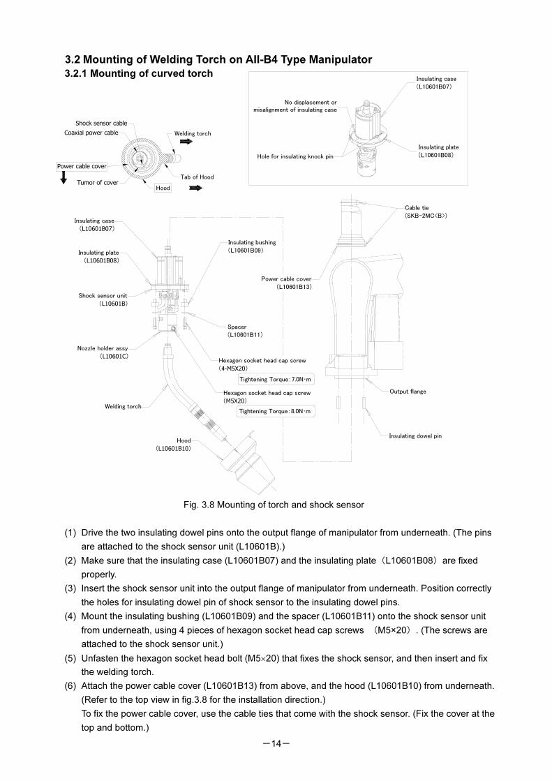
3.2 Mounting of Welding Torch on AII-B4 Type Manipulator
3.2.1 Mounting of curved torch
Fig. 3.8 Mounting of torch and shock sensor
(1) Drive the two insulating dowel pins onto the output flange of manipulator from underneath. (The pins
are attached to the shock sensor unit (L10601B).)
(2) Make sure that the insulating case (L10601B07) and the insulating plate(L10601B08)are fixed
properly.
(3) Insert the shock sensor unit into the output flange of manipulator from underneath. Position correctly
the holes for insulating dowel pin of shock sensor to the insulating dowel pins.
(4) Mount the insulating bushing (L10601B09) and the spacer (L10601B11) onto the shock sensor unit
from underneath, using 4 pieces of hexagon socket head cap screws (M5×20). (The screws are
attached to the shock sensor unit.)
(5) Unfasten the hexagon socket head bolt (M5×20) that fixes the shock sensor, and then insert and fix
the welding torch.
(6) Attach the power cable cover (L10601B13) from above, and the hood (L10601B10) from underneath.
(Refer to the top view in fig.3.8 for the installation direction.)
To fix the power cable cover, use the cable ties that come with the shock sensor. (Fix the cover at the
top and bottom.)
Hexagon socket head cap screw
(4-M5X20)
Shock sensor unit
(L10601B)
Welding torch
Nozzle holder assy
(L10601C)
Hood
(L10601B10)
Spacer
(L10601B11)
Insulating bushing
(L10601B09)Insulating plate
(L10601B08)
Insulating case
(L10601B07)
Output flange
Power cable cover
(L10601B13)
Insulating dowel pin
Hexagon socket head cap screw
(M5X20)
No displacement or
misalignment of insulating case
Insulating plate
(L10601B08)
Insulating case
(L10601B07)
Hole for insulating knock pin
Shock sensor cable
Coaxial power cable
Hood
Power cable cover
Welding torch
Tab of HoodTumor of cover
Cable tie
(SKB-2MC<B>)
Tightening Torque:7.0N・m
Tightening Torque:8.0N・m
-15-
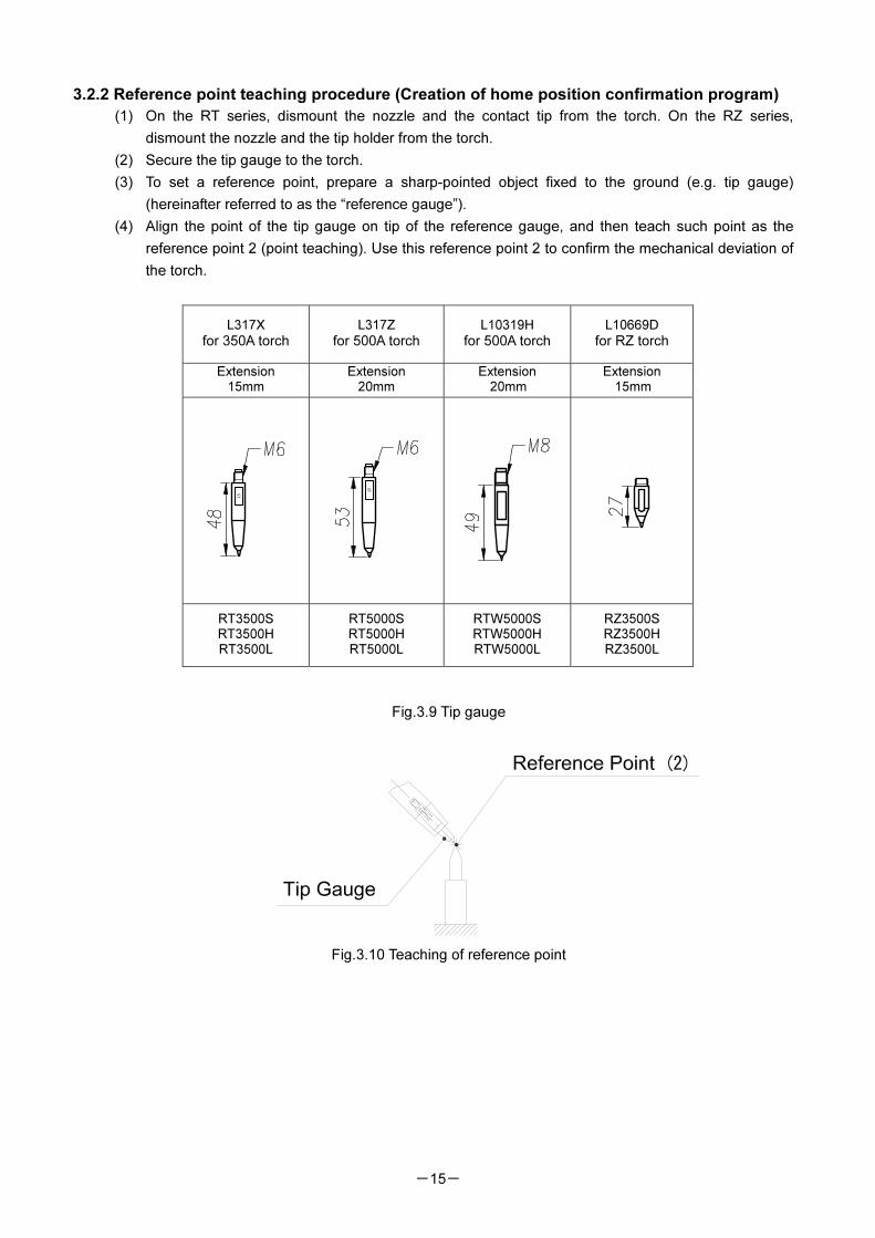
3.2.2 Reference point teaching procedure (Creation of home position confirmation program)
(1) On the RT series, dismount the nozzle and the contact tip from the torch. On the RZ series,
dismount the nozzle and the tip holder from the torch.
(2) Secure the tip gauge to the torch.
(3) To set a reference point, prepare a sharp-pointed object fixed to the ground (e.g. tip gauge)
(hereinafter referred to as the “reference gauge”).
(4) Align the point of the tip gauge on tip of the reference gauge, and then teach such point as the
reference point 2 (point teaching). Use this reference point 2 to confirm the mechanical deviation of
the torch.
Fig.3.9 Tip gauge
Fig.3.10 Teaching of reference point
L317X
for 350A torch
L317Z
for 500A torch
L10319H
for 500A torch
L10669D
for RZ torch
Extension 15mm
Extension 20mm
Extension 20mm
Extension 15mm
15
15
RT3500S RT3500H RT3500L
RT5000S RT5000H RT5000L
RTW5000S RTW5000H RTW5000L
RZ3500S RZ3500H RZ3500L
Tip Gauge
-16-
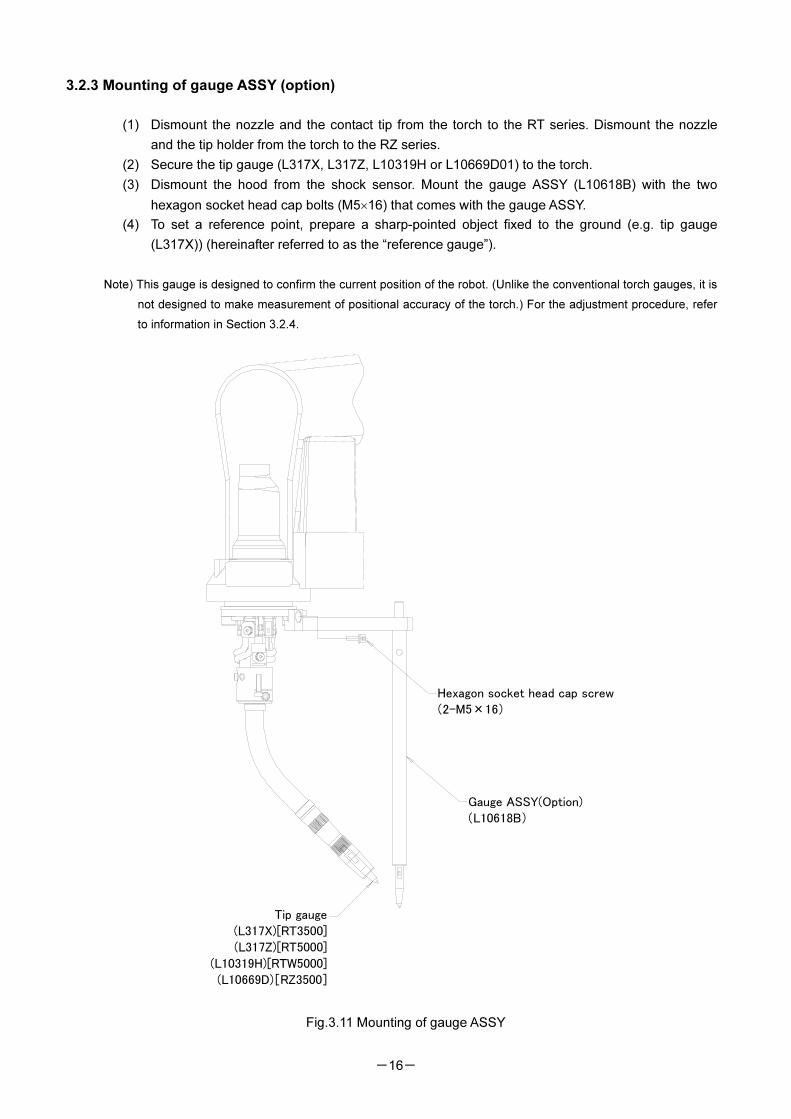
3.2.3 Mounting of gauge ASSY (option)
(1) Dismount the nozzle and the contact tip from the torch to the RT series. Dismount the nozzle
and the tip holder from the torch to the RZ series.
(2) Secure the tip gauge (L317X, L317Z, L10319H or L10669D01) to the torch.
(3) Dismount the hood from the shock sensor. Mount the gauge ASSY (L10618B) with the two
hexagon socket head cap bolts (M5×16) that comes with the gauge ASSY.
(4) To set a reference point, prepare a sharp-pointed object fixed to the ground (e.g. tip gauge
(L317X)) (hereinafter referred to as the “reference gauge”).
Note) This gauge is designed to confirm the current position of the robot. (Unlike the conventional torch gauges, it is
not designed to make measurement of positional accuracy of the torch.) For the adjustment procedure, refer
to information in Section 3.2.4.
Fig.3.11 Mounting of gauge ASSY
Hexagon socket head cap screw
(2-M5×16)
Gauge ASSY(Option)
(L10618B)
Tip gauge
(L317X)[RT3500]
(L317Z)[RT5000]
(L10319H)[RTW5000]
(L10669D)[RZ3500]
-17-
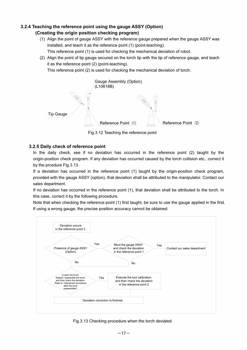
3.2.4 Teaching the reference point using the gauge ASSY (Option)
(Creating the origin position checking program)
(1) Align the point of gauge ASSY with the reference gauge prepared when the gauge ASSY was
installed, and teach it as the reference point (1) (point-teaching).
This reference point (1) is used for checking the mechanical deviation of robot.
(2) Align the point of tip gauge secured on the torch tip with the tip of reference gauge, and teach
it as the reference point (2) (point-teaching).
This reference point (2) is used for checking the mechanical deviation of torch.
Fig.3.12 Teaching the reference point
3.2.5 Daily check of reference point
In the daily check, see if no deviation has occurred in the reference point (2) taught by the
origin-position check program. If any deviation has occurred caused by the torch collision etc., correct it
by the prcedure Fig.3.13.
If a deviation has occurred in the reference point (1) taught by the origin-position check program,
provided with the gauge ASSY (option), that deviation shall be attributed to the manipulator. Contact our
sales department.
If no deviation has occurred in the reference point (1), that deviation shall be attributed to the torch. In
this case, correct it by the following procedure.
Note that when checking the reference point (1) first taught, be sure to use the gauge applied in the first.
If using a wrong gauge, the precise position accuracy cannot be obtained.
Fig.3.13 Checking procedure when the torch deviated
(L10618B)
Reference Point (1) Reference Point (2)
Deviation occurs
in the reference point 2.
Contact our sales department
Mout the gauge ASSY
and check the deviation
in the reference point 1
Yes
No
Loosen the torch-
fixepart, reassenble the torch,
and then check the deviation.
Refer to "Adjustment procedure
after the torch
reassembled".
Yes Execute the tool calibration,
and then check the deviation
in the reference point 2
Deviation correction is finished.
Presence of gauge ASSY
(Option)
Yes
No
-18-
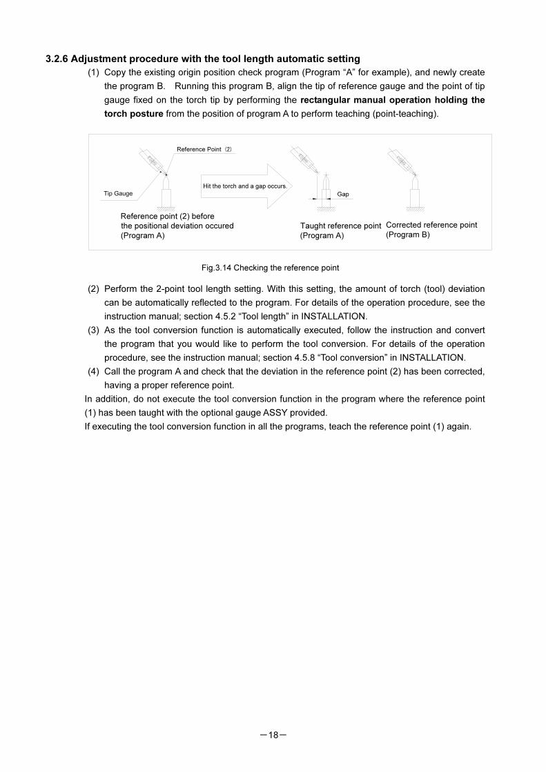
3.2.6 Adjustment procedure with the tool length automatic setting
(1) Copy the existing origin position check program (Program “A” for example), and newly create
the program B. Running this program B, align the tip of reference gauge and the point of tip
gauge fixed on the torch tip by performing the rectangular manual operation holding the
torch posture from the position of program A to perform teaching (point-teaching).
Fig.3.14 Checking the reference point
(2) Perform the 2-point tool length setting. With this setting, the amount of torch (tool) deviation
can be automatically reflected to the program. For details of the operation procedure, see the
instruction manual; section 4.5.2 “Tool length” in INSTALLATION.
(3) As the tool conversion function is automatically executed, follow the instruction and convert
the program that you would like to perform the tool conversion. For details of the operation
procedure, see the instruction manual; section 4.5.8 “Tool conversion” in INSTALLATION.
(4) Call the program A and check that the deviation in the reference point (2) has been corrected,
having a proper reference point.
In addition, do not execute the tool conversion function in the program where the reference point
(1) has been taught with the optional gauge ASSY provided.
If executing the tool conversion function in all the programs, teach the reference point (1) again.
Reference Point (2)
Reference point (2) before
the positional deviation occured
(Program A)
Taught reference point
(Program A)
Gap
Corrected reference point
(Program B)
Hit the torch and a gap occurs.
-19-
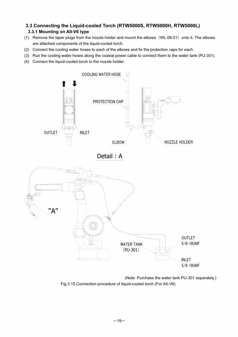
3.3 Connecting the Liquid-cooled Torch (RTW5000S, RTW5000H, RTW5000L)
3.3.1 Mounting on AII-V6 type
(1) Remove the taper plugs from the nozzle holder and mount the elbows(WL-06-01)onto it. The elbows
are attached components of the liquid-cooled torch.
(2) Connect the cooling water hoses to each of the elbows and fix the protection caps for each.
(3) Run the cooling water hoses along the coaxial power cable to connect them to the water tank (PU-301).
(4) Connect the liquid-cooled torch to the nozzle holder.
(Note: Purchase the water tank PU-301 separately.)
Fig.3.15 Connection procedure of liquid-cooled torch (For AII-V6)
Detail : A
"A"
-20-
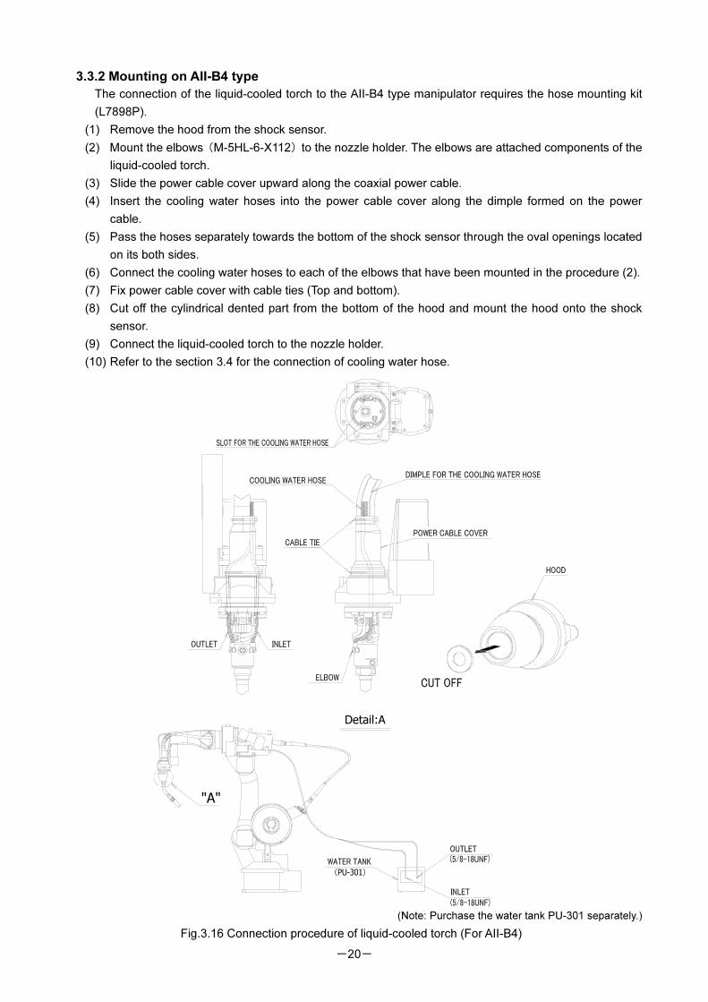
3.3.2 Mounting on AII-B4 type
The connection of the liquid-cooled torch to the AII-B4 type manipulator requires the hose mounting kit
(L7898P).
(1) Remove the hood from the shock sensor.
(2) Mount the elbows(M-5HL-6-X112)to the nozzle holder. The elbows are attached components of the
liquid-cooled torch.
(3) Slide the power cable cover upward along the coaxial power cable.
(4) Insert the cooling water hoses into the power cable cover along the dimple formed on the power
cable.
(5) Pass the hoses separately towards the bottom of the shock sensor through the oval openings located
on its both sides.
(6) Connect the cooling water hoses to each of the elbows that have been mounted in the procedure (2).
(7) Fix power cable cover with cable ties (Top and bottom).
(8) Cut off the cylindrical dented part from the bottom of the hood and mount the hood onto the shock
sensor.
(9) Connect the liquid-cooled torch to the nozzle holder.
(10) Refer to the section 3.4 for the connection of cooling water hose.
(Note: Purchase the water tank PU-301 separately.)
Fig.3.16 Connection procedure of liquid-cooled torch (For AII-B4)
Detail:A
"A"

-21-
3.4 Connecting the Hose to AII-B4 1. Connect the hose to the torch along with the coaxial power cable.
2. Bind up the hose and coaxial power cable with a spiral tube.
Connect spiral tubes to the W/F side as shown with *1 to *3.
[Caution] Slacken off the portions marked with“*”in Fig.3.17.
3. Adjust the slack in the tube.
(1) Make the robot posture upright and horizontal.
(2) Rotate the 6th axis to in the maximum (soft limit), and check that no stress is applied to the hose.
[Both +/- side]
(3) Rotate the 6th axis to in the maximum (soft limit) in either + or – side, and 4
th axis in the other side of
the 6th axis to the maximum (soft limit), and then check that no stress is applied the hose.
(4) Rotate both the 4th and 6
th axis to the maximum (soft limit) respectively in the other side of the above
operation (3), and check that no stress is applied to the hose.
4. Check the slack of hose, and secure the spiral tube at its end with a cable tie.
5. Bind the hose and coaxial power cable on the W/F side with a cable tie.
6. Use cable ties that come with the shock sensor to fix the top
end of the power cable cover together with the coaxial power
cable, shock sensor cable and hose.
Fig.3.17 Connection of hose [AII-B4]
-22-
3.5 Handling Instructions for RT series Torch (1) Be sure to install an orifice. Installation of the orifice is essential, which prevents the short
circuit likely to happen between the nozzle and torch body, and also avoids turbulence of the
shield gas.
(2) Remove the spatter adhered to the nozzle and contact tip before it gets deposited.
(3) Be sure to use the DAIHEN genuine tip. Use of a worn-out tip with an enlarged diameter
causes conduction defect and wire deflection, which results in unstable Arc and aiming
deviation. Therefore, replace the tip accordingly before it gets used up.
(4) Gas flow shall be 15 l/min or more...
(5) Clean up the inside of liner (included in the coaxial power cable) and of outlet guide with
compressed air or others once in 10 days. Otherwise, deposit of sludge and dust will cause
defective wire feeding, which leads to poor welding performance.
(6) When the wire is stuck at the tip end, the wire will buckle in the liner or be cut in the feed roll.
If keeping wire feed performance under such a condition, feeding failure or Arc shortage may
occur. To prevent this, remove the wire between the feed roll and tip end first, and then insert
a new wire.
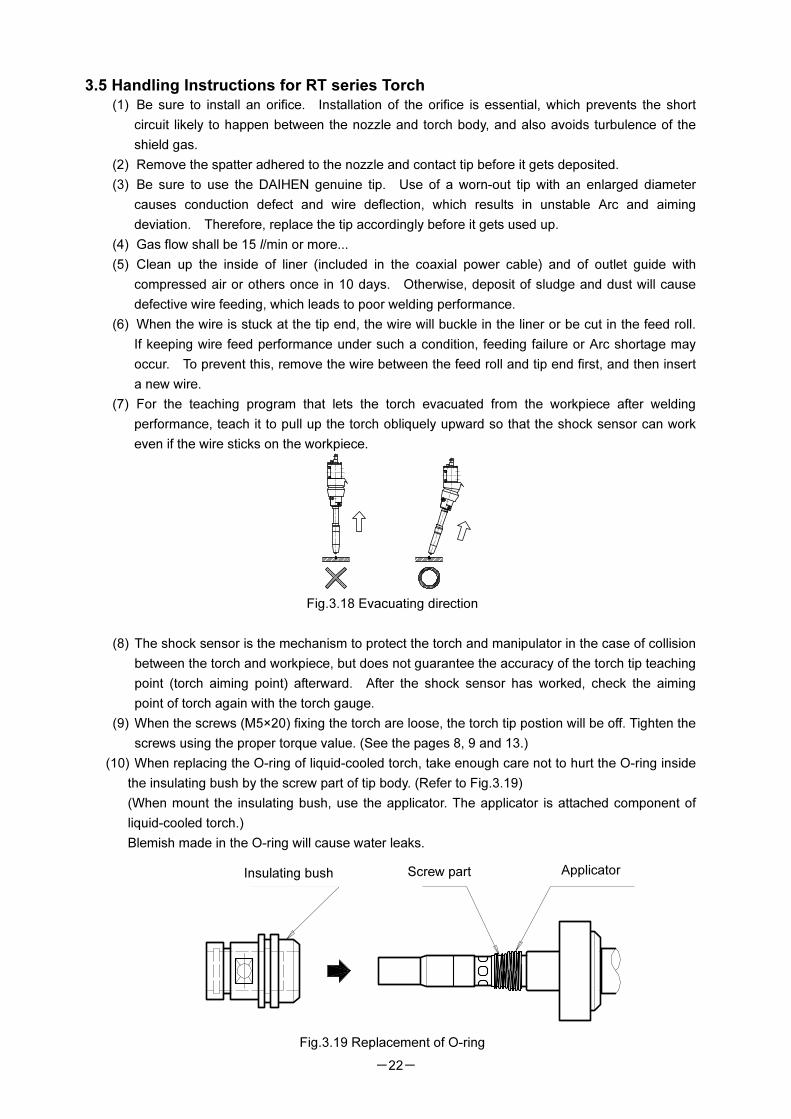
(7) For the teaching program that lets the torch evacuated from the workpiece after welding
performance, teach it to pull up the torch obliquely upward so that the shock sensor can work
even if the wire sticks on the workpiece.
Fig.3.18 Evacuating direction
(8) The shock sensor is the mechanism to protect the torch and manipulator in the case of collision
between the torch and workpiece, but does not guarantee the accuracy of the torch tip teaching
point (torch aiming point) afterward. After the shock sensor has worked, check the aiming
point of torch again with the torch gauge.
(9) When the screws (M5×20) fixing the torch are loose, the torch tip postion will be off. Tighten the
screws using the proper torque value. (See the pages 8, 9 and 13.)
(10) When replacing the O-ring of liquid-cooled torch, take enough care not to hurt the O-ring inside
the insulating bush by the screw part of tip body. (Refer to Fig.3.19)
(When mount the insulating bush, use the applicator. The applicator is attached component of
liquid-cooled torch.)
Blemish made in the O-ring will cause water leaks.
Fig.3.19 Replacement of O-ring
Insulating bush Screw part Applicator
-23-
3.6 Handling Instructions for RZ series Torch (1) Remove spatters that adhered to the nozzle and tip holder before they accumulate there.
(2) For the tip and tip holder, be sure to use the DAIHEN genuine parts.
Using a tip or tip holder with enlarged hole-diameter will cause faulty power supply or swaying
weld wire, thus resulting unstable arcs or a deviation from the aiming point. To avoid that, replace
the tip or tip holder where appropriate.
(3) Provide a gas flow rate at least of 15 liters/minute.
(4) Accumulation of wire chips or dust in the liner (Located in the coaxial power cable), outlet guide,
or stop guide will cause faulty power supply to the weld wire, thus having adverse influence on
welding. To avoid that, clean such parts at regular intervals with compressed air.
(5) If weld wire gets stuck (deposited) at the tip holder end, the weld wire will buckle or be cut in the
feed roll. Continuing to feed the wire under such condition may result in faulty wire feeding or arc
shortage. To avoid that, remove the wire between the feed roll and the tip end, and then lead a
new weld wire.
(6) To lead the weld wire, unfasten the tip holder. Not doing so may cause the wire to buckle. After
the completion of leading the wire, fasten the tip holder.
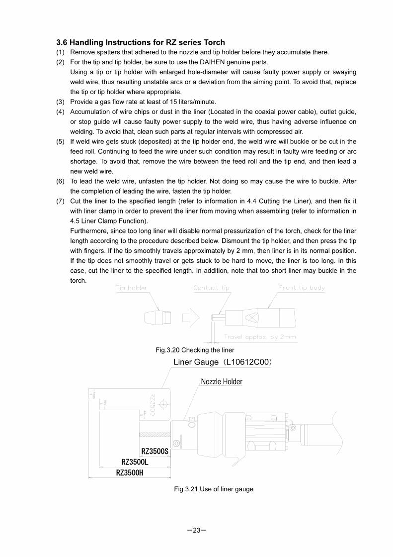
(7) Cut the liner to the specified length (refer to information in 4.4 Cutting the Liner), and then fix it
with liner clamp in order to prevent the liner from moving when assembling (refer to information in
4.5 Liner Clamp Function).
Furthermore, since too long liner will disable normal pressurization of the torch, check for the liner
length according to the procedure described below. Dismount the tip holder, and then press the tip
with fingers. If the tip smoothly travels approximately by 2 mm, then liner is in its normal position.
If the tip does not smoothly travel or gets stuck to be hard to move, the liner is too long. In this
case, cut the liner to the specified length. In addition, note that too short liner may buckle in the
torch.
Fig.3.20 Checking the liner
Fig.3.21 Use of liner gauge
RZ3500H
RZ3500L
RZ3500S
Liner Gauge(L10612C00)
-24-
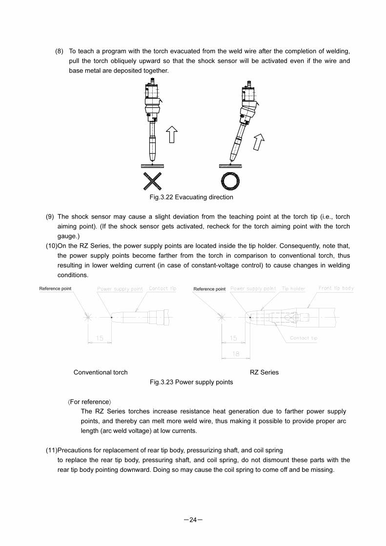
(8) To teach a program with the torch evacuated from the weld wire after the completion of welding,
pull the torch obliquely upward so that the shock sensor will be activated even if the wire and
base metal are deposited together.
Fig.3.22 Evacuating direction
(9) The shock sensor may cause a slight deviation from the teaching point at the torch tip (i.e., torch
aiming point). (If the shock sensor gets activated, recheck for the torch aiming point with the torch
gauge.)
(10) On the RZ Series, the power supply points are located inside the tip holder. Consequently, note that,
the power supply points become farther from the torch in comparison to conventional torch, thus
resulting in lower welding current (in case of constant-voltage control) to cause changes in welding
conditions.
Conventional torch RZ Series
Fig.3.23 Power supply points
⟨For reference⟩
The RZ Series torches increase resistance heat generation due to farther power supply
points, and thereby can melt more weld wire, thus making it possible to provide proper arc
length (arc weld voltage) at low currents.
(11) Precautions for replacement of rear tip body, pressurizing shaft, and coil spring
to replace the rear tip body, pressuring shaft, and coil spring, do not dismount these parts with the
rear tip body pointing downward. Doing so may cause the coil spring to come off and be missing.
-25-
4. Coaxial Power Cable for Robot
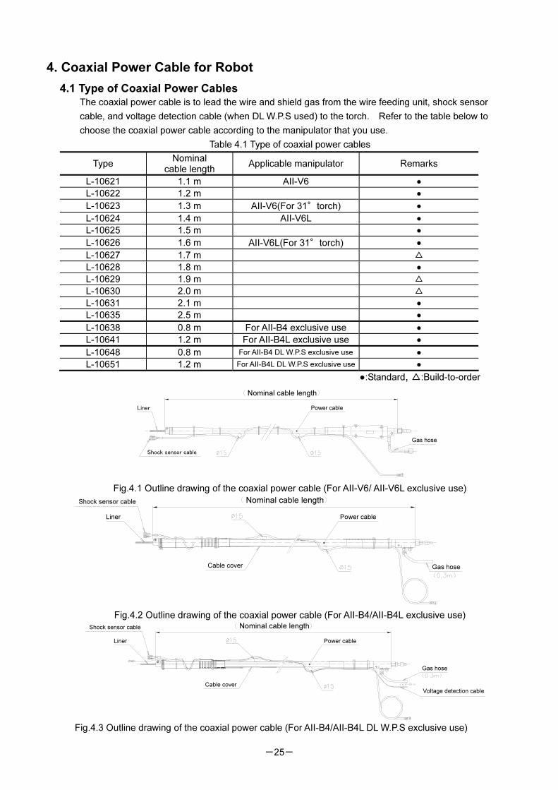
4.1 Type of Coaxial Power Cables The coaxial power cable is to lead the wire and shield gas from the wire feeding unit, shock sensor
cable, and voltage detection cable (when DL W.P.S used) to the torch. Refer to the table below to
choose the coaxial power cable according to the manipulator that you use.
Table 4.1 Type of coaxial power cables
Type Nominal
cable length Applicable manipulator Remarks
L-10621 1.1 m AII-V6 ●
L-10622 1.2 m ●
L-10623 1.3 m AII-V6(For 31°torch) ●
L-10624 1.4 m AII-V6L ●
L-10625 1.5 m ●
L-10626 1.6 m AII-V6L(For 31°torch) ●
L-10627 1.7 m △
L-10628 1.8 m ●
L-10629 1.9 m △
L-10630 2.0 m △
L-10631 2.1 m ●
L-10635 2.5 m ●
L-10638 0.8 m For AII-B4 exclusive use ●
L-10641 1.2 m For AII-B4L exclusive use ●
L-10648 0.8 m For AII-B4 DL W.P.S exclusive use ●
L-10651 1.2 m For AII-B4L DL W.P.S exclusive use ●
●:Standard, △:Build-to-order
Fig.4.1 Outline drawing of the coaxial power cable (For AII-V6/ AII-V6L exclusive use)
Fig.4.2 Outline drawing of the coaxial power cable (For AII-B4/AII-B4L exclusive use)
Fig.4.3 Outline drawing of the coaxial power cable (For AII-B4/AII-B4L DL W.P.S exclusive use)
Nominal cable length
Shock sensor cable
Liner Power cable
Gas hose
Cable cover
Nominal cable length
Power cable
Gas hose
Liner
Shock sensor cable
Gas hose
Voltage detection cable
Liner
Shock sensor cable
Cable cover
Nominal cable length
Power cable
-26-
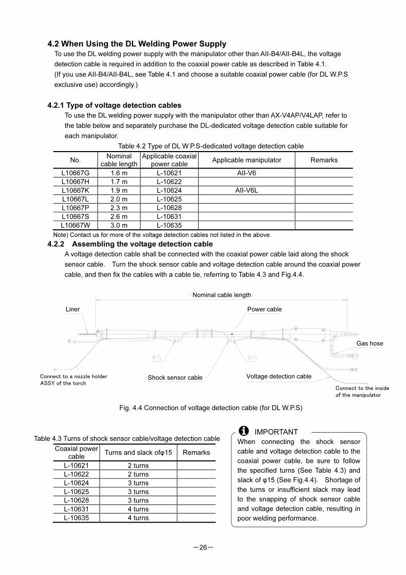
4.2 When Using the DL Welding Power Supply
To use the DL welding power supply with the manipulator other than AII-B4/AII-B4L, the voltage
detection cable is required in addition to the coaxial power cable as described in Table 4.1.
(If you use AII-B4/AII-B4L, see Table 4.1 and choose a suitable coaxial power cable (for DL W.P.S
exclusive use) accordingly.)
4.2.1 Type of voltage detection cables
To use the DL welding power supply with the manipulator other than AX-V4AP/V4LAP, refer to
the table below and separately purchase the DL-dedicated voltage detection cable suitable for
each manipulator.
Table 4.2 Type of DL W.P.S-dedicated voltage detection cable
No. Nominal
cable length Applicable coaxial
power cable Applicable manipulator Remarks
L10667G 1.6 m L-10621 AII-V6
L10667H 1.7 m L-10622
L10667K 1.9 m L-10624 AII-V6L
L10667L 2.0 m L-10625
L10667P 2.3 m L-10628
L10667S 2.6 m L-10631
L10667W 3.0 m L-10635
Note) Contact us for more of the voltage detection cables not listed in the above.
4.2.2 Assembling the voltage detection cable
A voltage detection cable shall be connected with the coaxial power cable laid along the shock
sensor cable. Turn the shock sensor cable and voltage detection cable around the coaxial power
cable, and then fix the cables with a cable tie, referring to Table 4.3 and Fig.4.4.
Fig. 4.4 Connection of voltage detection cable (for DL W.P.S)
Table 4.3 Turns of shock sensor cable/voltage detection cable
Coaxial power cable
Turns and slack ofφ15 Remarks
L-10621 2 turns
L-10622 2 turns
L-10624 3 turns
L-10625 3 turns
L-10628 3 turns
L-10631 4 turns
L-10635 4 turns
When connecting the shock sensor
cable and voltage detection cable to the
coaxial power cable, be sure to follow
the specified turns (See Table 4.3) and
slack of φ15 (See Fig.4.4). Shortage of
the turns or insufficient slack may lead
to the snapping of shock sensor cable
and voltage detection cable, resulting in
poor welding performance.
IMPORTANT
Nominal cable length
Liner Power cable
Gas hose
Shock sensor cable Voltage detection cableConnect to a nozzle holder
ASSY of the torchConnect to the inside
of the manipulator
-27-
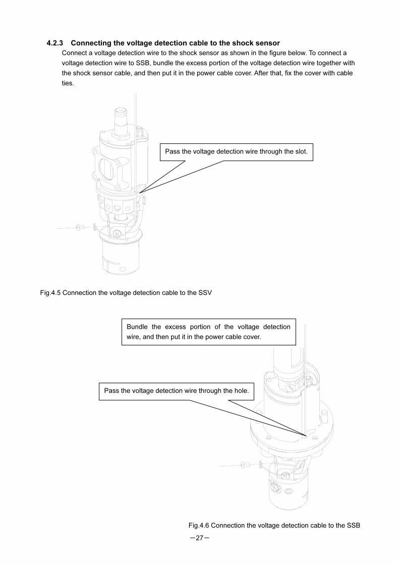
4.2.3 Connecting the voltage detection cable to the shock sensor
Connect a voltage detection wire to the shock sensor as shown in the figure below. To connect a
voltage detection wire to SSB, bundle the excess portion of the voltage detection wire together with
the shock sensor cable, and then put it in the power cable cover. After that, fix the cover with cable
ties.
Pass the voltage detection wire through the slot.
Pass the voltage detection wire through the hole.
Fig.4.5 Connection the voltage detection cable to the SSV
Fig.4.6 Connection the voltage detection cable to the SSB
Bundle the excess portion of the voltage detection
wire, and then put it in the power cable cover.
-28-
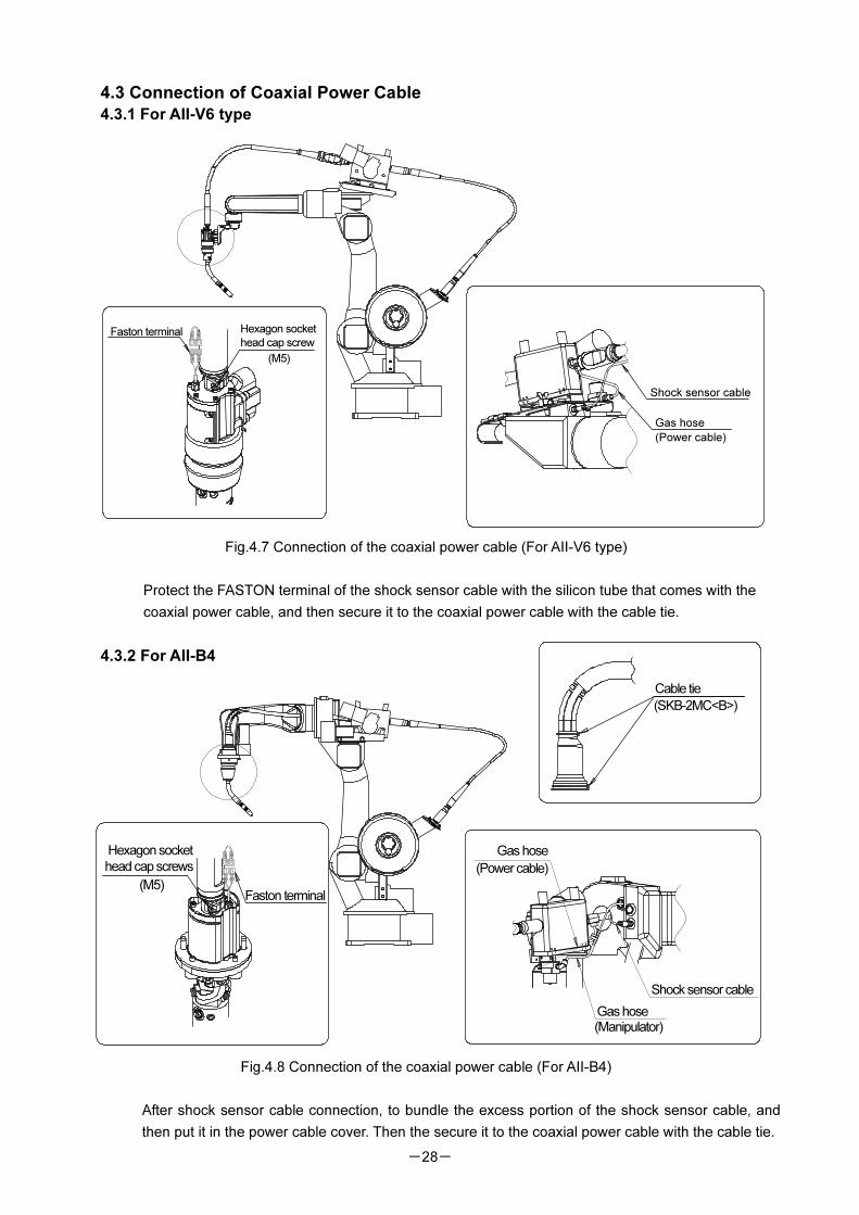
4.3 Connection of Coaxial Power Cable
4.3.1 For AII-V6 type
Fig.4.7 Connection of the coaxial power cable (For AII-V6 type)
Protect the FASTON terminal of the shock sensor cable with the silicon tube that comes with the
coaxial power cable, and then secure it to the coaxial power cable with the cable tie.
4.3.2 For AII-B4
Fig.4.8 Connection of the coaxial power cable (For AII-B4)
After shock sensor cable connection, to bundle the excess portion of the shock sensor cable, and
then put it in the power cable cover. Then the secure it to the coaxial power cable with the cable tie.
(M5)
(Power cable)
Shock sensor cable
Gas hose
Hexagon socket
head cap screwFaston terminal
Hexagon socket
head cap screws
(M5)Faston terminal
Gas hose
Shock sensor cable
(Manipulator)Gas hose
(Power cable)
(SKB-2MC<B>)
Cable tie
-29-
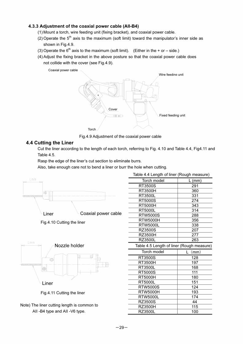
4.3.3 Adjustment of the coaxial power cable (AII-B4)
(1) Mount a torch, wire feeding unit (fixing bracket), and coaxial power cable.
(2) Operate the 5th axis to the maximum (soft limit) toward the manipulator’s inner side as
shown in Fig.4.9.
(3) Operate the 6th axis to the maximum (soft limit). (Either in the + or – side.)
(4) Adjust the fixing bracket in the above posture so that the coaxial power cable does
not collide with the cover (see Fig.4.9).
Fig.4.9 Adjustment of the coaxial power cable
4.4 Cutting the Liner Cut the liner according to the length of each torch, referring to Fig. 4.10 and Table 4.4, Fig4.11 and
Table 4.5.
Rasp the edge of the liner’s cut section to eliminate burrs.
Also, take enough care not to bend a liner or burr the hole when cutting.
Fig.4.10 Cutting the liner
Fig.4.11 Cutting the liner
Note) The liner cutting length is common to
AII -B4 type and AII -V6 type.
Table 4.4 Length of liner (Rough measure)
Torch model L (mm)
RT3500S 291
RT3500H 360
RT3500L 331
RT5000S 274
RT5000H 343
RT5000L 314
RTW5000S 288
RTW5000H 356
RTW5000L 338
RZ3500S 207
RZ3500H 277
RZ3500L 263
一線式パワーケーブル
カバー
トーチ
固定ブラケット
ワイヤ送給装置Coaxial power cable
Wire feeding unit
Cover
Torch
Fixed feeding unit
Table 4.5 Length of liner (Rough measure)
Torch model L(mm)
RT3500S 128
RT3500H 197
RT3500L 168
RT5000S 111
RT5000H 180
RT5000L 151
RTW5000S 124
RTW5000H 193
RTW5000L 174
RZ3500S 44
RZ3500H 115
RZ3500L 100
Coaxial power cableLiner
Liner
Nozzle holder
-30-
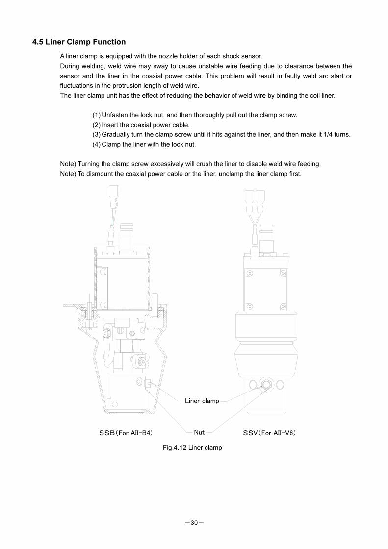
4.5 Liner Clamp Function
A liner clamp is equipped with the nozzle holder of each shock sensor.
During welding, weld wire may sway to cause unstable wire feeding due to clearance between the
sensor and the liner in the coaxial power cable. This problem will result in faulty weld arc start or
fluctuations in the protrusion length of weld wire.
The liner clamp unit has the effect of reducing the behavior of weld wire by binding the coil liner.
(1) Unfasten the lock nut, and then thoroughly pull out the clamp screw.
(2) Insert the coaxial power cable.
(3) Gradually turn the clamp screw until it hits against the liner, and then make it 1/4 turns.
(4) Clamp the liner with the lock nut.
Note) Turning the clamp screw excessively will crush the liner to disable weld wire feeding.
Note) To dismount the coaxial power cable or the liner, unclamp the liner clamp first.
Fig.4.12 Liner clamp
Nut
Liner clamp
SSB(For AII-B4) SSV(For AII-V6)
-31-
5. Setting the Robot Controller
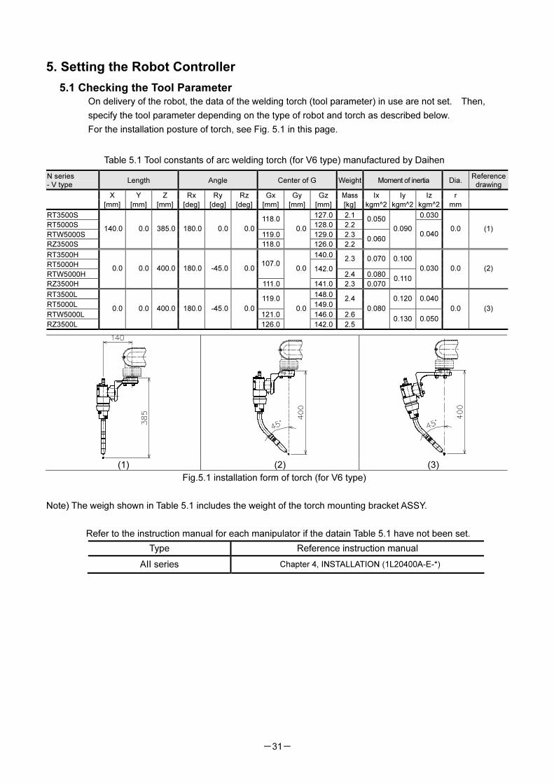
5.1 Checking the Tool Parameter On delivery of the robot, the data of the welding torch (tool parameter) in use are not set. Then,
specify the tool parameter depending on the type of robot and torch as described below.
For the installation posture of torch, see Fig. 5.1 in this page.
Table 5.1 Tool constants of arc welding torch (for V6 type) manufactured by Daihen
N series - V type
Length Angle Center of G Weight Moment of inertia Dia.Reference
drawing
X Y Z Rx Ry Rz Gx Gy Gz Mass Ix Iy Iz r
[mm] [mm] [mm] [deg] [deg] [deg] [mm] [mm] [mm] [kg] kgm^2 kgm^2 kgm^2 mm
RT3500S 127.0 2.1 0.030
RT5000S 118.0
128.0 2.20.050
RTW5000S 119.0 129.0 2.3
RZ3500S
140.0 0.0 385.0 180.0 0.0 0.0
118.0
0.0
126.0 2.20.060
0.090 0.040
0.0 (1)
RT3500H 140.0
RT5000H 2.3 0.070 0.100
RTW5000H
107.0142.0
2.4 0.080
RZ3500H
0.0 0.0 400.0 180.0 -45.0 0.0
111.0
0.0
141.0 2.3 0.0700.110
0.030 0.0 (2)
RT3500L 148.0
RT5000L 119.0
149.02.4 0.120 0.040
RTW5000L 121.0 146.0 2.6
RZ3500L
0.0 0.0 400.0 180.0 -45.0 0.0
126.0
0.0
142.0 2.5
0.080
0.130 0.050
0.0 (3)
(1) (2) (3)
Fig.5.1 installation form of torch (for V6 type)
Note) The weigh shown in Table 5.1 includes the weight of the torch mounting bracket ASSY.
Refer to the instruction manual for each manipulator if the datain Table 5.1 have not been set.
Type Reference instruction manual
AII series Chapter 4, INSTALLATION (1L20400A-E-*)
-32-
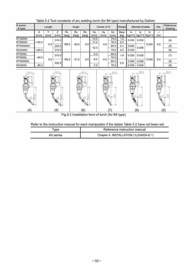
Table 5.2 Tool constants of arc welding torch (for B4 type) manufactured by Daihen
N series - B type
Length Angle Center of G Weight Moment of inertia Dia.Reference
drawing
X Y Z Rx Ry Rz Gx Gy Gz Mass Ix Iy Iz r
[mm] [mm] [mm] [deg] [deg] [deg] [mm] [mm] [mm] [kg] kgm^2 kgm^2 Kgm^2 mm
RT3500H -10.0 74.0 1.9
RT5000H 310.0
-11.0 76.0 2.00.030 0.030 (4)
RTW5000H
-135.5
320.0 85.0 2.1 0.040 (5)
RZ3500H -140.5
0.0
315.0
180.0 -45.0 0.0
-12.0
0.0
79.0 2.0 0.0300.040
0.000 0.0
(6)
RT3500L -5.0 69.0
RT5000L 310.0
70.01.9 0.030 0.030 (7)
RTW5000L
-90.5 -6.0
82.0 0.040 0.040 (8)
RZ3500L -95.5
0.0
330.0
180.0 -31.0 0.0
-7.0
0.0
78.02.0
0.030 0.030
0.000 0.0
(9)
(4) (5) (6) (7) (8) (9)
Fig.5.2 Installation form of torch (for B4 type)
Refer to the instruction manual for each manipulator if the datain Table 5.2 have not been set.
Type Reference instruction manual
AII series Chapter 4, INSTALLATION (1L20400A-E-*)
-33-
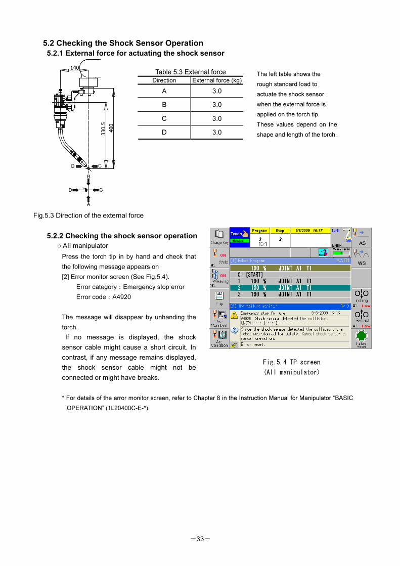
5.2 Checking the Shock Sensor Operation
5.2.1 External force for actuating the shock sensor
Table 5.3 External force
Direction External force (kg)
A 3.0
B 3.0
C 3.0
D 3.0
The left table shows the
rough standard load to
actuate the shock sensor
when the external force is
applied on the torch tip.
These values depend on the
shape and length of the torch.
Fig.5.3 Direction of the external force
5.2.2 Checking the shock sensor operation
○ AII manipulator
Press the torch tip in by hand and check that
the following message appears on
[2] Error monitor screen (See Fig.5.4).
Error category:Emergency stop error
Error code:A4920
The message will disappear by unhanding the
torch.
If no message is displayed, the shock
sensor cable might cause a short circuit. In
contrast, if any message remains displayed,
the shock sensor cable might not be
connected or might have breaks.
* For details of the error monitor screen, refer to Chapter 8 in the Instruction Manual for Manipulator “BASIC
OPERATION” (1L20400C-E-*).
Fig.5.4 TP screen
(AII manipulator)
400
140
330.5
D
A
B
CD
C
-34-
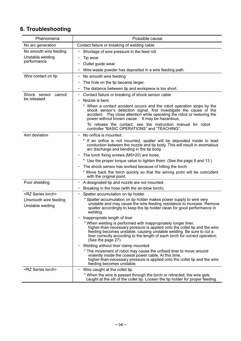
6. Troubleshooting
Phenomena Possible cause
No arc generation Contact failure or breaking of welding cable
No smooth wire feeding
Unstable welding performance
・ Shortage of wire pressure in the feed roll
・ Tip wear
・ Outlet guide wear
・ Wire waste powder has deposited in a wire feeding path.
Wire contact on tip ・ No smooth wire feeding
・ The hole on the tip became larger.
・ The distance between tip and workpiece is too short.
Shock sensor cannot be released.
・ Contact failure or breaking of shock sensor cable
・ Nozzle is bent.
* When a contact accident occurs and the robot operation stops by the shock sensor’s detection signal, first investigate the cause of the accident. Pay close attention while operating the robot or restoring the power without known cause. It may be hazardous.
To release the contact, see the instruction manual for robot controller “BASIC OPERATIONS” and “TEACHING”.
Aim deviation ・ No orifice is mounted.
* If an orifice is not mounted, spatter will be deposited inside to lead conduction between the nozzle and tip body. This will result in anomalous arc discharge and bending in the tip body.
・ The torch fixing screws (M5×20) are loose,
* Use the proper torque value to tighten them. (See the page 9 and 13.)
・ The shock sensor has worked because of hitting the torch.
* Move back the torch quickly so that the aiming point will be coincident with the original point.
Poor shielding ・ A designated tip and nozzle are not mounted.
・ Breaking in the hose (with the air-blow torch).
<RZ Series torch>
Unsmooth wire feeding
Unstable welding
・ Spatter accumulation on tip holder
* Spatter accumulation on tip holder makes power supply to wire very unstable and may cause the wire feeding resistance to increase. Remove spatter accordingly to keep the tip holder clean for good performance in welding.
・ Inappropriate length of liner
* When welding is performed with inappropriately longer liner, higher-than-necessary pressure is applied onto the collet tip and the wire feeding becomes unstable, causing unstable welding. Be sure to cut a liner correctly according to the length of each torch for correct operation. (See the page 27).
・ Welding without liner clamp mounted
* The movement of robot may cause the unfixed liner to move around violently inside the coaxial power cable. At this time, higher-than-necessary pressure is applied onto the collet tip and the wire feeding becomes unstable.
<RZ Series torch> ・ Wire caught at the collet tip.
* When the wire is passed through the torch or retracted, the wire gets caught at the slit of the collet tip. Loosen the tip holder for proper feeding.
-35-
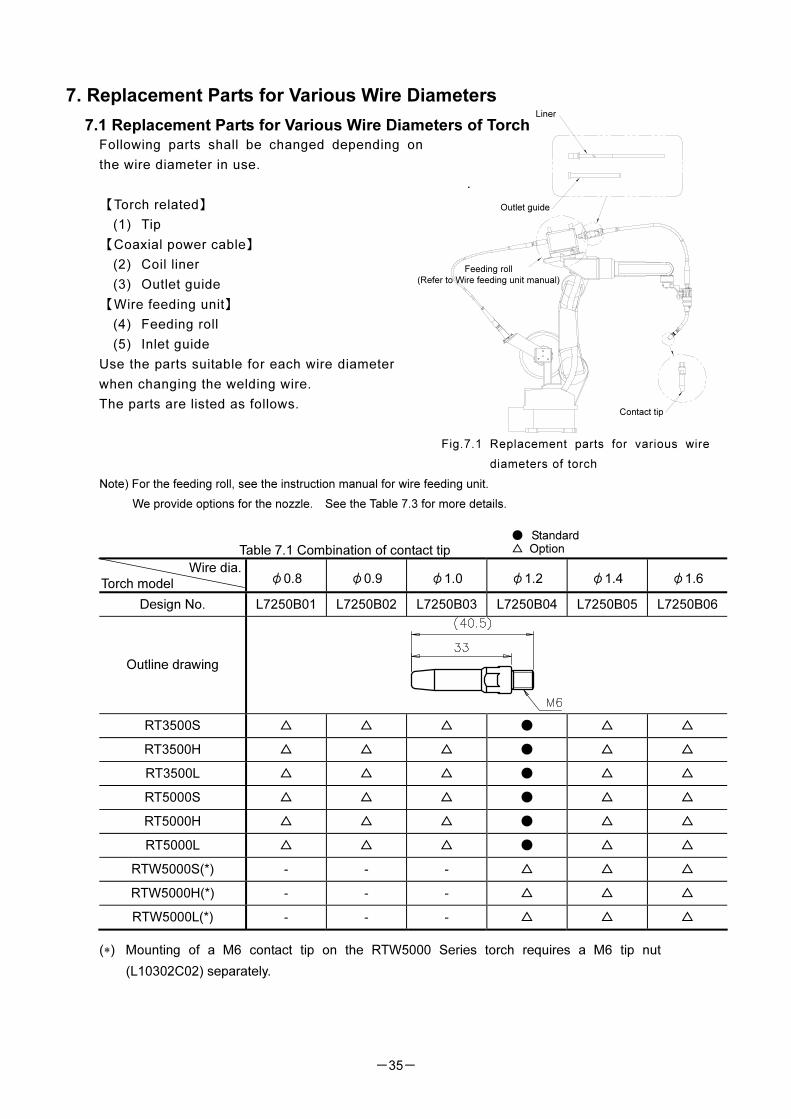
7. Replacement Parts for Various Wire Diameters
7.1 Replacement Parts for Various Wire Diameters of Torch Following parts shall be changed depending on
the wire diameter in use.
【Torch related】
(1) Tip
【Coaxial power cable】
(2) Coil liner
(3) Outlet guide
【Wire feeding unit】
(4) Feeding roll
(5) Inlet guide
Use the parts suitable for each wire diameter
when changing the welding wire.
The parts are listed as follows.
Fig.7.1 Replacement parts for various wire
diameters of torch
Note) For the feeding roll, see the instruction manual for wire feeding unit.
We provide options for the nozzle. See the Table 7.3 for more details.
Table 7.1 Combination of contact tip
Wire dia.
Torch model φ0.8 φ0.9 φ1.0 φ1.2 φ1.4 φ1.6
Design No. L7250B01 L7250B02 L7250B03 L7250B04 L7250B05 L7250B06
Outline drawing
RT3500S △ △ △ ● △ △
RT3500H △ △ △ ● △ △
RT3500L △ △ △ ● △ △
RT5000S △ △ △ ● △ △
RT5000H △ △ △ ● △ △
RT5000L △ △ △ ● △ △
RTW5000S(*) ‐ ‐ ‐ △ △ △
RTW5000H(*) ‐ ‐ ‐ △ △ △
RTW5000L(*) ‐ ‐ ‐ △ △ △
(∗) Mounting of a M6 contact tip on the RTW5000 Series torch requires a M6 tip nut
(L10302C02) separately.
● Standard △ Option
Outlet guide
Liner
Feeding roll
(Refer to Wire feeding unit manual)
Contact tip
-36-
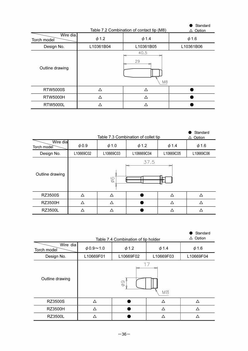
Table 7.2 Combination of contact tip (M8)
Wire dia.Torch model φ1.2 φ1.4 φ1.6
Design No. L10361B04 L10361B05 L10361B06
Outline drawing
RTW5000S △ △ ●
RTW5000H △ △ ●
RTW5000L △ △ ●
Table 7.3 Combination of collet tip
Wire diaTorch model φ0.9 φ1.0 φ1.2 φ1.4 φ1.6
Design No. L10669C02 L10669C03 L106669C04 L10669C05 L10669C06
Outline drawing
RZ3500S △ △ ● △ △
RZ3500H △ △ ● △ △
RZ3500L △ △ ● △ △
Table 7.4 Combination of tip holder
Wire dia
Torch model φ0.9~1.0 φ1.2 φ1.4 φ1.6
Design No. L10669F01 L10669F02 L10669F03 L10669F04
Outline drawing
RZ3500S △ ● △ △
RZ3500H △ ● △ △
RZ3500L △ ● △ △
● Standard
△ Option
● Standard
△ Option
● Standard
△ Option
-37-
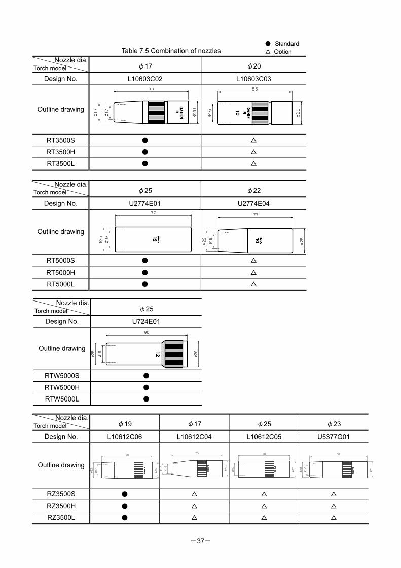
Table 7.5 Combination of nozzles
Nozzle dia. Torch model φ17 φ20
Design No. L10603C02 L10603C03
Outline drawing
RT3500S ● △
RT3500H ● △
RT3500L ● △
Nozzle dia. Torch model φ25
Design No. U724E01
Outline drawing
RTW5000S ●
RTW5000H ●
RTW5000L ●
Nozzle dia. Torch model φ19 φ17 φ25 φ23
Design No. L10612C06 L10612C04 L10612C05 U5377G01
Outline drawing
RZ3500S ● △ △ △
RZ3500H ● △ △ △
RZ3500L ● △ △ △
Nozzle dia. Torch model φ25 φ22
Design No. U2774E01 U2774E04
Outline drawing
RT5000S ● △
RT5000H ● △
RT5000L ● △
● Standard
△ Option
-38-
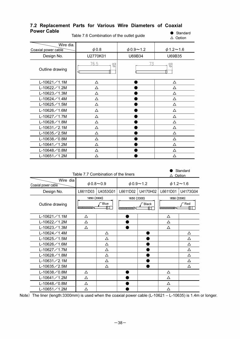
7.2 Replacement Parts for Various Wire Diameters of Coaxial Power Cable
Table 7.6 Combination of the outlet guide
Wire dia.
Coaxial power cable φ0.8 φ0.9~1.2 φ1.2~1.6
Design No. U2770K01 U69B34 U69B35
Outline drawing
L-10621/1.1M △ ● △
L-10622/1.2M △ ● △
L-10623/1.3M △ ● △
L-10624/1.4M △ ● △
L-10625/1.5M △ ● △
L-10626/1.6M △ ● △
L-10627/1.7M △ ● △
L-10628/1.8M △ ● △
L-10631/2.1M △ ● △
L-10635/2.5M △ ● △
L-10638/0.8M △ ● △
L-10641/1.2M △ ● △
L-10648/0.8M △ ● △
L-10651/1.2M △ ● △
Table 7.7 Combination of the liners
Wire dia
Coaxial power cable φ0.8~0.9 φ0.9~1.2 φ1.2~1.6
Design No. L6611D03 U4353G01 L6611D02 U4170H02 L6611D01 U4173G04
Outline drawing
L-10621/1.1M △ ● △
L-10622/1.2M △ ● △
L-10623/1.3M △ ● △
L-10624/1.4M △ ● △
L-10625/1.5M △ ● △
L-10626/1.6M △ ● △
L-10627/1.7M △ ● △
L-10628/1.8M △ ● △
L-10631/2.1M △ ● △
L-10635/2.5M △ ● △
L-10638/0.8M △ ● △
L-10641/1.2M △ ● △
L-10648/0.8M △ ● △
L-10651/1.2M △ ● △
Note)The liner (length:3300mm) is used when the coaxial power cable (L-10621 – L-10635) is 1.4m or longer.
● Standard
△ Option
● Standard
△ Option
Red Blue Black
-39-
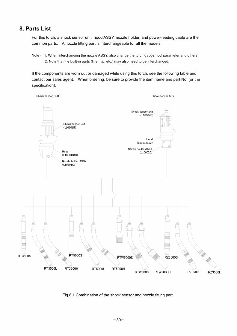
8. Parts List
For this torch, a shock sensor unit, hood ASSY, nozzle holder, and power-feeding cable are the
common parts. A nozzle fitting part is interchangeable for all the models.
Note) 1. When interchanging the nozzle ASSY, also change the torch gauge, tool parameter and others.
2. Note that the built-in parts (liner, tip, etc.) may also need to be interchanged.
If the components are worn out or damaged while using this torch, see the following table and
contact our sales agent. When ordering, be sure to provide the item name and part No. (or the
specification).
Fig.8.1 Combination of the shock sensor and nozzle fitting part
RT3500L RT3500H
RTW5000L RTW5000H
RT5000L
RZ3500L RZ3500H
RT3500S RT5000SRTW5000S RZ3500S
RT5000H
Shock sensor unit
(L10602B)
Hood
(L10602B02)
Nozzle holder ASSY
(L10602C)
Shock sensor unit
(L10601B)
Hood
(L10601B10)
Nozzle holder ASSY
(L10601C)
Shock sensor SSB Shock sensor SSV
-40-
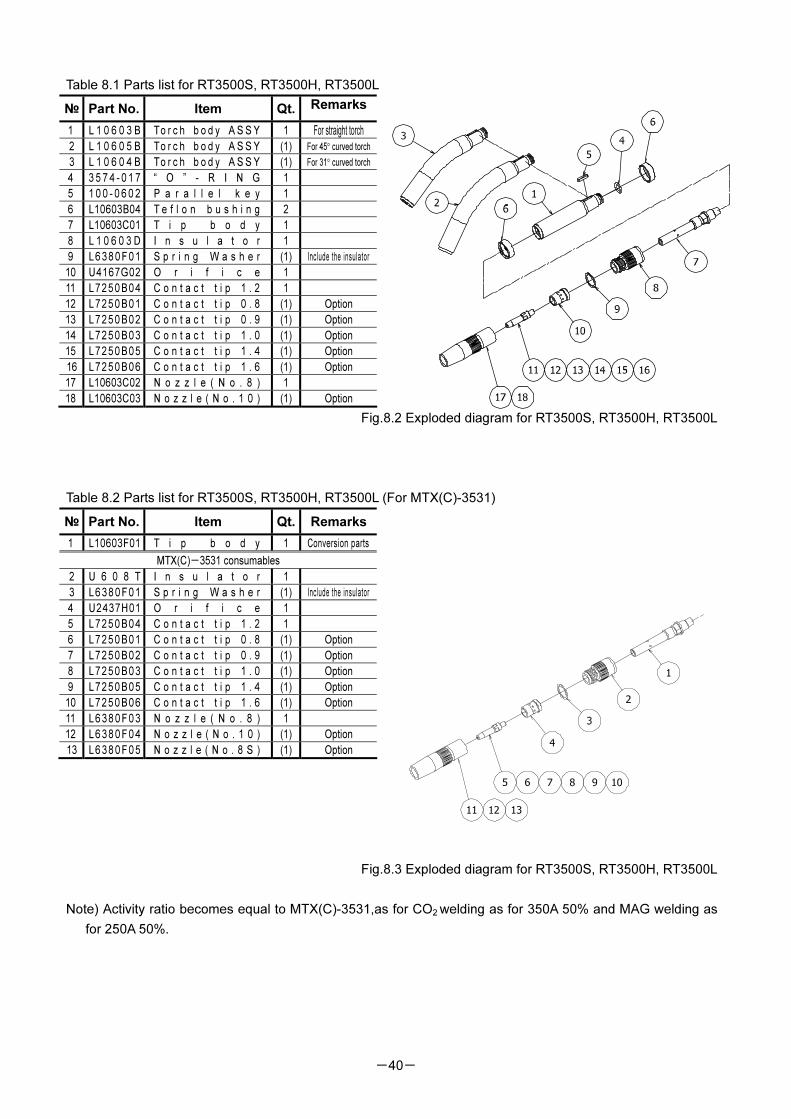
Table 8.1 Parts list for RT3500S, RT3500H, RT3500L
№ Part No. Item Qt. Remarks
1 L 1 0 6 0 3 B To r c h b o d y A S S Y 1 For straight torch
2 L 1 0 6 0 5 B To r c h b o d y A S S Y (1) For 45° curved torch
3 L 1 0 6 0 4 B To r c h b o d y A S S Y (1) For 31° curved torch
4 3 5 7 4 - 0 1 7 “ O ” - R I N G 1
5 1 0 0 - 0 6 0 2 P a r a l l e l k e y 1
6 L10603B04 T e f l o n b u s h i n g 2
7 L10603C01 T i p b o d y 1
8 L 1 0 6 0 3 D I n s u l a t o r 1
9 L6 38 0 F0 1 S p r i n g W a s h e r (1) Include the insulator
10 U4167G02 O r i f i c e 1
11 L7250B04 C o n t a c t t i p 1 . 2 1
12 L7250B01 C o n t a c t t i p 0 . 8 (1) Option
13 L7250B02 C o n t a c t t i p 0 . 9 (1) Option
14 L7250B03 C o n t a c t t i p 1 . 0 (1) Option
15 L7250B05 C o n t a c t t i p 1 . 4 (1) Option
16 L7250B06 C o n t a c t t i p 1 . 6 (1) Option
17 L10603C02 N o z z l e ( N o . 8 ) 1
18 L10603C03 N o z z l e ( N o . 1 0 ) (1) Option
Fig.8.2 Exploded diagram for RT3500S, RT3500H, RT3500L
Table 8.2 Parts list for RT3500S, RT3500H, RT3500L (For MTX(C)-3531)
Fig.8.3 Exploded diagram for RT3500S, RT3500H, RT3500L
Note) Activity ratio becomes equal to MTX(C)-3531,as for CO2 welding as for 350A 50% and MAG welding as
for 250A 50%.
№ Part No. Item Qt. Remarks
1 L10603F01 T i p b o d y 1 Conversion parts
MTX(C)-3531 consumables
2 U 6 0 8 T I n s u l a t o r 1
3 L6 38 0 F0 1 S p r i n g W a s h e r (1) Include the insulator
4 U2437H01 O r i f i c e 1
5 L7250B04 C o n t a c t t i p 1 . 2 1
6 L7250B01 C o n t a c t t i p 0 . 8 (1) Option
7 L7250B02 C o n t a c t t i p 0 . 9 (1) Option
8 L7250B03 C o n t a c t t i p 1 . 0 (1) Option
9 L7250B05 C o n t a c t t i p 1 . 4 (1) Option
10 L7250B06 C o n t a c t t i p 1 . 6 (1) Option
11 L6 38 0 F0 3 N o z z l e ( N o . 8 ) 1
12 L6 38 0 F0 4 N o z z l e ( N o . 1 0 ) (1) Option
13 L6 38 0 F0 5 N o z z l e ( N o . 8 S ) (1) Option
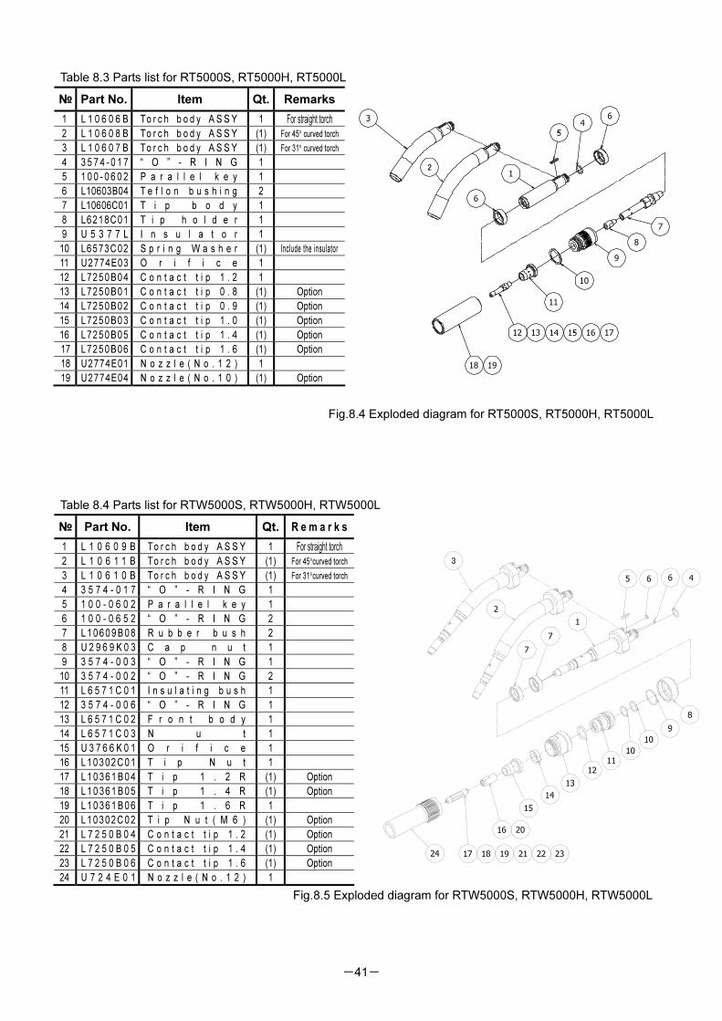
-41-
Table 8.3 Parts list for RT5000S, RT5000H, RT5000L
Fig.8.4 Exploded diagram for RT5000S, RT5000H, RT5000L
Table 8.4 Parts list for RTW5000S, RTW5000H, RTW5000L
Fig.8.5 Exploded diagram for RTW5000S, RTW5000H, RTW5000L
№ Part No. Item Qt. Remarks
1 L 1 0 6 0 6 B To r c h b o d y A S S Y 1 For straight torch
2 L 1 0 6 0 8 B To r c h b o d y A S S Y (1) For 45° curved torch
3 L 1 0 6 0 7 B To r c h b o d y A S S Y (1) For 31° curved torch
4 3 5 7 4 - 0 1 7 “ O ” - R I N G 1
5 1 0 0 - 0 6 0 2 P a r a l l e l k e y 1
6 L10603B04 T e f l o n b u s h i n g 2
7 L10606C01 T i p b o d y 1
8 L6218C01 T i p h o l d e r 1
9 U 5 3 7 7 L I n s u l a t o r 1
10 L6573C02 S p r i n g W a s h e r (1) Include the insulator
11 U2774E03 O r i f i c e 1
12 L7250B04 C o n t a c t t i p 1 . 2 1
13 L7250B01 C o n t a c t t i p 0 . 8 (1) Option
14 L7250B02 C o n t a c t t i p 0 . 9 (1) Option
15 L7250B03 C o n t a c t t i p 1 . 0 (1) Option
16 L7250B05 C o n t a c t t i p 1 . 4 (1) Option
17 L7250B06 C o n t a c t t i p 1 . 6 (1) Option
18 U2774E01 N o z z l e ( N o . 1 2 ) 1
19 U2774E04 N o z z l e ( N o . 1 0 ) (1) Option
№ Part No. Item Qt. R e m a r k s
1 L 1 0 6 0 9 B To r c h b o d y A S S Y 1 For straight torch
2 L 1 0 6 1 1 B To r c h b o d y A S S Y (1) For 45°curved torch
3 L 1 0 6 1 0 B To r c h b o d y A S S Y (1) For 31°curved torch
4 3 5 7 4 - 0 1 7 “ O ” - R I N G 1
5 1 0 0 - 0 6 0 2 P a r a l l e l k e y 1
6 1 0 0 - 0 6 5 2 “ O ” - R I N G 2
7 L 1 0 6 0 9 B 0 8 R u b b e r b u s h 2
8 U 2 9 6 9 K 0 3 C a p n u t 1
9 3 5 7 4 - 0 0 3 “ O ” - R I N G 1
10 3 5 7 4 - 0 0 2 “ O ” - R I N G 2
11 L 6 5 7 1 C 0 1 I n s u l a t i n g b u s h 1
12 3 5 7 4 - 0 0 6 “ O ” - R I N G 1
13 L 6 5 7 1 C 0 2 F r o n t b o d y 1
14 L 6 5 7 1 C 0 3 N u t 1
15 U 3 7 6 6 K 0 1 O r i f i c e 1
16 L 1 0 3 0 2 C 0 1 T i p N u t 1
17 L 1 0 3 6 1 B 0 4 T i p 1 . 2 R (1) Option
18 L 1 0 3 6 1 B 0 5 T i p 1 . 4 R (1) Option
19 L 1 0 3 6 1 B 0 6 T i p 1 . 6 R 1
20 L 1 0 3 0 2 C 0 2 T i p N u t ( M 6 ) (1) Option
21 L 7 2 5 0 B 0 4 C o n t a c t t i p 1 . 2 (1) Option
22 L 7 2 5 0 B 0 5 C o n t a c t t i p 1 . 4 (1) Option
23 L 7 2 5 0 B 0 6 C o n t a c t t i p 1 . 6 (1) Option
24 U 7 2 4 E 0 1 N o z z l e ( N o . 1 2 ) 1
8
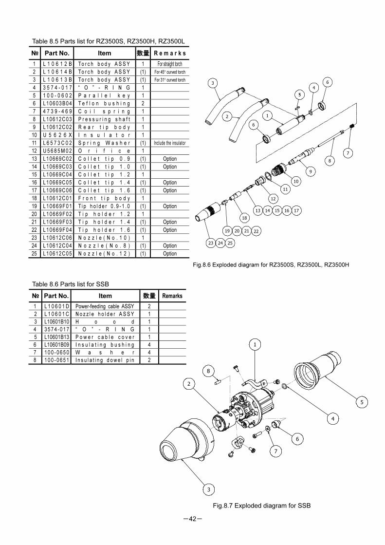
-42-
Table 8.5 Parts list for RZ3500S, RZ3500H, RZ3500L
22
Fig.8.6 Exploded diagram for RZ3500S, RZ3500L, RZ3500H
Table 8.6 Parts list for SSB
№ Part No. Item 数量 Remarks
1 L 1 0 6 0 1 D Power-feeding cable ASSY 2
2 L 1 0 6 0 1 C N o z z l e h o l d e r A S S Y 1
3 L10601B10 H o o d 1
4 3 5 7 4 - 0 1 7 “ O ” - R I N G 1
5 L10601B13 P o w e r c a b l e c o v e r 1
6 L10601B09 I n s u l a t i n g b u s h i n g 4
7 1 0 0 - 0 6 5 0 W a s h e r 4
8 1 0 0 - 0 6 5 1 I n s u l a t i n g d o w e l p i n 2
Fig.8.7 Exploded diagram for SSB
№ Part No. Item 数量 R e m a r k s
1 L 1 0 6 1 2 B To r c h b o d y A S S Y 1 For straight torch
2 L 1 0 6 1 4 B To r c h b o d y A S S Y (1) For 45° curved torch
3 L 1 0 6 1 3 B To r c h b o d y A S S Y (1) For 31° curved torch
4 3 5 7 4 - 0 1 7 “ O ” - R I N G 1
5 1 0 0 - 0 6 0 2 P a r a l l e l k e y 1
6 L1 0 6 03 B 0 4 T e f l o n b u s h i n g 2
7 4 7 3 9 - 4 6 9 C o i l s p r i n g 1
8 L10612C03 P r e s s u r i n g s h a f t 1
9 L10612C02 R e a r t i p b o d y 1
10 U 5 6 2 6 X I n s u l a t o r 1
11 L 6 5 7 3 C 0 2 S p r i n g W a s h e r (1) Include the insulator
12 U 5 6 8 5 M 0 2 O r i f i c e 1
13 L10669C02 C o l l e t t i p 0 . 9 (1) Option
14 L10669C03 C o l l e t t i p 1 . 0 (1) Option
15 L10669C04 C o l l e t t i p 1 . 2 1
16 L10669C05 C o l l e t t i p 1 . 4 (1) Option
17 L10669C06 C o l l e t t i p 1 . 6 (1) Option
18 L10612C01 F r o n t t i p b o d y 1
19 L 1 0 6 6 9 F 0 1 T i p h o l d e r 0 . 9 - 1 . 0 (1) Option
20 L 1 0 6 6 9 F 0 2 T i p h o l d e r 1 . 2 1
21 L 1 0 6 6 9 F 0 3 T i p h o l d e r 1 . 4 (1) Option
22 L 1 0 6 6 9 F 0 4 T i p h o l d e r 1 . 6 (1) Option
23 L10612C06 N o z z l e ( N o . 1 0 ) 1
24 L10612C04 N o z z l e ( N o . 8 ) (1) Option
25 L10612C05 N o z z l e ( N o . 1 2 ) (1) Option
8
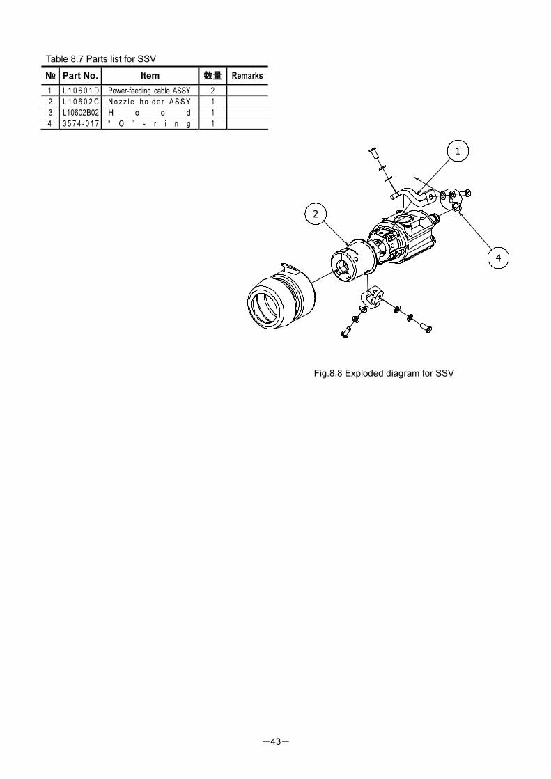
-43-
Table 8.7 Parts list for SSV
№ Part No. Item 数量 Remarks
1 L 1 0 6 0 1 D Power-feeding cable ASSY 2
2 L 1 0 6 0 2 C N o z z l e h o l d e r A S S Y 1
3 L10602B02 H o o d 1
4 3 5 7 4 - 0 1 7 “ O ” - r i n g 1
Fig.8.8 Exploded diagram for SSV
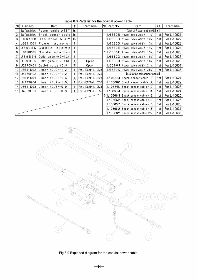
-44-
Table 8.8 Parts list for the coaxial power cable
№ Part No. Item Qt. Remarks № Part No. Item Qt. Remarks
1 See Table. below. P o w e r c a b l e A S S Y 1st 【List of Power cable ASSY】
2 See Table. below. S h o c k s e n s o r c a b l e 1st L 6 5 8 0 B Power cable ASSY(1.1M) 1st For L-10621
3 L 6 6 1 1 B G a s h o s e A S S Y 1st L 6 5 8 0 C Power cable ASSY(1.2M) 1st For L-10622
4 L6611C01 P o w e r a d a p t o r 1 L 6 5 8 0 D Power cable ASSY(1.3M) 1st For L-10623
5 U 5 0 3 5 K C a b l e c l a m p 1 L 6 5 8 0 E Power cable ASSY(1.4M) 1st For L-10624
6 L7810D05 G u i d e a d a p t o r 1 L 6 5 8 0 F Power cable ASSY(1.5M) 1st For L-10625
7 U 6 9 B 3 4 Outlet guide(0.9~1.2) 1 L658 0G Power cable ASSY(1.6M) 1st For L-10626
8 U 6 9 B 3 5 Outlet guide(1.2~1.6) (1) Option L 6 5 8 0 H Power cable ASSY(1.8M) 1st For L-10628
9 U2770K01 O u t l e t g u i d e ( 0 . 8 ) (1) Option L 6 5 8 0 J Power cable ASSY(2.1M) 1st For L-10631
10 L6611D02 L i n e r (0 . 9 ~1 . 2 ) 1 For L-10621~L-10623
1
L 6 5 8 0 K Power cable ASSY(2.5M) 1st For L-10635
11 U4170H02 L i n e r (0 . 9 ~1 . 2 ) 1 For L-10624~L-10635 【List of Shock sensor cable】
12 L6611D01 L i n e r (1 . 2 ~1 . 6 ) (1) For L-10621~L-10623 L10666J S h o c k s e n s o r c a b l e(8) 1st For L-10621
13 U4173G04 L i n e r (1 . 2 ~1 . 6 ) (1) For L-10624~L-10635 L10666K S h o c k s e n s o r c a b l e(9) 1st For L-10622
14 L6611D03 L i n e r (0 . 8 ~0 . 9 ) (1) For L-10621~L-10623 L10666L Shock sensor cab le(10) 1st For L-10623
15 U4353G01 L i n e r (0 . 8 ~0 . 9 ) (1) For L-10624~L-10635 L10666M Shock sensor cab le(11) 1st For L-10624
L10666N Shock sensor cab le(12) 1st For L-10625
L10666P Shock sensor cab le(13) 1st For L-10626
L10666R Shock sensor cab le(15) 1st For L-10628
L10666U Shock sensor cab le(18) 1st For L-10631
2
L10666Y Shock sensor cab le(22) 1st For L-10635
Fig.8.9 Exploded diagram for the coaxial power cable
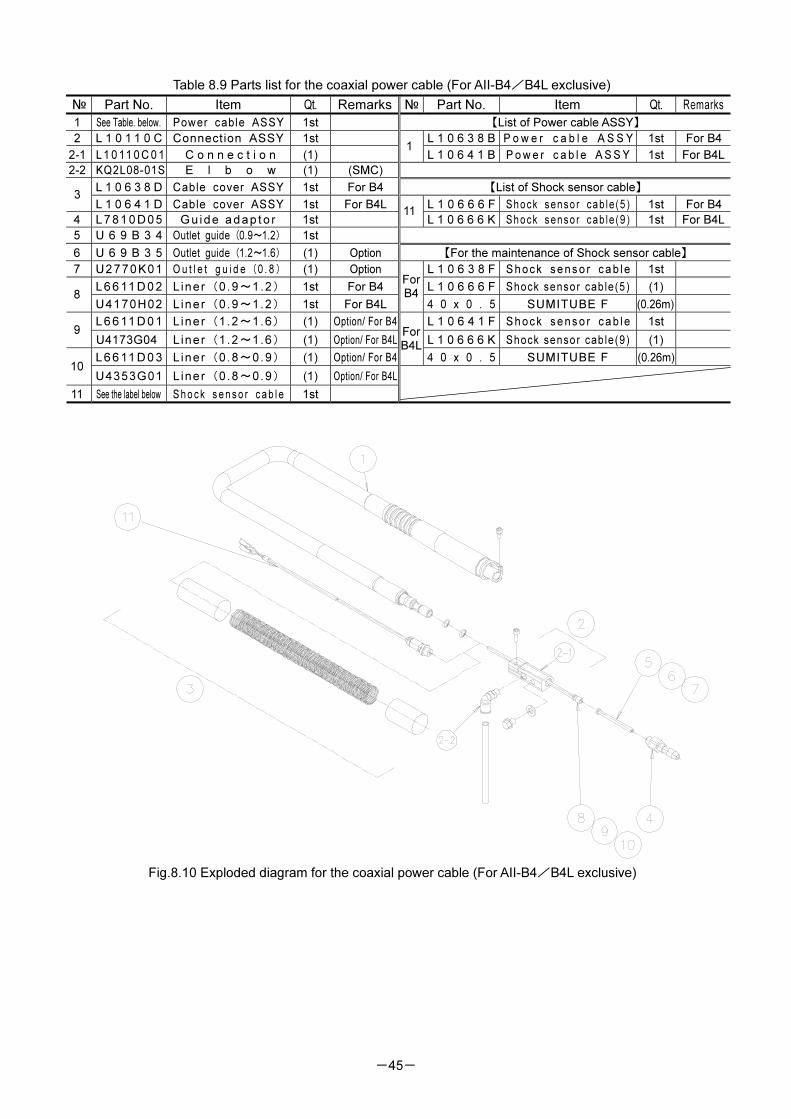
-45-
Table 8.9 Parts list for the coaxial power cable (For AII-B4/B4L exclusive)
№ Part No. Item Qt. Remarks № Part No. Item Qt. Remarks
1 See Table. below. Power cable ASSY 1st 【List of Power cable ASSY】
2 L 1 0 1 1 0 C Connection ASSY 1st L 1 0 6 3 8 B P o w e r c a b l e A S S Y 1st For B4
2-1 L 1 0 11 0 C 0 1 C o n n e c t i o n (1) 1
L 1 0 6 4 1 B P o w e r c a b l e A S S Y 1st For B4L
2-2 KQ2L08-01S E l b o w (1) (SMC)
L 1 0 6 3 8 D Cable cover ASSY 1st For B4 【List of Shock sensor cable】 3
L 1 0 6 4 1 D Cable cover ASSY 1st For B4L L 1 0 6 6 6 F Shock senso r cab le (5 ) 1st For B4
4 L 7 8 1 0 D 0 5 Gu ide a dap to r 1st 11
L 1 0 6 6 6 K Shock senso r cab le (9 ) 1st For B4L
5 U 6 9 B 3 4 Outlet guide(0.9~1.2) 1st
6 U 6 9 B 3 5 Outlet guide(1.2~1.6) (1) Option 【For the maintenance of Shock sensor cable】
7 U2770K01 O u t l e t g u i d e(0 . 8) (1) Option L 1 0 6 3 8 F S h o c k s e n s o r c a b l e 1st
L 6 6 11 D 0 2 L iner(0.9~1.2) 1st For B4 L 1 0 6 6 6 F Shock sensor cable(5) (1) 8
U4170H02 L iner(0.9~1.2) 1st For B4L
For B4
4 0 x 0 . 5 SUMITUBE F (0.26m)
L 6 6 11 D 0 1 L iner(1.2~1.6) (1) Option/ For B4 L 1 0 6 4 1 F S h o c k s e n s o r c a b l e 1st 9
U4173G04 Liner(1.2~1.6) (1) Option/ For B4L L 1 0 6 6 6 K Shock sensor cable(9) (1)
L 6 6 11 D 0 3 L iner(0.8~0.9) (1) Option/ For B4
For B4L
4 0 x 0 . 5 SUMITUBE F (0.26m) 10
U4353G01 L iner(0.8~0.9) (1) Option/ For B4L
11 See the label below S h o c k s e n s o r c a b l e 1st
Fig.8.10 Exploded diagram for the coaxial power cable (For AII-B4/B4L exclusive)
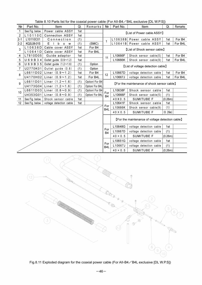
-46-
Table 8.10 Parts list for the coaxial power cable (For AII-B4/B4L exclusive [DL W.P.S])
№ Part No. Item Qt. R em a r k s № Part No. Item Qt. Remarks
1 See Fig. below. Power cable ASSY 1st
2 L 1 0 1 1 0 C Connection ASSY 1st 【List of Power cable ASSY】
2-1 L10110C01 C o n n e c t i o n (1) L 1 0 6 3 8 B P o w e r c a b l e A S S Y 1st For B4
2-2 KQ2L08-01S E l b o w (1) (SMC) 1
L 1 0 6 4 1 B P o w e r c a b l e A S S Y 1st For B4L
L 1 0 6 3 8 D Cable cover ASSY 1st For B4 3
L 1 0 6 4 1 D Cable cover ASSY 1st For B4L 【List of Shock sensor cable】
4 L 7 8 1 0 D0 5 Gu ide a dap to r 1st L10666F Shock senso r cab le (5 ) 1st For B4
5 U 6 9 B 3 4 Outlet guide(0.9~1.2) 1st 11
L10666K Shock senso r cab le (9 ) 1st For B4L
6 U 6 9 B 3 5 Outlet guide(1.2~1.6) (1) Option
7 U2770K01 O u t l e t g u i d e(0 . 8) (1) Option 【List of voltage detection cable】
L 6 6 11 D 0 2 L iner(0.9~1.2) 1st For B4 L10667D vol tage detect ion cable 1st For B48
U417 0H0 2 L iner(0.9~1.2) 1st For B4L 12
L10667J vol tage detect ion cable 1st For B4L
L 6 6 11 D 0 1 L iner(1.2~1.6) (1) Option/ For B49
U4173G04 L iner(1.2~1.6) (1) Option/ For B4L【For the maintenance of shock sensor cable】
L 6 6 11 D 0 3 L iner(0.8~0.9) (1) Option/ For B4 L10638F S h o c k s e n s o r c a b l e 1st 10
U4353G01 L iner(0.8~0.9) (1) Option/ For B4L L10666F Shock senso r cab le (5 ) (1)
11 See Fig. below. S h o c k s e n s o r c a b l e 1st
ForB4
4 0 X 0 . 5 SUMITUBE F (0.26m)
12 See Fig. below. voltage detection cable 1st L10641F S h o c k s e n s o r c a b l e 1st
L10666K Shock senso r cab le (9 ) (1) For B4L
4 0 X 0 . 5 SUMITUBE F (0.26m)
【For the maintenance of voltage detection cable】
L10648G vol tage detect ion cable 1st
L10667D vol tage detect ion cable (1) ForB4
4 0 × 0 . 5 SUMITUBE F (0.26m)
L10651G vol tage detect ion cable 1st
L10667J vol tage detect ion cable (1)
For B4L
4 0 × 0 . 5 SUMITUBE F (0.26m)
Fig.8.11 Exploded diagram for the coaxial power cable (For AII-B4/B4L exclusive [DL W.P.S])
Instruction Manual for CO2 /MAG Welding Torch
RT3500S/ H/ L RT5000S/ H/ L
RTW5000S/ H/ L RZ3500S/H/L
N o . 1 L 1 0 6 0 3 - 1 September. ,2008 1st edition 1st copy
N o . 1 L 1 0 6 0 3 - 2 October. ,2009 2nd edition 2nd copy