Embed Size (px)
Citation preview
agnieszka porowska*, andrzej flaga*
wind-TUnnel Modelling of THe pHenoMenon of railwaY wagons rolling oVer Under sTrong Crosswind aCTion
Modelowanie w TUnelU aerodYnaMiCznYM zjawiska wywracania się wagonów kolejowych pod wpływem silnego
poprzeCznego wiaTrU
a b s t r a c t
This paper deals with the derivation of similarity criteria for the phenomenon of railway wagons rolling over when exposed to strong crosswinds. Utilizing these criteria, the authorial method for the determination of the aerodynamic coefficient of the rollover moment is also presented in the paper.
Keywords: railway vehicle, across strong wind, vehicle roll-over
s t r e s z c z e n i e
artykuł przedstawia sposób wyprowadzenia kryteriów podobieństwa dla zjawiska wywracania się wagonów kolejowych pod wpływem silnego poprzecznego wiatru. z użyciem tych kryteriów przed-stawiono również autorską metodę wyznaczania współczynnika aerodynamicznego momentu obro-towego pojazdu szynowego.
Słowa kluczowe: pojazd szynowy, silny wiatr poprzeczny, wywracanie się pojazdów
DOI: 10.4467/2353737XCT.15.123.4160
* faculty of Civil engineering, Cracow University of Technology, poland.
36
1. Introduction
railway vehicles in general and especially empty freight wagons as well as empty containers transported on freight wagon platforms may roll over when subjected to strong winds that blow transversely to the direction of the train movement.
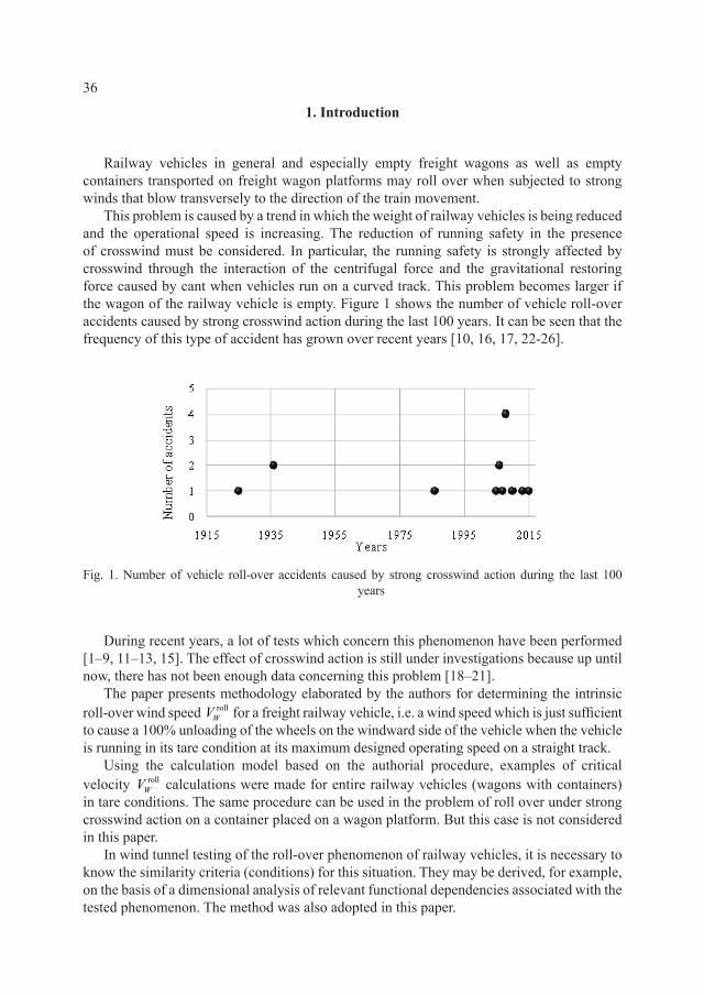
This problem is caused by a trend in which the weight of railway vehicles is being reduced and the operational speed is increasing. The reduction of running safety in the presence of crosswind must be considered. in particular, the running safety is strongly affected by crosswind through the interaction of the centrifugal force and the gravitational restoring force caused by cant when vehicles run on a curved track. This problem becomes larger if the wagon of the railway vehicle is empty. figure 1 shows the number of vehicle roll-over accidents caused by strong crosswind action during the last 100 years. it can be seen that the frequency of this type of accident has grown over recent years [10, 16, 17, 22-26].
fig. 1. number of vehicle roll-over accidents caused by strong crosswind action during the last 100 years
during recent years, a lot of tests which concern this phenomenon have been performed [1–9, 11–13, 15]. The effect of crosswind action is still under investigations because up until now, there has not been enough data concerning this problem [18–21].
The paper presents methodology elaborated by the authors for determining the intrinsic roll-over wind speed roll
WV for a freight railway vehicle, i.e. a wind speed which is just sufficient to cause a 100% unloading of the wheels on the windward side of the vehicle when the vehicle is running in its tare condition at its maximum designed operating speed on a straight track.
Using the calculation model based on the authorial procedure, examples of critical velocity roll
WV calculations were made for entire railway vehicles (wagons with containers) in tare conditions. The same procedure can be used in the problem of roll over under strong crosswind action on a container placed on a wagon platform. But this case is not considered in this paper.
in wind tunnel testing of the roll-over phenomenon of railway vehicles, it is necessary to know the similarity criteria (conditions) for this situation. They may be derived, for example, on the basis of a dimensional analysis of relevant functional dependencies associated with the tested phenomenon. The method was also adopted in this paper.
37
furthermore, using these criteria and their related functional dependencies, the authorial method for determining the roll-over aerodynamic moment coefficient of a railway vehicle,
,AM leeC , is presented.
2. Sets of vehicle roll-over phenomenon parameters
2.1. outline of dimensional analysis
in describing physical objects, events or phenomena quantitatively, one may refer to numerical values of base quantities and also introduce numbers derived by inserting these values into certain mathematical formulas, expressions, relationships, etc.
each of the derived quantities can be written in a power-low form [8, 9, 14]
11
i iki i ka a A Aα α= … (1)
where: ai – derived quantity; ia – dimensionless quantity (number); A1 … Ak – dimensional base; αi1 – real number, whose values distinguish one type of derived quantity from another.
Hence, dimensionless quantity can be written as a quotient:
1
1i ik
ki
iaA A
a α α=…
(2)
where the dimensions of dimensional quantity ai and the product of dimensions 11
i ikkA Aα α…
are the same. dimensionless quantities are the same regardless of the object scale:
iM iNa a= (3)
where: M – model of the object, N – object at a 1:1 scale.The above relationship can be written in another way:
iM iNΠ = Π (4)
Taking into account the presented relations, one can set the following relationship:
( )
( )11
1
1
11
1
1
( )1 1
( )
i iki ik
i ik
i ik
i
kk i M NM
i k Mi N
k N
aA AA A a
a A AaA A
α αα α
α α
α α
…… = → =
… …
(5)
38
1
1
1i ik
ai
A Ak
kk kα α =
… (6)
where:
( )( )i M
aii N
ak
a= (7)
is the scale of derived quantities ai
finally, the relationship for the scales can be obtained:
( )1
1
1
11
1( )
i ik
i ik
i ik
k Nai A Ak
k M
A Ak k k
A A
α α
α αα α
…= … =
…, (8)
after this short introduction to dimensional analysis, one can now focus on the analyzed case of railway wagons.
2.2. set of parameters characterizing inflowing air crosswind to the running train
The initial step in the dimensional analysis of the problem of overturning railway vehicles under strong crosswind is to determine sets of all quantities related to this phenomenon on the basis of knowledge and previous measurements [8, 9, 11, 14, 16].
The first set includes parameters describing inflowing air in a strong crosswind relative to the running train:
( ) ( ), , , , , , , ,a W R ref b vW V V V V I= ρ ν ϕ β (9)
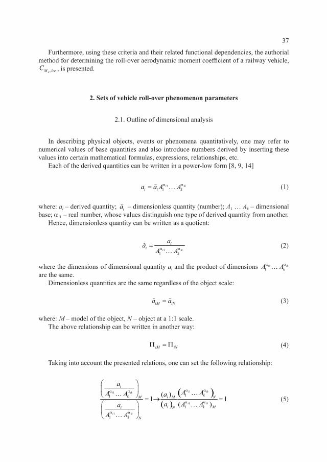
where: ρa – air mass density (1,225 kg/m3); ν – kinematic viscosity of atmospheric air; VW – peak (gust) wind velocity at the top of the vehicle; VR – relative velocity of wind and train running at operating velocity VT; ϕ – angle of wind attack; β – relative angle of wind attack; Vref – mean wind velocity; Vb – basic wind velocity for the given localization according to pn-en 1991-1-4; Iv – turbulence intensity.
relationship between the wind angle and the relative wind angle and the three vectors of velocities is shown in fig. 2.
2.3. set of vehicle describing parameters treated as dimensionless
The next set of quantities concerns parameters which describe the vehicle and are treated as dimensionless. They identify the vehicle and its location in the convoy, together with adjacent vehicles. These are as follows:
39
Fig. 2. relationship between the wind angle φ and resultant (relative) wind angle β [10]
ID = vehicle type, level of corner rounding; aerodynamic character of vehicle geometry (streamlined, intermediate, non-streamlined), presence or not of adjacent vehicles in front of or behind the vehicle, etc.
2.4. set of vehicle geometric parameters
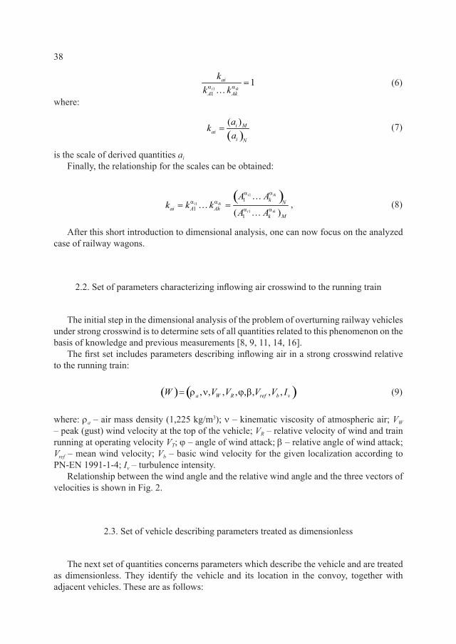
another set of quantities include parameters which allow describing features of vehicle geometry. fig. 3 shows examples of these.
( ) ( ),G A H= (10)
where: A – vehicle side area (reference area); H – mean longitudinal roof height above axle centerline (reference height).
a)
b)
c)
fig. 3. Vehicle side area A and vehicle reference height H for different types of vehicles [19]
40
2.5. set of aerodynamic and mechanical vehicle parameters
The last set which is presented in this paper includes parameters of aerodynamic and mechanical vehicle responses to strong crosswind action. These are as follows:
( ) ( , , , , )Ax Az A R TO F F M M V= , (11)
where: FAx – vehicle aerodynamic drag force; FAz – vehicle aerodynamic lift force; MA – vehicle aerodynamic rolling moment with respect to the resolution point O; MR – vehicle restoring moment due to vehicle weight with respect to the top point of the leeward rail; VT – operating speed of the running train.
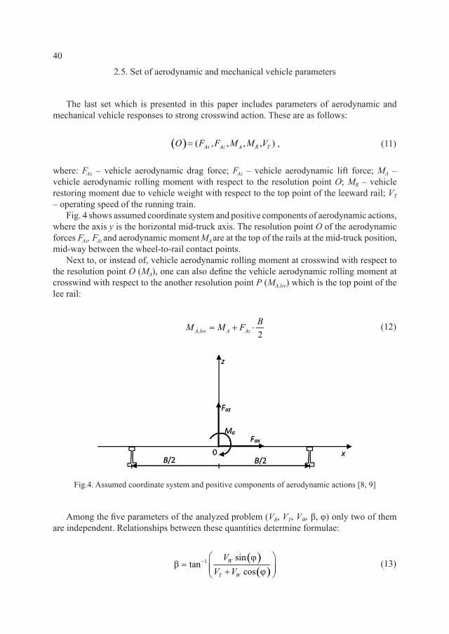
fig. 4 shows assumed coordinate system and positive components of aerodynamic actions, where the axis y is the horizontal mid-truck axis. The resolution point O of the aerodynamic forces FAx, FAz and aerodynamic moment MA are at the top of the rails at the mid-truck position, mid-way between the wheel-to-rail contact points.
next to, or instead of, vehicle aerodynamic rolling moment at crosswind with respect to the resolution point O (MA), one can also define the vehicle aerodynamic rolling moment at crosswind with respect to the another resolution point P (MA,lee) which is the top point of the lee rail:
, 2A lee A AzBM M F+ ⋅= (12)
fig.4. assumed coordinate system and positive components of aerodynamic actions [8, 9]
among the five parameters of the analyzed problem (VR, VT, VW, β, φ) only two of them are independent. relationships between these quantities determine formulae:
( )( )
1 sinco
ns
ta W
T W
VV V
− ϕβ = + ϕ
(13)
41
( )
( )1 sin
costan R
R T
VV V
− βϕ = β −
(14)
( )( )
sinsinR
W
VV
β=
ϕ (15)
3. The possible dimension and dimensionless functional relationships of the analyzed problem
3.1. similarity criteria in case of problem i
Taking into account the above sets of parameters, one can determine possible dimension and dimensionless functional relationships of the analyzed problem, firstly in the case of the problem which concerns vehicle roll over aerodynamic moment coefficient. This problem will be referred to as problem i.
Vehicle roll over aerodynamic moment depends on several quantities:
( )( ), , , , , , , , ;A lee A lee a RM M V A H ID= ρ ν ϕ β (16)
The next step of dimensional analysis is to determine the dimensional base. one can assume that the dimensional base constitutes: ρa – air mass density (1,225 kg/m3), VR – relative velocity of wind and train running at operating velocity VT, H – reference height.
Taking into account this base and theorem Π [14] of dimensional analysis the previous relationship one can bring to dimensionless relationship in which appear the following quantities:
( )( ), , , , , ; ,A lee A lee RM M Re ID= β ϕ λ
(17)
where: ,, 2 3 A lee
A leea R
MM
V H=ρ
– vehicle roll-over aerodynamic moment coefficient; reR = VRH/ν
– vehicle reynolds number; λ = A/H 2 – vehicle slenderness.instead of aerodynamic coefficient ,A leeM
, one can more frequently find this coefficient defined in another way:
,,
212
A
A leeM lee
a R
MC
V AH=
ρ (18)
42
finally, one can write the dimensionless relationship of problem i as follows:
( )( ), , , , , ; .A AM lee M lee RC C Re ID= β ϕ λ (19)
all dimensionless quantities appearing in this dimensionless functional relationship constitute determined similarity criteria in the case of problem i.
3.2. similarity criteria in the case of problem ii
The second problem in these considerations concerns dimensionless relative critical wind velocity. firstly, the set of quantities related to intrinsic roll-over wind speed should be determined:
( )( ), , , , , , , , , ; ,roll roll roll rollR R a ref b v RV V V V I A H M ID= ρ ν β ϕ (20)
where: rollWV – intrinsic roll-over wind speed – the wind speed which is just sufficient to cause
a 100% unloading of the wheels on the windward side of the vehicle when the vehicle is running in its tare condition at its maximum design operating speed on a straight track.
in general, one can investigate and analyze different cases of train speeds ( )* 0,T TV V∈ where the case * 0TV = refers to the stopped train.
in the limit (critical) situation, the vehicle roll-over aerodynamic moment ,rollA leeM caused
by crosswind is balanced by the vehicle restoring moment MR, resulting from gravitational forces acting on the vehicle.
let us assume dimensional base in this case as: ρa – air mass density (1,225 kg/m3), Vb – basic wind velocity for the given localization [18], H – reference height.after this assumption, one can finally obtain the dimensionless relationship of problem ii:
( )( ), , , , ; ,roll roll RR R
roll rollb MV V
C C Re C ID= β ϕ λ (21)
where: rollR
rollR
Vb
VCV
= – dimensionless relative critical wind velocity; 21
2
R
RM
a b
MCV AH
=ρ
– dimensionless vehicle restoring moment coefficient (taking into account remarks as in the case of dimensionless vehicle roll-over aerodynamic moment coefficient ,A leeM
and dimensionless roll-over aerodynamic moment coefficient ,AM leeC ); βroll, ϕroll, λ – as before but in the limit (critical) situation.
all dimensionless quantities appearing in this dimensionless functional relationship constitute determined similarity criteria (numbers) in the case of problem ii which should be fulfilled in model testing.
43
4. Problems of similarity criteria fulfillment in wind tunnel model tests and basic simplification assumptions in investigations
There are problems with the fulfilment of some of the similarity criteria in wind tunnel model tests. as a result, it is necessary to use simplification assumptions which are usually assumed in investigations.
There are following problems connected with wind tunnel tests in the case of railway vehicle roll over when subjected to strong crosswind: tests on the moving train, fulfillment of reynolds number.
The first problem concerns the question of how to perform investigations on a scale model of the vehicle together with a part of a train which is moving with respect to the air stream in the working section of wind tunnel.
on the other hand, there is no problem with the realization of a suitable angle of wind attack on a model, this is because the tested model is placed on the rotating table of the wind tunnel working section.
it is common practice to simplify this problem by performing tests on motionless rigidly fixed models and assume that: inflowing air stream has the velocity: exp
W RV V= , ( ),exp roll rollW RV V= ;
the angle of air stream attack is: ϕ = β , roll rollϕ = β .The second general problem of similarity criteria fulfillment in the wind tunnel model tests
is the fulfillment of the reynolds number. This number takes into consideration the influence of air viscous forces on aerodynamic actions caused by the wind blowing transversally on to a railway vehicle.
a simple example may be considered: if the geometric scale of model kH = 1/5, then from the reynolds criterion it results that the velocity scale kV = 5. This means that in the wind tunnel, the velocity of air stream should be five times greater than in nature. This is very hard to make in practice.
However, in the case of weakly streamlined bodies – as is the case for railway vehicles in the draft of wagons – the dependence of aerodynamic coefficients on the reynolds number, i.e. the flow-over crisis and connected with it, the different values of aerodynamic coefficients in subcritical, critical, supercritical and transcritical ranges of reynolds number do not take place in practice.
it is commonly assumed that unfulfillment of this criterion in wind tunnel tests does not lead to essential mistakes in experimental results.
after these simplifications, instead of considering functions (19 and 21): ( )( ), , , , , ;
A AM lee M lee RC C Re ID= β ϕ λ and ( )( , , , , , ; ,roll roll RR R
roll roll rollb W MV V
C C Re V C ID= β ϕ λ
, the approximate functions evaluating the primary functions are considered:
( )( ), , , ;A A
exp expM lee M leeC C ID= ϕ λ (22)
and
( )( ), , , , ;exp roll exp roll RW W
rollMV V
C C C ID= ϕ λ (23)
44
5. Examples of similarity criteria fulfillment for the case of railway wagons rolling over when subjected to strong crosswind action
5.1. Vehicle restoring moment
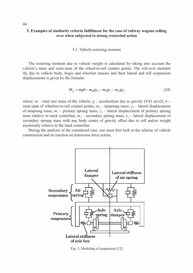
The restoring moment due to vehicle weight is calculated by taking into account the vehicle’s mass and semi-span of the wheel-to-rail contact points. The roll-over moment MR due to vehicle body, bogie and wheelset masses and their lateral and roll suspension displacements is given by the formula:
0 0 1 1 2 2RM mgb m gy m gy m gy= − − − (24)
where: m – total tare mass of the vehicle; g – acceleration due to gravity (9.81 m/s2); b – semi-span of wheelset-to-rail contact points; m0 – unsprung mass; y0 – lateral displacement of unsprung mass; m1 – primary sprung mass; y1 – lateral displacement of primary sprung mass relative to track centerline; m2 – secondary sprung mass; y2 – lateral displacement of secondary sprung mass with any body center of gravity offset due to roll and/or weight asymmetry relative to the track centerline.
during the analysis of the considered case, one must first look at the scheme of vehicle construction and its reaction on transverse force action.
fig. 5. Modeling of suspension [12]
45
The fig. 5 shows the scheme of suspension in a railway wagon.The wheelset constitutes the unsprung mass. Train wheels are based directly on the rails.
The lateral displacement of the unsprung mass (y0) is always considered to be zero as the roll-over moment is calculated about the point of contact of the wheelset itself on the rail head. The chassis of the wagon is mounted to the wheelset by horizontal and vertical springs which allow horizontal and vertical displacements. The chassis is the primary sprung mass. other vehicle elements are attached to the chassis also by horizontal and vertical springs, which also allow horizontal and vertical displacements. The container with the other elements which are under the chassis are the secondary sprung mass.
The displacements of sprung masses are the effect of acting lateral force, i.e. wind action which is considered here. These displacements depend on the type of railway vehicle and the velocity of atmospheric air acting upon it.
The lateral displacements of the primary and secondary sprung masses (y1 and y2) can be taken as the maximum (metal to metal) displacements including the effects of roll at the height of the center of gravity.
returning to define the railway restoring moment, its dimensional base should first be determined. in the event of the rolling over of railway wagons under strong crosswind action, the dimensional base will consist of the following quantities: ρa – density of atmospheric air; Vb – basic wind velocity; H – height of railway vehicle.
The next step of dimensional analysis is to set its dimensionless quantity on the basis of the assumed dimensional base:
0 0 1 1 2 22 3 2 3 1R
Ra b a b
m yM m y m ymgbm b m
Mb m bV H V H
= = − − − ρ ρ
(25)
where: 2 3a bV Hρ – the product quantities of the dimensional base defining the dimensions of
railway restoring moment.particular components of the above equation are presented as dimensionless quantities:
*2 3R
a
mgbL
MV
=ρ
– dimensionless vehicle restoring moment; 0 0 /m mm= – dimensionless
unsprung mass; 1 1 / mm m= – dimensionless primary sprung mass; 2 2 /m mm= – dimensionless secondary sprung mass; 0 0 /y by= – dimensionless lateral displacement of unsprung mass; 1 1 /y by= – dimensionless lateral displacement of primary sprung mass;
2 2 /y by= – dimensionless lateral displacement of secondary sprung mass.The relations listed above constitute similarity numbers, which should be fulfilled in wind
tunnel model tests, so to be true the below relationship:
* *RM RNM M=
(26)
which implies the ratio of the railway restoring moment in the natural and model scale:
*
* 1RM
RN
MM
=
(27)
46
2 32 3 1
b
a b
m g bm b V H
V H
k k kk k k k
k k kρ
= → = (28)
because: kg = 1 – gravitational scale is equal to one because gravitational force is the same in the model and natural scale (tests will be performed in normal gravitational conditions);
1a
kρ = – scale of density of atmospheric air is equal to one because density of atmospheric air is the same in the model and natural scale.
finally, the similarity scales resulting from the above criteria can be written as follows:
3
2 2 2 ;b b
Hm V m V H
b
kk k k k kk
= → = (29)
where: km – scale of mass; bVk – scale of base wind velocity which acts on the railway
vehicle; kH, kb – scale of railway vehicle geometry. kH = kb.scales of particular masses of railway vehicle:
0 1 2; ; m m m m m mk k k k k k= = = .
scales of geometry of particular railway vehicle elements displacements: 0 1 2
; ; y b y b y bk k k k k k= = = .one can now consider two cases of the railway train model performing which will be
tested in a wind tunnel and similarity criteria which should be fulfilled in each of them.
5.2. examples of similarity criteria fulfillment
First caseassumption: the model is made of the same material as the real object.The particular scales can be written as follows: 1
mmM mN kρρ = ρ → = – on the basis of assumption; kH = kb – particular lengths are in relevant proportions – geometrical scale is
the same for all of the dimensions of the model elements; 3MH
N
k kΩ
Ω= =
Ω – volume scale;
mm mm k k kρ Ω= ρ Ω→ = – mass scale.
after substitution of the scale, the relation can be presented in such a form:
2 2 2 m b b bV H V H V Hk k k k k k k kρ Ω = → = → = (30)
where: kH – geometrical scale of the model – assumed scale of the model; bVk – scale of the
wind velocity, which acts on the model tested in wind tunnel, determined in accordance to the above relationship.
on the basis of relations determining dependence between the described two scales, a simple example can be shown:
assumption: the model is performed at a geometric scale – 1:15, so kH = 1/15.
Hence, one can easily determine velocity scale: 1 0,258
15bV Hk k= = ≅ .
47
Therefore, if the wind velocity in nature is: VbN = 22 m/s (which refers to the basic wind velocity in the first zone of wind load in poland according to pn-en 1991-1-4), the velocity of inflowing air in the wind tunnel which is acting on the model must be: VbM ≅ 5.68 m/s
Second caseassumption: the model is made of different material to the object in natural scale.Mass can be described by the following equation:
m m m m mS S
m d d dxdydz ddS d dSΩ Ω Ω
= ρ Ω = ρ Ω = ρ = ρ = ρ∫ ∫ ∫ ∫ ∫ (31)
where: d – the wall thickness.after writing this equation with using the scales can be obtained:
2 mm d H
S
d dS k k kρρ →∫ (32)
as it was derived before, the scale of mass can also be written in a different way:
2 2 2 2 m b m b b m md H V H d V V d Hk k k k k k k k k k k k kρ ρ ρ ρ= → = → = = (33)
kd – geometric scale of the model – assumed scale of the model (kd = kH); m
kρ – scale of material density – scale dependent on density of material used to perform the model;
bVk – as before.
similar to the first case, one can present a simple example but with such a difference that now three scales are taken into consideration.
assumption: the model is performed at a geometric scale – 1:15, so kH = 1/15; the model is performed of material with density 1.5 times smaller than the object at a 1:1 scale. hence,
there is: 1 0.67
1,5 m
mM
mN
kρρ
= → ≅ρ
.
on this basis, one can define the scale of wind velocity: 0.67 0.067 0.211b mV Hk k kρ= = ⋅ ≅ .
Therefore, if the wind velocity in nature is: VbN = 22 m/s , the velocity of inflowing air in wind tunnel which is acting on the model must be: VbM ≅ 4.64 m/s.
These two cases show the importance of adequate choice of similarity scales which should be satisfied by the model. Two different assumptions with respect to the similarity criteria fulfillment proceed to different ways of the model and test execution.
6. Authorial method of determination the vehicle roll-over aerodynamic moment coefficient under strong crosswind action
The vehicle roll-over aerodynamic moment coefficient ,A
rollM leeC can be determined on the
basis of experimental results of the intrinisic roll-over wind velocity ,exp rollWV obtained in wind
48
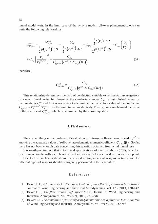
tunnel model tests. in the limit case of the vehicle model roll-over phenomenon, one can write the following relationships:
( ) ( )
( )
( )
( )( ),
22
,, 2 2 2
2
, 2
1M 2
1 1 12 2 2
, , ;
A R R
R
Rexp roll RW
roll bA leeroll bR
M lee M M rollroll roll roll R
R R R
MbM exp roll roll
W MV
V AHM VC C C
VV AH V AH V AH
CVC
V C C ID
ρ = = = =
ρ ρ ρ
≅ =
ϕ λ (34)
therefore:
( )( ),
, 2.
, , ;R
Aexp roll RW
MrollM lee roll
MV
CC
C C ID≅
ϕ λ (35)
This relationship determines the way of conducting suitable experimental investigations in a wind tunnel. after fulfillment of the similarity number
RMC at established values of the quantities ϕroll and λ, it is necessary to determine the respective value of the coefficient
,, /exp roll
W
exp roll expW bV
C V V= from the wind tunnel model tests. finally, one can obtained the value of the coefficient ,A
rollM leeC which is determined by the above equation.
7. Final remarks
The crucial thing in the problem of evaluation of intrinsic roll-over wind speed rollWV is
knowing the adequate values of roll-over aerodynamic moment coefficient ( ),M leeC β . so far, there has not been enough data concerning this question obtained from wind tunnel tests.
it is worth pointing out that in technical specifications of interoperability (Tsi), the effect of crosswind on the roll-over phenomena of railway vehicles is considered as an open point.
due to this, such investigations for several arrangements of wagons in trains and for different types of wagons should be urgently performed in the near future.
r e f e r e n c e s
[1] Baker C.j., A framework for the consideration of the effects of crosswinds on trains, journal of wind engineering and industrial aerodynamics, Vol. 123, 2013, 130-142.
[2] Baker C.j., The flow around high speed trains, journal of wind engineering and industrial aerodynamics, Vol. 98(6-7), 2010, 277-298.
[3] Baker C.j., The simulation of unsteady aerodynamic crosswind forces on trains, journal of wind engineering and industrial aerodynamics, Vol. 98(2), 2010, 88-99.
49
[4] Bocciolone M., Cheli f., Corradi r., Muggiasca s., Tomasini g., Crosswind action on rail vehicles: Wind tunnel experimental analyses, journal of wind engineering and industrial aerodynamics, Vol. 96(5), 2008, 584-610.
[5] Carrarini a., Reliability based analysis of the crosswind stability of railway vehicles, journal of wind engineering and industrial aerodynamics, Vol. 95(7), 2007, 493-509.
[6] Cheli f., giappino s., Tomasini g., Villani M., zanetti g., Aerodynamic loads on lightweight railway vehicles for the evaluation of rollover risk, proc. 2nd international Conference on railway Technology: research, development and Maintenance, 2014.
[7] deliancourt f., sicot C., aguinaga s., Boree j., Bouchet j-p., Simulation of details in wind tunnel testing: application to railway trains, proc. 48th applied aerodynamics symposium saint-louis, france, 25-27 March 2013.
[8] flaga a., Resistance of freight railway vehicles to roll-over in strong winds, Cracow University of Technology, Cracow 2014.
[9] flaga a., Basic principles and theorems of dimensional analysis and theory of model similarity of physical phenomena, proc. 7th international symposium on environmental effects on Buildings ad people: actions, influences, interactions, discomfort, lublin-kraków 2014.
[10] flaga a., Expert opinion on resistance of railway vehicles to roll-over in gales and on possibility of blowing off 20ft and 40ft freight containers from S04a FEA-B wagons running in the draft of wagons at maximum velocity 120 km/h, wagony Świdnica s.a., Świdnica 2013.
[11] flaga a., porowska a., Charakterystyka zjawiska wywracania się wagonów przy silnym wietrze oraz metoda wyznaczania współczynnika aerodynamicznego momentu obrotowego pojazdu szynowego, inżynieria i Budownictwo, Vol. 12, 2014, 689-691.
[12] shimada k., Tanifuji, k., Influence of cross wind on the running safety of railway vehicle running on curve at low speed, j-rail, 2008, 441-444.
[13] proppe C., wetzel C., Overturning probability of railway vehicles under wind gust loads, iUTaM symposium on dynamics and Control of nonlinear systems with Uncertainty, 2007, 23-32.
[14] sonin a.a., The physical basis of dimensional analysis, department of Mechanical engineering MiT, Cambridge 2001.
[15] suzuki M., Tanemoto k., Maeda T., Aerodynamic characteristics of train/vehicles under cross winds, journal of wind engineering and industrial aerodynamics, Vol. 91(1-2), 2003, 209-218.
[16] Terry j., Investigation of freight vehicle aerodynamic performance in accordance with GM/RT 2142 Resistance of Railway Vehicles to Roll-Over in Gales, rssB, 2012.
[17] raiB, Detachement of containers from freight wagons near Cheddington and Hardendale, department of Transport, 1 March 2008, raport 12/2009 May 2009.
[18] pn-en 1991-1-4 eurocode 1 – actions on structures. part 1-4: general actions - wind actions, 2008.
[19] gM/rT2142 issue 3, resistance of railway Vehicles to roll-over in gales, 2009;[20] pn-en 140-67-6:2010 kolejnictwo − aerodynamika − część 6: wymagania
i procedury badań aerodynamicznych oddziaływania wiatru bocznego.[21] 2008/232/we specyfikacje techniczne interoperacyjności podsystemu „Tabor”
transeuropejskiego systemu kolei dużych prędkości (notyfikowana jako dokument nr C, 2008), 648.

50
[22] http://www.raib.gov.uk[23] http://www.railwaysarchive.co.uk[24] http://www.irsc2014.org[25] http://www.intlrailsafety.com[26] http://en.wikipedia.org/wiki/list_of_wind-related_railway_accidents