Embed Size (px)
Citation preview
WIRE JACKETING
WITH FIRESTONE
NYLON 6

TABLE OF CONTENTS SECTION PAGE
I. FIRESTONE NYLON 6 FOR WIRE APLICATIONS…………………………….. 1
II. TYPICAL PROPERTIES OF FIRESTONE NYLON 6 ………………………….... 2
III. EXTRUSION EQUIPMENT FOR FIRESTONE NYLON
A. WIRE JACKETING LINES ……………………………………………………… 3
B. EXTRUDER ………………………………………………………………………. 5
C. SCREW DESIGN ………………………………………………………………… 5
D. CROSSHEAD ……………………………………………………………………. 7
E. WIRE COATING …………………………………………………………………. 7
IV. PROCESSING CONDITIONS FOR FIRESTONE NYLON 6
A. QUENCHING ……………………………………………………………………… 9
B. MELT TEMPERATURE …………………………………………………………..11
C. TYPICAL PROCESSING CONDITIONS ………………………………………..11
V. PROBLEM SOLVING GUIDE – FIRESTONE NYLON 6
RESIN, TUBING DIE ……………………………………………………………………12
I. FIRESTONE NYLON 6 FOR WIRE APPLICATIONS Firestone offers nylon 6 resins which are particularly suitable for wire jacketing applications. Their outstanding mechanical properties make them especially desirable, since the primary function of a nylon jacket is to provide mechanical protection for insulation. Nylon 6 is a relatively stiff material but it will absorb a considerable amount of moisture which has a plasticizing and toughening effect. The melting point is sufficiently high that it retains its useful properties at elevated service temperatures, but low enough to permit excellent processing.
A nylon jacket over the wire insulation protects it from cut –through and abrasion during conduit pull through. It also reduces the force required to pull the wires through conduit and provides resistance to grease, oil, gasoline and other hydrocarbons. Firestone wire jacketing grades nylon 6 are stabilized for resistance to thermal and/or actinic degradation.
When a nylon jacket is used to protect the insulation, the thickness of the primary insulator can be reduced to that sufficient for electrical insulation only. This permits the jacket wire construction to have a smaller outside diameter than the unjacketed construction. As a result, a conduit can contain more jacketed wires of a given current carrying capacity than with a unjacketed wire.
II. TYPICAL PROPERTIES OF FIRESTONE NYLON 6
Parameter Colour
C212-15C
Off white
Heat Stabilized Yes Modified Yes Relative Viscosity Sulfuric Acid 3.2 Formic Acid 82 Moisture % Max 0.08 Chip Size mm 2 x 3.5 Specific Gravity 1.13 ASTM D792 Tensile Strength MPa 79.2 ASTM D638 PSI 11,500 Elongation % 300 ASTM D412 Flex Modulus MPa 2,585 ASTM D790 PSI 375,000 Flex Strength MPa 97 ASTM D790 PSI 14,000 Notched Izod Impact ft.lb/in. 0.9 ASTM D256 Deflection Temp. @ 0.45 MPa / 66 PSI 180°C ASTM D648 @ 1.82 MPa / 264 PSI 65°C Melt Temperature 220°C Approvals UL
III. EXTRUSION EQUIPMENT FOR FIRESTONE NYLON 6
A. WIRE JACKETING LINES
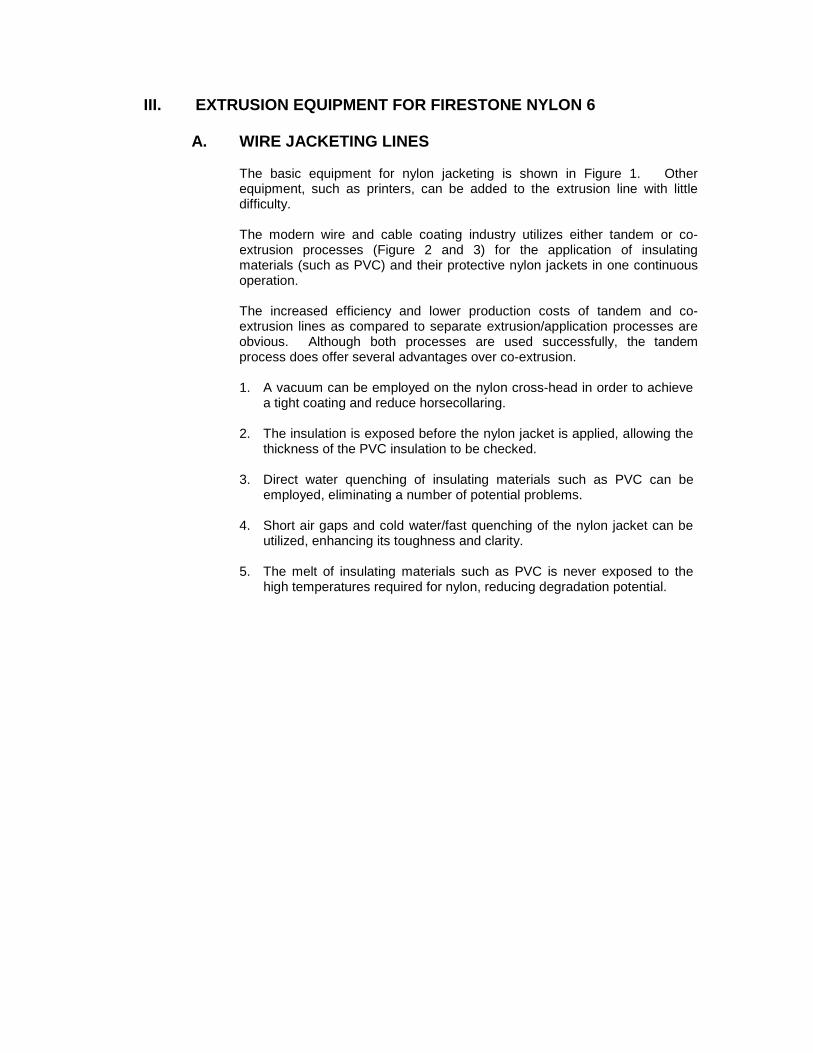
The basic equipment for nylon jacketing is shown in Figure 1. Other equipment, such as printers, can be added to the extrusion line with little difficulty.
The modern wire and cable coating industry utilizes either tandem or co- extrusion processes (Figure 2 and 3) for the application of insulating materials (such as PVC) and their protective nylon jackets in one continuous operation.
The increased efficiency and lower production costs of tandem and co- extrusion lines as compared to separate extrusion/application processes are obvious. Although both processes are used successfully, the tandem process does offer several advantages over co-extrusion.
1. A vacuum can be employed on the nylon cross-head in order to achieve
a tight coating and reduce horsecollaring.
2. The insulation is exposed before the nylon jacket is applied, allowing the thickness of the PVC insulation to be checked.
3. Direct water quenching of insulating materials such as PVC can be
employed, eliminating a number of potential problems.
4. Short air gaps and cold water/fast quenching of the nylon jacket can be utilized, enhancing its toughness and clarity.
5. The melt of insulating materials such as PVC is never exposed to the
high temperatures required for nylon, reducing degradation potential.
SPARK TESTER WINO UP
C00C"l TROUO" j Cr-A-PS-+T-AN --4-
FIGURE 1 TYPICAl.. WIRE JACKETING liNE
PRIMARY EXTRUDER (INSUlATING RESIN)
\ SECONDARY EXTRUDER (NYLON RESIN)
I WINO UP
COOLING TROUGH
t
FIGURE 2 CO-EXTRUSION WIRE JACKETING LINE
CROSSHEAO
SECONDARY EXTRUDER (NYLON JACKET)
t CROSSHEAO
/ cOOLING TROUGH
t
WINO UP
FIGUR E 3
TANDEM EXTRUSION LINE
III. EXTRUSION EQUIPMENT FOR FIRESTONE NYLON 6 (CONT)
B. EXTRUDER
A uniform melt temperature is particularly desirable in wire coating operations. Since the melting point of nylon 6 is high (420°F/216°C), electrically heated extruders with precise temperature controls are required. Although Firestone nylon 6 is currently processed on many types of extruders of various sizes, the extrusion of nylon 6 in wire jacketing operation requires a minimum length-to-diameter (L/D) ratio of 20:1. The long barrel, combined with precise temperature control, provides both adequate time and surface area to obtain a homogenous melt with uniform temperature.
C. SCREW DESIGN
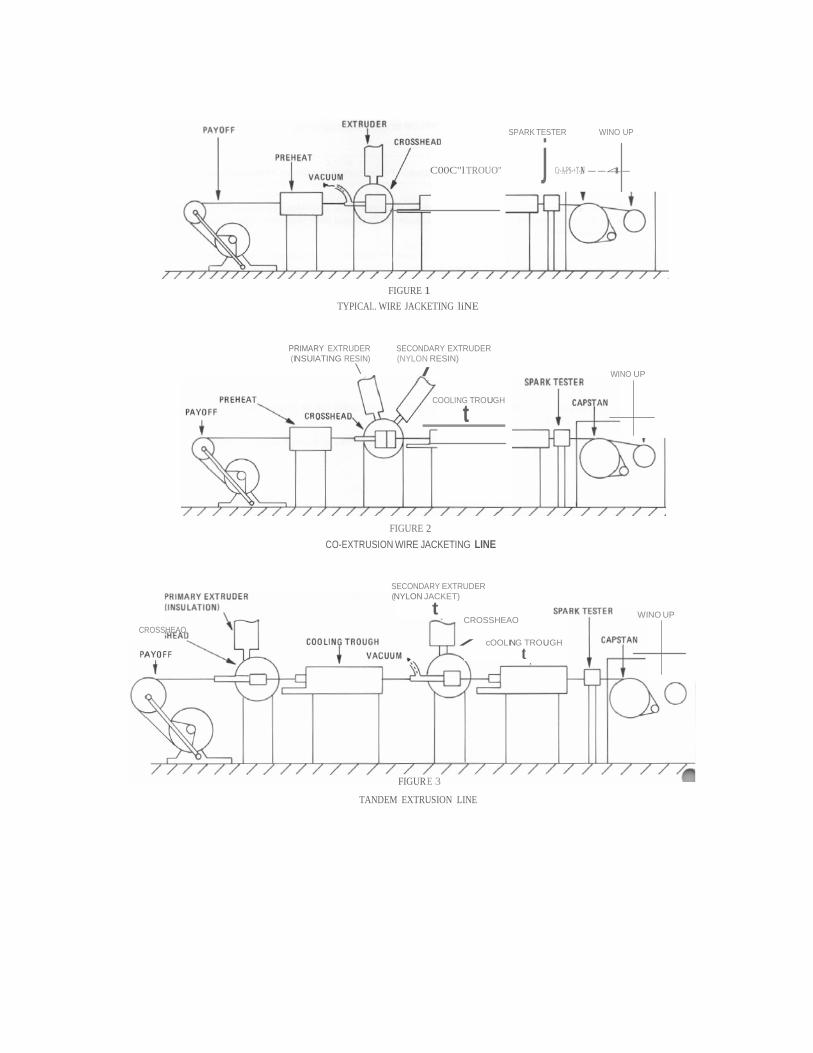
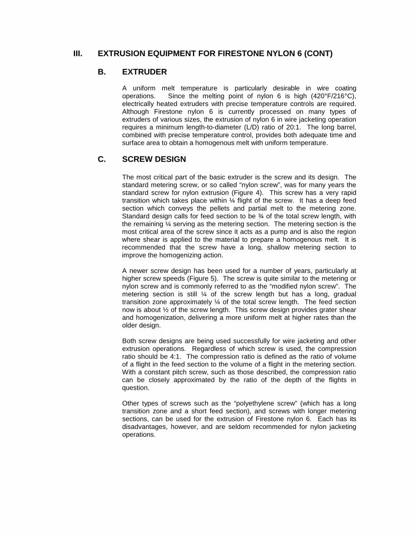
The most critical part of the basic extruder is the screw and its design. The standard metering screw, or so called “nylon screw”, was for many years the standard screw for nylon extrusion (Figure 4). This screw has a very rapid transition which takes place within ¼ flight of the screw. It has a deep feed section which conveys the pellets and partial melt to the metering zone. Standard design calls for feed section to be ¾ of the total screw length, with the remaining ¼ serving as the metering section. The metering section is the most critical area of the screw since it acts as a pump and is also the region where shear is applied to the material to prepare a homogenous melt. It is recommended that the screw have a long, shallow metering section to improve the homogenizing action.
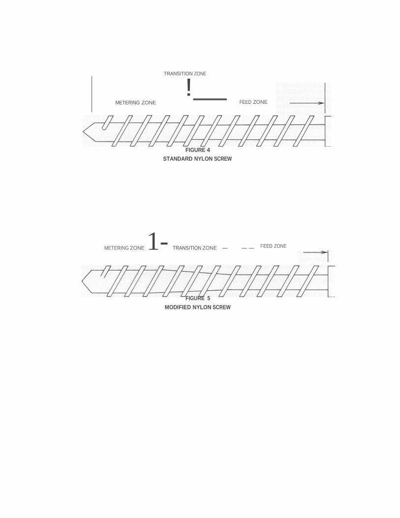
A newer screw design has been used for a number of years, particularly at higher screw speeds (Figure 5). The screw is quite similar to the metering or nylon screw and is commonly referred to as the “modified nylon screw”. The metering section is still ¼ of the screw length but has a long, gradual transition zone approximately ¼ of the total screw length. The feed section now is about ½ of the screw length. This screw design provides grater shear and homogenization, delivering a more uniform melt at higher rates than the older design.
Both screw designs are being used successfully for wire jacketing and other extrusion operations. Regardless of which screw is used, the compression ratio should be 4:1. The compression ratio is defined as the ratio of volume of a flight in the feed section to the volume of a flight in the metering section. With a constant pitch screw, such as those described, the compression ratio can be closely approximated by the ratio of the depth of the flights in question.
Other types of screws such as the “polyethylene screw” (which has a long transition zone and a short feed section), and screws with longer metering sections, can be used for the extrusion of Firestone nylon 6. Each has its disadvantages, however, and are seldom recommended for nylon jacketing operations.
TRANSITION ZONE
! METERING ZONE FEED ZONE
FIGURE 4 STANDARD NYLON SCREW
METERING ZONE 1- TRANSITION ZONE - -- FEED ZONE
FIGURE 5 MODIFIED NYLON SCREW
III. EXTRUSION EQUIPMENT FOR FIRESTONE NYLON 6 (CONT)
D. CROSSHEAD
The crosshead serves as the transition piece between the extruder and the die and supports the guider tip and die. It provides a flow path for the melt as it leaves the extruder and turns in the direction of wire travel. The conventional crosshead for wire jacketing is set at 90 degrees to the extruder. Some newer designs set the crosshead at 30 degrees. The claims for this later design are more streamlined flow and less chance for the material to hang up and degrade. Whichever head is used, the passage should be streamlined and polished.
E. WIRE COATING DIES AND GUIDER TIPS
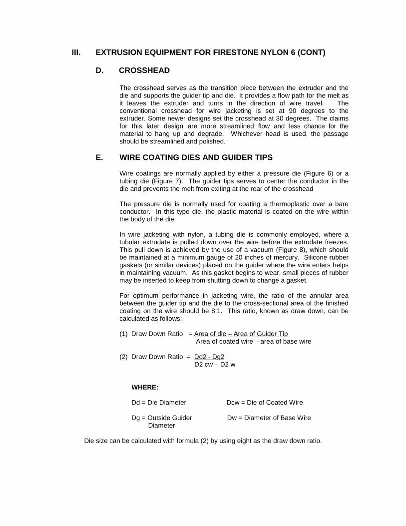
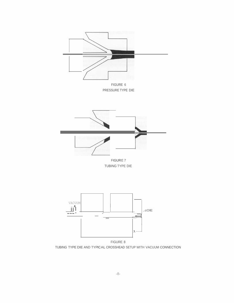
Wire coatings are normally applied by either a pressure die (Figure 6) or a tubing die (Figure 7). The guider tips serves to center the conductor in the die and prevents the melt from exiting at the rear of the crosshead
The pressure die is normally used for coating a thermoplastic over a bare conductor. In this type die, the plastic material is coated on the wire within the body of the die.
In wire jacketing with nylon, a tubing die is commonly employed, where a tubular extrudate is pulled down over the wire before the extrudate freezes. This pull down is achieved by the use of a vacuum (Figure 8), which should be maintained at a minimum gauge of 20 inches of mercury. Silicone rubber gaskets (or similar devices) placed on the guider where the wire enters helps in maintaining vacuum. As this gasket begins to wear, small pieces of rubber may be inserted to keep from shutting down to change a gasket.
For optimum performance in jacketing wire, the ratio of the annular area between the guider tip and the die to the cross-sectional area of the finished coating on the wire should be 8:1. This ratio, known as draw down, can be calculated as follows:
(1) Draw Down Ratio = Area of die – Area of Guider Tip
Area of coated wire – area of base wire
(2) Draw Down Ratio = Dd2 - Dg2 D2 cw – D2 w
WHERE:
Dd = Die Diameter Dcw = Die of Coated Wire
Dg = Outside Guider Dw = Diameter of Base Wire Diameter
Die size can be calculated with formula (2) by using eight as the draw down ratio.
-=
FIGURE 6 PRESSURE TYPE DIE
FIGUR E 7 TUBING TYPE DIE
VACUUM
_jj'l ---·
-
"""
-
..cOlE .........
::;..- 1---
FIGURE 8 TUBING TYPE DIE AND TYPIC AL CROSSHEAD SETUP WITH VACUUM CONNECTION
-8-
III. EXTRUSION EQUIPMENT FOR FIRESTONE NYLON 6 (CONT)
E. WIRE COATING DIES AND GUIDER TIPS (CONT)
The land length of the die and guider tip should be 1 to 1 ½ times the calculated O.D. of the die. Core diameter of the inside guider tip should be approximately 0.010” larger than the wire to be jacketed.
For nylon jacketing, a self-centering type die is used where a large volume of a single construction is involved. An adjustable centering type is employed where more than one construction is involved.
The self centering die has the advantage that it requires no adjustment to center it; however, when wear does occur, longitudinal cracks are encountered in the jacket. These cracks progress with prolonged use to continuous, longitudinal splits. Usually when the die reaches this condition it is impossible to center the jacket, and the entire self centering assembly must be replaced at a high cost to the user.
The advantages of the adjustable centering die are cost flexibility. It can be used for any number of different operations, since the guider tip and die can be readily moved. The part that will show wear with usage will be the die which can be heat treated to reduce wear, or replaced at little expense. When longitudinal cracks are encountered with an adjustable centering die, the centering can be adjusted without interrupting the jacketing operation. Because of their geometrical shape and size, the guider mandrel, guider tip, and die are not as likely to be heat distorted as in the self centering type.
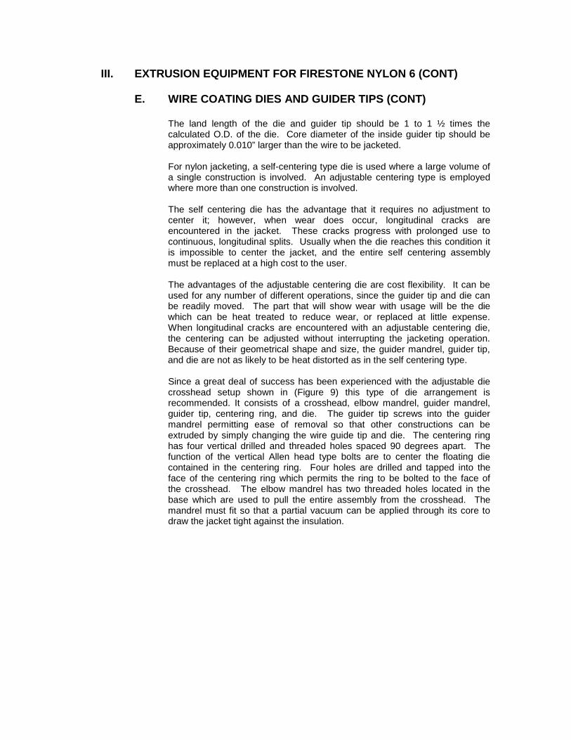
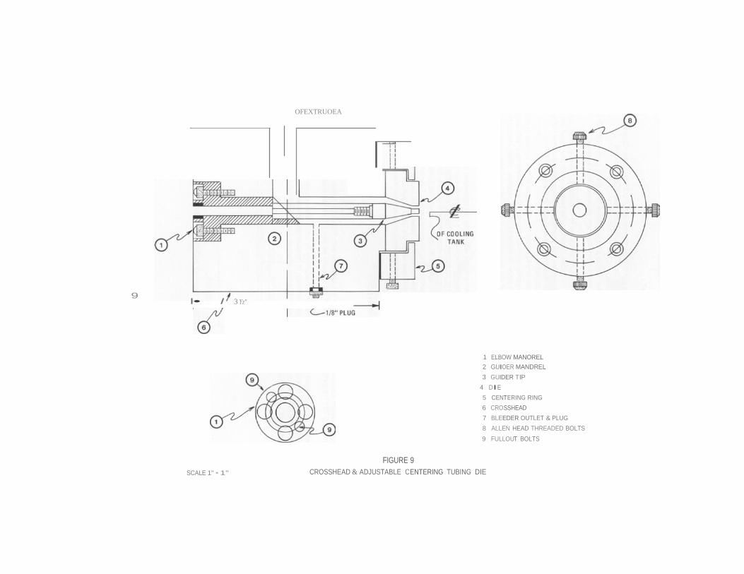
Since a great deal of success has been experienced with the adjustable die crosshead setup shown in (Figure 9) this type of die arrangement is recommended. It consists of a crosshead, elbow mandrel, guider mandrel, guider tip, centering ring, and die. The guider tip screws into the guider mandrel permitting ease of removal so that other constructions can be extruded by simply changing the wire guide tip and die. The centering ring has four vertical drilled and threaded holes spaced 90 degrees apart. The function of the vertical Allen head type bolts are to center the floating die contained in the centering ring. Four holes are drilled and tapped into the face of the centering ring which permits the ring to be bolted to the face of the crosshead. The elbow mandrel has two threaded holes located in the base which are used to pull the entire assembly from the crosshead. The mandrel must fit so that a partial vacuum can be applied through its core to draw the jacket tight against the insulation.
9 I• I 3 Yz"
OFEXTRUOEA
1 ELBOW MANOREL 2 GUIOER MANDREL 3 GUIDER TIP
4 DIE 5 CENTERING RING 6 CROSSHEAD 7 BLEEDER OUTLET & PLUG 8 ALLEN HEAD THREADED BOLTS 9 FULLOUT BOLTS
SCALE 1" • 1"
FIGURE 9 CROSSHEAD & ADJUSTABLE CENTERING TUBING DIE
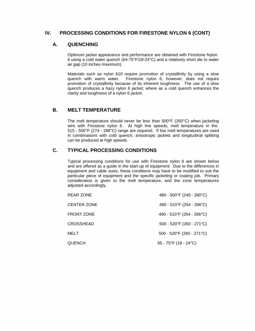
IV. PROCESSING CONDITIONS FOR FIRESTONE NYLON 6 (CONT)
A. QUENCHING
Optimum jacket appearance and performance are obtained with Firestone Nylon 6 using a cold water quench (64-75°F/18-24°C) and a relatively short die to water air gap (10 inches maximum).
Materials such as nylon 610 require promotion of crystallinity by using a slow quench with warm water. Firestone nylon 6, however, does not require promotion of crystallinity because of its inherent toughness. The use of a slow quench produces a hazy nylon 6 jacket; where as a cold quench enhances the clarity and toughness of a nylon 6 jacket.
B. MELT TEMPERATURE
The melt temperature should never be less than 500°F (260°C) when jacketing wire with Firestone nylon 6. At high line speeds, melt temperature in the 515 - 550°F (274 - 288°C) range are required. If low melt temperatures are used in combinations with cold quench, anisotropic jackets and longitudinal splitting can be produced at high speeds.
C. TYPICAL PROCESSING CONDITIONS
Typical processing conditions for use with Firestone nylon 6 are shown below and are offered as a guide in the start-up of equipment. Due to the differences in equipment and cable sizes, these conditions may have to be modified to suit the particular piece of equipment and the specific jacketing or coating job. Primary consideration is given to the melt temperature, and the zone temperatures adjusted accordingly.
REAR ZONE 480 - 500°F (249 - 260°C)
CENTER ZONE 490 - 510°F (254 - 266°C)
FRONT ZONE 490 - 510°F (254 - 266°C)
CROSSHEAD 500 - 520°F (260 - 271°C)
MELT 500 - 520°F (260 - 271°C)
QUENCH 65 - 75°F (18 - 24°C)
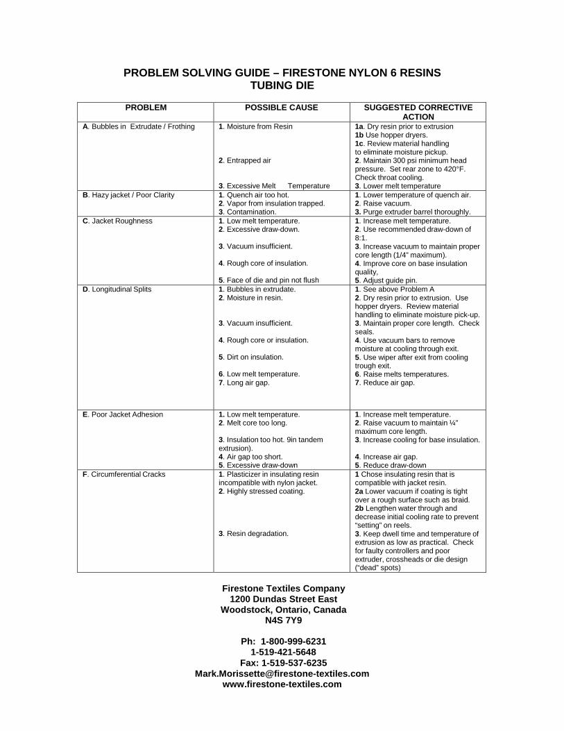
PROBLEM SOLVING GUIDE – FIRESTONE NYLON 6 RESINS TUBING DIE
PROBLEM POSSIBLE CAUSE SUGGESTED CORRECTIVE
ACTION A. Bubbles in Extrudate / Frothing 1. Moisture from Resin
2. Entrapped air
3. Excessive Melt Temperature
1a. Dry resin prior to extrusion 1b Use hopper dryers. 1c. Review material handling to eliminate moisture pickup. 2. Maintain 300 psi minimum head pressure. Set rear zone to 420°F. Check throat cooling. 3. Lower melt temperature
B. Hazy jacket / Poor Clarity 1. Quench air too hot. 2. Vapor from insulation trapped. 3. Contamination.
1. Lower temperature of quench air. 2. Raise vacuum. 3. Purge extruder barrel thoroughly.
C. Jacket Roughness 1. Low melt temperature. 2. Excessive draw-down.
3. Vacuum insufficient.
4. Rough core of insulation.
5. Face of die and pin not flush
1. Increase melt temperature. 2. Use recommended draw-down of 8:1. 3. Increase vacuum to maintain proper core length (1/4” maximum). 4. Improve core on base insulation quality, 5. Adjust guide pin.
D. Longitudinal Splits 1. Bubbles in extrudate. 2. Moisture in resin.
3. Vacuum insufficient.
4. Rough core or insulation.
5. Dirt on insulation.
6. Low melt temperature. 7. Long air gap.
1. See above Problem A 2. Dry resin prior to extrusion. Use hopper dryers. Review material handling to eliminate moisture pick-up. 3. Maintain proper core length. Check seals. 4. Use vacuum bars to remove moisture at cooling through exit. 5. Use wiper after exit from cooling trough exit. 6. Raise melts temperatures. 7. Reduce air gap.
E. Poor Jacket Adhesion 1. Low melt temperature. 2. Melt core too long.
3. Insulation too hot. 9in tandem extrusion). 4. Air gap too short. 5. Excessive draw-down
1. Increase melt temperature. 2. Raise vacuum to maintain ¼” maximum core length. 3. Increase cooling for base insulation.
4. Increase air gap. 5. Reduce draw-down
F. Circumferential Cracks 1. Plasticizer in insulating resin incompatible with nylon jacket. 2. Highly stressed coating.
3. Resin degradation.
1 Chose insulating resin that is compatible with jacket resin. 2a Lower vacuum if coating is tight over a rough surface such as braid. 2b Lengthen water through and decrease initial cooling rate to prevent “setting” on reels. 3. Keep dwell time and temperature of extrusion as low as practical. Check for faulty controllers and poor extruder, crossheads or die design (“dead” spots)
Firestone Textiles Company
1200 Dundas Street East Woodstock, Ontario, Canada
N4S 7Y9
Ph: 1-800-999-6231 1-519-421-5648
Fax: 1-519-537-6235 [email protected]
www.firestone-textiles.com