Embed Size (px)
Citation preview
WIRELESS TRANSMISSION SYSTEM FOR A RAILWAY BRIDGE
SUBJECT TO STRUCTURAL HEALTH MONITORING
Damian SALA1, Jerzy MOTYLEWSKI1,2, Przemysław KOŁAKOWSKI1,2
1Smart-Tech Centre, Institute of Fundamental Technological Research,
Polish Academy of Sciences, Warsaw, Poland, http://smart.ippt.gov.pl 2Adaptronica sp. z o.o., R&D company, Łomianki, Poland, http://www.adaptronica.pl
Jednym z prężnie rozwijających się tematów badawczych w elektronice jest bezprzewodowa
transmisja danych, na którą jest duże zapotrzebowanie w monitorowaniu stanu konstrukcji
inżynierskich. W artykule opisano nowo projektowany system bezprzewodowej transmisji danych
do monitorowania stanu technicznego mostu kolejowego.
Słowa kluczowe: bezprzewodowa transmisja danych, monitorowanie stanu konstrukcji
One of the fast-developing research topics in electronics is the wireless data transmission,
which is a highly desirable component in health monitoring of engineering structures. The paper
describes a newly-designed system of wireless data transmission for structural health monitoring
of a railway bridge.
Keywords: wireless transmission of data, structural health monitoring
1. INTRODUCTION
This paper describes a wireless transmission
system to be operating on a real bridge structure.
The investigated bridge (Fig. 1) is a single-span, 40-
meter-long, steel truss structure providing support
for a single railway track. The program of
monitoring of the bridge includes two major issues.
First, monitoring of structural health and its potential
degradation due to e.g. corrosion is planned. Second,
monitoring of railway car mass and speed is of
interest to the owner of the railway infrastructure.
The monitoring will be performed using
piezoelectric strain sensors.
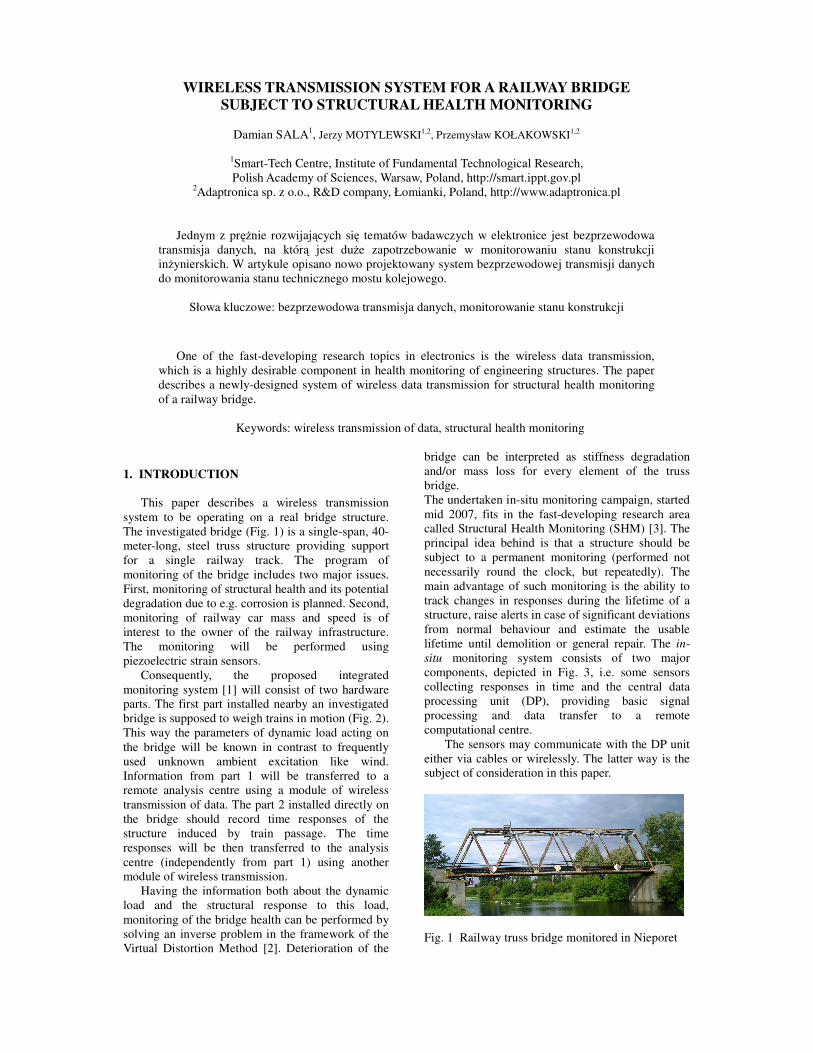
Consequently, the proposed integrated
monitoring system [1] will consist of two hardware
parts. The first part installed nearby an investigated
bridge is supposed to weigh trains in motion (Fig. 2).
This way the parameters of dynamic load acting on
the bridge will be known in contrast to frequently
used unknown ambient excitation like wind.
Information from part 1 will be transferred to a
remote analysis centre using a module of wireless
transmission of data. The part 2 installed directly on
the bridge should record time responses of the
structure induced by train passage. The time
responses will be then transferred to the analysis
centre (independently from part 1) using another
module of wireless transmission.
Having the information both about the dynamic
load and the structural response to this load,
monitoring of the bridge health can be performed by
solving an inverse problem in the framework of the
Virtual Distortion Method [2]. Deterioration of the
bridge can be interpreted as stiffness degradation
and/or mass loss for every element of the truss
bridge.
The undertaken in-situ monitoring campaign, started
mid 2007, fits in the fast-developing research area
called Structural Health Monitoring (SHM) [3]. The
principal idea behind is that a structure should be
subject to a permanent monitoring (performed not
necessarily round the clock, but repeatedly). The
main advantage of such monitoring is the ability to
track changes in responses during the lifetime of a
structure, raise alerts in case of significant deviations
from normal behaviour and estimate the usable
lifetime until demolition or general repair. The in-
situ monitoring system consists of two major
components, depicted in Fig. 3, i.e. some sensors
collecting responses in time and the central data
processing unit (DP), providing basic signal
processing and data transfer to a remote
computational centre.
The sensors may communicate with the DP unit
either via cables or wirelessly. The latter way is the
subject of consideration in this paper.
Fig. 1 Railway truss bridge monitored in Nieporet
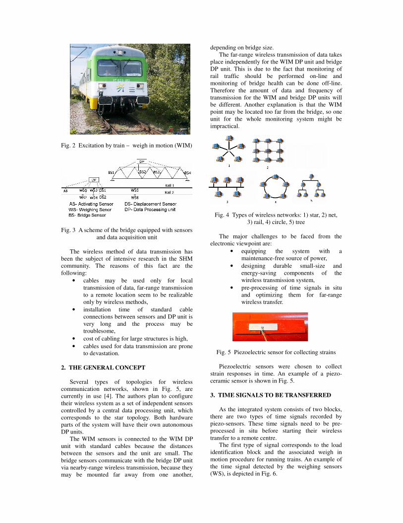
Fig. 2 Excitation by train – weigh in motion (WIM)
Fig. 3 A scheme of the bridge equipped with sensors
and data acquisition unit
The wireless method of data transmission has
been the subject of intensive research in the SHM
community. The reasons of this fact are the
following:
• cables may be used only for local
transmission of data, far-range transmission
to a remote location seem to be realizable
only by wireless methods,
• installation time of standard cable
connections between sensors and DP unit is
very long and the process may be
troublesome,
• cost of cabling for large structures is high,
• cables used for data transmission are prone
to devastation.
2. THE GENERAL CONCEPT
Several types of topologies for wireless
communication networks, shown in Fig. 5, are
currently in use [4]. The authors plan to configure
their wireless system as a set of independent sensors
controlled by a central data processing unit, which
corresponds to the star topology. Both hardware
parts of the system will have their own autonomous
DP units.
The WIM sensors is connected to the WIM DP
unit with standard cables because the distances
between the sensors and the unit are small. The
bridge sensors communicate with the bridge DP unit
via nearby-range wireless transmission, because they
may be mounted far away from one another,
depending on bridge size.
The far-range wireless transmission of data takes
place independently for the WIM DP unit and bridge
DP unit. This is due to the fact that monitoring of
rail traffic should be performed on-line and
monitoring of bridge health can be done off-line.
Therefore the amount of data and frequency of
transmission for the WIM and bridge DP units will
be different. Another explanation is that the WIM
point may be located too far from the bridge, so one
unit for the whole monitoring system might be
impractical.
Fig. 4 Types of wireless networks: 1) star, 2) net,
3) rail, 4) circle, 5) tree
The major challenges to be faced from the
electronic viewpoint are:
• equipping the system with a
maintenance-free source of power,
• designing durable small-size and
energy-saving components of the
wireless transmission system,
• pre-processing of time signals in situ
and optimizing them for far-range
wireless transfer.
Fig. 5 Piezoelectric sensor for collecting strains
Piezoelectric sensors were chosen to collect
strain responses in time. An example of a piezo-
ceramic sensor is shown in Fig. 5.
3. TIME SIGNALS TO BE TRANSFERRED
As the integrated system consists of two blocks,
there are two types of time signals recorded by
piezo-sensors. These time signals need to be pre-
processed in situ before starting their wireless
transfer to a remote centre.
The first type of signal corresponds to the load
identification block and the associated weigh in
motion procedure for running trains. An example of
the time signal detected by the weighing sensors
(WS), is depicted in Fig. 6.
The second type of signal corresponds to the
bridge health monitoring block and the associated
damage identification procedure. An example of the
time signal captured by bridge sensors (BS) is
shown in Fig. 7.
Fig. 6 Signal captured by a weighing sensor
Fig. 7 Signal captured by a bridge sensor
4. WIRELESS TRANSMISSION SYSTEM
In the authors’ opinion, the wireless system for
SHM should be characterized by a relative
simplicity, high reliability and low energy
consumption.
The complete system proposed in this paper can
be divided into two subsystems – for weighing trains
in motion and for health monitoring of the bridge.
Detailed proposition of the wireless solutions will be
focused on the latter subsystem only. The reason is
that both the nearby-range and far-range
transmission has to be considered for the bridge.
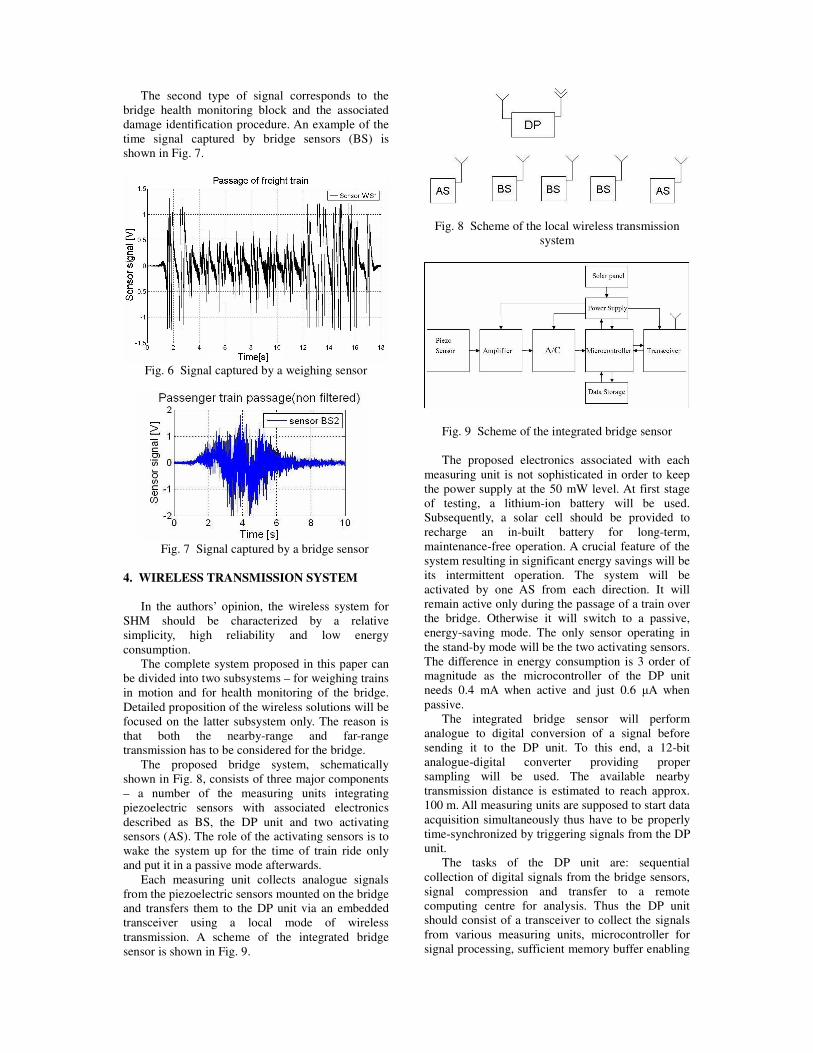
The proposed bridge system, schematically
shown in Fig. 8, consists of three major components
– a number of the measuring units integrating
piezoelectric sensors with associated electronics
described as BS, the DP unit and two activating
sensors (AS). The role of the activating sensors is to
wake the system up for the time of train ride only
and put it in a passive mode afterwards.
Each measuring unit collects analogue signals
from the piezoelectric sensors mounted on the bridge
and transfers them to the DP unit via an embedded
transceiver using a local mode of wireless
transmission. A scheme of the integrated bridge
sensor is shown in Fig. 9.
Fig. 8 Scheme of the local wireless transmission
system
Fig. 9 Scheme of the integrated bridge sensor
The proposed electronics associated with each
measuring unit is not sophisticated in order to keep
the power supply at the 50 mW level. At first stage
of testing, a lithium-ion battery will be used.
Subsequently, a solar cell should be provided to
recharge an in-built battery for long-term,
maintenance-free operation. A crucial feature of the
system resulting in significant energy savings will be
its intermittent operation. The system will be
activated by one AS from each direction. It will
remain active only during the passage of a train over
the bridge. Otherwise it will switch to a passive,
energy-saving mode. The only sensor operating in
the stand-by mode will be the two activating sensors.
The difference in energy consumption is 3 order of
magnitude as the microcontroller of the DP unit
needs 0.4 mA when active and just 0.6 µA when
passive.
The integrated bridge sensor will perform
analogue to digital conversion of a signal before
sending it to the DP unit. To this end, a 12-bit
analogue-digital converter providing proper
sampling will be used. The available nearby
transmission distance is estimated to reach approx.
100 m. All measuring units are supposed to start data
acquisition simultaneously thus have to be properly
time-synchronized by triggering signals from the DP
unit.
The tasks of the DP unit are: sequential
collection of digital signals from the bridge sensors,
signal compression and transfer to a remote
computing centre for analysis. Thus the DP unit
should consist of a transceiver to collect the signals
from various measuring units, microcontroller for
signal processing, sufficient memory buffer enabling
storage of data and additional RS-232 port for
possible in-situ acquisition. A scheme of the DP unit
is depicted in Fig. 10. Advantage of the GSM system
is taken to transfer the digital data to a remote
computational centre.
Fig. 10 Scheme of the DP unit
Several tests of the proposed system are planned,
starting from a check of the performance of a single
measuring unit, through the design of the DP unit,
finally leading to the installation of the system in
situ and its subsequent verification.
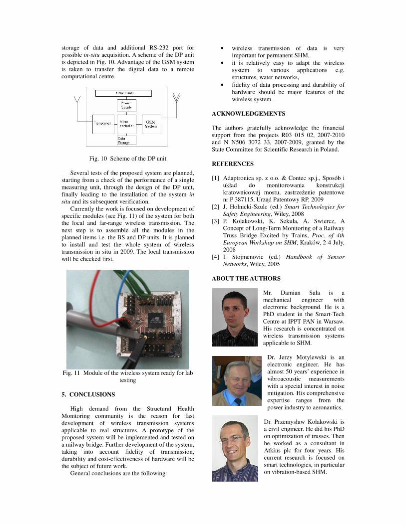
Currently the work is focused on development of
specific modules (see Fig. 11) of the system for both
the local and far-range wireless transmission. The
next step is to assemble all the modules in the
planned items i.e. the BS and DP units. It is planned
to install and test the whole system of wireless
transmission in situ in 2009. The local transmission
will be checked first.
Fig. 11 Module of the wireless system ready for lab
testing
5. CONCLUSIONS
High demand from the Structural Health
Monitoring community is the reason for fast
development of wireless transmission systems
applicable to real structures. A prototype of the
proposed system will be implemented and tested on
a railway bridge. Further development of the system,
taking into account fidelity of transmission,
durability and cost-effectiveness of hardware will be
the subject of future work.
General conclusions are the following:
• wireless transmission of data is very
important for permanent SHM,
• it is relatively easy to adapt the wireless
system to various applications e.g.
structures, water networks,
• fidelity of data processing and durability of
hardware should be major features of the
wireless system.
ACKNOWLEDGEMENTS
The authors gratefully acknowledge the financial
support from the projects R03 015 02, 2007-2010
and N N506 3072 33, 2007-2009, granted by the
State Committee for Scientific Research in Poland.
REFERENCES
[1] Adaptronica sp. z o.o. & Contec sp.j., Sposób i
układ do monitorowania konstrukcji
kratownicowej mostu, zastrzeżenie patentowe
nr P 387115, Urząd Patentowy RP, 2009
[2] J. Holnicki-Szulc (ed.) Smart Technologies for
Safety Engineering, Wiley, 2008
[3] P. Kolakowski, K. Sekula, A. Swiercz, A
Concept of Long-Term Monitoring of a Railway
Truss Bridge Excited by Trains, Proc. of 4th
European Workshop on SHM, Kraków, 2-4 July,
2008
[4] I. Stojmenovic (ed.) Handbook of Sensor
Networks, Wiley, 2005
ABOUT THE AUTHORS
Mr. Damian Sala is a
mechanical engineer with
electronic background. He is a
PhD student in the Smart-Tech
Centre at IPPT PAN in Warsaw.
His research is concentrated on
wireless transmission systems
applicable to SHM.
Dr. Jerzy Motylewski is an
electronic engineer. He has
almost 50 years’ experience in
vibroacoustic measurements
with a special interest in noise
mitigation. His comprehensive
expertise ranges from the
power industry to aeronautics.
Dr. Przemysław Kołakowski is
a civil engineer. He did his PhD
on optimization of trusses. Then
he worked as a consultant in
Atkins plc for four years. His
current research is focused on
smart technologies, in particular
on vibration-based SHM.