EPIC
Cooling The EPIC Telescope and Focal Plane
Path to CMB Pol Workshop
University of ChicagoJuly 3, 2009
Jamie Bock (JPL) Study leader
Talso Chui (JPL) Spacecraft
Jeff Raab (NGAS) 4K Cooler
Warren Holmes (JPL) Sub-K

EPIC
EPIC-ized Planck Cooling Chain
Use ~15KPulse Tube for EPIC
Sunshields Added to V-Groove Radiators
ADR Baselined
4.4K Joule-Thompson(maybe 4.4K + 1.7K Stage)
EPIC
EPIC Configuration
April 24, 2009 3
Launch Configuration
Solar Illumination and the Scan Pattern
4th shield
Deployed Configuration
•“4K” Telescope Design Includes 4th Shield•“30K” Telescope Design Omits 4th Shield

EPIC
Mechanical Design (4K Telescope Focal Plane Shown)
4K Shield(reddish)
InterceptShield(orange)
DetectorStage(orange)
Tiled Blocking Filters on Each Shield4K Telescope = 11094 Detectors30K Telescope = 2022 Detectors
Herschel-SPIRE Focal Plane
Planck

EPIC
5
Radiator Thermal Model
First Shield
Fourth Shield
SC
(c) Silver Teflon film (green)
Aluminized Kapton
Aluminized Kapton
Aluminized Kapton
Silver Teflon
Black Paint
Black Paint
Aluminized Kapton
(a)
Indium Tin Oxide for charge controlTeflonSilver with Inconel protective coatAdhesiveKaptonAluminum
Acrylic overcoat
Acrylic overcoat
Acrylic overcoat
Aluminum
AluminumKapton
(b) Doubled Aluminized Kapton film (red)

EPIC
6
Conductor Properties
0 50 100 150 200 250 300 35010
-2
10-1
100
101
102
103
T (K)
The
rmal
con
duct
ivity
k (
w/m
-K)
Gold, high disordered state
Al 6061-T6
Manganin
Red - -aluminaBlue – Effective k of strut
Teflon
HTS wire
Brass
Effective kstrut and wires
strut
i
iiieff LA
LAkk

EPIC
7
Modelling Technique
• Thermal Desktop – uses finite difference method to solve a 2D thermal equivalent electrical network.
• Uses RADCAD module of Thermal Desktop for Monte Carlo Ray Trace analysis.
– 50,000 rays per node.
• 2,900 nodes in model.
• Takes ~ 8 minutes to run on a 3.59 GHz Pentium CPU on Windows XP operating system.

EPIC
8
Model Output – steady state, no active cooling, four-shields option
T(K) Radiative Heat Transfer to
Next Stage (W)
Conductive Heat Transfer to Next
Stage (W)
Radiative Heat Transfer to Space (W)
Thermal Resistance to
next stage (K/W)1st Shield 231 69.5 3.91 16,300 29.32nd Shield 116.5 5.89 1.07 75.44 52.43rd Shield 60.39 0.685 0.264 6.00 85.84th Shield 37.75 0.0299 0.0266 0.892 323
Optical Box 29.15 0.00282 0.01213 0.0294 580Telescope 22.12 NA NA 0.0232 NA
Model summary of temperatures, thermal resistances, radiative and conductive heat transfer.
System 3D view Telescope

EPIC
9
Model Output – steady state-four-shields option
Optical Box
4th Shield
3rd Shield
2nd Shield
1st Shield
Spacecraft

EPIC
10
Spin SC at 0.5 rpm, Time Dependent Analysis
1st Shield T = 1.2 K pp
2nd Shield T = 0.3 mK pp
3rd Shield T not observable at 3 K level
Digitization noise
• Thermal isolation 4000 per stage.
• Implies 19 pico K variation at 4th shield.
EPIC
11
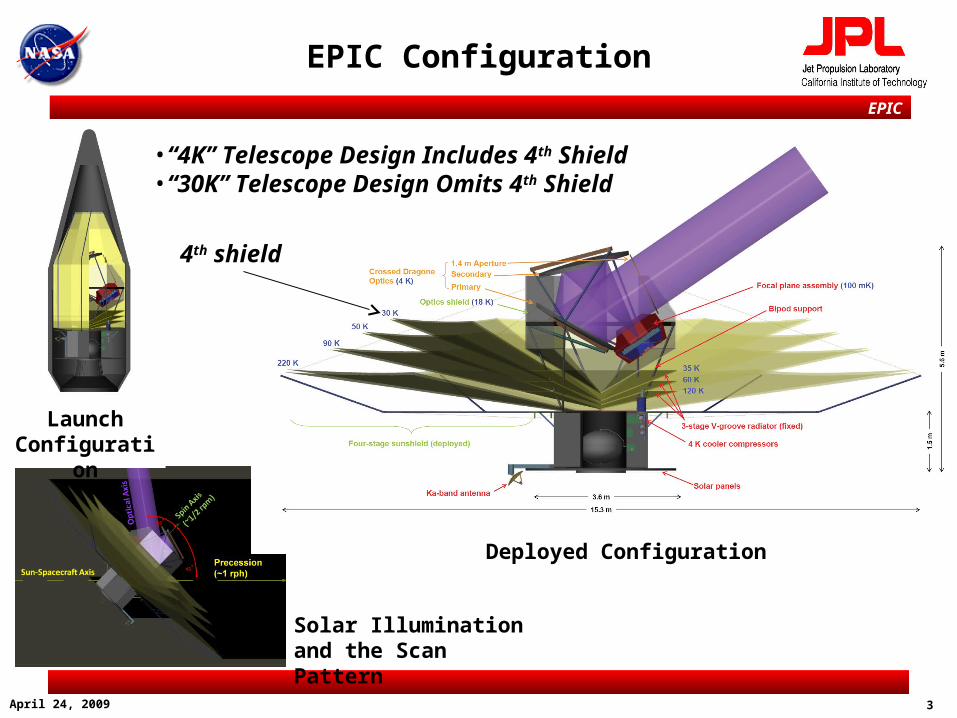
Moonshine
• Moon Shine Energy Flux
2cos dASq MoonMoon Earth
Moon
Lunar Orbit
L2 d
Scaled Position of Earth, Moon and L2. Dimensions are in units of 106 km.
S = Solar constant = 1350 W/m2
Amoon= rMoon2 = disk area of the Moon = 9.49x10⁶ km2
d = distance between L2 and the Moon = 1.54x10⁶ kmdegree90% of qMoon is infra red, 10% is visible light.
2mW/m 1.33Moonq
• At Apogee - Small Amount of Moon Shine Illuminates Back of Telescope
• Heating From Moon Is Negligible
At Apogee Moon shine touches red-purple area

EPIC
• Software Tool Assumption – Absorptivity/Emissivity Is Independent of Wavelength.
• Metal Coated Surfaces
• Colder Surface Emissivity () Always Less Than Absorptivity ()
• Software Tool Under Estimates Heat Transfer from Hot to Cold Side in V-Grooves
• The actual temperature should be 10% higher.
• The error is about the size of uncertainties in material properties.
12
“Greying” of Radiative Coatings
4Tq o
%104
1
q
q
T
T
5.0)()(
4.15.0
cold
hot
cold
hot
T
T
q
q%40or
q
q

EPIC
13
EPIC 4.4K Cooler – Extension of MIRI Cooler Design
• The approach to the Experimental Probe of Inflationary Cosmology (EPIC) cryocooler is to define low-risk hardware and software with minimal changes from flight heritage designs. This approach minimizes cost, schedule, and risk by adapting the very similar design developed for the Mid InfraRed Instrument (MIRI) on the James Webb Space Telescope (JWST) to the EPIC requirements
J - T
CCERed.15
53
Cooler Tower Assembly
(CTA)
Cooler ControlElectronics (CCE)
Cold Head Assembly (CHA)
HCC
Comp.
(PT)
RSAJ -T
CCEPrimary15
53
PT
CCERed.15
53
RSAPT
CCEPrimary15
53
JT
OMS
HX
Precooler Coldhead
MIRI
engineering
Flight
qual ’edKey
Spac
ecra
ft
JT Compressor
Precooler Environmental
Shield
R1RLDAR4 R3 R2
HEC
Comp.
Reed
Valve
Assy.
Cooler Compressor Assembly(CCA)
Bypass
De - Contamination Comp.
Reed
Valve
Assy.
Cooler Compressor Assembly(CCA)
Bypass
-
ValveValve
J - T
CCERed.15
53
Cooler Tower Assembly
(CTA)
Cooler ControlElectronics (CCE)
Cold Head Assembly (CHA)
HCC
Comp.
(PT)
J -TCCE
Primary1553
PT
CCERed.15
53
RSA
PT
CCEPrimary15
53
JT
OMS
HX
MIRI
engineering
Flight
qual ’edKey
Spac
ecra
ft
JT Compressor
R1RLDAR4 R3 R2
HEC
Precooler Environmental
Shield
Precooler Coldhead
EPIC<18K
EPIC4.4K
2X forEPIC
J-T
PT – Pulse tube JT – Joule Thompson CCE – Cryocooler Control Electronics HEC – High eff. compressor HCC – High capacity compressor RX – Recuperators
EPIC changes
De Contamination Field Joint

EPIC
14
Cryocooler Flight History and Reliability
(X) Number of Flight Units
Flight Project Electronics '98 '99 '00 '01 02 '03 '04 '05 '06
CX (2) Mini-Pulse Airs Class (2)
HTSSE (1) Stirling Custom
MTI (1) Airs Class Airs Class
HYPERION (1) Mini-Pulse Hyperion Class
SABER (1) Mini-Pulse Demo
STSS (4) Mini-Pulse Airs Class (4)
AIRS (2) Airs Class Airs Class (2)
TES (2) Airs Class Airs Class (2)
GOSAT(1) HEC Hyperion Class (1)
JAMI (2) HEC Hyperion Class (2)
OPAL (2) HEC Hyperion Class (4)
Hybrid 2 Stage (2) HEC ACE (2)
Cooler '07 '08
OCO (1) Airs Class Airs Class (1)
ARGOS host satellite failed
GOES ABI (8) HEC ACE (8)
Flight Project Electronics '98 '99 '00 '01 02 '03 '04 '05 '06
CX (2) Mini-Pulse Airs Class (2)
HTSSE (1) Stirling Custom
MTI (1) Airs Class Airs Class
HYPERION (1) Mini-Pulse Hyperion Class
SABER (1) Mini-Pulse Demo
STSS (4) Mini-Pulse Airs Class (4)
AIRS (2) Airs Class Airs Class (2)
TES (2) Airs Class Airs Class (2)
GOSAT(1) HEC Hyperion Class (1)
JAMI (2) HEC Hyperion Class (2)
HTP (2) HEC ACE (2)
In Orbit
Cooler '07 '08
OCO (1) Airs Class Airs Class (1)
ARGOS host satellite reached EOL
GOES ABI (8) HEC ACE (8)
NEWT (2) HEC ACE (2)
MIRI (1) HCC/HEC-JT 10K ACE (2)
'09
NGAS Flight Coolers Are Reliable- All performing nominally

EPIC
15
4.4K Cryocooler Cooling Loads for MIRI and EPIC Applications
• The EPIC requirements with 100% cooling margin are well with-in the capability of the MIRI cooler
MIRI EPIC
Temperature (K)
Heat Load (mW)
Temperature (K)
Heat Load (mW)
Stage 4 6.2 65 4.4 42
Stage 3 17-18 78 <18 134
Reject Temperature 313 K 300 K
Bus Power (steady state) 400 W 270 W
Bus Power (cooldown) 475 W TBD

EPIC
16
Measured JT Cooling at 4.4K using MIRI EM Cooler
• Demonstrated performance at 4.4K and anchored model used to predict the EPIC cases for “4K” and 30K optics cases
0
10
20
30
40
50
60
0 50 100 150 200 250 300 350
Heat Lift at 15K (mW)
He
at
Lif
t a
t 4
.4K
(m
W)
Measurement
anchored model
367 W measured input power to compressors
EPICMargined Load
4.4K Optics
EPICMargined Load
30K Optics
Test Facility

EPIC
17
4.4K Cooler Bus Power Estimates for Different Operating Points
• Parametric combinations of 4.4K and 15K loads versus bus power various loads for the optical bench/cavity (15K) and ADR/sensor assembly (4.4K)
0.000
0.010
0.020
0.030
0.040
0.050
0.060
0.070
100 200 300 400 500
Bus Power (W)
Lif
t at
4.4
K (
W)
0 mW intercept load, Model
100 mW intercept load, Model
200 mW intercept load, Model
300 mW intercept load, Model
Reference point

EPIC
Sub-K Cooler Method of Analysis
• Define Structure and Focal Plane Mass
– 4.4K Shield, Thermal Intercept Stage, Detector Stage
– CAD Model + Mag Shields Scaled from SPIDER Actual Mass
– Size “Magic” Ti 15-3-3-3 Struts for Launch Loads
• Compute Direct Heat Loads
– “Non Signal” Thermal IR Transmitted or Emitted by Blocking Filters
– Detector and SQUID Bias Loads
– Cable Heat Leak (SPIRE-Like Cables, Nb-Ti Wires)
• Compute Performance for Different Coolers
– ADR + 4.4K Cryocooler
– Planck Like Closed Cycle Dilution + 1.7K + 4.4K Cryocooler
– Parallel 3He + ADR + 1.7K + 4.4K Cryocooler Stage
• Gas Gap heat Switches >1K, Superconducting Heat Switches <1K
• Vandium Permendur Flux Return Magnet Shield

EPIC
Adiabatic Demagnetization Refrigerator (ADR)
– ‘On State’ During Magnetization (AB) Reject Heat at High T
– ‘Off State’ During Adiabatic Demag (BC)
– Isothermal Demagnetization (CD) Absorb Heat at Low T
– Warm Up (AD) and Repeat Cycle A-B-C-D
EPIC
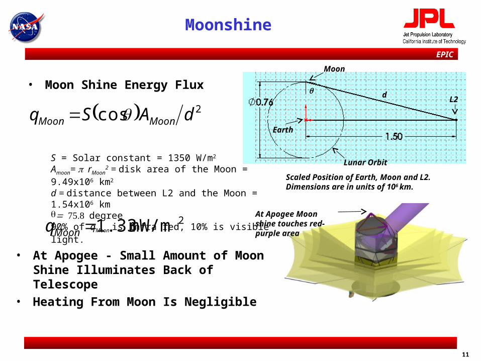
Continuous Cooling (Serial Method Shown)
•Paired ADRs Alternate Cycling to Maintain Constant Temperature at 1200mK and 100mK Stages
•1200mK Is Heat Intercept Stage•100mK Is Detector Stage
•~30% Swing in Total Power to Cryocooler•4 Heat Switches

EPIC
Continuous Magnet Cycling
0.0
0.5
1.0
1.5
2.0
2.5
3.0
3.5
4.0
4.5
5.0
0 5 10 15 20 25
Time (hours)
Po
we
r to
1.7
K (
mW
)
0
1
2
3
4
5
6
7
8
9
10
Mag
net
Cu
rren
t (A
)
Intercept AMagnet
Intercept BMagnet
Power to 1.7K
Duty Cycle ~60%Balances Power Load to 1.7KCryocooler
Cryocooler
Cry
oco
ole
r
Serial Continuous ADRBlack Curves Only
EPIC
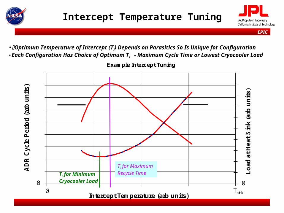
Intercept Temperature Tuning
Lo
ad a
t H
eat
Sin
k (a
rb u
nit
s)
AD
R C
ycle
Per
iod
(ar
b u
nit
s)
Intercept Temperature (arb units)
Example Intercept Tuning
00 0
Tsink
Ti for Minimum Cryocooler Load
Ti for Maximum Recycle Time
•Optimum Temperature of Intercept (Ti) Depends on Parasitics So Is Unique for Configuration•Each Configuration Has Choice of Optimum Ti - Maximum Cycle Time or Lowest Cryocooler Load

EPIC
• Cooler to Focal Plane Heat Strap Design Important Regardless of Cooler
• Heat Strap Mass Fully Constrained
– m=ljAs=Pd ld2/(0f Td
2)
– Pdand Td Fixed by Detector Requirements and Instrument Design
– For a Metallic Heat Strap Pd Td2 = Constant
– With No Intercept Stage Heat Straps >7kg
• Lightweighting of Isothermal Detector Holders a Special Job for EPIC
– Ground Based Strategy Is “Just Add More Copper”
– In Plane Thermal Spreaders Are ~10kg for SCUBA II
– Space Designs Need Optimization
Heat Straps and Detector Holder Thermal Engineering
EPIC
0
5
10
15
20
25
0 1 2 3 4 5 6
CB
E M
ass
(kg
)
Hold Time (hr)
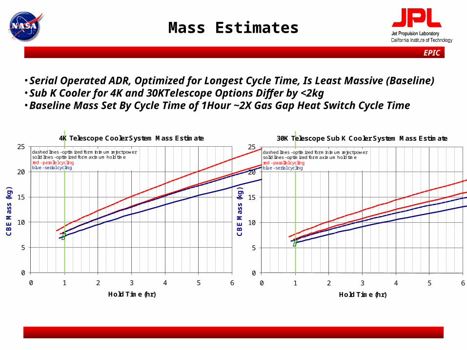
4K Telescope Cooler System Mass Estimate
dashed lines - optimized for minimum reject powersolid lines - optimized for maximum hold timedashed lines - optimized for minimum reject powersolid lines - optimized for maximum hold timered - parallel cyclingblue - serial cycling
0
5
10
15
20
25
0 1 2 3 4 5 6
CB
E M
ass
(kg
)
Hold Time (hr)
30K Telescope Sub K Cooler System Mass Estimate
dashed lines - optimized for minimum reject powersolid lines - optimized for maximum hold timedashed lines - optimized for minimum reject powersolid lines - optimized for maximum hold timered - parallel cyclingblue - serial cycling
Mass Estimates
•Serial Operated ADR, Optimized for Longest Cycle Time, Is Least Massive (Baseline)•Sub K Cooler for 4K and 30KTelescope Options Differ by <2kg•Baseline Mass Set By Cycle Time of 1Hour ~2X Gas Gap Heat Switch Cycle Time

EPIC
Heat Load Table
Units 4K Telescope 30K Telescope
Detector System Power W 1.76 0.34
IR Loading (Detector/Intercept) W 2.8/3.0 2.2/6.4
Detector Stage Heat Lift W 8.1 5.0
Intercept Temperature K 1.03 0.996
Intercept Stage Heat Lift W 205 142
Heat Strap Mass kg 1.1 0.71
ADR System Mass kg 7.2 6.0
ADR Cooler Load at 4.4K mW 5.5 4.3
•Serial Cycled CADR Used for Mass Estimate

EPIC
Planck Dilution Principle of Operation
-4He flow Sets Cooling at 100mK-P = 33 n4 f(T) T2 (mW/(mmol/sec))-f~6.8% Saturation of 3He in 4He-Prefactor 34 In Ideal Dilution Is 82
-Undiluted 3He flow Provides Additional Cooling ofParasitic Loads Upto Tricritical Point ~860mKP~10-15microW As Pure 3He DropletsDissolve in 4He Rich Phase
n4
n3
JT Expansion ProvidesMore Additional CoolingPlanck JT at <1.4K~200-300mircoW + Parasitics
10-20bar Input
~ 0bar Output
0.097K
EPIC
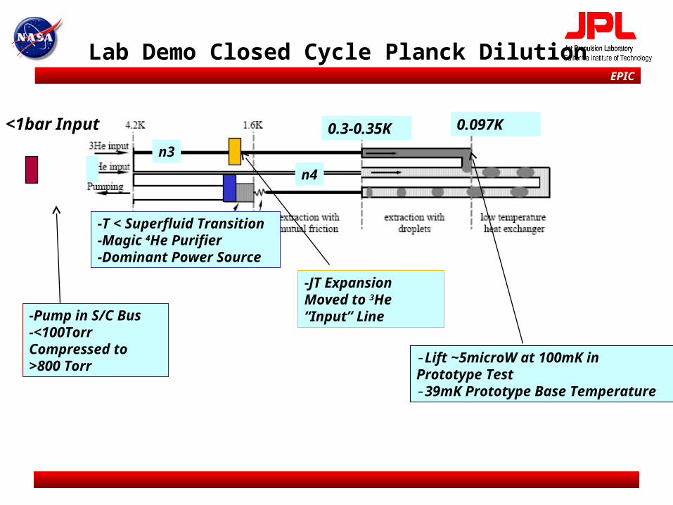
Lab Demo Closed Cycle Planck Dilution
n4
n3
-T < Superfluid Transition-Magic 4He Purifier-Dominant Power Source
<1bar Input 0.097K
-Pump in S/C Bus-<100Torr Compressed to >800 Torr
-JT Expansion Moved to 3He “Input” Line
0.3-0.35K
-Lift ~5microW at 100mK in Prototype Test-39mK Prototype Base Temperature

EPIC
Continuous Cooling (3He + ADR Parallel Only)
•Replace “High Temperature ADR with Herschel-Like 3He Sorption Cooler•Feasible if Cryocooler Stage at 1.7K•Used Cycling Powers from L. Duband, et al Cryogenics (2006)•Near Constant Power to Cryocooler•8 Heat Switches•20mW Lift Needed at 1.7K•~ Mass of ADR/ ADR System•Removes “High Field” ADRs •Single Shot Option?
3He 3He
300mK
3He 3He
300mK

EPIC
Sub-K Cooler - Conclusions
Sized Different Coolers Technologies For EPIC ADR Mass and Power Performance Within Prototype Capabilities Closed Cycle Planck Dilution Cooler Feasible
Units ADR/ADR Closed Planck Dilution
3He + ADR
Cryocooler Temeprature (K) 4.4 or 1.7 1.7 1.7
Cryogenic Mass kg 9.5 or < 9.5 ~5 <9.5
Cryogenic Magnetic Field yes no yes
Heat Switches 4 0 8Heat Load to Cryocooler mW 8 or ~3 <10 >20
Cryogenic Fault Tolerance Partial Ice Plug Heater Partial
Warm Electronics – Cooler Operation Only
W 20 150-200 12
EPIC
30
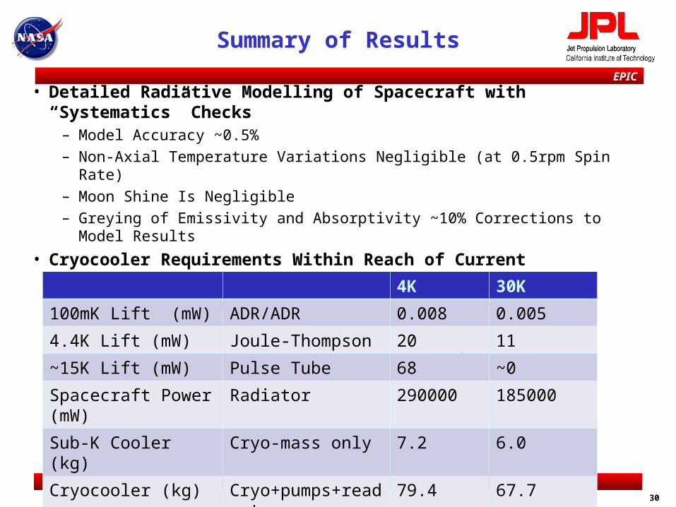
Summary of Results
• Detailed Radiative Modelling of Spacecraft with “Systematics” Checks– Model Accuracy ~0.5%
– Non-Axial Temperature Variations Negligible (at 0.5rpm Spin Rate)
– Moon Shine Is Negligible
– Greying of Emissivity and Absorptivity ~10% Corrections to Model Results
• Cryocooler Requirements Within Reach of Current Technology
– Characterizations Performed at 4.4K on ‘Flight Like Cooler’– 4.4K Cooler Based on Current MIRI Cooler (for James Webb Space Telescope)
4K 30K
100mK Lift (mW) ADR/ADR 0.008 0.005
4.4K Lift (mW) Joule-Thompson 20 11
~15K Lift (mW) Pulse Tube 68 ~0
Spacecraft Power (mW) Radiator 290000 185000
Sub-K Cooler (kg) Cryo-mass only 7.2 6.0
Cryocooler (kg) Cryo+pumps+readout 79.4 67.7

EPIC
Planck Launch
PLANCK is now a "stellar object" of an estimated magnitude 18.5 in theOphiuchus constellation.
EPIC
32
Backups

EPIC
33
Optical Properties
0 50 100 150 200 250 3000.01
0.015
0.02
0.025
0.03
0.035
0.04
0.045
0.05
0.055
0.06
T (K)
Em
issi
vity
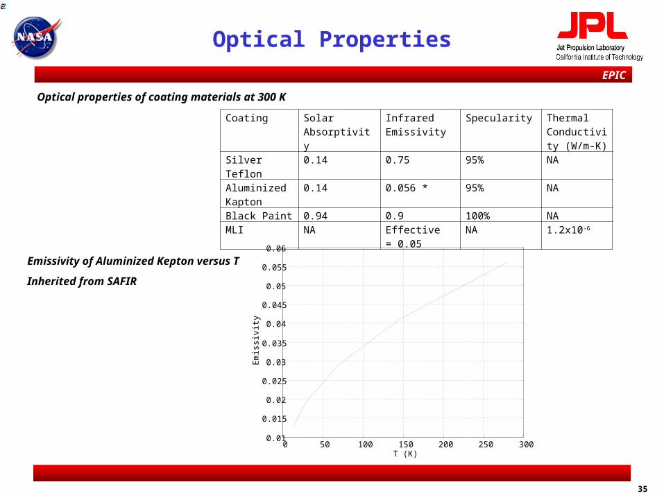
Emissivity of Aluminized Kepton versus T
Inherited from SAFIR
Coating Solar Absorptivity
Infrared Emissivity
Specularity Thermal Conductivity (W/m-K)
Silver Teflon 0.14 0.75 95% NAAluminized Kapton
0.14 0.056 * 95% NA
Black Paint 0.94 0.9 100% NAMLI NA Effective = 0.05 NA 1.2x10⁻⁶
Optical properties of coating materials at 300 K

EPIC
34
EPIC Cryocooler Properties Summary
Instrument Capabilities4.4K Optics
Capabilities30K Optics
Mass (Best Estimate)Cooler Assembly (JT/ PT Pre-cooler)Electronics (JT/Pre-cooler/Switch box) Total
(Kg)49.2 30.279.4
(Kg)49.2 17.867.0
Nominal Operating ConditionCooling Load @ 4.4KHeat Reject TemperatureBus Power at steady statePeak cool down power
42mW3000K270W
TBD W
22mW3000K165W
TBD W
Operating Temperature Range (PT and JT coolers) -20 to 50oC
Non-operating Temperature Range (PT and JT coolers) -40 to 70oC
Operating Temperature Range (CCE) -20 to 60oC
Non-operating Temperature Range (CCE) -35 to 75oC
Launch Vibration (PT and JT coolers) 14.2 Grms, 1 min
Launch Vibration (CCE) 14.2 Grms, 1 min
Launch Vibration JT cooler 18K to 4.4K component 25.8 Grms, 1 min
Bus Voltage Range 21V to 42V
Ripple Current 100 dB micro amps
Communication Protocol RS422/1553B
Lifetime >10 years
EPIC
35
Optical Properties
0 50 100 150 200 250 3000.01
0.015
0.02
0.025
0.03
0.035
0.04
0.045
0.05
0.055
0.06
T (K)
Em
issi
vity
Emissivity of Aluminized Kepton versus T
Inherited from SAFIR
Coating Solar Absorptivity
Infrared Emissivity
Specularity Thermal Conductivity (W/m-K)
Silver Teflon 0.14 0.75 95% NAAluminized Kapton
0.14 0.056 * 95% NA
Black Paint 0.94 0.9 100% NAMLI NA Effective = 0.05 NA 1.2x10⁻⁶
Optical properties of coating materials at 300 K

EPIC
ADR Heat Load Breakdown
•Serial Cycled CADR4K - TDM 30K - TDM
Detector Stage Loads (in W)
Telescope IR 2.8 2.2
Thermal IR 0 0
Heat Switch 2.1 1.8
Struts 0.91 0.56
Wires 0.43 0.1
Intercept Stage Loads (in W)
Optimum Temperature 1.03 0.996
Telescope IR 3 6.4
Thermal IR 72 35
Heat Switch 57 58
Struts 60 41
Wires 16 4

EPIC
Heat Load Table
Units 4K Telescope 30K Telescope Planck
Intercept Temperature mK 145 180 ~300
Detector Stage Dissipation W 4.6 2.5 <0.1(temp reg)
dn3/dt mole/s 15 9.7 6.7
dn4/dt mole/s 197 110 20
Cooling at 1.7 K mW 4.7 2.6 -0.2
3He per year if open cycle ℓ(STP) 10550 6870 4730
•Cryogenic Mass ~ 5kg Less Than ADR System•Required Heat Lift Not Far from Prototype Demo•No Heat Switches – 100mK Lift Is Lower•No Magnets or Magnet Leads•Requires Warm Pump (Like SPICA and MIRI JT Cooling Stages

EPIC
Generic ADR Cooler Sizing
• Compute Heat Loads Fixed as Driven by Science Goals
• Gas Gap Heat Switch for Intercept Stage
– Off State from SS Canister
– On State <50mW/K (JPL Design)
– 60% Duty Cycle for Continuous
• Superconducting Heat Switches for Detector Stage
– Switch Design Based on Mueller et al Rev Sci Inst (49) 515 (1978)
– On State Fixed for 1% Gradient at Operating Point
– Off State Phonon Conduction ~T3
• Mueller Used Al – Which Won’t Work for T>~200mK
• Use V or “Switching Ratio” ~500 Used in Model
• Pb Switching Ratio ~100 Backup, But Would Lower Ti (Heer, et al, Rev. Sci. Inst. 25, 1088 (1954)
• Maximum Field ~2.2Tesla at 6.5Amps (“Easy” to Achieve B/I Ratio)
• Flux Return Shield with Soft Ferromagnetic Material
Recommended