PARAMAX 9000
Nr. 999345
06/2009
Getriebe und GetriebemotorenReducer & Drive Units
Betriebsanleitung
Operation Manual
PARAMAX 9000 Betriebsanleitung
1E-Mail: [email protected]
www.sumitomodriveeurope.comTel. +49 (0) 8136 66 0Cyclostraße 92
85229 Markt Indersdorf PX_DEU_ENG_06_2009_999345
Copyright 2009 Alle Rechte vorbehalten
Nachdruck, auch auszugsweise, ist nur mit ausdrücklicher Genehmigung von Sumitomo gestattet.
Die Angaben in dieser Einbau- und Betriebsanleitung wurden mit größter Sorgfalt auf ihre Richtigkeit geprüft.
Trotzdem kann für eventuelle fehlerhafte oder unvollständige Angaben keine Haftung übernommen werden.
Technische Änderungen vorbehalten.
1. Allgemeine Hinweise 2
2. Hinweise zur Sicherheit 3
2.1 Sicherheitshinweise zum Betrieb der Getriebe bzw.
der Getriebemotoren 3
3. Hinweise zum Transport und Inspektion bei Anlieferung 4
3.1 Typenschilder 5
3.2 Nomenklatur 6
4. Einbau des PARAMAX-Getriebes/Getriebemotors 7
4.1 Notwendige Hilfsmittel 7
4.2 Aufstellung 7
4.3 Aufstellungswinkel 8
4.4 Aufstellung PARAMAX mit Lüfter (Parallelwelle) 9
5. Einsatzbereich 10
6. Verbindung mit anderen Maschinen 10
6.1 Anbau eines Verbindungselements 11
6.2 Hohlwelle 12
6.2.1 Montage mit Schrumpfscheibe 12
6.2.1.1 Demontage mit Schrumpfscheibe 13
6.2.2 Passfederverbindung 13
6.2.3 Drehmomentstütze 15
6.2.4 Hohlwellenabmessungen (Ausführung mit Schrumpfscheibe) 15
6.2.5 Hohlwellenabmessungen (mit Passfedernut) 16
7. Elektrische Installation 17
7.1 Sicherheitshinweise 17
7.2 Messen des Isolationswiderstands 18
7.3 Schutzanordnung 18
7.4 Motoranschluss 19
8. Inbetriebnahme 20
9. Tägliche Inspektion und Wartung 21
9.1 Inspektionsintervalle 22
9.2 Hinweise zur Schmierung 23
9.3 Schmierstoff Erstbefüllung, Nachfüllung und Wechsel 24
9.4 Wartung der Motorlager 29
10. Demontage / Montage 31
10.1 Demontage/Montage von Getriebe/Motor 32
11. Problembehandlung 32
12. Schnittzeichnungen 33
12.1 Schnittzeichnungen PARAMAX Getriebemotor 33
12.2 Schnittzeichnungen PARAMAX Getriebe 34
12.3 Schnittzeichnungen Motor 35
13. Lage Öleinfüllstutzen und Ablassschrauben 36
14 Besondere Hinweise für ATEX zugelassene
PARAMAX Getriebe und Getriebemotoren 37
14.1 Sicherheitshinweise zum Einsatz im ATEX Bereich 37
14.2 Checkliste für ATEX zugelassene Getriebe und
Getriebemotoren vor Inbetriebnahme 38
14.3. Betrieb im Explosionsbereich ATEX 39
15. EG – Maschinenrichtlinie 39
Inhaltsverzeichnis Seite

PARAMAX 9000 Betriebsanleitung
E-Mail: [email protected]
www.sumitomodriveeurope.com Tel. +49 (0) 8136 66 0Cyclostraße 92
85229 Markt Indersdorf2 PX_DEU_ENG_06_2009_999345
1. Allgemeine Hinweise
Bitte beachten Sie in dieser Dokumentation unbedingt die folgenden Sicherheitshinweise!
Gefahr durch Elektrizität
Eine falsche Anwendung der Maschine kann zu Körperschäden, ernsthaften Verletzungen und/ oder
lebensgefährlichen Situationen führen.
Gefahr
Eine falsche Anwendung der Maschine kann zu Körperschäden, ernsthaften Verletzungen und/ oder
lebensgefährlichen Situationen führen.
Gefährliche Situation
Leichte Verletzungen können die Folge sein.
Schädliche Situation
Schäden am Antrieb oder der Umgebung können die Folge sein.
Hilfreiche Informationen
Entsorgung
Bitte achten Sie auf die geltenden Bestimmungen.
Wichtige Hinweise zum Explosionsschutz
Information gilt für PARAMAX Getriebemotor
Information gilt für PARAMAX Getriebe
2. Hinweise zur Sicherheit
Lesen Sie vor der Arbeit mit der Maschine (Montage, Betrieb, Wartung, Inspektion, usw.) diese Betriebs-
anleitung aufmerksam durch, so dass Sie eine genaue Kenntnis über die richtige Bedienung des
PARAMAX, die anzuwendenden Sicherheitsbestimmungen und die zu beachtenden Warnhinweise ha-
ben. Bewahren Sie diese Anleitung bei der Maschine auf, so dass Sie bei Bedarf jederzeit nachschlagen
können.
Transport, Montage, Schmierung, Betrieb, Wartung und Inspektion dürfen nur durch ausgebildetes
technisches Fachpersonal durchgeführt werden; andernfalls besteht die Gefahr von Verletzungen oder
Schäden an der Maschine.
Niemals in sich bewegende Teile fassen und Fremdkörper von diesen Teilen fernhalten; andernfalls
besteht die Gefahr von Verletzungen oder Schäden an der Maschine.
Bei Wartungs- und Montagearbeiten ist die Getriebeanlage außer Betrieb zu setzen und von der
Stromzufuhr abzuklemmen.
Die Anlage darf nur für den vorgesehenen Verwendungszweck eingesetzt werden; andernfalls besteht
die Gefahr von Verletzungen oder Schäden an der Maschine.
Ersatzteile
Verwenden Sie nur Original Ersatzteile. Bei der Verwendung von nicht zugelassenen Ersatzteilen erlischt
jede Gewährleistung.

PARAMAX 9000 Betriebsanleitung
3E-Mail: [email protected]
www.sumitomodriveeurope.comTel. +49 (0) 8136 66 0Cyclostraße 92
85229 Markt Indersdorf PX_DEU_ENG_06_2009_999345
2.1 Sicherheitshinweise zum Betrieb der Getriebe bzw. der Getriebemotoren
Ein am Getriebe angeschlossener Antriebsmotor darf nur nach Sicherstellung der Übereinstimmung der
Angaben auf dem Typenschild mit den vorliegenden Dokumentationen (Zeichnungen, Stücklisten, usw.)
in Betrieb genommen werden.
- Der Antrieb darf keine Beschädigungen aufweisen
- Die vorgesehenen Schmierstoffe müssen entsprechend der Umgebungsbedingungen passen
und ggf. bereitgestellt werden.
Ein am Getriebe angeschlossener Motor darf nur am Frequenzumrichter betrieben werden, wenn die
Angaben auf dem Typenschild des Getriebes eingehalten werden! Die Getriebe sind für gewerbliche
Anlagen bestimmt und dürfen nur entsprechend den Angaben der technischen Dokumentation und
den Angaben auf dem Typenschild verwendet werden. Sie entsprechen den gültigen Normen und Vor-
schriften und erfüllen die Forderungen der Richtlinie 94/9EG.
Weitere wichtige Hinweise finden sie dazu in Kapitel 7.1
PARAMAX 9000 Betriebsanleitung
E-Mail: [email protected]
www.sumitomodriveeurope.com Tel. +49 (0) 8136 66 0Cyclostraße 92
85229 Markt Indersdorf4 PX_DEU_ENG_06_2009_999345
3. Hinweise zum Transport und Inspektion bei Anlieferung
Stellen Sie sich nie unter eine an einem Kran oder einer ähnlichen Hebevorrichtung aufgehängte
Einheit; es besteht die Gefahr von schweren oder tödlichen Verletzungen.
Einheit so auspacken, dass sie mit der richtigen Seite nach oben liegt; ansonsten besteht
Verletzungsgefahr.
Darauf achten, den Getriebemotor/das Getriebe nicht fallen zu lassen.
Auf jeden Fall vorhandene Ringbolzen oder Bohrungen zum Aufhängen verwenden. Es dürfen nur
zweckmäßige und ausreichend dimensionierte Seilschlingen, die in die ggf. vorhandenen
Ringschrauben eingehängt oder um die Flanschverbindungen gelegt werden, verwendet werden. Ein-
geschraubte Ringschrauben sind nur für das Gewicht des Antriebs ausgelegt. Es dürfen keine
zusätzlichen Lasten angehängt werden.
Generell gilt: Nicht die Zentrierbohrungen an den Wellenenden benutzen, um das Getriebe mittels
Ringschrauben etc. aufzuheben. Lagerschäden können die Folge sein.
Nach der Montage des PARAMAX Getriebemotors bzw. PARAMAX Getriebes an der Anlage darf die
gesamte Maschine keinesfalls am Aufhänghaken bzw. -bohrungen angehoben werden; dies kann zu
Verletzungen oder Beschädigungen der Ausrüstung bzw. der Hebevorrichtung führen.
Vor dem Hebevorgang ist das Gewicht des PARAMAX-Getriebemotors bzw. PARAMAX-Getriebes anhand
der Angaben auf/in der Verpackung, der mitgelieferten Zeichnung, des Katalog etc. zu prüfen. Keine
Einheiten anheben, deren Gewicht die Maximalbelastung des Krans oder der verwendeten Hebevor-
richtung überschreiten; dies kann zu Verletzungen oder Schäden an der Ausrüstung bzw. der
Hebevorrichtung führen.
1. die Lieferung der Bestellung entspricht (siehe auch Beschreibungen auf dem Typenschild).
Sollten irgendwelche Zweifel darüber bestehen, ob die Lieferung Ihrer Bestellung entspricht, ist eine
Vertretung, ein Händler oder ein Servicebüro vor Ort zu kontaktieren.
2. Teile während des Transports beschädigt wurden. Eventuelle Transportschäden müssen sofort
dem Transportunternehmen mitgeteilt werden. Wenn angenommen werden muss, dass ein Trans-
portschaden den ordnungsgemäßen Betrieb einschränkt, muss die Inbetriebnahme ausgeschlossen
werden.
Nach Anlieferung ist zu prüfen, ob:
Sumitomo (SHI) Cyclo Drive Germany GmbH
PARAMAX 9000 Betriebsanleitung
5E-Mail: [email protected]
www.sumitomodriveeurope.comTel. +49 (0) 8136 66 0Cyclostraße 92
85229 Markt Indersdorf PX_DEU_ENG_06_2009_999345
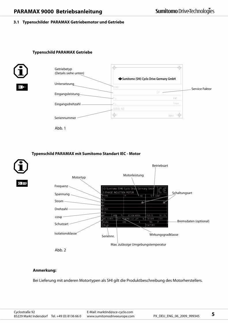
3.1 Typenschilder PARAMAX Getriebemotor und Getriebe
Typenschild PARAMAX mit Sumitomo Standart IEC - Motor
Typenschild PARAMAX Getriebe
Abb. 2
Anmerkung:
Bei Lieferung mit anderen Motortypen als SHI gilt die Produktbeschreibung des Motorherstellers.
Getriebetyp
(Details siehe unten)
Untersetzung
Eingangsleistung
Eingangsdrehzahl
Seriennummer
Abb. 1
Service Faktor
Motortyp
Frequenz
Spannung
Motorleistung
Drehzahl
cosφ
Bremsdaten (optional)
Seriennr.
Schaltungsart
Betriebsart
Strom
Schutzart
Max. zulässige Umgebungstemperatur
Isolationsklasse Wirkungsgradklasse
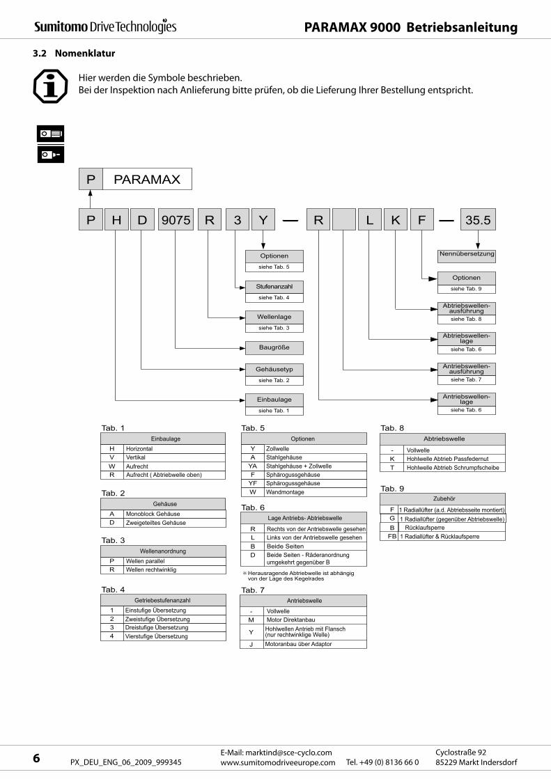
P P
P PARAMAX
H 9075 D R 3 Y
siehe Tab. 5
Stufenanzahl
siehe Tab. 4
Wellenlage
siehe Tab. 3
Baugröße
Gehäusetyp
siehe Tab. 2
Einbaulage
siehe Tab. 1
Optionen
Optionen
siehe Tab. 9
Nennübersetzung
Abtriebswellen- ausführung siehe Tab. 8
Abtriebswellen- lage
siehe Tab. 6
Antriebswellen- ausführung siehe Tab. 7
Antriebswellen- lage
siehe Tab. 6
R L K F 35.5
Einbaulage H Horizontal V Vertikal
R Aufrecht ( Abtriebwelle oben)W Aufrecht
Tab. 1 Tab. 5 Tab. 8
Tab. 9
Tab. 6
Tab. 7
Optionen
Y Zollwelle A Stahlgehäuse
YA
- K T
F G B
FB
Stahlgehäuse + Zollwelle
Vollwelle Hohlwelle Abtrieb Passfedernut Hohlwelle Abtrieb Schrumpfscheibe
F
R L B D
- M
J
Y
Sphärogussgehäuse YF Sphärogussgehäuse W Wandmontage
Gehäuse A Monoblock Gehäuse D Zweigeteiltes Gehäuse
Tab. 2
Wellenanordnung P Wellen parallel R Wellen rechtwinklig
Tab. 3
Getriebestufenanzahl 1 Einstufige Übersetzung 2 Zweistufige Übersetzung 3 Dreistufige Übersetzung
4 Vierstufige Übersetzung
Tab. 4
Rücklaufsperre
1 Radiallüfter (a.d. Abtriebsseite montiert) 1 Radiallüfter (gegenüber Abtriebswelle)
Motor Direktanbau
Motoranbau über Adaptor
Hohlwellen Antrieb mit Flansch (nur rechtwinklige Welle)
1 Radiallüfter & Rücklaufsperre
Lage Antriebs- Abtriebswelle
Antriebswelle
Rechts von der Antriebswelle gesehen Links von der Antriebswelle gesehen Beide Seiten
Vollwelle
Beide Seiten - Räderanordnung umgekehrt gegenüber B
Herausragende Abtriebwelle ist abhängig von der Lage des Kegelrades
Abtriebswelle
Zubehör
PARAMAX 9000 Betriebsanleitung
E-Mail: [email protected]
www.sumitomodriveeurope.com Tel. +49 (0) 8136 66 0Cyclostraße 92
85229 Markt Indersdorf6 PX_DEU_ENG_06_2009_999345
Hier werden die Symbole beschrieben.
Bei der Inspektion nach Anlieferung bitte prüfen, ob die Lieferung Ihrer Bestellung entspricht.
3.2 Nomenklatur
PARAMAX 9000 Betriebsanleitung
7E-Mail: [email protected]
www.sumitomodriveeurope.comTel. +49 (0) 8136 66 0Cyclostraße 92
85229 Markt Indersdorf PX_DEU_ENG_06_2009_999345
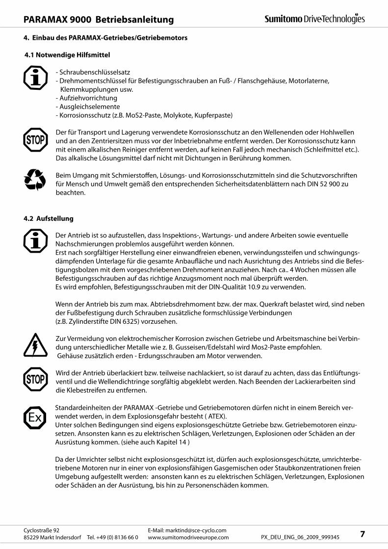
4.1 Notwendige Hilfsmittel
- Schraubenschlüsselsatz
- Drehmomentschlüssel für Befestigungsschrauben an Fuß- / Flanschgehäuse, Motorlaterne,
Klemmkupplungen usw.
- Aufziehvorrichtung
- Ausgleichselemente
- Korrosionsschutz (z.B. MoS2-Paste, Molykote, Kupferpaste)
Der für Transport und Lagerung verwendete Korrosionsschutz an den Wellenenden oder Hohlwellen
und an den Zentriersitzen muss vor der Inbetriebnahme entfernt werden. Der Korrosionsschutz kann
mit einem alkalischen Reiniger entfernt werden, auf keinen Fall jedoch mechanisch (Schleifmittel etc.).
Das alkalische Lösungsmittel darf nicht mit Dichtungen in Berührung kommen.
Beim Umgang mit Schmierstoffen, Lösungs- und Korrosionsschutzmitteln sind die Schutzvorschriften
für Mensch und Umwelt gemäß den entsprechenden Sicherheitsdatenblättern nach DIN 52 900 zu
beachten.
4.2 Aufstellung
Der Antrieb ist so aufzustellen, dass Inspektions-, Wartungs- und andere Arbeiten sowie eventuelle
Nachschmierungen problemlos ausgeführt werden können.
Erst nach sorgfältiger Herstellung einer einwandfreien ebenen, verwindungssteifen und schwingungs-
dämpfenden Unterlage für die gesamte Anbaufläche und nach Ausrichtung des Antriebs sind die Befes-
tigungsbolzen mit dem vorgeschriebenen Drehmoment anzuziehen. Nach ca.. 4 Wochen müssen alle
Befestigungsschrauben auf das richtige Anzugsmoment noch mal überprüft werden.
Es wird empfohlen, Befestigungsschrauben mit der DIN-Qualität 10.9 zu verwenden.
Wenn der Antrieb bis zum max. Abtriebsdrehmoment bzw. der max. Querkraft belastet wird, sind neben
der Fußbefestigung durch Schrauben zusätzliche formschlüssige Verbindungen
(z.B. Zylinderstifte DIN 6325) vorzusehen.
Zur Vermeidung von elektrochemischer Korrosion zwischen Getriebe und Arbeitsmaschine bei Verbin-
dung unterschiedlicher Metalle wie z. B. Gusseisen/Edelstahl wird Mos2-Paste empfohlen.
Gehäuse zusätzlich erden - Erdungsschrauben am Motor verwenden.
Wird der Antrieb überlackiert bzw. teilweise nachlackiert, so ist darauf zu achten, dass das Entlüftungs-
ventil und die Wellendichtringe sorgfältig abgeklebt werden. Nach Beenden der Lackierarbeiten sind
die Klebestreifen zu entfernen.
4. Einbau des PARAMAX-Getriebes/Getriebemotors
Standardeinheiten der PARAMAX -Getriebe und Getriebemotoren dürfen nicht in einem Bereich ver-
wendet werden, in dem Explosionsgefahr besteht ( ATEX).
Unter solchen Bedingungen sind eigens explosionsgeschützte Getriebe bzw. Getriebemotoren einzu-
setzen. Ansonsten kann es zu elektrischen Schlägen, Verletzungen, Explosionen oder Schäden an der
Ausrüstung kommen. (siehe auch Kapitel 14 )
Da der Umrichter selbst nicht explosionsgeschützt ist, dürfen auch explosionsgeschützte, umrichterbe-
triebene Motoren nur in einer von explosionsfähigen Gasgemischen oder Staubkonzentrationen freien
Umgebung aufgestellt werden: ansonsten kann es zu elektrischen Schlägen, Verletzungen, Explosionen
oder Schäden an der Ausrüstung, bis hin zu Personenschäden kommen.
10 0.3
PARAMAX 9000 Betriebsanleitung
E-Mail: [email protected]
www.sumitomodriveeurope.com Tel. +49 (0) 8136 66 0Cyclostraße 92
85229 Markt Indersdorf8 PX_DEU_ENG_06_2009_999345
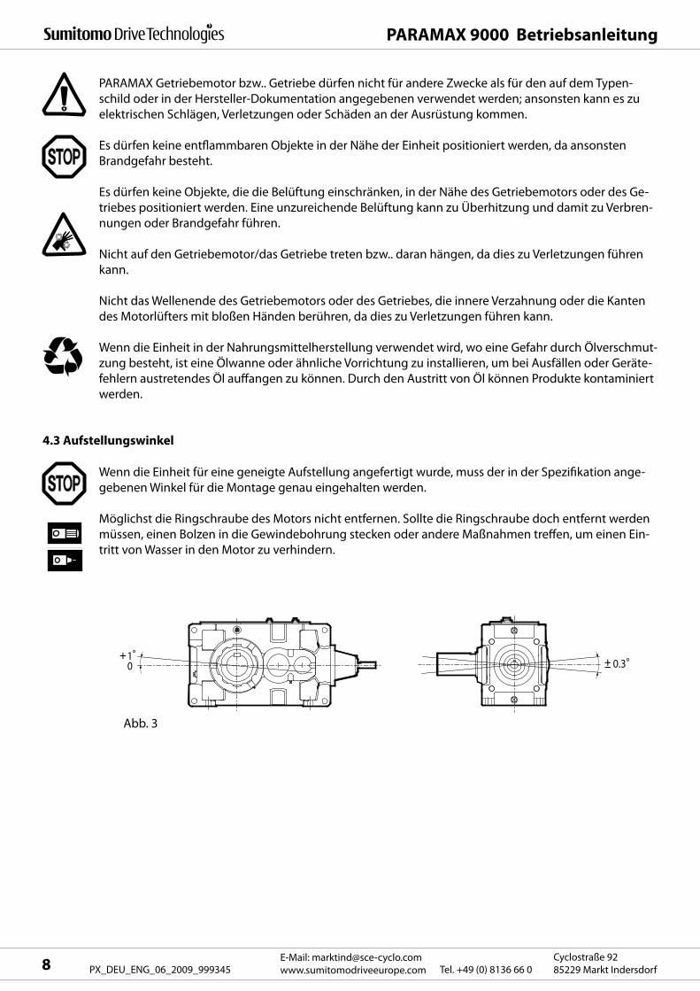
Abb. 3
PARAMAX Getriebemotor bzw.. Getriebe dürfen nicht für andere Zwecke als für den auf dem Typen-
schild oder in der Hersteller-Dokumentation angegebenen verwendet werden; ansonsten kann es zu
elektrischen Schlägen, Verletzungen oder Schäden an der Ausrüstung kommen.
Es dürfen keine entflammbaren Objekte in der Nähe der Einheit positioniert werden, da ansonsten
Brandgefahr besteht.
Es dürfen keine Objekte, die die Belüftung einschränken, in der Nähe des Getriebemotors oder des Ge-
triebes positioniert werden. Eine unzureichende Belüftung kann zu Überhitzung und damit zu Verbren-
nungen oder Brandgefahr führen.
Nicht auf den Getriebemotor/das Getriebe treten bzw.. daran hängen, da dies zu Verletzungen führen
kann.
Nicht das Wellenende des Getriebemotors oder des Getriebes, die innere Verzahnung oder die Kanten
des Motorlüfters mit bloßen Händen berühren, da dies zu Verletzungen führen kann.
Wenn die Einheit in der Nahrungsmittelherstellung verwendet wird, wo eine Gefahr durch Ölverschmut-
zung besteht, ist eine Ölwanne oder ähnliche Vorrichtung zu installieren, um bei Ausfällen oder Geräte-
fehlern austretendes Öl auffangen zu können. Durch den Austritt von Öl können Produkte kontaminiert
werden.
4.3 Aufstellungswinkel
Wenn die Einheit für eine geneigte Aufstellung angefertigt wurde, muss der in der Spezifikation ange-
gebenen Winkel für die Montage genau eingehalten werden.
Möglichst die Ringschraube des Motors nicht entfernen. Sollte die Ringschraube doch entfernt werden
müssen, einen Bolzen in die Gewindebohrung stecken oder andere Maßnahmen treffen, um einen Ein-
tritt von Wasser in den Motor zu verhindern.
PARAMAX 9000 Betriebsanleitung
9E-Mail: [email protected]
www.sumitomodriveeurope.comTel. +49 (0) 8136 66 0Cyclostraße 92
85229 Markt Indersdorf PX_DEU_ENG_06_2009_999345
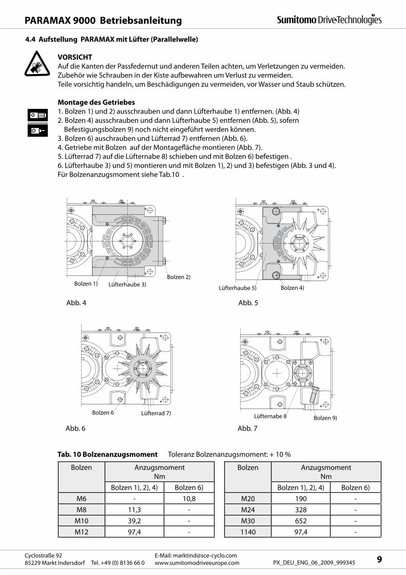
4.4 Aufstellung PARAMAX mit Lüfter (Parallelwelle)
VORSICHT
Auf die Kanten der Passfedernut und anderen Teilen achten, um Verletzungen zu vermeiden.
Zubehör wie Schrauben in der Kiste aufbewahren um Verlust zu vermeiden.
Teile vorsichtig handeln, um Beschädigungen zu vermeiden, vor Wasser und Staub schützen.
Montage des Getriebes
1. Bolzen 1) und 2) ausschrauben und dann Lüfterhaube 1) entfernen. (Abb. 4)
2. Bolzen 4) ausschrauben und dann Lüfterhaube 5) entfernen (Abb. 5), sofern
Befestigungsbolzen 9) noch nicht eingeführt werden können.
3. Bolzen 6) auschrauben und Lüfterrad 7) entfernen (Abb. 6).
4. Getriebe mit Bolzen auf der Montagefläche montieren (Abb. 7).
5. Lüfterrad 7) auf die Lüfternabe 8) schieben und mit Bolzen 6) befestigen .
6. Lüfterhaube 3) und 5) montieren und mit Bolzen 1), 2) und 3) befestigen (Abb. 3 und 4).
Für Bolzenanzugsmoment siehe Tab.10 .
Abb. 4 Abb. 5
Abb. 6 Abb. 7
Tab. 10 Bolzenanzugsmoment Toleranz Bolzenanzugsmoment: + 10 %
Bolzen Anzugsmoment
Nm
Bolzen 1), 2), 4) Bolzen 6)
M6 - 10,8
M8 11,3 -
M10 39,2 -
M12 97,4 -
Bolzen Anzugsmoment
Nm
Bolzen 1), 2), 4) Bolzen 6)
M20 190 -
M24 328 -
M30 652 -
1140 97,4 -
Lüfternabe 8 Bolzen 9)Bolzen 6 Lüfterrad 7)
Lüfterhaube 3)Bolzen 1)Bolzen 2)
Lüfterhaube 5) Bolzen 4)
PARAMAX 9000 Betriebsanleitung
E-Mail: [email protected]
www.sumitomodriveeurope.com Tel. +49 (0) 8136 66 0Cyclostraße 92
85229 Markt Indersdorf10 PX_DEU_ENG_06_2009_999345
5. Einsatzbereich
6. Verbindung mit anderen Maschinen
Decken Sie drehende Teile mit geeigneten Vorrichtungen ab; anderenfalls besteht Verletzungsgefahr.
Wenn das PARAMAX DRIVE mit einer Last verbunden wird, ist zu überprüfen, dass die Fluchtungs-
abweichung mit den in der Wartungsanleitung, den Zeichnungen, dem Katalog usw. angegebenen
Werten übereinstimmt; andernfalls können aufgrund der Abweichung Schäden am System entstehen.
Die entsprechenden Schrauben sind mit dem in den Zeichnungen, Katalogen usw. angegebenen
Drehmoment festzuziehen; andernfalls kann das System durch lose Teile beschädigt werden.
Wenn für die Verbindung der Anlage mit einer anderen Maschine ein Riemen verwendet wird, so ist
zu gewährleisten, dass die Riemenspannung und die Parallelitätsabweichung der Riemenscheibe
innerhalb der vorgegebenen Toleranzen liegen. Wird die Anlage direkt mit einer anderen Maschine
verbunden, ist darauf zu achten, dass die vorgeschriebenen Grenzwerte der Genauigkeitsabweichung
dieser Verbindung eingehalten werden; andernfalls kann das System durch eventuelle Abweichungen
beschädigt werden.
Wenn die Abtriebswelle des PARAMAX DRIVE frei drehend (d.h. ohne Last) bewegt werden soll, muss
vorher die Passfeder entfernt werden; andernfalls besteht Verletzungsgefahr.
Überprüfen Sie die Drehrichtung, bevor Sie die PARAMAX DRIVE mit einer Antriebmaschine verbinden.
Eine unvorhergesehene Drehrichtung kann zu Verletzungen und Schäden am System führen.
Umgebungsluftfeuchtigkeit : 85 % max.
Höhe : 1000 m max.
Umgebungsluft : Frei von korrosiven und explosiven Gasen sowie Dampf. ( Anwendungen im ATEX
nach Absprache mit dem Werk möglich. Siehe Kapitel 14)
Außerdem muss die Umgebung staubfrei und gut belüftet sein.
Aufstellungsort: Innen, möglichst staubfrei und ohne Spritzwasser.
Für die Aufstellung unter anderen als den oben genannten Bedingungen sind Sonderausführungen
erforderlich.
Umgebungstemperatur : -10°C bis +40°C
Ein Betrieb bei Umgebungstemperaturen unterhalb von -–10 0C, sowie über +40 0C ist werkseitig
abzustimmen.
Bei Verwendung einer Ölheizung ( Umgebungstemperatur –10 0C ) muss an dieser permanent eine
Spannung anliegen.
Ein integriertes Thermostat steuert die Ölheizung bei Bedarf an.
A
X X
B
PARAMAX 9000 Betriebsanleitung
11E-Mail: [email protected]
www.sumitomodriveeurope.comTel. +49 (0) 8136 66 0Cyclostraße 92
85229 Markt Indersdorf PX_DEU_ENG_06_2009_999345
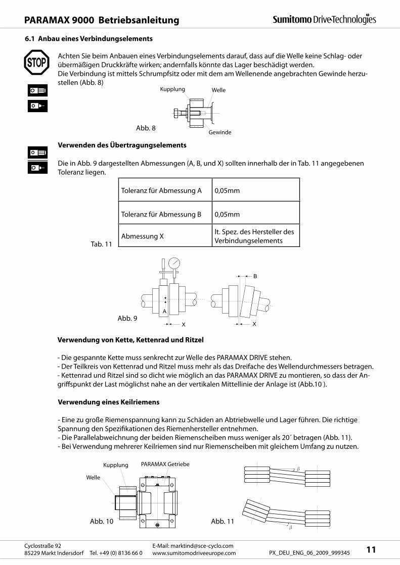
6.1 Anbau eines Verbindungselements
Achten Sie beim Anbauen eines Verbindungselements darauf, dass auf die Welle keine Schlag- oder
übermäßigen Druckkräfte wirken; andernfalls könnte das Lager beschädigt werden.
Die Verbindung ist mittels Schrumpfsitz oder mit dem am Wellenende angebrachten Gewinde herzu-
stellen (Abb. 8)
Die in Abb. 9 dargestellten Abmessungen (A, B, und X) sollten innerhalb der in Tab. 11 angegebenen
Toleranz liegen.
Toleranz für Abmessung A 0,05mm
Toleranz für Abmessung B 0,05mm
Abmessung Xlt. Spez. des Hersteller des
VerbindungselementsTab. 11
Abb. 9
Verwendung von Kette, Kettenrad und Ritzel
- Die gespannte Kette muss senkrecht zur Welle des PARAMAX DRIVE stehen.
- Der Teilkreis von Kettenrad und Ritzel muss mehr als das Dreifache des Wellendurchmessers betragen.
- Kettenrad und Ritzel sind so dicht wie möglich an das PARAMAX DRIVE zu montieren, so dass der An-
griffspunkt der Last möglichst nahe an der vertikalen Mittellinie der Anlage ist (Abb.10 ).
Abb. 10 Abb. 11
Verwenden des Übertragungselements
Verwendung eines Keilriemens
- Eine zu große Riemenspannung kann zu Schäden an Abtriebwelle und Lager führen. Die richtige
Spannung den Spezifikationen des Riemenhersteller entnehmen.
- Die Parallelabweichnung der beiden Riemenscheiben muss weniger als 20´ betragen (Abb. 11).
- Bei Verwendung mehrerer Keilriemen sind nur Riemenscheiben mit gleichem Umfang zu nutzen.
Gewinde
WelleKupplung
Abb. 8
Welle
Kupplung PARAMAX Getriebe
(B)
(HB)
(ZS)
( a)
((
( c)( b )
((ZS)(K)
(LV)( ZY
( g)( h)
PARAMAX 9000 Betriebsanleitung
E-Mail: [email protected]
www.sumitomodriveeurope.com Tel. +49 (0) 8136 66 0Cyclostraße 92
85229 Markt Indersdorf12 PX_DEU_ENG_06_2009_999345
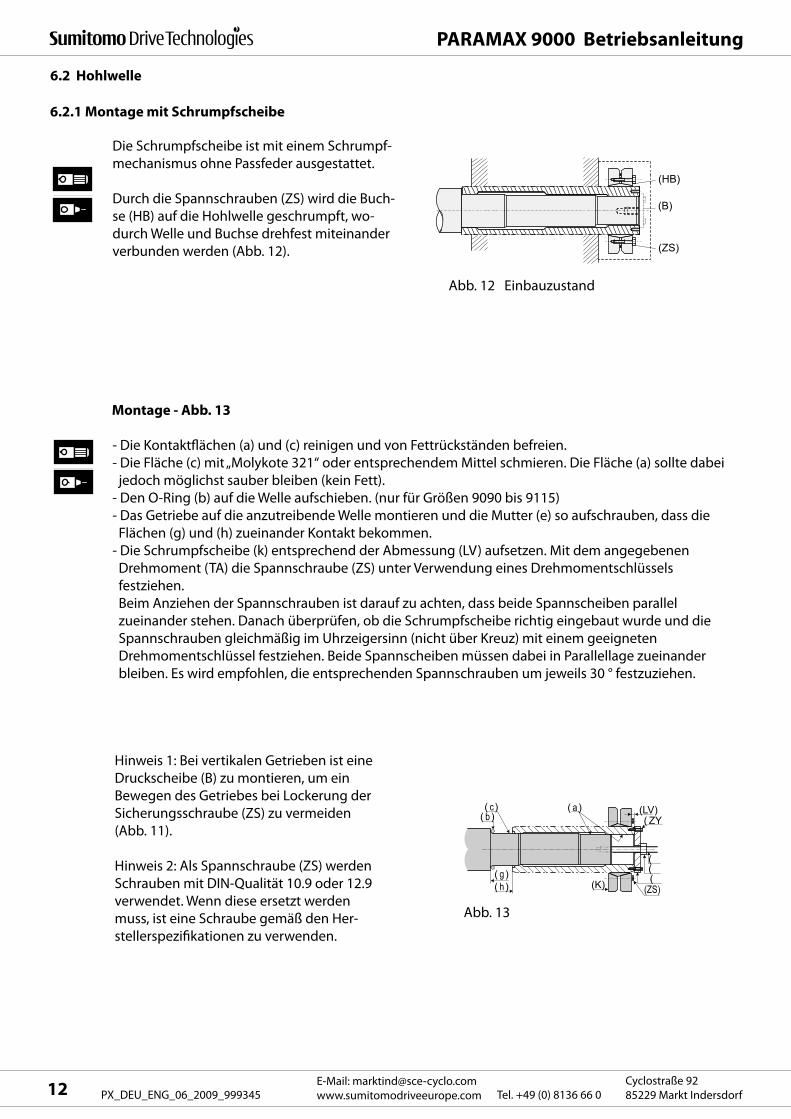
6.2 Hohlwelle
Die Schrumpfscheibe ist mit einem Schrumpf-
mechanismus ohne Passfeder ausgestattet.
Durch die Spannschrauben (ZS) wird die Buch-
se (HB) auf die Hohlwelle geschrumpft, wo-
durch Welle und Buchse drehfest miteinander
verbunden werden (Abb. 12).
Abb. 12 Einbauzustand
Montage - Abb. 13
- Die Kontaktflächen (a) und (c) reinigen und von Fettrückständen befreien.
- Die Fläche (c) mit „Molykote 321“ oder entsprechendem Mittel schmieren. Die Fläche (a) sollte dabei
jedoch möglichst sauber bleiben (kein Fett).
- Den O-Ring (b) auf die Welle aufschieben. (nur für Größen 9090 bis 9115)
- Das Getriebe auf die anzutreibende Welle montieren und die Mutter (e) so aufschrauben, dass die
Flächen (g) und (h) zueinander Kontakt bekommen.
- Die Schrumpfscheibe (k) entsprechend der Abmessung (LV) aufsetzen. Mit dem angegebenen
Drehmoment (TA) die Spannschraube (ZS) unter Verwendung eines Drehmomentschlüssels
festziehen.
Beim Anziehen der Spannschrauben ist darauf zu achten, dass beide Spannscheiben parallel
zueinander stehen. Danach überprüfen, ob die Schrumpfscheibe richtig eingebaut wurde und die
Spannschrauben gleichmäßig im Uhrzeigersinn (nicht über Kreuz) mit einem geeigneten
Drehmomentschlüssel festziehen. Beide Spannscheiben müssen dabei in Parallellage zueinander
bleiben. Es wird empfohlen, die entsprechenden Spannschrauben um jeweils 30 ° festzuziehen.
Hinweis 1: Bei vertikalen Getrieben ist eine
Druckscheibe (B) zu montieren, um ein
Bewegen des Getriebes bei Lockerung der
Sicherungsschraube (ZS) zu vermeiden
(Abb. 11).
Hinweis 2: Als Spannschraube (ZS) werden
Schrauben mit DIN-Qualität 10.9 oder 12.9
verwendet. Wenn diese ersetzt werden
muss, ist eine Schraube gemäß den Her-
stellerspezifikationen zu verwenden.
Abb. 13
6.2.1 Montage mit Schrumpfscheibe
(n) ( f) (m)
( ZY)
( a)
( e ) ( d )( c)( b )
( f)
( g)
( f)
( h )
( g )
( d )
( n )
( J)
PARAMAX 9000 Betriebsanleitung
13E-Mail: [email protected]
www.sumitomodriveeurope.comTel. +49 (0) 8136 66 0Cyclostraße 92
85229 Markt Indersdorf PX_DEU_ENG_06_2009_999345
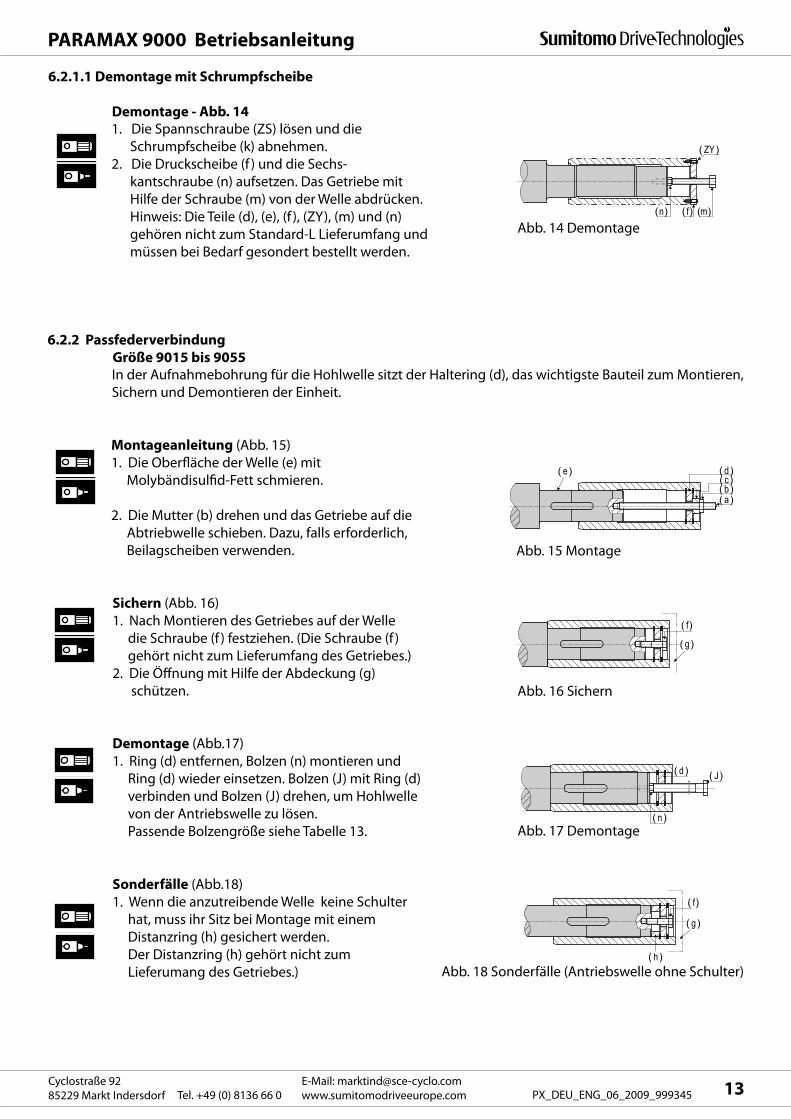
Demontage - Abb. 141. Die Spannschraube (ZS) lösen und die
Schrumpfscheibe (k) abnehmen.
2. Die Druckscheibe (f ) und die Sechs-
kantschraube (n) aufsetzen. Das Getriebe mit
Hilfe der Schraube (m) von der Welle abdrücken.
Hinweis: Die Teile (d), (e), (f ), (ZY), (m) und (n)
gehören nicht zum Standard-L Lieferumfang und
müssen bei Bedarf gesondert bestellt werden.
Abb. 14 Demontage
6.2.2 Passfederverbindung
Größe 9015 bis 9055In der Aufnahmebohrung für die Hohlwelle sitzt der Haltering (d), das wichtigste Bauteil zum Montieren,
Sichern und Demontieren der Einheit.
Montageanleitung (Abb. 15)
1. Die Oberfläche der Welle (e) mit
Molybändisulfid-Fett schmieren.
2. Die Mutter (b) drehen und das Getriebe auf die
Abtriebwelle schieben. Dazu, falls erforderlich,
Beilagscheiben verwenden.
Sichern (Abb. 16)
1. Nach Montieren des Getriebes auf der Welle
die Schraube (f ) festziehen. (Die Schraube (f )
gehört nicht zum Lieferumfang des Getriebes.)
2. Die Öffnung mit Hilfe der Abdeckung (g)
schützen.
Demontage (Abb.17)
1. Ring (d) entfernen, Bolzen (n) montieren und
Ring (d) wieder einsetzen. Bolzen (J) mit Ring (d)
verbinden und Bolzen (J) drehen, um Hohlwelle
von der Antriebswelle zu lösen.
Passende Bolzengröße siehe Tabelle 13.
Sonderfälle (Abb.18)
1. Wenn die anzutreibende Welle keine Schulter
hat, muss ihr Sitz bei Montage mit einem
Distanzring (h) gesichert werden.
Der Distanzring (h) gehört nicht zum
Lieferumang des Getriebes.)
Abb. 15 Montage
Abb. 16 Sichern
Abb. 17 Demontage
Abb. 18 Sonderfälle (Antriebswelle ohne Schulter)
6.2.1.1 Demontage mit Schrumpfscheibe
( a )
( e ) d( b)( )
( f)
( g )
( n )
( J )
Fi 2
d( )
( f)
( g )
( h)
PARAMAX 9000 Betriebsanleitung
E-Mail: [email protected]
www.sumitomodriveeurope.com Tel. +49 (0) 8136 66 0Cyclostraße 92
85229 Markt Indersdorf14 PX_DEU_ENG_06_2009_999345
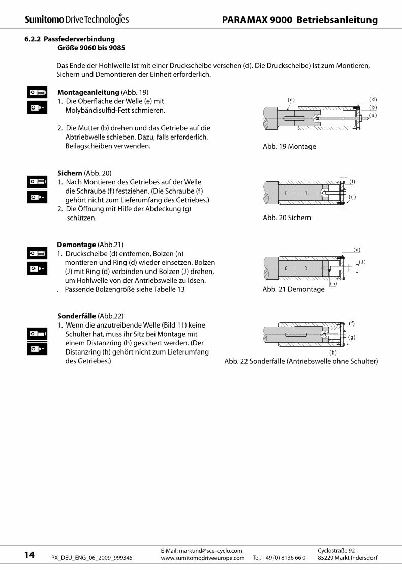
6.2.2 Passfederverbindung
Größe 9060 bis 9085
Das Ende der Hohlwelle ist mit einer Druckscheibe versehen (d). Die Druckscheibe) ist zum Montieren,
Sichern und Demontieren der Einheit erforderlich.
Demontage (Abb.21)
1. Druckscheibe (d) entfernen, Bolzen (n)
montieren und Ring (d) wieder einsetzen. Bolzen
(J) mit Ring (d) verbinden und Bolzen (J) drehen,
um Hohlwelle von der Antriebswelle zu lösen.
. Passende Bolzengröße siehe Tabelle 13
Sonderfälle (Abb.22)
1. Wenn die anzutreibende Welle (Bild 11) keine
Schulter hat, muss ihr Sitz bei Montage mit
einem Distanzring (h) gesichert werden. (Der
Distanzring (h) gehört nicht zum Lieferumfang
des Getriebes.)
Abb. 19 Montage
Abb. 20 Sichern
Abb. 21 Demontage
Abb. 22 Sonderfälle (Antriebswelle ohne Schulter)
Montageanleitung (Abb. 19)
1. Die Oberfläche der Welle (e) mit
Molybändisulfid-Fett schmieren.
2. Die Mutter (b) drehen und das Getriebe auf die
Abtriebwelle schieben. Dazu, falls erforderlich,
Beilagscheiben verwenden.
Sichern (Abb. 20)
1. Nach Montieren des Getriebes auf der Welle
die Schraube (f ) festziehen. (Die Schraube (f )
gehört nicht zum Lieferumfang des Getriebes.)
2. Die Öffnung mit Hilfe der Abdeckung (g)
schützen.
M2M
M1
s
tT
LV
ZS N-ZY
L4(45 )
DZ d DS U1.6
J
D d1 dw z
LZH
LS
L3L2
DETAIL A L1
D1
LR(45 )R
(9015~9085)
1.6
LR(45 )R
(9090~9115)
1.6
A
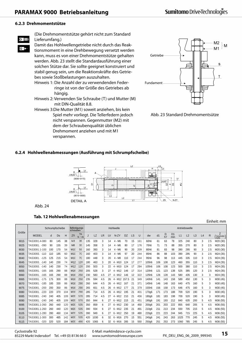
MODEL d Ds H ZS TAN m J LZ LR LV N-ZY DZ LS U dw d1 D
h7D1min L1 L2 L3 L4 R
Z( )
9015 TAS3091.4-080 80 145 38 M8 35 135 328 3 14 4 - M6 70 15 161 60h6 61 63 78 325 240 80 3 2.5 M20 (30)9025 TAS3081. -090 90 155 39 M8 35 145 358 3 14 4 - M6 80 17 176 70h6 71 73 88 355 270 80 3 2.5 M20 (30)9030 TAS3091.1-100 100 170 54 M10 59 160 393 3 14 4 - M6 90 20 209 80h6 81 83 98 390 295 90 3 2.5 M20 (30)9035 TAS3093. -110 110 185 60 M10 70 160 403 3 14 4 - M6 97 20 244 85h6 86 88 103 390 295 90 3 2.5 M24 (35)9040 TAS3081. -125 125 215 54 M10 70 180 448 3 20 4 - M8 110 17 244 95h6 96 98 113 445 335 110 3 2.5 M24 (35)9045 TAS3093. -140 140 230 74 M12 120 180 463 3 20 4 - M10 124 17 277 105h6 106 108 123 460 355 110 3 2.5 M24 (35)9050 TAS3093. -140 140 230 74 M12 120 200 503 3 22 4 - M10 124 17 284 105h6 106 108 123 500 380 110 3 2.5 M24 (35)9055 TAS3091. -165 165 290 88 M16 250 205 528 3 27 4 - M12 146 17 314 120h6 121 123 138 525 385 120 3 2.5 M24 (35)9060 TAS3091. -165 165 290 88 M16 250 230 583 4.5 27 4 - M12 146 12 322 125h6 126 128 143 580 435 130 3 3 M24 (35)9065 TAS3091. -175 175 300 88 M16 250 235 594 4.5 26 4 - M12 157.5 21 349 140h6 141 143 158 589 450 130 5 3 M30 (45)9070 TAS3081. -185 185 330 86 M16 290 260 644 4.5 26 4 - M12 167 21 371 145h6 146 148 163 640 475 160 5 3 M30 (45)9075 TAS3081. -200 200 350 86 M16 290 265 651 4.5 26 4 - M12 177 21 379 155h6 156 158 173 646 475 160 5 3 M30 (45)9080 TAS3081. -220 220 370 104 M16 290 285 714 4.5 26 4 - M12 195 21 401 170g6 171 173 188 709 520 190 5 3 M30 (45)9085 TAS3081. -240 240 405 109 M20 570 285 714 4.5 27 4 - M12 210 21 456 180g6 181 183 198 709 520 190 5 3 M30 (45)9090 TAS3081. -240 240 405 109 M20 570 350 844 6 27 6 - M12 215 21 451 190g6 191 193 212 840 635 200 5 4.5 M36 (55)9095 TAS3081.1-260 260 440 120 M20 535 350 859 6 27 6 - M12 230 14 450 200g6 201 203 222 855 640 205 5 4.5 M36 (55)9100 TAS3081.1-260 260 440 120 M20 535 390 934 6 27 6 - M12 235 21 491 210g6 211 213 234 930 705 215 5 4.5 M36 (55)9105 TAS3081.1-280 280 460 134 M20 535 390 949 6 27 6 - M12 250 19 480 220g6 221 223 244 945 715 225 5 4.5 M36 (55)9110 TAS3081.1-300 300 485 142 M20 535 420 1030 6 32 6 - M16 270 15 551 240g6 241 243 263 1025 770 245 5 4.5 M36 (55)9115 TAS3091. -320 320 520 184 M20 490 420 1065 6 32 6 - M16 285 15 550 250g6 251 253 273 1060 785 245 5 4.5 M36 (55)
GrößeSchrumpfscheibe Hohlwelle Antriebswelle
Einheit: mm
Befestigungs-schrauben
ZS TATTN m
M8 35M8 35
M10 59M10 70M10 70M12 120M12 120M16 250M16 250M16 250M16 290M16 290M16 290M20 570M20 570M20 535M20 535M20 535M20 535M20 490
Befestigungs-schrauben
gg
Gewinde-tiefe
PARAMAX 9000 Betriebsanleitung
15E-Mail: [email protected]
www.sumitomodriveeurope.comTel. +49 (0) 8136 66 0Cyclostraße 92
85229 Markt Indersdorf PX_DEU_ENG_06_2009_999345
Tab. 12 Hohlwellenabmessungen
Abb. 24
(Die Drehmomentstütze gehört nicht zum Standard
Lieferumfang.)
Damit das Hohlwellengetriebe nicht durch das Reak-
tionsmoment in eine Drehbewegung versetzt werden
kann, muss es von einer Drehmomentstütze gehalten
werden. Abb. 23 stellt die Standardausführung einer
solchen Stütze dar. Sie sollte geeignet konstruiert und
stabil genug sein, um die Reaktionskräfte des Getrie-
bes sowie Stoßbelastungen auszuhalten.
Hinweis 1: Die Anzahl der zu verwendenden Feder-
ringe ist von der Größe des Getriebes ab
hängig.
Hinweis 2: Verwenden Sie Schraube (T) und Mutter (M)
mit DIN-Qualität 8.8.
Hinweis 3:Die Mutter (M1) soweit anziehen, bis kein
Spiel mehr vorliegt. Die Tellerfedern jedoch
nicht verspannen. Gegenmutter (M2) mit
dem der Schraubenqualität üblichen
Drehmoment anziehen und mit M1
verspannen.
Abb. 23 Standard Drehmomentsütze
6.2.4 Hohlwellenabmessungen (Ausführung mit Schrumpfscheibe)
6.2.3 Drehmomentstütze
Getriebe
Fundament
Y
P
X Js
9/h9
D
LR(45 )R
1.6
LSL
LSL
Z1D
f
L4 L5L3
L2L1
D- 0
.2- 0
.4
U
L / 2
D1
D2 ZAZ1D Z
f
L4 L5L3
L2L1LG
LH
D- 0
.2- 0
.4
U(e
xcep
t 901
5)
L / 2
D1
A
DETAIL A
L LG LH Z LS U DD1min L1 L2 L3 L4 L5 X Y Z
Z1 (Gewinde-tiefe
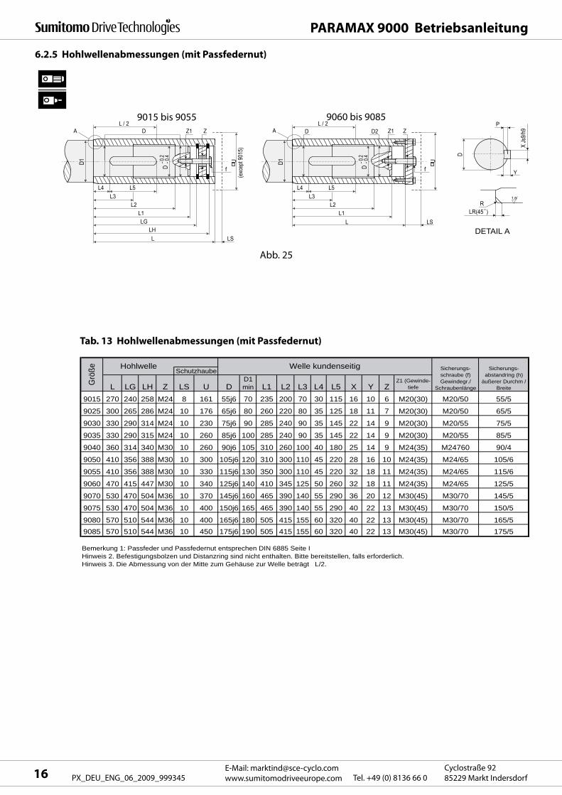
9015 270 240 258 M24 8 161 55j6 70 235 200 70 30 115 16 10 6 M20(30) M20/50 55/5
9025 300 265 286 M24 10 176 65j6 80 260 220 80 35 125 18 11 7 M20(30) M20/50 65/5
9030 330 290 314 M24 10 230 75j6 90 285 240 90 35 145 22 14 9 M20(30) M20/55 75/5
9035 330 290 315 M24 10 260 85j6 100 285 240 90 35 145 22 14 9 M20(30) M20/55 85/5
9040 360 314 340 M30 10 260 90j6 105 310 260 100 40 180 25 14 9 M24(35) M24760 90/4
9050 410 356 388 M30 10 300 105j6 120 310 300 110 45 220 28 16 10 M24(35) M24/65 105/6
9055 410 356 388 M30 10 330 115j6 130 350 300 110 45 220 32 18 11 M24(35) M24/65 115/6
9060 470 415 447 M30 10 340 125j6 140 410 345 125 50 260 32 18 11 M24(35) M24/65 125/5
9070 530 470 504 M36 10 370 145j6 160 465 390 140 55 290 36 20 12 M30(45) M30/70 145/5
9075 530 470 504 M36 10 400 150j6 165 465 390 140 55 290 40 22 13 M30(45) M30/70 150/5
9080 570 510 544 M36 10 400 165j6 180 505 415 155 60 320 40 22 13 M30(45) M30/70 165/59085 570 510 544 M36 10 450 175j6 190 505 415 155 60 320 40 22 13 M30(45) M30/70 175/5
Bemerkung 1: Passfeder und Passfedernut entsprechen DIN 6885 Seite I Hinweis 2. Befestigungsbolzen und Distanzring sind nicht enthalten. Bitte bereitstellen, falls erforderlich.Hinweis 3. Die Abmessung von der Mitte zum Gehäuse zur Welle beträgt L/2.
Sicherungs-abstandring (h)
äußerer Durchm / Breite
Grö
ße SchutzhaubeHohlwelle Welle kundenseitig Sicherungs-
schraube (f)Gewindegr./
Schraubenlänge
PARAMAX 9000 Betriebsanleitung
E-Mail: [email protected]
www.sumitomodriveeurope.com Tel. +49 (0) 8136 66 0Cyclostraße 92
85229 Markt Indersdorf16 PX_DEU_ENG_06_2009_999345
6.2.5 Hohlwellenabmessungen (mit Passfedernut)
9015 bis 9055 9060 bis 9085
Abb. 25
Tab. 13 Hohlwellenabmessungen (mit Passfedernut)
PARAMAX 9000 Betriebsanleitung
17E-Mail: [email protected]
www.sumitomodriveeurope.comTel. +49 (0) 8136 66 0Cyclostraße 92
85229 Markt Indersdorf PX_DEU_ENG_06_2009_999345
7. Elektrische Installation
Montage, Anschluss und Inbetriebnahme sowie Wartungs- und Reparaturarbeiten dürfen nur durch
qualifiziertes Fachpersonal erfolgen.
Vor Beginn jeder Arbeit am Motor oder Getriebemotor, besonders aber vor dem Öffnen von Abdeckun-
gen aktiver Teile, muss der Motor vorschriftsmäßig freigeschaltet sein.
Die 5 Sicherheitsregeln nach DIN VDE 0105 sind zu beachten.
Diese Elektromotoren entsprechen den gültigen Normen und Vorschriften und erfüllen die Forderun-
gen der Niederspannungsrichtlinie 73/23/EWG.
Der elektrische Anschluss eines standardmäßigen Sumitomo 3-Phasen-Motors wird nachfolgend be-
schrieben.
Informationen zu Bremsmotoren , Servomotoren , Gleichstrommotoren und Motoren anderer Hersteller
nach, falls zutreffend, sind in den jeweiligen Betriebsanleitungen enthalten.
Keine Arbeiten an der Einheit durchführen, wenn sie unter Strom steht. Immer den Netzstrom abschal-
ten, um elektrische Schläge zu vermeiden.
Die Einheit gemäß dem Schaltbild im Klemmenkasten oder der Betriebsanleitung mit dem Netzkabel
verbinden; ansonsten besteht die Gefahr elektrischer Schläge oder Brandgefahr.
Das Netzkabel nicht über Gebühr biegen, ziehen oder klammern; ansonsten besteht die Gefahr elektri-
scher Schläge oder Brandgefahr.
Den Erdungsbolzen mit Masse verbinden; ansonsten besteht die Gefahr elektrischer Schläge oder
Brandgefahr.Bei dem elektrischen Anschluss des Motors sowie weiterer elektrischen Komponenten ist den werk-
seitigen elektrischen Bezeichnungen und Anschlussbedingungen Folge zu leisten; ansonsten besteht
die Gefahr von Verbrennungen, elektrischen Schlägen, von Verletzungen und Brandgefahr. Der Motor
ist mit keinerlei Schutzvorrichtung ausgestattet. Trotzdem muss gemäß den werkseitigen elektrischen
Vorschriften ein Überlastungsschutz installiert werden. Es wird empfohlen, zusätzlich zum Überlas-
tungsschutz weitere Schutzvorrichtungen (Erdschlussschalter etc.) zu installieren, um Verbrennungen,
elektrische Schläge, Verletzungen und Brandgefahr zu vermeiden.
Beim Messen des Isolationswiderstands niemals die Klemmen berühren, um elektrische Schläge zu
vermeiden.
Wird ein Sterndreieckanlasser verwendet, dann nur einen mit einem elektromagnetischen Schalter auf
der primären Seite (3-Kontakt-Typ): ansonsten besteht Brandgefahr.
Wird für den Antrieb einen 400 V-Umformer verwendet, muss auf der Seite mit dem Umrichter ein Ent-
störfilter bzw. eine Entstördrossel montiert oder die motorseitige Isolierung verstärkt werden; ansons-
ten kann es durch den dielektrischen Durchbruch zu Brandgefahr oder zu Schäden an der Ausrüstung
kommen.
Bei Verwendung langer Kabel ist der Spannungsabfall zu beachten. Es sind deshalb Kabel mit entspre-
chendem Durchmesser zu wählen, damit dieser Wert 2 % nicht übersteigt.
7.1 Sicherheitshinweise
PARAMAX 9000 Betriebsanleitung
E-Mail: [email protected]
www.sumitomodriveeurope.com Tel. +49 (0) 8136 66 0Cyclostraße 92
85229 Markt Indersdorf18 PX_DEU_ENG_06_2009_999345
7.2 Messen des Isolationswiderstands
Vor dem Messen des Isolationswiderstands die Verbindung zwischen Motor und Steuerpult trennen.
Den Motor separat prüfen.
Den Isolationswiderstand vor dem Anschließen messen. Der Isolationswiderstand (R) variiert je nach
Motorleistung, Spannung, Isolationstyp, Spulentemperatur, Feuchtigkeit, Verschmutzung, Betriebsdau-
er, Testelektrifizierungsdauer etc. Im Normalfall sollte der Isolationswiderstand die Werte in Tabelle 14
übersteigen.
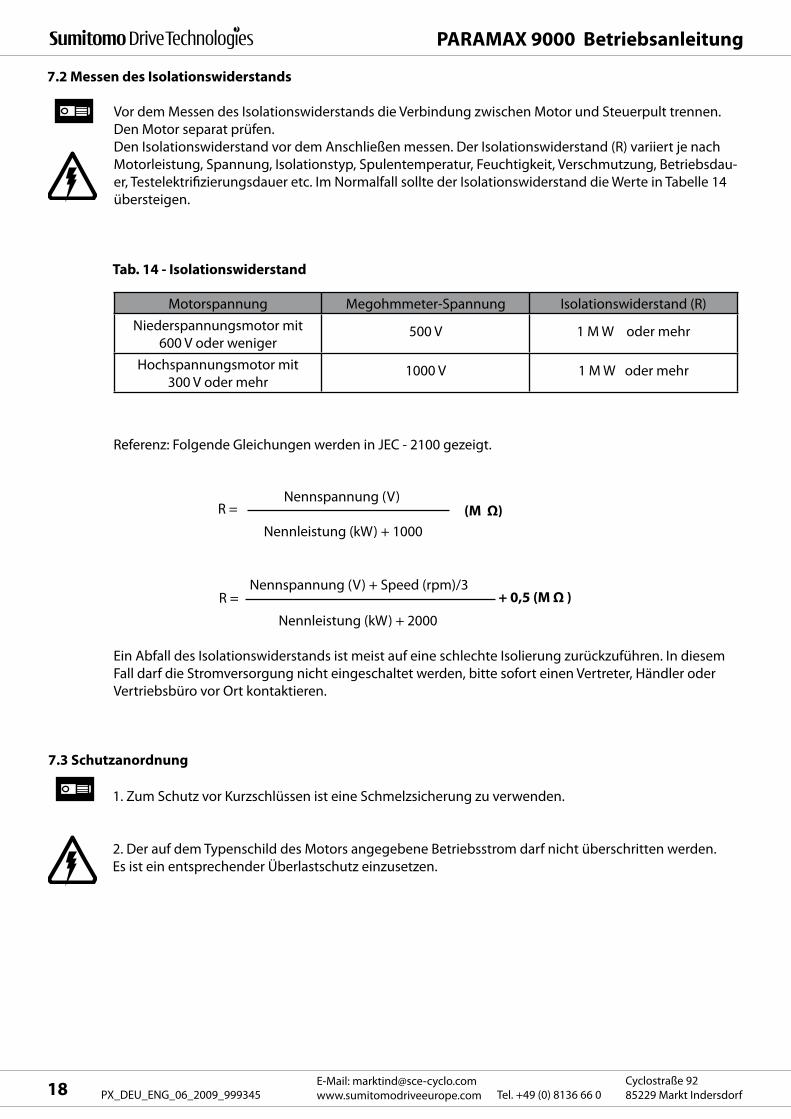
Tab. 14 - Isolationswiderstand
Ein Abfall des Isolationswiderstands ist meist auf eine schlechte Isolierung zurückzuführen. In diesem
Fall darf die Stromversorgung nicht eingeschaltet werden, bitte sofort einen Vertreter, Händler oder
Vertriebsbüro vor Ort kontaktieren.
1. Zum Schutz vor Kurzschlüssen ist eine Schmelzsicherung zu verwenden.
2. Der auf dem Typenschild des Motors angegebene Betriebsstrom darf nicht überschritten werden.
Es ist ein entsprechender Überlastschutz einzusetzen.
7.3 Schutzanordnung
Referenz: Folgende Gleichungen werden in JEC - 2100 gezeigt.
R =Nennspannung (V)
Nennleistung (kW) + 1000
(M Ω)
R =Nennspannung (V) + Speed (rpm)/3
Nennleistung (kW) + 2000
+ 0,5 (M Ω )
Motorspannung Megohmmeter-Spannung Isolationswiderstand (R)
Niederspannungsmotor mit
600 V oder weniger500 V 1 M W oder mehr
Hochspannungsmotor mit
300 V oder mehr1000 V 1 M W oder mehr
MC
OLR
R
U Y
S
V Z
T
W X
R
U1 V1 W1 U2 W2 V2
S T
MCH1 MCL
MCH2
OLR OLR
MC
OLR
R
U
S
V
T
W
R
U V W Y X Z
S T
MC DMCM
MC
OLR
Y
PARAMAX 9000 Betriebsanleitung
19E-Mail: [email protected]
www.sumitomodriveeurope.comTel. +49 (0) 8136 66 0Cyclostraße 92
85229 Markt Indersdorf PX_DEU_ENG_06_2009_999345
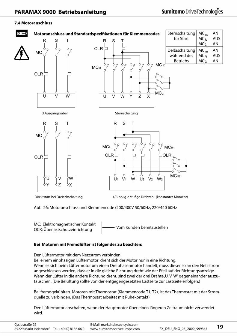
7.4 Motoranschluss
Motoranschluss und Standardspezifikationen für Klemmencodes
3 Ausgangskabel Sternschaltung
Direktstart bei Dreieckschaltung 4/8-polig 2-stufige Drehzahl (konstantes Moment)
Abb. 26: Motoranschluss und Klemmencode (200/400V 50/60Hz, 220/440 60Hz
MC: Elektromagnetischer Kontakt
OCR: ÜberlastschutzeinrichtungVom Kunden bereitzustellen
Bei Motoren mit Fremdlüfter ist folgendes zu beachten:
Den Lüftermotor mit dem Netzstrom verbinden.
Bei einem einphasigen Lüftermotor dreht sich der Motor nur in eine Richtung.
Wenn es sich beim Lüftermotor um einen Dreiphasenmotor handelt, muss dieser so an den Netzstrom
angeschlossen werden, dass er in die gleiche Richtung dreht wie der Pfeil auf der Richtungsanzeige.
Wenn der Lüfter in die andere Richtung dreht, sind zwei der drei Drähte ‚U, V, W‘ gegeneinander auszu-
tauschen. (Die Belüftung sollte von der entgegengesetzten Lastseite zur Lastseite erfolgen.)
Bei fremdgekühlten Motoren mit Thermostat (Klemmencode T1, T2), ist das Thermostat mit der Strom-
quelle zu verbinden. (Das Thermostat arbeitet mit Ruhekontakt)
Den Lüftermotor abschalten, wenn der Hauptmotor über einen längeren Zeitraum nicht verwendet
wird.
Sternschaltung
für Start
MC AN
MC AUS
MC AN
Deltaschaltung
während des
Betriebs
MC AN
MC AUS
MC AN
PARAMAX 9000 Betriebsanleitung
E-Mail: [email protected]
www.sumitomodriveeurope.com Tel. +49 (0) 8136 66 0Cyclostraße 92
85229 Markt Indersdorf20 PX_DEU_ENG_06_2009_999345
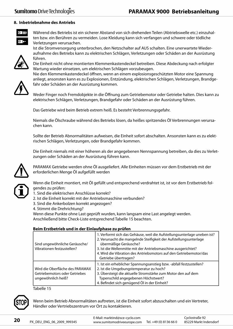
8. Inbetriebnahme des Antriebs
Während des Betriebs ist ein sicherer Abstand von sich drehenden Teilen (Abtriebswelle etc.) einzuhal-
ten bzw. ein Berühren zu vermeiden. Lose Kleidung kann sich verfangen und schwere oder tödliche
Verletzungen verursachen.
Ist die Stromversorgung unterbrochen, den Netzschalter auf AUS schalten. Eine unerwartete Wieder-
aufnahme des Betriebs kann zu elektrischen Schlägen, Verletzungen oder Schäden an der Ausrüstung
führen.
Die Einheit nicht ohne montierten Klemmenkastendeckel betreiben. Diese Abdeckung nach erfolgter
Wartung wieder einsetzen, um elektrischen Schlägen vorzubeugen.
Nie den Klemmenkastendeckel öffnen, wenn an einem explosionsgeschützten Motor eine Spannung
anliegt, ansonsten kann es zu Explosionen, Entzündung, elektrischen Schlägen, Verletzungen, Brandge-
fahr oder Schäden an der Ausrüstung kommen.
Weder Finger noch Fremdobjekte in die Öffnung zum Getriebemotor oder Getriebe halten. Dies kann zu
elektrischen Schlägen, Verletzungen, Brandgefahr oder Schäden an der Ausrüstung führen.
Das Getriebe wird beim Betrieb extrem heiß. Es besteht Verbrennungsgefahr.
Niemals die Ölschraube während des Betriebs lösen, da heißes spritzendes Öl Verbrennungen verursa-
chen kann.
Sollte der Betrieb Abnormalitäten aufweisen, die Einheit sofort abschalten. Ansonsten kann es zu elekt-
rischen Schlägen, Verletzungen, oder Brandgefahr kommen.
Die Einheit niemals mit einer höheren als der angegebenen Nennspannung betreiben, da dies zu Verlet-
zungen oder Schäden an der Ausrüstung führen kann.
PARAMAX Getriebe werden ohne Öl ausgeliefert. Alle Einheiten müssen vor dem Erstbetrieb mit der
erforderlichen Menge Öl aufgefüllt werden
Wenn beim Betrieb Abnormalitäten auftreten, ist die Einheit sofort abzuschalten und ein Vertreter,
Händler oder Vertriebszentrum vor Ort zu kontaktieren.
Sind ungewöhnliche Geräusche/
Vibrationen festzustellen?
1. Verformt sich das Gehäuse, weil die Aufstellungsunterlage uneben ist?
2. Verursacht die mangelnde Steifigkeit der Aufstellungsunterlage
übermäßige Geräusche?
3. Ist die Wellenmitte mit der Antriebsmaschine ausgerichtet?
4. Wird die Vibration des Antriebsmotors auf den Getriebemotor/das
Getriebe übertragen?
Wird die Oberfläche des PARAMAX
Getriebemotors oder Getriebes
ungewöhnlich heiß?
1. Ist ein erheblicher Spannungsanstieg bzw. -abfall festzustellen?
2. Ist die Umgebungstemperatur zu hoch?
3. Übersteigt die aktuelle Stromstärke zum Motor den auf dem
Typenschild angegebenen Höchstwert?
4. Befindet sich genügend Öl in der Einheit?
Wenn die Einheit montiert, mit Öl gefüllt und entsprechend verdrahtet ist, ist vor dem Erstbetrieb fol-
gendes zu prüfen:
1. Sind die elektrischen Anschlüsse korrekt?
2. Ist die Einheit korrekt mit der Antriebsmaschine verbunden?
3. Sind die Ankerbolzen korrekt angezogen?
4. Stimmt die Drehrichtung?
Wenn diese Punkte ohne Last geprüft wurden, kann langsam eine Last angelegt werden.
Anschließend bitte Check-Liste entsprechend Tabelle 15 beachten.
Beim Erstbetrieb und in der Einlaufphase zu prüfen
Tabelle 15
PARAMAX 9000 Betriebsanleitung
21E-Mail: [email protected]
www.sumitomodriveeurope.comTel. +49 (0) 8136 66 0Cyclostraße 92
85229 Markt Indersdorf PX_DEU_ENG_06_2009_999345
9. Tägliche Inspektion und Wartung
Die Einheit nicht berühren, wenn sie unter Strom steht. Immer zuerst die Stromversorgung abschalten;
ansonsten besteht die Gefahr elektrischer Schläge.
Während der Wartung oder Inspektion Abstand von sich drehenden Teilen (Abtriebswelle etc.) halten
fern bzw. diese nicht berühren. Lose Kleidung kann sich verfangen und schwere oder tödliche Verlet-
zungen verursachen.
Auf keinen Fall explosionsgeschützte Motoren auseinander nehmen oder modifizieren; ansonsten be-
steht die Gefahr von Explosionen, Selbstentzündung, elektrischer Schläge oder Schäden an der Ausrüs-
tung.
Die Zuleitung eines explosionsgeschützten Motors muss den werkseitigen elektrischen Bezeichnungen,
den Anschlussbedingungen und dem Handbuch zum Explosionsschutz sowie der Betriebsanleitung
übereinstimmen; ansonsten besteht die Gefahr elektrischer Schläge, von Verletzungen, Explosion,
Brandgefahr oder von Schäden an der Ausrüstung.
Niemals Finger oder Fremdobjekte in die Öffnung zum Getriebemotor oder Getriebe halten. Dies kann
zu elektrischen Schlägen, Verletzungen, Brandgefahr oder Schäden an der Ausrüstung führen.
Der Getriebemotor bzw. das Getriebe wird beim Betrieb extrem heiß. Ein Berühren mit bloßen Händen
kann zu Verbrennungen führen.
Beim Messen des Isolationswiderstands niemals die Klemmen berühren, um elektrische Schläge zu
vermeiden.
Die Einheit nie ohne montierte Schutzabdeckung für sich drehende Teile betreiben; Lose Kleidung kann
sich verfangen und schwere oder tödliche Verletzungen verursachen.
Jegliche beim Betrieb festgestellte Unregelmäßigkeiten müssen gemäß den Anweisungen in dieser
Betriebsanleitung umgehend identifiziert und korrigiert werden. Der Betrieb darf erst dann wieder
aufgenommen werden, wenn die Unregelmäßigkeit behoben ist.
Schmierstoffe sind gemäß den Anweisungen in der Betriebsanleitung zu wechseln. Es ist immer der
vom Hersteller empfohlene Schmierstoff zu verwenden.
Schmierstoffe dürfen nie während des Betriebs oder kurz danach gewechselt werden; es besteht Ver-
brennungsgefahr.
Die Motorlager sind gemäß den Anweisungen in der Betriebsanleitung nachzuschmieren.
Den Kontakt mit sich drehenden Teilen vermeiden; ansonsten besteht Verletzungsgefahr.
Niemals beschädigte PARAMAX Getriebemotoren oder Getriebe betreiben; ansonsten besteht die Ge-
fahr von Verletzungen, Feuer oder Schäden an der Ausrüstung.
Wir übernehmen keinerlei Haftung für Schäden oder Verletzungen, die sich aus der unerlaubten Verän-
derung von Geräten durch den Kunden ergeben.
Schmierstoffe aus PARAMAX Getriebemotoren oder Getrieben sind als Industrieabfälle zu entsorgen.
Bitte achten Sie auf die geltenden Bestimmungen.
Beim Messen des Isolationswiderstands an explosionsgeschützten Motoren muss sichergestellt werden,
dass die Umgebung frei ist von Gas, Dämpfen oder anderen explosiven Substanzen, damit die Gefahr
einer Explosion oder Selbstentzündung ausgeschlossen werden kann.
PARAMAX 9000 Betriebsanleitung
E-Mail: [email protected]
www.sumitomodriveeurope.com Tel. +49 (0) 8136 66 0Cyclostraße 92
85229 Markt Indersdorf22 PX_DEU_ENG_06_2009_999345
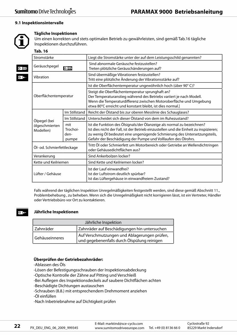
9.1 Inspektionsintervalle
Um einen korrekten und stets optimalen Betrieb zu gewährleisten, sind gemäß Tab.16 tägliche
Inspektionen durchzuführen.
Tab. 16
Stromstärke Liegt die Stromstärke unter der auf dem Leistungsschild genannten?
Geräuschpegel Sind abnormale Geräusche festzustellen?
Treten plötzliche Geräuschänderungen auf?
VibrationSind übermäßige Vibrationen festzustellen?
Tritt eine plötzliche Änderung der Vibrationsstärke auf?
Oberflächentemperatur
Ist die Oberflächentemperatur ungewöhnlich hoch (über 90° C)?
Steigt die Oberflächentemperatur sprunghaft an?
Der Temperaturanstieg während des Betriebs variiert je nach Modell.
Wenn die Temperaturdifferenz zwischen Motoroberfläche und Umgebung
etwa 80°C erreicht und konstant bleibt, ist dies normal.]
Ölpegel (bei
ölgeschmierten
Modellen)
Im Stillstand Reicht der Ölstand bis zur oberen Messlinie des Schauglases?
Im Stillstand Unterscheidet sich dieser Ölstand von dem im Ruhezustand?
mit
Trochoi-
den-
pumpe
Ist die Funktion des Ölsignals/der Ölanzeige als normal zu bezeichnen?
Ist dies nicht der Fall, ist der Betrieb einzustellen und die Einheit zu inspizieren;
zu wenig Öl bedeutet eine ungenügende Schmierung des Untersetzungsteils,
Gefahr der Beschädigung der Pumpe und Volllaufen des Ölrohrs.
Öl- od. SchmierfettleckageTritt Öl oder Schmierfett um Motorbereich oder Getriebe an Wellendichtringen
oder Gehäusedichtflächen aus?
Verankerung Sind Ankerbolzen locker?
Kette und Keilriemen Sind Kette und Keilriemen locker?
Lüfter / Gehäuse
Ist der Lauf einwandfrei?
Ist der Luftstrom deutlich spürbar?
Ist das Lüftergehäuse in einwandfreiem Zustand?
Falls während der täglichen Inspektion Unregelmäßigkeiten festgestellt werden, sind diese gemäß Abschnitt 11.,
Problembehebung , zu beheben. Wenn sich die Unregelmäßigkeit nicht korrigieren lässt, ist ein Vertreter, Händler
oder Vertriebsbüro vor Ort zu kontaktieren.
Jährliche Inspektionen
Tägliche Inspektionen
Überprüfen der Getriebezahnräder:
-Ablassen des Öls
-Lösen der Befestigungsschrauben der Inspektionsabdeckung
-Optische Kontrolle der Zähne auf Pitting und Verschleiß
-Bei Auflegen des Inspektionsdeckels auf saubere Dichtflächen achten
-Beschädigte Dichtungen austauschen
-Schrauben (8.8.) mit entsprechendem Drehmoment anziehen
-Öl einfüllen
-Nach Inbetriebnahme auf Dichtigkeit prüfen
Jährliche Inspektion
Zahnräder Zahnräder auf Beschädigungen hin untersuchen
GehäuseinneresAuf Verschmutzungen und Ablagerungen prüfen,
und gegebenenfalls durch Ölspülung reinigen
9025Größe
2-st
ufig
3-st
ufig
Rec
htw
inkl
igP
aral
lel
4-st
ufig
2-st
ufig
3-st
ufig
4-st
ufig
9030 9035 9040 9050 9055 9060 9070 9075 9080 9085Horizontal Ölbad Spritzölschmierung **
Vertikal Ölpumpe, Wellenantrieb
Ölpumpe, Wellenantrieb
Ölpumpe, Wellenantrieb
Ölpumpe, Wellenantrieb
Senkrecht Ölbad + Fett
Ölbad + Fett
Ölspritzschmierung **
*
*Horizontal Ölbad
Ölbad
Ölbad
Ölbad
ÖlspritzschmierungVertikal
Senkrecht ÖlspritzschmierungHorizontal - - Ölspritzschmierung
Vertikal - -
9015
Senkrecht - -
----
--
--
--
-- Ölbad + Fett Ölspritzschmierung
Horizontal Ölbad
ÖlbadÖlbad
Ölbad
Ölspritzschmierung
Vertikal Ölpumpe, Wellenantrieb
Ölpumpe, Wellenantrieb
Senkrecht Ölspritzschmierung
Horizontal Ölspritzschmierung
VertikalSenkrecht Ölspritzschmierung
Horizontal Ölspritzschmierung
VertikalSenkrecht
---
--- Ölspritzschmierung
9095Size
2-st
ufig
3-st
ufig
Rec
htw
inkl
igP
aral
lel
4-st
ufig
2-st
ufig
3-st
ufig
4-st
ufig
9100 9105 9110 9115 9118 9121 9126 9128 9131 9136Horizontal
Ölbad
Ölspritzschmierung
Ölspritzschmierung
Ölspritzschmierung
Oil splash
Vertikal
Ölpumpe, Wellenantrieb
Ölpumpe, Wellenantrieb
Ölpumpe, Wellenantrieb
Elektrische Pumpe
Elektrische Pumpe
Elektrische Pumpe
Elektrische Pumpe
Senkrecht-
HorizontalVertikal
Senkrecht
HorizontalVertikal
9090
Senkrecht
- -
- -
- - - -
- - --
- - -
- - -
-
- - - - - - - -
--
*-
- -
- -
--
*-
- -
- -
--
*-
- -
-- - - -
-
-- -
- -
- -
-- -
*********
* * * *
*
** *
- - - --
-
- -
-- -
-- --
-- -
- -- -- -- -
----- --
-
--
----
-
--
----
-
--
----
-
--- - - -
-
--
-
-
-
-
-
-
-
Horizontal
Ölspritzschmierung
VertikalSenkrechtHorizontal
VertikalSenkrechtHorizontal
VertikalSenkrecht
PARAMAX 9000 Betriebsanleitung
23E-Mail: [email protected]
www.sumitomodriveeurope.comTel. +49 (0) 8136 66 0Cyclostraße 92
85229 Markt Indersdorf PX_DEU_ENG_06_2009_999345
Falls Beschädigungen an Zahnrädern festgestellt werden, die keinen sicheren Betrieb bis zum nächsten
Wartungsintervall gewährleisten, sind entsprechende Originalersatzteile zu beschaffen. Zahnräder sind
Satzweise zu tauschen. Dabei empfehlen wir zeitgleich auch einen Tausch der entsprechenden Wälzla-
ger und Dichtungen.
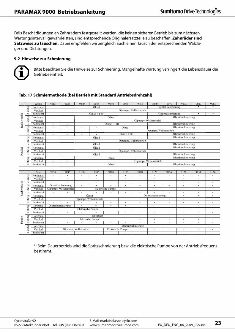
9.2 Hinweise zur Schmierung
Bitte beachten Sie die Hinweise zur Schmierung. Mangelhafte Wartung verringert die Lebensdauer der
Getriebeeinheit.
Tab. 17 Schmiermethode (bei Betrieb mit Standard Antriebsdrehzahl)
*: Beim Dauerbetrieb wird die Spritzschmierung bzw. die elektrische Pumpe von der Antriebsfrequenz
bestimmt.
9015 - 90759080 - 9085
90959105 - 91159015 - 90759080 - 90859015 - 90759080 - 90859030 - 90959100 - 91159030 - 90959100 - 9115
Senkrecht
Senkrecht
9030 - 90859040 - 91159040 - 9115
Senkrecht 9040 - 90859015 - 90959100 - 91059110 - 91159015 - 90959100 - 91059110 - 9115
Senkrecht 9015 - 90859015 - 91159015 - 9115
Senkrecht 9015 - 90859030 - 91159030 - 9115
Senkrecht 9030 - 9085
Horizontal
Horizontal
Horizontal
Horizontal
Bauform Größe
Horizontal
2-s
tufig
3-st
ufig
2-st
ufig
Par
alle
l R
echt
win
klig
3-st
ufig
4-st
ufig
4-st
ufig
Vertikal
Vertikal
Vertikal
Vertikal
Vertikal
Vertikal
1000 1500 1800Antriebsdrehzahl U/min
Horizontal
750
PARAMAX 9000 Betriebsanleitung
E-Mail: [email protected]
www.sumitomodriveeurope.com Tel. +49 (0) 8136 66 0Cyclostraße 92
85229 Markt Indersdorf24 PX_DEU_ENG_06_2009_999345
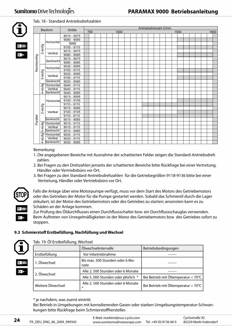
Tab. 18 - Standard Antriebsdrehzahlen
Bemerkung:
1. Die angegebenen Bereiche mit Ausnahme der schattierten Felder zeigen die Standard-Antriebsdreh
zahlen.
2. Bei Fragen zu den Drehzahlen jenseits der schattierten Bereiche bitte Rückfrage bei einer Vertretung,
Händler oder Vertriebsbüro vor Ort.
3. Bei Fragen zu den Standard-Antriebsdrehzahlen für die Getriebegrößen 9118-9136 bitte bei einer
Vertretung, Händler oder Vertriebsbüro vor Ort.
Falls die Anlage über eine Motorpumpe verfügt, muss vor dem Start des Motors des Getriebemotors
oder des Getriebes der Motor für die Pumpe gestartet werden. Sobald das Schmieröl durch die Lager
zirkuliert, ist der Motor des Getriebemotors oder des Getriebes zu starten; ansonsten kann es zu
Schäden an der Anlage kommen.
Zur Prüfung des Öldurchflusses einen Durchflussschalter bzw. ein Durchflussschauglas verwenden.
Beim Auftreten von Unregelmäßigkeiten ist der Motor des Getriebemotors bzw des Getriebes sofort zu
stoppen.
9.3 Schmierstoff Erstbefüllung, Nachfüllung und Wechsel
Tab. 19. Öl Erstbefüllung, Wechsel
Ölwechselintervalle Betriebsbedingungen
Erstbefüllung Vor Inbetriebnahme -------
1. ÖlwechselBis max. 500 Stunden oder 6 Mo-
nate-------
2. Ölwechsel Alle 2. 500 Stunden oder 6 Monate -------
Alle 5. 000 Stunden oder jährlich * Bei Betrieb mit Öltemperatur < 70°C
Weitere Ölwechsel Alle 2. 500 Stunden oder 6 Monate
*Bei Betrieb mit Öltemperatur > 70°C
* je nachdem, was zuerst eintritt.
Bei Betrieb in Umgebungen mit korrodierenden Gasen oder starken Umgebungstemperatur-Schwan-
kungen bitte Rückfrage beim Schmierstoffhersteller.
Senkrecht
Rechtwinklig Parallel
7
1 1
1 4
1 9
2 4
3 0
3 1
4 5
4 4
5 6
6 5
8 7
9 0
126
-
-
-
-
-
-
-
-
-
-
-
-
Größe
9015
9025
9030
9035
9040
9045
9050
9055
9060
9065
9070
9075
9080
9085
9090
9095
9100
9105
9110
9115
9118
9121
9126
9128
9131
9136
Horizontal
Rechtwinklig Parallel
2-stufig
5
7
1 0
1 2
1 6
1 8
2 1
2 8
2 5
2 9
3 7
4 6
5 3
6 7
-
100
-
150
-
200
-
-
-
-
-
-
-
-
16
2 1
2 9
3 6
3 5
4 6
5 6
6 5
8 3
100
115
144
-
-
-
-
-
-
-
-
-
-
-
-
-
-
-
-
3 5
4 3
4 6
5 9
6 8
8 5
107
122
128
174
-
-
-
-
-
-
-
-
-
-
-
-
9
13
16
22
2 9
3 6
3 6
4 7
5 3
6 7
8 4
100
109
137
-
-
-
-
-
-
-
-
-
-
-
-
11
15
20
2 5
3 5
4 3
4 5
5 9
6 8
8 5
106
120
130
176
-
-
-
-
-
-
-
-
-
-
-
-
-
-
20
2 5
3 5
4 3
4 6
5 9
6 9
8 6
108
122
130
175
-
-
-
-
-
-
-
-
-
-
-
-
3-stufig
-
-
10
1 2
1 6
1 8
2 1
2 8
2 9
3 3
4 5
5 2
6 0
7 5
120
155
180
220
250
310
350
460
460
350
510
500
4-stufig2-stufig3-stufig 4-stufig2-stufig3-stufig 4-stufig2-stufig3-stufig 4-stufig2-stufig3-stufig 4-stufig2-stufig3-stufig 4-stufig
-
-
-
-
1 9
2 1
2 4
2 9
3 8
4 3
5 7
6 7
7 3
9 0
150
180
210
255
300
360
390
540
530
460
680
660
5
7
10
1 2
1 6
1 8
2 1
2 8
2 5
2 9
3 8
4 7
5 4
6 8
120
140
170
205
240
290
-
-
-
-
-
-
5
8
10
1 3
1 9
2 1
2 4
2 9
3 3
3 8
4 9
5 9
6 4
8 0
120
155
180
225
260
325
350
470
470
390
550
540
-
-
14
1 7
2 5
2 8
3 2
4 0
3 7
4 2
5 6
6 7
7 3
9 0
150
180
220
260
300
365
390
530
520
450
650
640
Vertikal
Rechtwinklig Parallel
5
7
7
9
1 9
2 3
2 0
2 6
*
*
*
*
*
*
-
-
-
-
-
-
-
-
-
-
-
-
Unit: Liter
-
-
9
1 2
1 8
2 2
2 1
3 0
2 8
3 5
4 6
5 9
6 0
8 0
120
145
170
210
230
290
-
-
-
-
-
-
-
-
-
-
1 8
2 2
2 4
3 4
3 6
4 5
5 4
6 8
6 9
9 4
120
155
180
220
250
315
-
-
-
-
-
-
5
7
9
12
1 8
2 2
2 2
3 1
2 5
3 2
3 9
4 9
5 4
7 1
9 0
120
140
175
200
255
-
-
-
-
-
-
6
8
10
1 4
1 8
2 2
2 5
3 5
2 8
3 5
4 4
5 6
5 7
7 9
9 0
120
140
175
200
255
-
-
-
-
-
-
-
-
10
1 4
1 7
2 1
2 3
3 3
3 2
4 0
5 3
6 7
6 5
8 9
110
140
170
210
240
295
-
-
-
-
-
-
* : Siehe Tablle 33
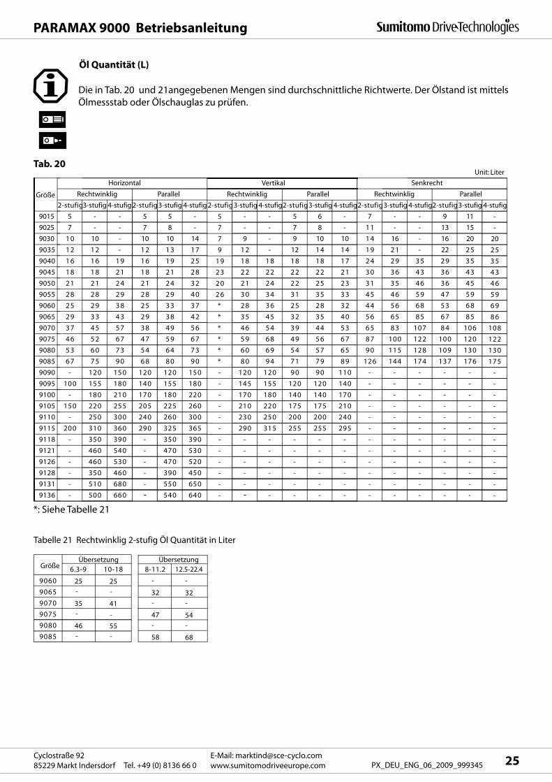
Tabelle 21 Rechtwinklig 2-stufig Öl Quantität in Liter
9060
Größe
9065
9070
9075
9080
9085
6.3-9
25
-
35
-
46
-
10-18
25
-
41
-
55
-
8-11.2
-
32
-
47
-
58
12.5-22.4
-
32
-
54
-
68
Übersetzung Übersetzung
PARAMAX 9000 Betriebsanleitung
25E-Mail: [email protected]
www.sumitomodriveeurope.comTel. +49 (0) 8136 66 0Cyclostraße 92
85229 Markt Indersdorf PX_DEU_ENG_06_2009_999345
Öl Quantität (L)
Die in Tab. 20 und 21angegebenen Mengen sind durchschnittliche Richtwerte. Der Ölstand ist mittels
Ölmessstab oder Ölschauglas zu prüfen.
Tab. 20
*: Siehe Tabelle 21
PARAMAX 9000 Betriebsanleitung
E-Mail: [email protected]
www.sumitomodriveeurope.com Tel. +49 (0) 8136 66 0Cyclostraße 92
85229 Markt Indersdorf26 PX_DEU_ENG_06_2009_999345
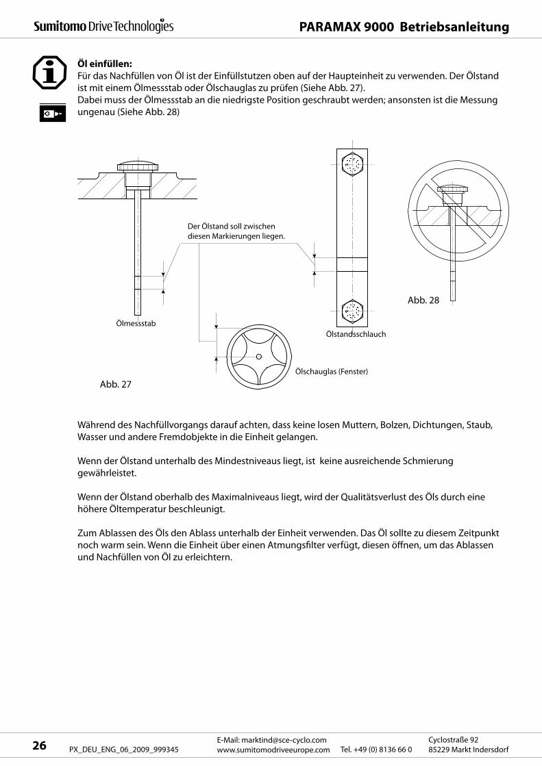
Öl einfüllen:
Für das Nachfüllen von Öl ist der Einfüllstutzen oben auf der Haupteinheit zu verwenden. Der Ölstand
ist mit einem Ölmessstab oder Ölschauglas zu prüfen (Siehe Abb. 27).
Dabei muss der Ölmessstab an die niedrigste Position geschraubt werden; ansonsten ist die Messung
ungenau (Siehe Abb. 28)
Während des Nachfüllvorgangs darauf achten, dass keine losen Muttern, Bolzen, Dichtungen, Staub,
Wasser und andere Fremdobjekte in die Einheit gelangen.
Wenn der Ölstand unterhalb des Mindestniveaus liegt, ist keine ausreichende Schmierung
gewährleistet.
Wenn der Ölstand oberhalb des Maximalniveaus liegt, wird der Qualitätsverlust des Öls durch eine
höhere Öltemperatur beschleunigt.
Zum Ablassen des Öls den Ablass unterhalb der Einheit verwenden. Das Öl sollte zu diesem Zeitpunkt
noch warm sein. Wenn die Einheit über einen Atmungsfilter verfügt, diesen öffnen, um das Ablassen
und Nachfüllen von Öl zu erleichtern.
Ölschauglas (Fenster)
Ölstandsschlauch
Ölmessstab
Abb. 27
Abb. 28
Der Ölstand soll zwischen
diesen Markierungen liegen.
Brand BP SHELL TOTAL
ISO VG68AGMA 2EP
ENERGOLGR-XP-68
ALPHASP68
OPTIGEARBM68
TRIBOL1100/68
GEARCOMPOUNDS
EP68
MEROPAWM68
SPARTANEP68
MOBIL-GEAR
626
OMALA68
CARTEREP68
ISO VG100AGMA 3EP
ENERGOLGR-XP-100
ALPHASP100
OPTIGEARBM100
TRIBOL1100/100
GEARCOMPOUNDS
EP100
MEROPAWM100
SPARTANEP100
MOBIL-GEAR
627
OMALA100
CARTEREP100
ISO VG150AGMA 4EP
ENERGOLGR-XP-150
ALPHASP150
OPTIGEARBM150
TRIBOL1100/150
GEARCOMPOUNDS
EP150
MEROPAWM150
SPARTANEP150
MOBIL-GEAR
629
OMALA150
CARTEREP150
ISO VG220AGMA 5EP
ENERGOLGR-XP-220
ALPHASP220
OPTIGEARBM220
TRIBOL1100/220
GEARCOMPOUNDS
EP220
MEROPAWM220
SPARTANEP220
MOBIL-GEAR
630
OMALA220
CARTEREP220
ISO VG320AGMA 6EP
ENERGOLGR-XP-320
ALPHASP320
OPTIGEARBM320
TRIBOL1100/320
GEARCOMPOUNDS
EP320
MEROPAWM320
SPARTANEP320
MOBIL-GEAR
632
OMALA320
CARTEREP320
ENER-GREASELS EP2
SPHEEROLAP3
Olista Long-time 3EP
TRIBOL3020/
1000-2
DURALITHGREASE 68
MULTI-FAK EP2
BEACONEP2
MOBILUXEP2
ALVANIAEP2
MULTISEP2
EXXON MOBIL
Gea
r Oil
Bearing grease
CASTROL CHEVRON TEXACO
PARAMAX 9000 Betriebsanleitung
27E-Mail: [email protected]
www.sumitomodriveeurope.comTel. +49 (0) 8136 66 0Cyclostraße 92
85229 Markt Indersdorf PX_DEU_ENG_06_2009_999345
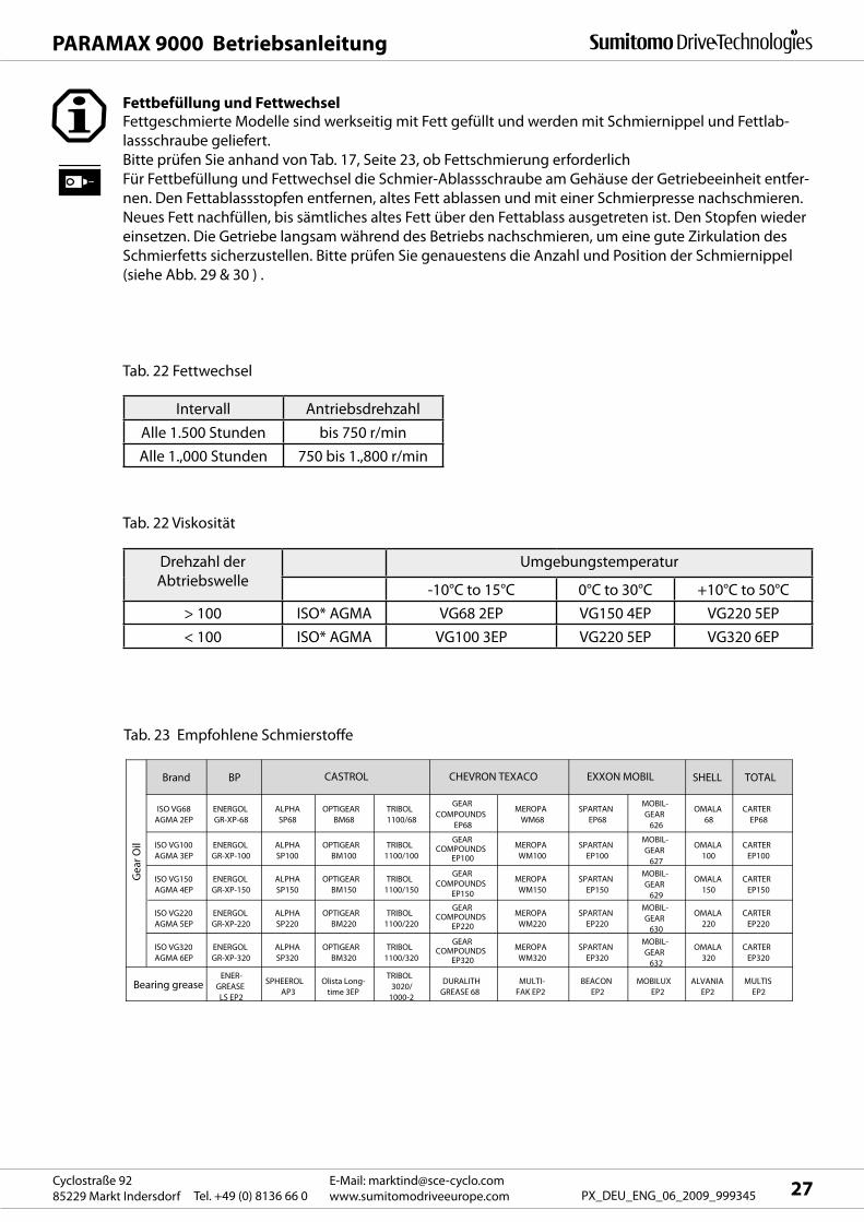
Fettgeschmierte Modelle sind werkseitig mit Fett gefüllt und werden mit Schmiernippel und Fettlab-
lassschraube geliefert.
Bitte prüfen Sie anhand von Tab. 17, Seite 23, ob Fettschmierung erforderlich
Für Fettbefüllung und Fettwechsel die Schmier-Ablassschraube am Gehäuse der Getriebeeinheit entfer-
nen. Den Fettablassstopfen entfernen, altes Fett ablassen und mit einer Schmierpresse nachschmieren.
Neues Fett nachfüllen, bis sämtliches altes Fett über den Fettablass ausgetreten ist. Den Stopfen wieder
einsetzen. Die Getriebe langsam während des Betriebs nachschmieren, um eine gute Zirkulation des
Schmierfetts sicherzustellen. Bitte prüfen Sie genauestens die Anzahl und Position der Schmiernippel
(siehe Abb. 29 & 30 ) .
Tab. 22 Fettwechsel
Tab. 22 Viskosität
Tab. 23 Empfohlene Schmierstoffe
Intervall Antriebsdrehzahl
Alle 1.500 Stunden bis 750 r/min
Alle 1.,000 Stunden 750 bis 1.,800 r/min
Drehzahl der
Abtriebswelle
Umgebungstemperatur
-10°C to 15°C 0°C to 30°C +10°C to 50°C
> 100 ISO* AGMA VG68 2EP VG150 4EP VG220 5EP
< 100 ISO* AGMA VG100 3EP VG220 5EP VG320 6EP
Fettbefüllung und Fettwechsel
PARAMAX 9000 Betriebsanleitung
E-Mail: [email protected]
www.sumitomodriveeurope.com Tel. +49 (0) 8136 66 0Cyclostraße 92
85229 Markt Indersdorf28 PX_DEU_ENG_06_2009_999345
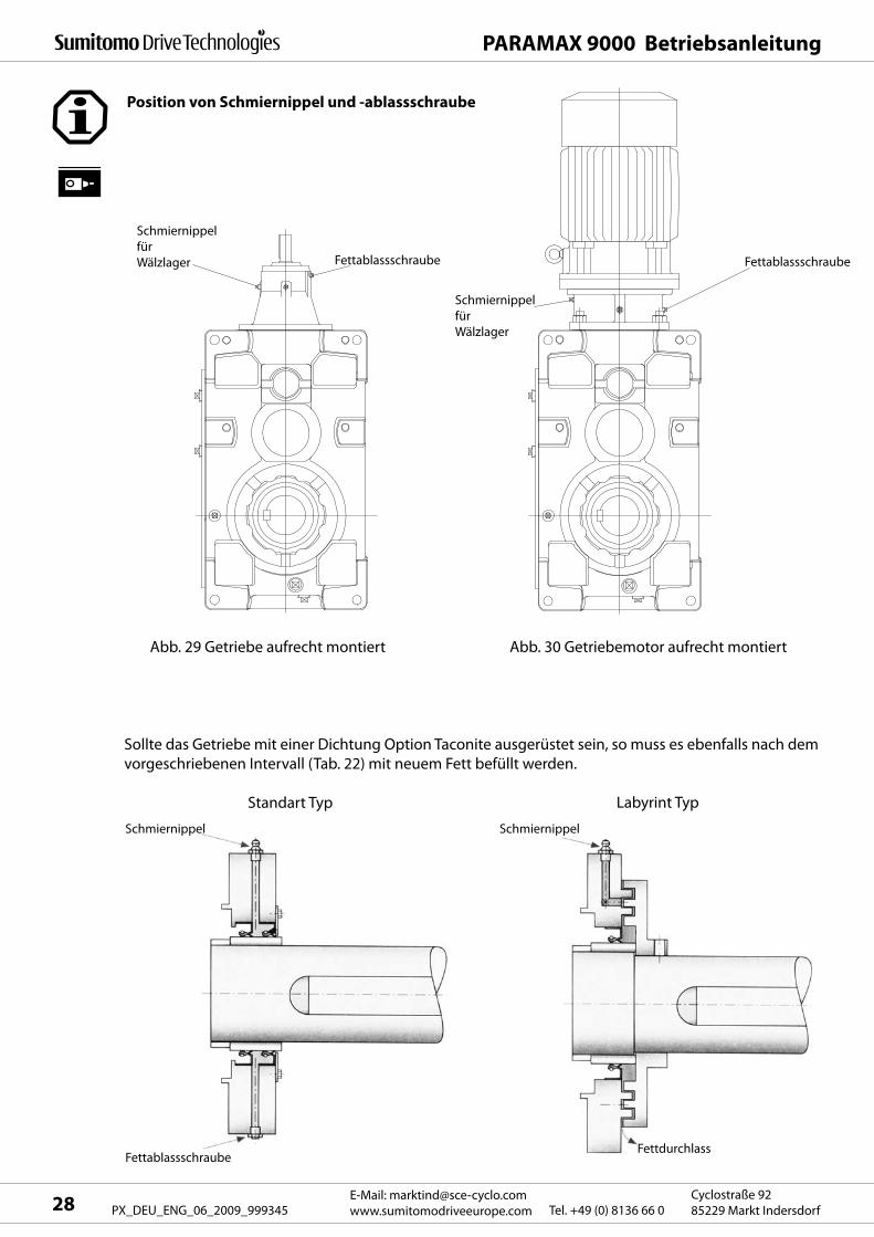
Position von Schmiernippel und -ablassschraube
Schmiernippel
für
Wälzlager
Schmiernippel Schmiernippel
Fettablassschraube
Schmiernippel
für
Wälzlager
Fettablassschraube
Abb. 29 Getriebe aufrecht montiert Abb. 30 Getriebemotor aufrecht montiert
Sollte das Getriebe mit einer Dichtung Option Taconite ausgerüstet sein, so muss es ebenfalls nach dem
vorgeschriebenen Intervall (Tab. 22) mit neuem Fett befüllt werden.
Standart Typ Labyrint Typ
FettdurchlassFettablassschraube
Innerer Durchm.
Äußerer Durchm. Breite 750U/min 900U/min 1000U/min 1200U/min 1500U/min 1800U/min
6314 70 150 35 200 40 8500 7000 6000 5000 3500 25006315 75 160 37 230 45 8500 6500 6000 4500 3500 25006316 80 170 39 260 50 8000 6500 5500 4500 3000 25006317 85 180 41 300 55 7500 6000 5000 4000 3000 20006318 90 190 43 350 60 7000 5500 5000 4000 2500 20006319 95 200 45 400 65 7000 5500 4500 3500 2500 15006320 100 215 47 450 70 6500 5000 4500 3500 2000 15006321 105 225 49 500 75 6000 5000 4000 3000 2000 15006322 110 240 50 550 80 6000 4500 4000 3000 2000 10006324 120 260 55 700 100 5500 4000 3500 2500 1500 10006412 60 150 35 200 40 8500 7000 6000 5000 3500 30006413 65 160 37 230 45 8000 6500 6000 4500 3500 25006414 70 180 42 300 55 8000 6500 5500 4500 3000 2500
NU314 70 150 35 120 40 4000 3500 3000 2500 1500 1000NU315 75 160 37 150 45 4000 3000 3000 2000 1500 1000NU316 80 170 39 200 50 4000 3000 2500 2000 1500 1000NU317 85 180 41 250 55 3500 3000 2500 2000 1500 1000NU318 90 190 43 300 60 3500 2500 2500 2000 1000 1000NU319 95 200 45 350 65 3500 2500 2000 1500 1000NU320 100 215 47 400 70 3000 2500 2000 1500 1000NU321 105 225 49 450 75 3000 2500 2000 1500 1000NU322 110 240 50 500 80 3000 2000 2000 1500 1000NU324 120 260 55 650 100 2500 2000 1500 1000
Schmierintervalle (entsprechend Frequenz U/minErst-
menge (g)
MaßeLager Nr. Nachfüll-
menge (g)
PARAMAX 9000 Betriebsanleitung
29E-Mail: [email protected]
www.sumitomodriveeurope.comTel. +49 (0) 8136 66 0Cyclostraße 92
85229 Markt Indersdorf PX_DEU_ENG_06_2009_999345
9.4 Wartung der Motorlager
Diese Wartungsanweisungen gelten für Sumitomo Motoren.
Falls Brems-, Servo-, Gleichstrom-, Vektor- oder Motoren anderer Hersteller verwendet werden, gelten
die jeweiligen Betriebsanleitungen.
Lagertypen und Wartungsmethoden unterscheiden sich je nach Baugrößen. Hierzu bitte Typenschild
und Lagertyp lt. Tab. 24 beachten.
Tab. 24
Wartung abgedichteter Lager
Da abgedichtete Lager im Voraus mit qualitativ hochwertigem Fett gefüllt werden, muss bei Inbetrieb-
nahme nicht nachgeschmiert werden. Unter normalen Betriebsbedingungen empfehlen wir für eine
kontinuierliche Laufleistung die Lager alle drei bis fünf Jahre bzw. nach 20.000 Betriebsstunden wäh-
rend der Demontage oder der Wartung zu wechseln.
Verwendung von Lagern der CM-Klasse
Verwendung von „MULTEMP SRL (Kyodo Yushi)“
Unter extremen Betriebsbedingungen sind die Lager in einem kürzeren Zeitabstand zu wechseln.
Bei fremdgekühlten Motoren mit einer Lagerlebensdauer des Lüftermotors von 15.000-20.000 Stunden
empfehlen wir den Wechsel des Lüfters alle 15.000 Stunden.
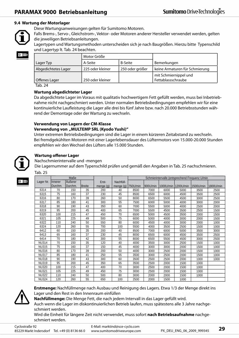
Lager Typ
Motor Größe
BemerkungenA-Seite B-Seite
Abgedichtetes Lager 225 oder kleiner 250 oder größer keine Armaturen für Schmierung
Offenes Lager 250 oder kleiner
mit Schmiernippel und
Fettablassschraube
Wartung offener Lager
Nachschmierintervalle und -mengen
Die Lagernummer auf dem Typenschild prüfen und gemäß den Angaben in Tab. 25 nachschmieren.
Erstmenge: Nachfüllmenge nach Ausbau und Reinigung des Lagers. Etwa 1/3 der Menge direkt ins
Lager und den Rest in den Innenraum einfüllen
Nachfüllmenge: Die Menge Fett, die nach jedem Intervall in das Lager gefüllt wird.
Auch wenn die Lager im diskontinuierlichen Betrieb laufen, muss spätestens alle 3 Jahre nachge-
schmiert werden.
Wird die Einheit für längere Zeit nicht verwendet, muss sofort nach Betriebsaufnahme nachge-
schmiert werden.
Tab. 25
BracketMotor shaft
Open bearing
Bearing cover
Outlet
Grease nipples
PARAMAX 9000 Betriebsanleitung
E-Mail: [email protected]
www.sumitomodriveeurope.com Tel. +49 (0) 8136 66 0Cyclostraße 92
85229 Markt Indersdorf30 PX_DEU_ENG_06_2009_999345
Empfohlene Schmierstoffe - Fett
Keine Fettsorten außer den in Tab. 26 aufgeführten verwenden!
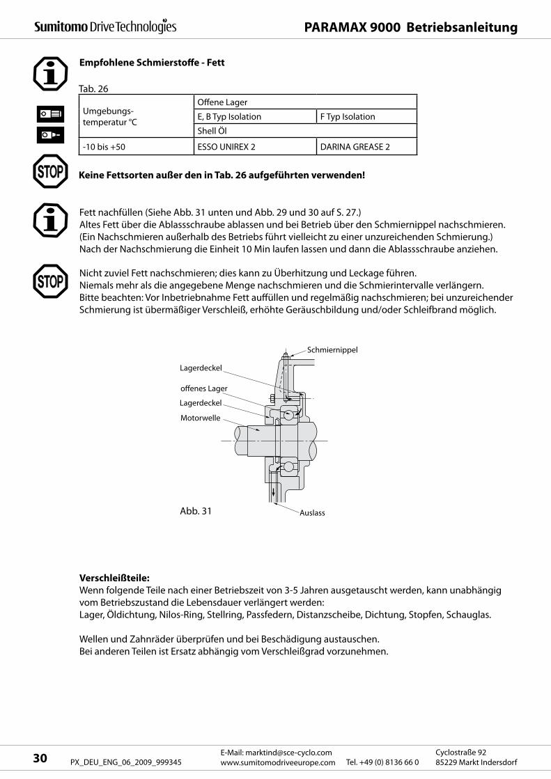
Fett nachfüllen (Siehe Abb. 31 unten und Abb. 29 und 30 auf S. 27.)
Altes Fett über die Ablassschraube ablassen und bei Betrieb über den Schmiernippel nachschmieren.
(Ein Nachschmieren außerhalb des Betriebs führt vielleicht zu einer unzureichenden Schmierung.)
Nach der Nachschmierung die Einheit 10 Min laufen lassen und dann die Ablassschraube anziehen.
Nicht zuviel Fett nachschmieren; dies kann zu Überhitzung und Leckage führen.
Niemals mehr als die angegebene Menge nachschmieren und die Schmierintervalle verlängern.
Bitte beachten: Vor Inbetriebnahme Fett auffüllen und regelmäßig nachschmieren; bei unzureichender
Schmierung ist übermäßiger Verschleiß, erhöhte Geräuschbildung und/oder Schleifbrand möglich.
Verschleißteile:
Wenn folgende Teile nach einer Betriebszeit von 3-5 Jahren ausgetauscht werden, kann unabhängig
vom Betriebszustand die Lebensdauer verlängert werden:
Lager, Öldichtung, Nilos-Ring, Stellring, Passfedern, Distanzscheibe, Dichtung, Stopfen, Schauglas.
Wellen und Zahnräder überprüfen und bei Beschädigung austauschen.
Bei anderen Teilen ist Ersatz abhängig vom Verschleißgrad vorzunehmen.
Umgebungs-
temperatur °C
Offene Lager
E, B Typ Isolation F Typ Isolation
Shell Öl
-10 bis +50 ESSO UNIREX 2 DARINA GREASE 2
Tab. 26
Schmiernippel
Lagerdeckel
offenes Lager
Lagerdeckel
Motorwelle
Abb. 31 Auslass
PARAMAX 9000 Betriebsanleitung
31E-Mail: [email protected]
www.sumitomodriveeurope.comTel. +49 (0) 8136 66 0Cyclostraße 92
85229 Markt Indersdorf PX_DEU_ENG_06_2009_999345
10. Demontage / Montage
Reparatur, Demontage und Montage dürfen nur durch ausgebildetes technisches Fachpersonal
durchgeführt werden; andernfalls besteht die Gefahr von Schäden an der Maschine.
Niemals in die Passfedernut oder andere Teile mit scharfen Kanten fassen: Verletzungsgefahr.
Die Demontage nur an staubfreien, trockenen Orten durchführen.
Zubehör wie Schrauben sind in einem Kasten aufzubewahren, um sie nicht zu verlieren.
Teile sind sorgfältig zu behandeln, um Beschädigungen zu vermeiden.
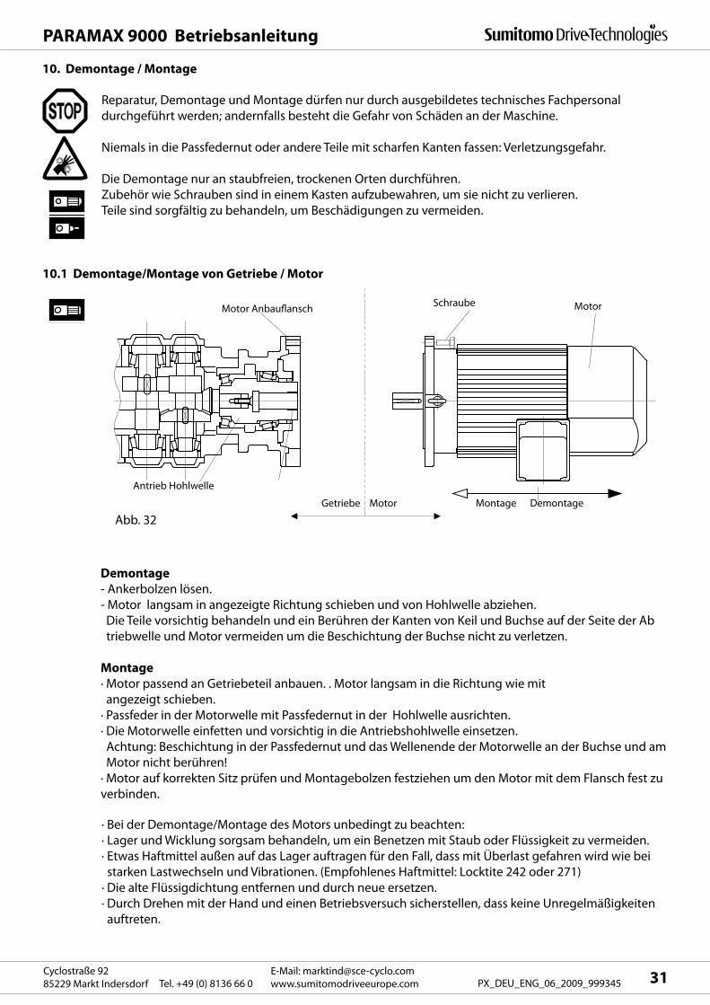
10.1 Demontage/Montage von Getriebe / Motor
Motor AnbauflanschSchraube Motor
Montage DemontageGetriebe Motor
Antrieb Hohlwelle
Demontage
- Ankerbolzen lösen.
- Motor langsam in angezeigte Richtung schieben und von Hohlwelle abziehen.
Die Teile vorsichtig behandeln und ein Berühren der Kanten von Keil und Buchse auf der Seite der Ab
triebwelle und Motor vermeiden um die Beschichtung der Buchse nicht zu verletzen.
Montage
· Motor passend an Getriebeteil anbauen. . Motor langsam in die Richtung wie mit
angezeigt schieben.
· Passfeder in der Motorwelle mit Passfedernut in der Hohlwelle ausrichten.
· Die Motorwelle einfetten und vorsichtig in die Antriebshohlwelle einsetzen.
Achtung: Beschichtung in der Passfedernut und das Wellenende der Motorwelle an der Buchse und am
Motor nicht berühren!
· Motor auf korrekten Sitz prüfen und Montagebolzen festziehen um den Motor mit dem Flansch fest zu
verbinden.
· Bei der Demontage/Montage des Motors unbedingt zu beachten:
· Lager und Wicklung sorgsam behandeln, um ein Benetzen mit Staub oder Flüssigkeit zu vermeiden.
· Etwas Haftmittel außen auf das Lager auftragen für den Fall, dass mit Überlast gefahren wird wie bei
starken Lastwechseln und Vibrationen. (Empfohlenes Haftmittel: Locktite 242 oder 271)
· Die alte Flüssigdichtung entfernen und durch neue ersetzen.
· Durch Drehen mit der Hand und einen Betriebsversuch sicherstellen, dass keine Unregelmäßigkeiten
auftreten.
Abb. 32
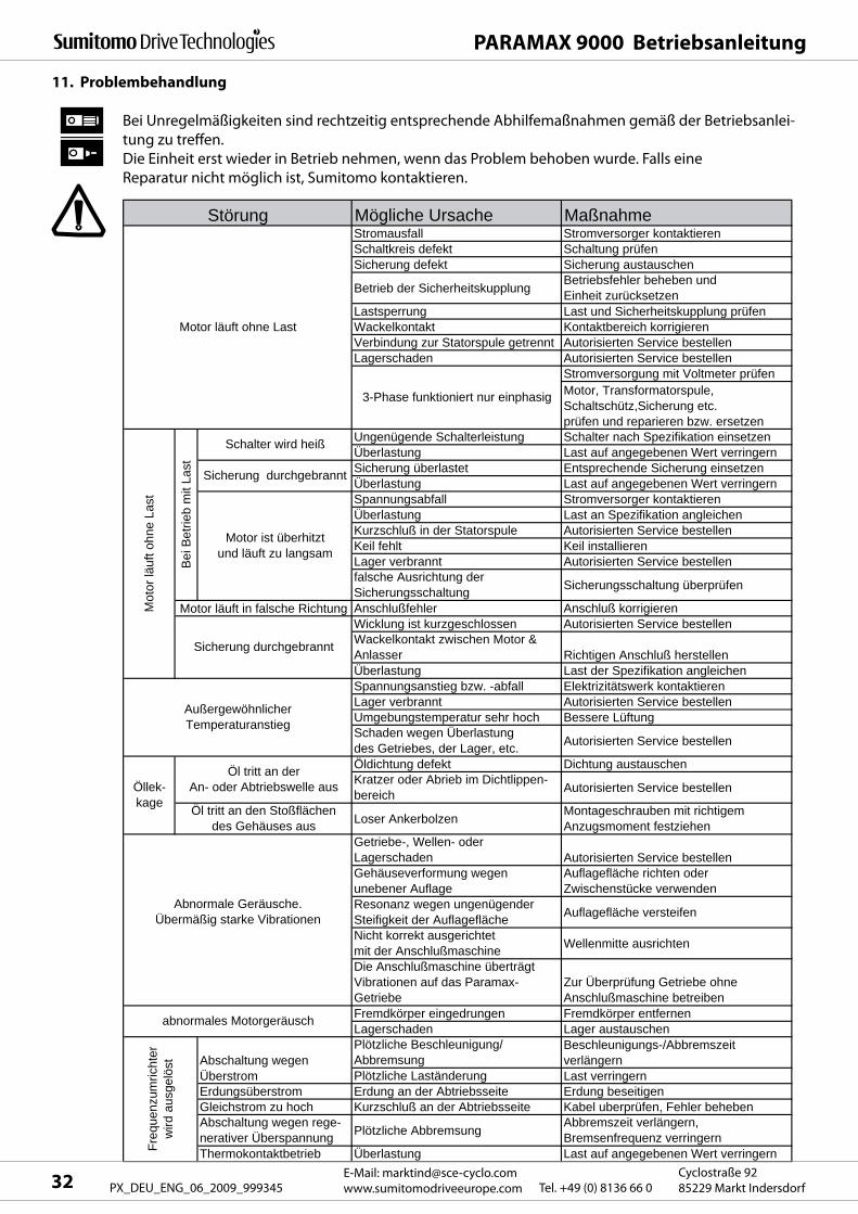
Mögliche Ursache MaßnahmeStromausfall Stromversorger kontaktierenSchaltkreis defekt Schaltung prüfenSicherung defekt Sicherung austauschen
Betrieb der Sicherheitskupplung Betriebsfehler beheben und Einheit zurücksetzen
Lastsperrung Last und Sicherheitskupplung prüfenWackelkontakt Kontaktbereich korrigierenVerbindung zur Statorspule getrennt Autorisierten Service bestellenLagerschaden Autorisierten Service bestellen
Stromversorgung mit Voltmeter prüfen
Ungenügende Schalterleistung Schalter nach Spezifikation einsetzenÜberlastung Last auf angegebenen Wert verringernSicherung überlastet Entsprechende Sicherung einsetzenÜberlastung Last auf angegebenen Wert verringernSpannungsabfall Stromversorger kontaktierenÜberlastung Last an Spezifikation angleichenKurzschluß in der Statorspule Autorisierten Service bestellenKeil fehlt Keil installierenLager verbrannt Autorisierten Service bestellenfalsche Ausrichtung der Sicherungsschaltung Sicherungsschaltung überprüfen
Anschlußfehler Anschluß korrigierenWicklung ist kurzgeschlossen Autorisierten Service bestellenWackelkontakt zwischen Motor & Anlasser Richtigen Anschluß herstellenÜberlastung Last der Spezifikation angleichenSpannungsanstieg bzw. -abfall Elektrizitätswerk kontaktierenLager verbrannt Autorisierten Service bestellenUmgebungstemperatur sehr hoch Bessere Lüftung Schaden wegen Überlastung des Getriebes, der Lager, etc. Autorisierten Service bestellen
Öldichtung defekt Dichtung austauschenKratzer oder Abrieb im Dichtlippen-bereich Autorisierten Service bestellen
Loser Ankerbolzen Montageschrauben mit richtigem Anzugsmoment festziehen
Getriebe-, Wellen- oder Lagerschaden Autorisierten Service bestellenGehäuseverformung wegen unebener Auflage
Auflagefläche richten oder Zwischenstücke verwenden
Resonanz wegen ungenügenderSteifigkeit der Auflagefläche Auflagefläche versteifen
Nicht korrekt ausgerichtet mit der Anschlußmaschine Wellenmitte ausrichten
Die Anschlußmaschine überträgt Vibrationen auf das Paramax-Getriebe
Zur Überprüfung Getriebe ohne Anschlußmaschine betreiben
Fremdkörper eingedrungen Fremdkörper entfernenLagerschaden Lager austauschenPlötzliche Beschleunigung/Abbremsung
Beschleunigungs-/Abbremszeit verlängern
Plötzliche Laständerung Last verringernErdungsüberstrom Erdung an der Abtriebsseite Erdung beseitigenGleichstrom zu hoch Kurzschluß an der Abtriebsseite Kabel uberprüfen, Fehler behebenAbschaltung wegen rege-nerativer Überspannung Plötzliche Abbremsung Abbremszeit verlängern,
Bremsenfrequenz verringernThermokontaktbetrieb Überlastung Last auf angegebenen Wert verringern
Motor, Transformatorspule, Schaltschütz,Sicherung etc. prüfen und reparieren bzw. ersetzen
Sicherung durchgebrannt
Schalter wird heiß
Sicherung durchgebrannt
Motor ist überhitzt und läuft zu langsam
Störung
Öl tritt an den Stoßflächen des Gehäuses aus
Außergewöhnlicher Temperaturanstieg
3-Phase funktioniert nur einphasig
Öl tritt an der An- oder Abtriebswelle ausÖllek-
kage
Motor läuft ohne Last
Bei
Bet
rieb
mit
Last
Mot
or lä
uft o
hne
Last
Motor läuft in falsche Richtung
Abnormale Geräusche.Übermäßig starke Vibrationen
abnormales Motorgeräusch
Abschaltung wegen Überstrom
Freq
uenz
umric
hter
w
ird a
usge
löst
PARAMAX 9000 Betriebsanleitung
E-Mail: [email protected]
www.sumitomodriveeurope.com Tel. +49 (0) 8136 66 0Cyclostraße 92
85229 Markt Indersdorf32 PX_DEU_ENG_06_2009_999345
11. Problembehandlung
Bei Unregelmäßigkeiten sind rechtzeitig entsprechende Abhilfemaßnahmen gemäß der Betriebsanlei-
tung zu treffen.
Die Einheit erst wieder in Betrieb nehmen, wenn das Problem behoben wurde. Falls eine
Reparatur nicht möglich ist, Sumitomo kontaktieren.
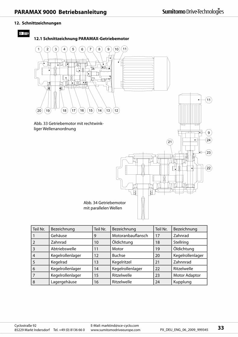
21
9
24
23
22
11
1 2 3 4 5 6 7 8 9 10 11
19 18 17 16 15 14 1320 12
PARAMAX 9000 Betriebsanleitung
33E-Mail: [email protected]
www.sumitomodriveeurope.comTel. +49 (0) 8136 66 0Cyclostraße 92
85229 Markt Indersdorf PX_DEU_ENG_06_2009_999345
12. Schnittzeichnungen
12.1 Schnittzeichnung PARAMAX-Getriebemotor
Abb. 33 Getriebemotor mit rechtwink-
liger Wellenanordnung
Abb. 34 Getriebemotor
mit parallelen Wellen
Teil Nr. Bezeichnung Teil Nr. Bezeichnung Teil Nr. Bezeichnung
1 Gehäuse 9 Motoranbauflansch 17 Zahnrad
2 Zahnrad 10 Öldichtung 18 Stellring
3 Abtriebswelle 11 Motor 19 Öldichtung
4 Kegelrollenlager 12 Buchse 20 Kegelrollenlager
5 Kegelrad 13 Kegelritzel 21 Zahnnrad
6 Kegelrollenlager 14 Kegelrollenlager 22 Ritzelwelle
7 Kegelrollenlager 15 Ritzelwelle 23 Motor Adaptor
8 Lagergehäuse 16 Ritzelwelle 24 Kupplung
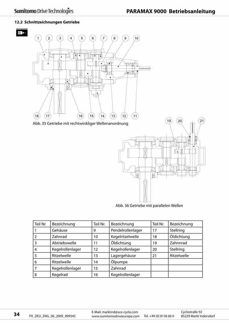
212019
8 9 107654321
13 12 111415161718
PARAMAX 9000 Betriebsanleitung
E-Mail: [email protected]
www.sumitomodriveeurope.com Tel. +49 (0) 8136 66 0Cyclostraße 92
85229 Markt Indersdorf34 PX_DEU_ENG_06_2009_999345
12.2 Schnittzeichnungen Getriebe
Abb. 35 Getriebe mit rechtwinkliger Wellenanordnung
Abb. 36 Getriebe mit parallelen Wellen
Teil Nr. Bezeichnung Teil Nr. Bezeichnung Teil Nr. Bezeichnung
1 Gehäuse 9 Pendelrollenlager 17 Stellring
2 Zahnrad 10 Kegelritzelwelle 18 Öldichtung
3 Abtriebswelle 11 Öldichtung 19 Zahnnrad
4 Kegelrollenlager 12 Kegelrollenlager 20 Stellring
5 Ritzelwelle 13 Lagergehäuse 21 Ritzelwelle
6 Ritzelwelle 14 Ölpumpe
7 Kegelrollenlager 15 Zahnrad
8 Kegelrad 16 Kegelrollenlager
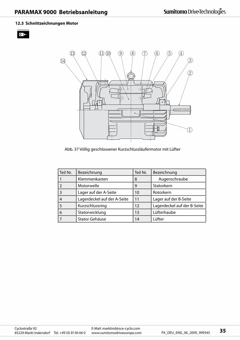
PARAMAX 9000 Betriebsanleitung
35E-Mail: [email protected]
www.sumitomodriveeurope.comTel. +49 (0) 8136 66 0Cyclostraße 92
85229 Markt Indersdorf PX_DEU_ENG_06_2009_999345
Teil Nr. Bezeichnung Teil Nr. Bezeichnung
1 Klemmenkasten 8 Augenschraube
2 Motorwelle 9 Statorkern
3 Lager auf der A-Seite 10 Rotorkern
4 Lagerdeckel auf der A-Seite 11 Lager auf der B-Seite
5 Kurzschlussring 12 Lagerdeckel auf der B-Seite
6 Statorwicklung 13 Lüfterhaube
7 Stator Gehäuse 14 Lüfter
12.3 Schnittzeichnungen Motor
Abb. 37 Völlig geschlossener Kurzschlussläufermotor mit Lüfter

PARAMAX 9000 Betriebsanleitung
E-Mail: [email protected]
www.sumitomodriveeurope.com Tel. +49 (0) 8136 66 0Cyclostraße 92
85229 Markt Indersdorf36 PX_DEU_ENG_06_2009_999345
13. Lage Öleinfüllstutzen und Ablassschraube
Horizontal
Vertikal
Aufrecht
Abb.38 Ablassschraube
Öleinfüllstutzen
Öleinfüllstutzen (parallel)Öleinfüllstutzen (rechtwinklig)
Abb.40
Abb.39
Ablassschraube (9090-9115)
Öleinfüllstutzen (9060-9136)Öleinfüllstutzen (9015-9055)
Ablassschraube (9015-9085)
Ablassschraube

PARAMAX 9000 Betriebsanleitung
37E-Mail: [email protected]
www.sumitomodriveeurope.comTel. +49 (0) 8136 66 0Cyclostraße 92
85229 Markt Indersdorf PX_DEU_ENG_06_2009_999345
Explosionsfähige Gasgemische oder Staubkonzentrationen können in Verbindung mit heißen, span-
nungsführenden und bewegten Teilen des Getriebes zu schweren Sach- und Personenschäden bis hin
zu tödliche Verletzungen führen.
Standardeinheiten der PARAMAX -Getriebe und Getriebemotoren dürfen nicht in einem Bereich ver-
wendet werden, in dem Explosionsgefahr besteht.
Unter solchen Bedingungen sind eigens explosionsgeschützte Getriebe, bzw. Getriebemotoren einzu-
setzen.
Ein für ATEX zertifiziertes Getriebe, bzw. ein für ATEX zertifizierter Getriebemotor ist werkseitig immer
mit einer ATEX -Kennzeichnung versehen. Die ATEX -Kennzeichnung befindet sich auf dem Typenschild
(Siehe Kapitel 3.1).
Montage, Anschluss, Inbetriebnahme sowie Wartungs- und Reparaturarbeiten am Getriebe/ Getrie-
bemotor sowie an der elektrischen Zusatzausstattung dürfen nur durch qualifiziertes Fachpersonal
erfolgen, unter Berücksichtigung:
- dieser Anleitung
- der Warn- und Hinweisschilder am Getriebe / Getriebemotor
- aller anderen zum Antrieb gehörenden Projektierungsunterlagen und Schaltbilder
- der anlagenspezifischen Bestimmungen und Erfordernisse
- der nationalen/regionalen gültigen Normen und Vorschriften (Explosionsschutz, Sicherheit,
Unfallverhütung)
-Staubablagerungen dürfen eine Dicke von 1 mm nicht überschreiten und sind gegebenenfalls zu ent
fernen.
- Die kundenseitige Einbausituation darf den Wärmeabfluss des Getriebes, welcher durch Konvektion
und Wärmeleitung erfolgt, nicht behindern.
- Der Betrieb mit Überlast ist nicht zulässig.
- Ein Wärmeeintrag von außen in das Getriebe ist nicht zulässig.
- Die Öltemperatur darf max. 850C nicht übersteigen.
- Die Antriebsdrehzahl darf max. 1800 1/min nicht übersteigen.
- Alle elektrischen und mechanischen, am Getriebe angebauten Komponenten, müssen ein
eigenes ATEX Zertifikat aufweisen.
Da der Umrichter selbst nicht explosionsgeschützt ist, dürfen auch explosionsgeschützte, umrichterbe-
triebene Motoren nur in einer von explosionsfähigen Gasgemischen oder Staubkonzentrationen freien
Umgebung aufgestellt werden. Ansonsten kann es zu elektrischen Schlägen, Verletzungen, Explosionen
oder Schäden an der Ausrüstung kommen.
14.1 Sicherheitshinweise zum Einsatz im ATEX Bereich
14 Besondere Hinweise für ATEX zugelassene PARAMAX Getriebe und Getriebemotoren
Elektrische Installation eines explosionsgeschützten Motors (ATEX)
Die Zuleitung eines explosionsgeschützten Motors muss mit den werkseitigen elektrischen Codes,
Anschlussbedingungen und der Explosionsverordnung sowie der Betriebsanleitung übereinstimmen;
ansonsten besteht die Gefahr elektrischer Schläge, von Verletzungen, Explosion, Brandgefahr oder von
Schäden an der Ausrüstung.
Bei dem elektrischen Anschluss ist den werkseitigen elektrischen Bezeichnungen, den Anschlussbe-
dingungen und der Explosionsschutzverordnung Folge zu leisten; ansonsten besteht die Gefahr von
Verbrennungen, elektrischer Schläge, von Verletzungen und Brandgefahr.
Bei explosionsgeschützten Motoren muss einen Überlastungsschutz verwendet werden, der die
Einheit nach einem bestimmten Zeitintervall abschaltet, wenn der Motor gesperrt ist.
Wird für einen explosionsgeschützten Motor ein Umrichter verwendet, muss pro Motor ein Umrich-
ter eingesetzt werden. Es sind nur zugelassene Umrichter zu verwenden.
Bei der Messung des Isolationswiderstands bei einem explosionsgeschützten Motor muss sicherge-
stellt werden, dass die Umgebung frei ist von Gas, Dämpfen oder anderen explosiven Substanzen,
damit eine Explosion oder Entzündung ausgeschlossen werden kann.
14.1 Sicherheitshinweise zum Einsatz im ATEX Bereich

PARAMAX 9000 Betriebsanleitung
E-Mail: [email protected]
www.sumitomodriveeurope.com Tel. +49 (0) 8136 66 0Cyclostraße 92
85229 Markt Indersdorf38 PX_DEU_ENG_06_2009_999345
- Entsprechen die Angaben auf dem Typenschild des Getriebes bzw des Getriebemotors dem vor Ort
geforderten ATEX-Einsatzbereich?
- Ist das Typenschild mit den korrekten Angaben versehen?
- Ist der Antrieb unbeschädigt (auf evtl. Transport- oder Lagerschäden überprüfen)?
- Ist eine ungehinderte Kühlluftzufuhr gewährleistet? Wird keine warme Abluft anderer Aggregate
angesaugt? Die Kühlluft darf eine Temperatur von 40°C nicht überschreiten.
- Sind alle An- und Abtriebselemente, sowie alle elektrischen Teile ATEX-zugelassen, und ebenbfalls mit
der korrekten Kennzeichnung versehen?
Das Getriebe ist bei der ersten Inbetriebnahme ohne Last einzuschalten. Läuft es ruhig und ohne
abnormale Geräusche, wird das Getriebe mit der Arbeitsmaschine belastet.
Nach ca. 3 Stunden die Oberflächentemperatur messen. Den maximal zulässigen Differenzwert gegen-
über der Umgebungstemperatur prüfen. Bei einem Wert über dem für die jeweiligen Type angegebe-
nen, ist die Anlage sofort stilllzuegen und Rücksprache mit Sumitomo nehmen.
Bei Anwendungen im ATEX–Bereich werden die Getriebe PARAMAX ab Werk so ausgelegt, dass die
Öltemperatur 850C unter keinen Umständen übersteigt. Dies ist durch den Betreiber in der jeweiligen
Applikation ebenfalls sicherzustellen.
Eine Überprüfung der Öltemperatur erfolgt in der Anlage immer unter Volllast.
14.2 Checkliste für ATEX zugelassene Getriebe und Getriebemotoren vor Inbetriebnahme
Ist das bei Getrieben in ATEX Ausführung angebaute PT100 Temperaturelement korrekt angeschlossen?
Bei Sensoren und passiven Bauelementen ist ein Trennverstärker vorzusehen.
Dabei ist die komplette Verkabelung mit Anschlussbauteilen in hellblauer Farbe auszuführen.
ATEX -Kennzeichnung ATEX -Klassifizierung
Typenschild PARAMAX mit ATEX -Kennzeichnung
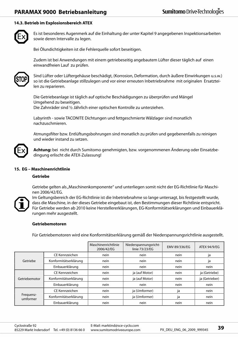
PARAMAX 9000 Betriebsanleitung
39E-Mail: [email protected]
www.sumitomodriveeurope.comTel. +49 (0) 8136 66 0Cyclostraße 92
85229 Markt Indersdorf PX_DEU_ENG_06_2009_999345
Es ist besonderes Augenmerk auf die Einhaltung der unter Kapitel 9 angegebenen Inspektionsarbeiten
sowie deren Intervalle zu legen.
Bei Ölundichtigkeiten ist die Fehlerquelle sofort beseitigen.
Zudem ist bei Anwendungen mit einem getriebeseitig angebautem Lüfter dieser täglich auf einen
einwandfreien Lauf zu prüfen.
Sind Lüfter oder Lüftergehäuse beschädigt, (Korrosion, Deformation, durch äußere Einwirkungen u.s.w.)
so ist die Getriebeanlage stillzulegen und vor einer erneuten Inbetriebnahme mit originalen Ersatztei-
len zu reparieren.
Die Getriebeanlage ist täglich auf optische Beschädigungen zu überprüfen und Mängel
Umgehend zu beseitigen.
Die Zahnräder sind ½ Jährlich einer optischen Kontrolle zu unterziehen.
Labyrinth - sowie TACONITE Dichtungen und fettgeschmierte Wälzlager sind monatlich
nachzuschmieren.
Atmungsfilter bzw. Entlüftungsbohrungen sind monatlich zu prüfen und gegebenenfalls zu reinigen
und wieder instand zu setzen.
Achtung: bei nicht durch Sumitomo genehmigten, bzw. vorgenommenen Änderung oder Einsatzbe-
dingung erlischt die ATEX-Zulassung!
14.3. Betrieb im Explosionsbereich ATEX
Getriebe
Getriebe gelten als „Maschinenkomponente“ und unterliegen somit nicht der EG-Richtlinie für Maschi-
nen 2006/42/EG.
Im Geltungsbereich der EG-Richtlinie ist die Inbetriebnahme so lange untersagt, bis festgestellt wurde,
dass die Maschine, in der dieses Getriebe eingebaut ist, den Bestimmungen dieser Richtlinie entspricht.
Für Getriebe werden ab 2010 keine Herstellererklärungen, EG-Konformitätserklärungen und Einbauerklä-
rungen mehr ausgestellt.
Getriebemotoren
Für Getriebemotoren wird eine Konformitätserklärung gemäß der Niederspannungsrichtlinie ausgestellt.
Maschinenrichtlinie
2006/42/EG
Niederspannungsricht-
linie 73/23/EGEMV 89/336/EG ATEX 94/9/EG
Getriebe
CE Kennzeichen nein nein nein ja
Konformitätserklärung nein nein nein ja
Einbauerklärung nein nein nein nein
Getriebemotor
CE Kennzeichen nein ja (auf Motor) nein ja (Getriebe)
Konformitätserklärung nein ja (auf Motor) nein ja (Getrieber)
Einbauerklärung nein nein nein nein
Frequenz-
umformer
CE Kennzeichen nein ja (Umformer) ja nein
Konformitätserklärung nein ja (Umformer) ja nein
Einbauerklärung nein nein nein nein
15. EG – Maschinenrichtlinie

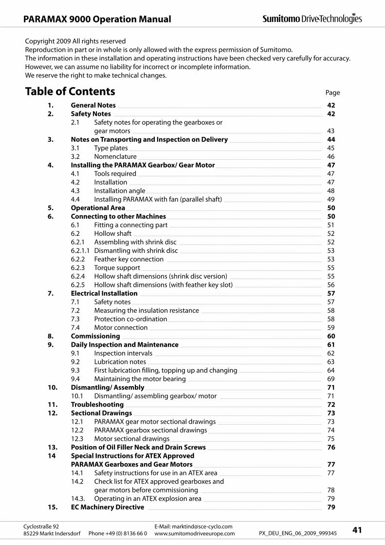
41E-Mail: [email protected]
www.sumitomodriveeurope.comPhone +49 (0) 8136 66 0Cyclostraße 92
85229 Markt Indersdorf PX_DEU_ENG_06_2009_999345
PARAMAX 9000 Operation Manual
Copyright 2009 All rights reserved
Reproduction in part or in whole is only allowed with the express permission of Sumitomo.
The information in these installation and operating instructions have been checked very carefully for accuracy.
However, we can assume no liability for incorrect or incomplete information.
We reserve the right to make technical changes.
1. General Notes 42
2. Safety Notes 42
2.1 Safety notes for operating the gearboxes or
gear motors 43
3. Notes on Transporting and Inspection on Delivery 44
3.1 Type plates 45
3.2 Nomenclature 46
4. Installing the PARAMAX Gearbox/ Gear Motor 47
4.1 Tools required 47
4.2 Installation 47
4.3 Installation angle 48
4.4 Installing PARAMAX with fan (parallel shaft) 49
5. Operational Area 50
6. Connecting to other Machines 50
6.1 Fitting a connecting part 51
6.2 Hollow shaft 52
6.2.1 Assembling with shrink disc 52
6.2.1.1 Dismantling with shrink disc 53
6.2.2 Feather key connection 53
6.2.3 Torque support 55
6.2.4 Hollow shaft dimensions (shrink disc version) 55
6.2.5 Hollow shaft dimensions (with feather key slot) 56
7. Electrical Installation 57
7.1 Safety notes 57
7.2 Measuring the insulation resistance 58
7.3 Protection co-ordination 58
7.4 Motor connection 59
8. Commissioning 60
9. Daily Inspection and Maintenance 61
9.1 Inspection intervals 62
9.2 Lubrication notes 63
9.3 First lubrication filling, topping up and changing 64
9.4 Maintaining the motor bearing 69
10. Dismantling/ Assembly 71
10.1 Dismantling/ assembling gearbox/ motor 71
11. Troubleshooting 72
12. Sectional Drawings 73
12.1 PARAMAX gear motor sectional drawings 73
12.2 PARAMAX gearbox sectional drawings 74
12.3 Motor sectional drawings 75
13. Position of Oil Filler Neck and Drain Screws 76
14 Special Instructions for ATEX Approved
PARAMAX Gearboxes and Gear Motors 77
14.1 Safety instructions for use in an ATEX area 77
14.2 Check list for ATEX approved gearboxes and
gear motors before commissioning 78
14.3. Operating in an ATEX explosion area 79
15. EC Machinery Directive 79
Table of Contents Page
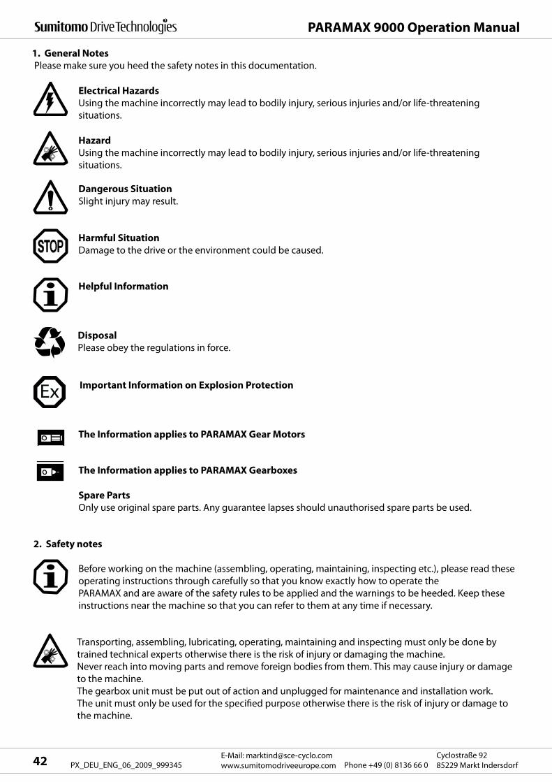
PARAMAX 9000 Operation Manual
E-Mail: [email protected]
www.sumitomodriveeurope.com Phone +49 (0) 8136 66 0Cyclostraße 92
85229 Markt Indersdorf42 PX_DEU_ENG_06_2009_999345
1. General Notes
Please make sure you heed the safety notes in this documentation.
Electrical Hazards
Using the machine incorrectly may lead to bodily injury, serious injuries and/or life-threatening
situations.
Hazard
Using the machine incorrectly may lead to bodily injury, serious injuries and/or life-threatening
situations.
Dangerous Situation
Slight injury may result.
Harmful Situation
Damage to the drive or the environment could be caused.
Helpful Information
Disposal
Please obey the regulations in force.
Important Information on Explosion Protection
The Information applies to PARAMAX Gear Motors
The Information applies to PARAMAX Gearboxes
2. Safety notes
Before working on the machine (assembling, operating, maintaining, inspecting etc.), please read these
operating instructions through carefully so that you know exactly how to operate the
PARAMAX and are aware of the safety rules to be applied and the warnings to be heeded. Keep these
instructions near the machine so that you can refer to them at any time if necessary.
Transporting, assembling, lubricating, operating, maintaining and inspecting must only be done by
trained technical experts otherwise there is the risk of injury or damaging the machine.
Never reach into moving parts and remove foreign bodies from them. This may cause injury or damage
to the machine.
The gearbox unit must be put out of action and unplugged for maintenance and installation work.
The unit must only be used for the specified purpose otherwise there is the risk of injury or damage to
the machine.
Spare Parts
Only use original spare parts. Any guarantee lapses should unauthorised spare parts be used.

43E-Mail: [email protected]
www.sumitomodriveeurope.comPhone +49 (0) 8136 66 0Cyclostraße 92
85229 Markt Indersdorf PX_DEU_ENG_06_2009_999345
PARAMAX 9000 Operation Manual
2.1 Safety notes for Operating Gearboxes or Gear Motors
A drive motor connected to the gearbox may only be operated after ensuring that the information on
the rating plate matches the documentation supplied (drawings, parts lists etc.).
- The drive must not be damaged in any way.
- The lubricants provided must be suitable and if necessary prepared for the environmental conditions.
A motor connected to the gearbox may only be operated on the frequency inverter if the information
on the gearbox rating plate is obeyed. The gearboxes are intended for commercial
equipment and must only be used in accordance with the information in the technical documentation
and the information on the rating plate. They comply with the standards and regulations in force and
meet the requirements of Directive 94/9EG.
You will find more important information on this in Section 7.1.
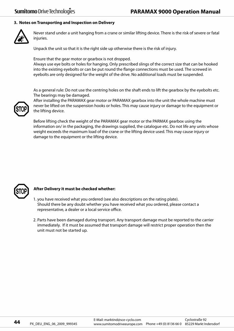
PARAMAX 9000 Operation Manual
E-Mail: [email protected]
www.sumitomodriveeurope.com Phone +49 (0) 8136 66 0Cyclostraße 92
85229 Markt Indersdorf44 PX_DEU_ENG_06_2009_999345
3. Notes on Transporting and Inspection on Delivery
Never stand under a unit hanging from a crane or similar lifting device. There is the risk of severe or fatal
injuries.
Unpack the unit so that it is the right side up otherwise there is the risk of injury.
Ensure that the gear motor or gearbox is not dropped.
Always use eye bolts or holes for hanging. Only prescribed slings of the correct size that can be hooked
into the existing eyebolts or can be put round the flange connections must be used. The screwed in
eyebolts are only designed for the weight of the drive. No additional loads must be suspended.
As a general rule: Do not use the centring holes on the shaft ends to lift the gearbox by the eyebolts etc.
The bearings may be damaged.
After installing the PARAMAX gear motor or PARAMAX gearbox into the unit the whole machine must
never be lifted on the suspension hooks or holes. This may cause injury or damage to the equipment or
the lifting device.
Before lifting check the weight of the PARAMAX gear motor or the PARMAX gearbox using the
information on/ in the packaging, the drawings supplied, the catalogue etc. Do not life any units whose
weight exceeds the maximum load of the crane or the lifting device used. This may cause injury or
damage to the equipment or the lifting device.
1. you have received what you ordered (see also descriptions on the rating plate).
Should there be any doubt whether you have received what you ordered, please contact a
representative, a dealer or a local service office.
2. Parts have been damaged during transport. Any transport damage must be reported to the carrier
immediately. If it must be assumed that transport damage will restrict proper operation then the
unit must not be started up.
After Delivery it must be checked whether:
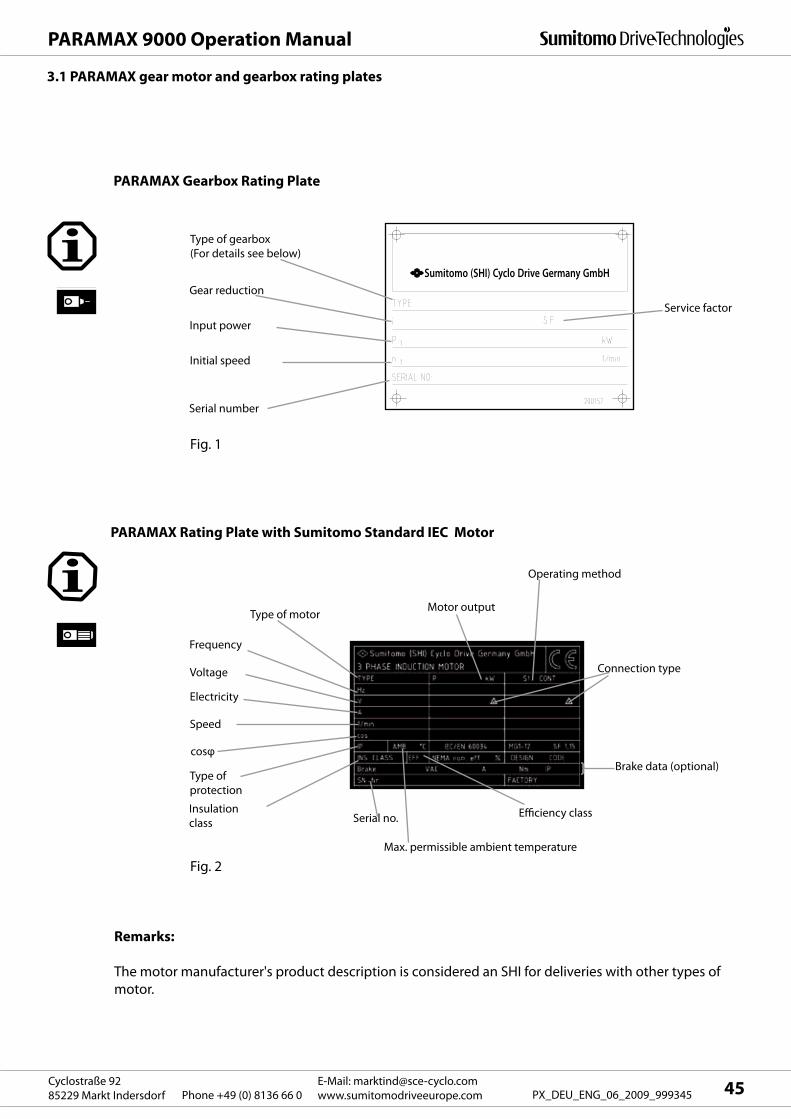
Sumitomo (SHI) Cyclo Drive Germany GmbH
45E-Mail: [email protected]
www.sumitomodriveeurope.comPhone +49 (0) 8136 66 0Cyclostraße 92
85229 Markt Indersdorf PX_DEU_ENG_06_2009_999345
PARAMAX 9000 Operation Manual
3.1 PARAMAX gear motor and gearbox rating plates
PARAMAX Rating Plate with Sumitomo Standard IEC Motor
PARAMAX Gearbox Rating Plate
Fig. 2
Remarks:
The motor manufacturer's product description is considered an SHI for deliveries with other types of
motor.
Type of gearbox
(For details see below)
Gear reduction
Input power
Initial speed
Serial number
Fig. 1
Service factor
Type of motor
Frequency
Voltage
Motor output
Speed
cosφ
Brake data (optional)
Serial no.
Connection type
Operating method
Electricity
Type of
protection
Max. permissible ambient temperature
Insulation
classEfficiency class
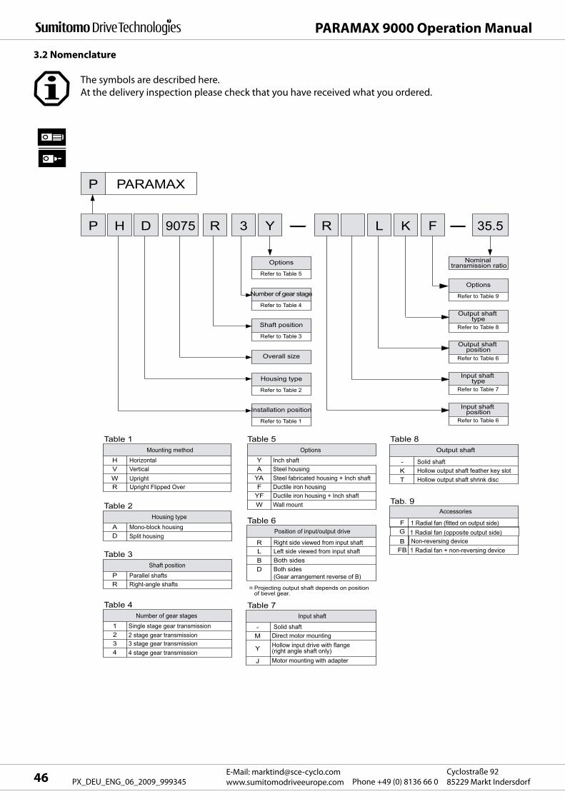
P P
P PARAMAX
H 9075D R 3 Y
Refer to Table 5
Number of gear stage
Refer to Table 4
Shaft position
Refer to Table 3
Overall size
Housing type
Refer to Table 2
Installation position
Refer to Table 1
Options
Options
Refer to Table 9
Nominal transmission ratio
Output shaft type
Refer to Table 8
Output shaft position
Refer to Table 6
Input shaft type
Refer to Table 7
Input shaft position
Refer to Table 6
R L K F 35.5
Mounting methodH HorizontalV Vertical
R Upright Flipped OverW Upright
Table 1 Table 5 Table 8
Tab. 9
Table 6
Table 7
OptionsY Inch shaftA Steel housing
YA
-KT
FGB
FB
Steel fabricated housing + Inch shaft
Solid shaftHollow output shaft feather key slotHollow output shaft shrink disc
F
RLBD
-M
J
Y
Ductile iron housingYF Ductile iron housing + Inch shaftW Wall mount
Housing typeA Mono-block housingD Split housing
Table 2
Shaft positionP Parallel shaftsR Right-angle shafts
Table 3
Number of gear stages1 Single stage gear transmission2 2 stage gear transmission 3 3 stage gear transmission4 4 stage gear transmission
Table 4
Non-reversing device
1 Radial fan (fitted on output side)1 Radial fan (opposite output side)
Direct motor mounting
Motor mounting with adapter
Hollow input drive with flange (right angle shaft only)
1 Radial fan + non-reversing device
Position of input/output drive
Input shaft
Right side viewed from input shaftLeft side viewed from input shaftBoth sides
Solid shaft
Both sides(Gear arrangement reverse of B)
Projecting output shaft depends on position of bevel gear.
Output shaft
Accessories
PARAMAX 9000 Operation Manual
E-Mail: [email protected]
www.sumitomodriveeurope.com Phone +49 (0) 8136 66 0Cyclostraße 92
85229 Markt Indersdorf46 PX_DEU_ENG_06_2009_999345
The symbols are described here.
At the delivery inspection please check that you have received what you ordered.
3.2 Nomenclature
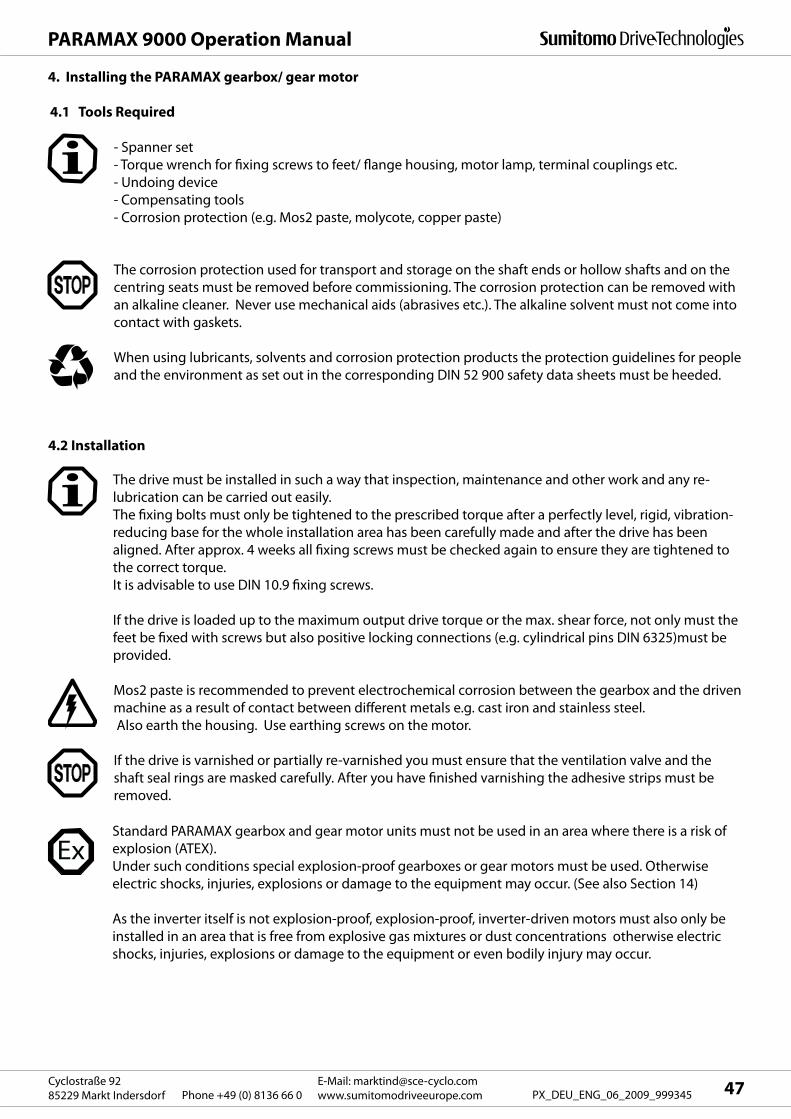
47E-Mail: [email protected]
www.sumitomodriveeurope.comPhone +49 (0) 8136 66 0Cyclostraße 92
85229 Markt Indersdorf PX_DEU_ENG_06_2009_999345
PARAMAX 9000 Operation Manual
4.1 Tools Required
- Spanner set
- Torque wrench for fixing screws to feet/ flange housing, motor lamp, terminal couplings etc.
- Undoing device
- Compensating tools
- Corrosion protection (e.g. Mos2 paste, molycote, copper paste)
The corrosion protection used for transport and storage on the shaft ends or hollow shafts and on the
centring seats must be removed before commissioning. The corrosion protection can be removed with
an alkaline cleaner. Never use mechanical aids (abrasives etc.). The alkaline solvent must not come into
contact with gaskets.
When using lubricants, solvents and corrosion protection products the protection guidelines for people
and the environment as set out in the corresponding DIN 52 900 safety data sheets must be heeded.
4.2 Installation
The drive must be installed in such a way that inspection, maintenance and other work and any re-
lubrication can be carried out easily.
The fixing bolts must only be tightened to the prescribed torque after a perfectly level, rigid, vibration-
reducing base for the whole installation area has been carefully made and after the drive has been
aligned. After approx. 4 weeks all fixing screws must be checked again to ensure they are tightened to
the correct torque.
It is advisable to use DIN 10.9 fixing screws.
If the drive is loaded up to the maximum output drive torque or the max. shear force, not only must the
feet be fixed with screws but also positive locking connections (e.g. cylindrical pins DIN 6325)must be
provided.
Mos2 paste is recommended to prevent electrochemical corrosion between the gearbox and the driven
machine as a result of contact between different metals e.g. cast iron and stainless steel.
Also earth the housing. Use earthing screws on the motor.
If the drive is varnished or partially re-varnished you must ensure that the ventilation valve and the
shaft seal rings are masked carefully. After you have finished varnishing the adhesive strips must be
removed.
4. Installing the PARAMAX gearbox/ gear motor
Standard PARAMAX gearbox and gear motor units must not be used in an area where there is a risk of
explosion (ATEX).
Under such conditions special explosion-proof gearboxes or gear motors must be used. Otherwise
electric shocks, injuries, explosions or damage to the equipment may occur. (See also Section 14)
As the inverter itself is not explosion-proof, explosion-proof, inverter-driven motors must also only be
installed in an area that is free from explosive gas mixtures or dust concentrations otherwise electric
shocks, injuries, explosions or damage to the equipment or even bodily injury may occur.
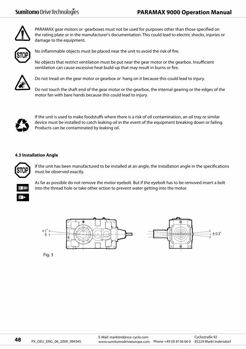
10 0.3
PARAMAX 9000 Operation Manual
E-Mail: [email protected]
www.sumitomodriveeurope.com Phone +49 (0) 8136 66 0Cyclostraße 92
85229 Markt Indersdorf48 PX_DEU_ENG_06_2009_999345
Fig. 3
PARAMAX gear motors or gearboxes must not be used for purposes other than those specified on
the rating plate or in the manufacturer's documentation. This could lead to electric shocks, injuries or
damage to the equipment.
No inflammable objects must be placed near the unit to avoid the risk of fire.
No objects that restrict ventilation must be put near the gear motor or the gearbox. Insufficient
ventilation can cause excessive heat build-up that may result in burns or fire.
Do not tread on the gear motor or gearbox or hang on it because this could lead to injury.
Do not touch the shaft end of the gear motor or the gearbox, the internal gearing or the edges of the
motor fan with bare hands because this could lead to injury.
If the unit is used to make foodstuffs where there is a risk of oil contamination, an oil tray or similar
device must be installed to catch leaking oil in the event of the equipment breaking down or failing.
Products can be contaminated by leaking oil.
4.3 Installation Angle
If the unit has been manufactured to be installed at an angle, the installation angle in the specifications
must be observed exactly.
As far as possible do not remove the motor eyebolt. But if the eyebolt has to be removed insert a bolt
into the thread hole or take other action to prevent water getting into the motor.
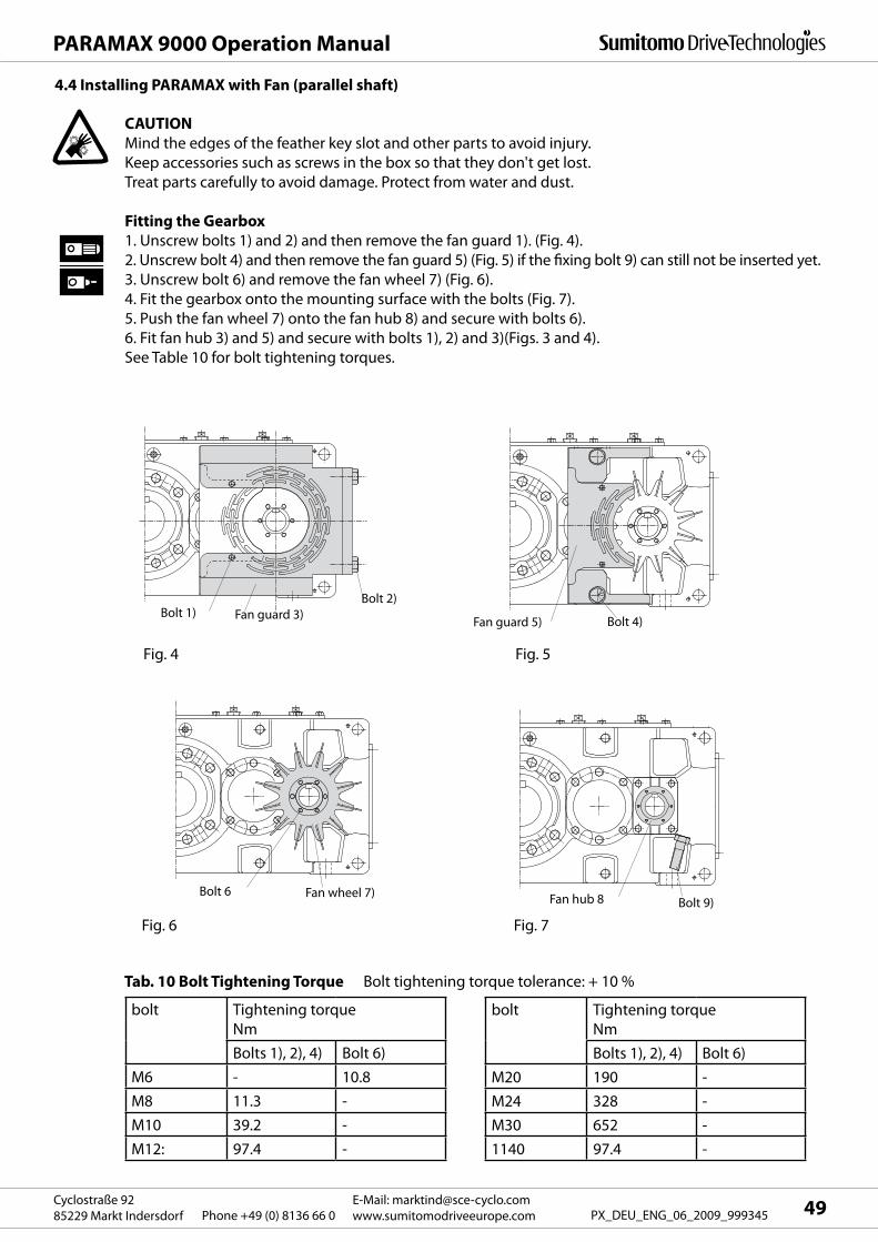
49E-Mail: [email protected]
www.sumitomodriveeurope.comPhone +49 (0) 8136 66 0Cyclostraße 92
85229 Markt Indersdorf PX_DEU_ENG_06_2009_999345
PARAMAX 9000 Operation Manual
Fan guard 3)Bolt 1)Bolt 2)
Fan guard 5) Bolt 4)
Bolt 6 Fan wheel 7)Fan hub 8 Bolt 9)
4.4 Installing PARAMAX with Fan (parallel shaft)
CAUTION
Mind the edges of the feather key slot and other parts to avoid injury.
Keep accessories such as screws in the box so that they don't get lost.
Treat parts carefully to avoid damage. Protect from water and dust.
Fitting the Gearbox
1. Unscrew bolts 1) and 2) and then remove the fan guard 1). (Fig. 4).
2. Unscrew bolt 4) and then remove the fan guard 5) (Fig. 5) if the fixing bolt 9) can still not be inserted yet.
3. Unscrew bolt 6) and remove the fan wheel 7) (Fig. 6).
4. Fit the gearbox onto the mounting surface with the bolts (Fig. 7).
5. Push the fan wheel 7) onto the fan hub 8) and secure with bolts 6).
6. Fit fan hub 3) and 5) and secure with bolts 1), 2) and 3)(Figs. 3 and 4).
See Table 10 for bolt tightening torques.
Fig. 4 Fig. 5
Fig. 6 Fig. 7
Tab. 10 Bolt Tightening Torque Bolt tightening torque tolerance: + 10 %
bolt Tightening torque
Nm
Bolts 1), 2), 4) Bolt 6)
M6 - 10.8
M8 11.3 -
M10 39.2 -
M12: 97.4 -
bolt Tightening torque
Nm
Bolts 1), 2), 4) Bolt 6)
M20 190 -
M24 328 -
M30 652 -
1140 97.4 -
PARAMAX 9000 Operation Manual
E-Mail: [email protected]
www.sumitomodriveeurope.com Phone +49 (0) 8136 66 0Cyclostraße 92
85229 Markt Indersdorf50 PX_DEU_ENG_06_2009_999345
5. Operational area
6. Connecting to other Machines
Cover the rotating parts with suitable devices otherwise there is the risk of injury.
If the PARAMAX DRIVE is connected to a load you must ensure that the alignment deviation
corresponds to the values specified in the maintenance instructions, the drawings, the catalogue etc.
otherwise the system could be damaged because of the deviation.
Tighten the corresponding screws to the torque specified in the drawings and catalogues etc.
otherwise the system may be damaged by loose parts.
If a belt is used to connect the unit to another machine, you must ensure that the belt tension and the
belt pulley parallelity deviation are within the prescribed tolerances. If the unit is connected directly to
another machine you must ensure that the prescribed accuracy deviation limits for this connection are
adhered to otherwise the system may be damaged by any deviations.
If the PARAMAX DRIVE output shaft is to be moved with free rotation (i.e. without load), the feather key
must be removed first otherwise there is the risk of injury.
Check the direction of rotation before you connect the PARAMAX DRIVE to another drive unit. An
unexpected direction of rotation may lead to injury and damage to the system.
Ambient Air Humidity: 85% max.
Height: 1000 m max.
Ambient Air: Free from corrosive and explosive gases and vapours. (Can be used in ATEX after
consultation with the factory). (See Section 14)
The surroundings should be dust-free and well ventilated.
Installation location: Inside, as dust-free as possible with no splash water.
Special configurations are required for installation under conditions other than those mentioned above.
Ambient Temperature: -10° to +40°
Operating at ambient temperatures below -10 °C and above +40 °C must be agreed with the
manufacturer.
When using oil heating (ambient temperature –10 °C) a voltage must be applied to this
permanently.
An integral thermostat will control the oil heating if necessary.
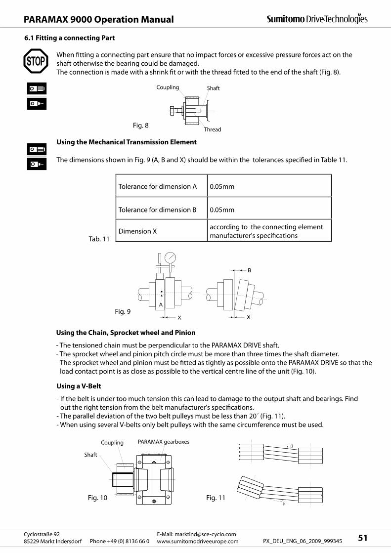
A
X X
B
51E-Mail: [email protected]
www.sumitomodriveeurope.comPhone +49 (0) 8136 66 0Cyclostraße 92
85229 Markt Indersdorf PX_DEU_ENG_06_2009_999345
PARAMAX 9000 Operation Manual
Shaft
Coupling PARAMAX gearboxes
Thread
ShaftCoupling
Fig. 8
6.1 Fitting a connecting Part
When fitting a connecting part ensure that no impact forces or excessive pressure forces act on the
shaft otherwise the bearing could be damaged.
The connection is made with a shrink fit or with the thread fitted to the end of the shaft (Fig. 8).
The dimensions shown in Fig. 9 (A, B and X) should be within the tolerances specified in Table 11.
Tolerance for dimension A 0.05mm
Tolerance for dimension B 0.05mm
Dimension Xaccording to the connecting element
manufacturer's specificationsTab. 11
Fig. 9
Using the Chain, Sprocket wheel and Pinion
- The tensioned chain must be perpendicular to the PARAMAX DRIVE shaft.
- The sprocket wheel and pinion pitch circle must be more than three times the shaft diameter.
- The sprocket wheel and pinion must be fitted as tightly as possible onto the PARAMAX DRIVE so that the
load contact point is as close as possible to the vertical centre line of the unit (Fig. 10).
Fig. 10 Fig. 11
Using the Mechanical Transmission Element
Using a V-Belt
- If the belt is under too much tension this can lead to damage to the output shaft and bearings. Find
out the right tension from the belt manufacturer's specifications.
- The parallel deviation of the two belt pulleys must be less than 20´ (Fig. 11).
- When using several V-belts only belt pulleys with the same circumference must be used.
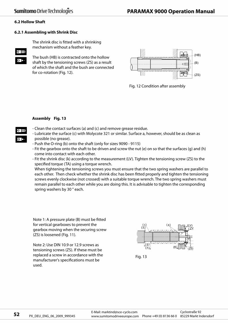
(B)
(HB)
(ZS)
( a)
((
( c)( b )
((ZS)(K)
(LV)( ZY
( g)( h)
PARAMAX 9000 Operation Manual
E-Mail: [email protected]
www.sumitomodriveeurope.com Phone +49 (0) 8136 66 0Cyclostraße 92
85229 Markt Indersdorf52 PX_DEU_ENG_06_2009_999345
6.2 Hollow Shaft
The shrink disc is fitted with a shrinking
mechanism without a feather key.
The bush (HB) is contracted onto the hollow
shaft by the tensioning screws (ZS) as a result
of which the shaft and the bush are connected
for co-rotation (Fig. 12).
Fig. 12 Condition after assembly
Assembly Fig. 13
- Clean the contact surfaces (a) and (c) and remove grease residue.
- Lubricate the surface (c) with Molycote 321 or similar. Surface a, however, should be as clean as
possible (no grease).
- Push the O-ring (b) onto the shaft (only for sizes 9090 - 9115)
- Fit the gearbox onto the shaft to be driven and screw the nut (e) on so that the surfaces (g) and (h)
come into contact with each other.
- Fit the shrink disc (k) according to the measurement (LV). Tighten the tensioning screw (ZS) to the
specified torque (TA) using a torque wrench.
When tightening the tensioning screws you must ensure that the two spring washers are parallel to
each other. Then check whether the shrink disc has been fitted properly and tighten the tensioning
screws evenly clockwise (not crossed) with a suitable torque wrench. The two spring washers must
remain parallel to each other while you are doing this. It is advisable to tighten the corresponding
spring washers by 30 ° each.
Note 1: A pressure plate (B) must be fitted
for vertical gearboxes to prevent the
gearbox moving when the securing screw
(ZS) is loosened (Fig. 11).
Note 2: Use DIN 10.9 or 12.9 screws as
tensioning screws (ZS). If these must be
replaced a screw in accordance with the
manufacturer's specifications must be
used.
Fig. 13
6.2.1 Assembling with Shrink Disc
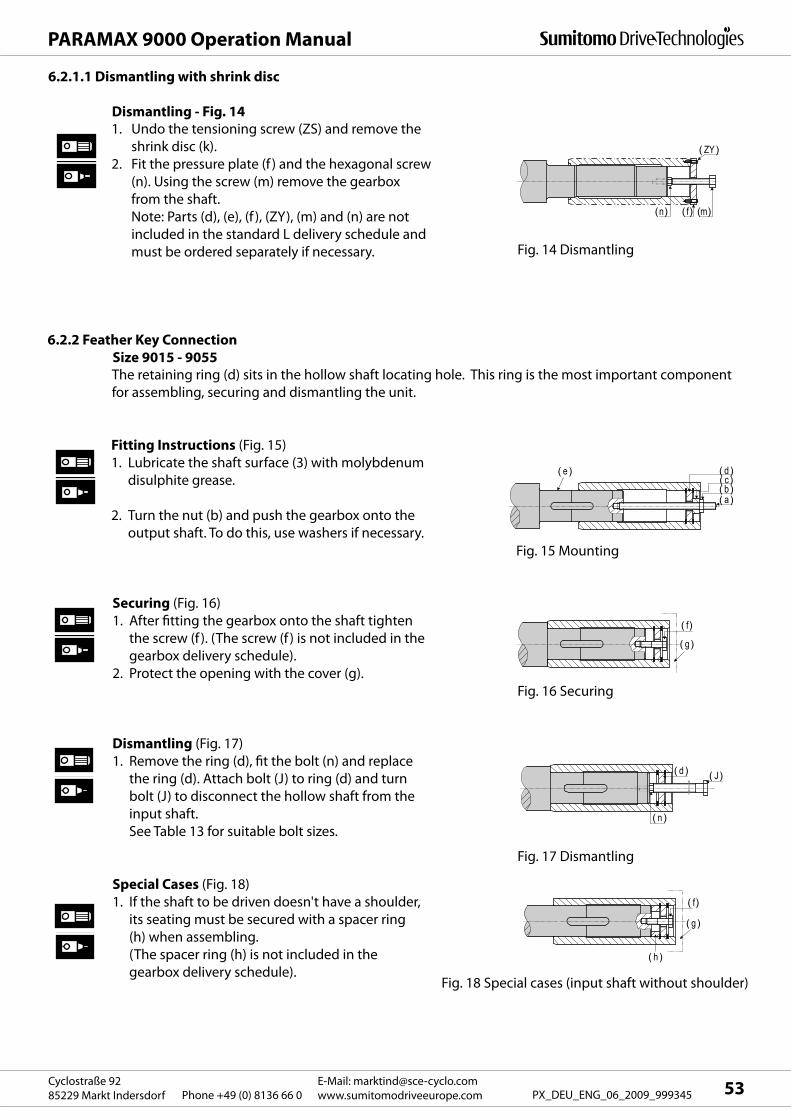
(n) ( f) (m)
( ZY)
( a)
( e ) ( d )( c)( b )
( f)
( g)
( f)
( h )
( g )
( d )
( n )
( J)
53E-Mail: [email protected]
www.sumitomodriveeurope.comPhone +49 (0) 8136 66 0Cyclostraße 92
85229 Markt Indersdorf PX_DEU_ENG_06_2009_999345
PARAMAX 9000 Operation Manual
Dismantling - Fig. 141. Undo the tensioning screw (ZS) and remove the
shrink disc (k).
2. Fit the pressure plate (f ) and the hexagonal screw
(n). Using the screw (m) remove the gearbox
from the shaft.
Note: Parts (d), (e), (f ), (ZY), (m) and (n) are not
included in the standard L delivery schedule and
must be ordered separately if necessary. Fig. 14 Dismantling
6.2.2 Feather Key Connection
Size 9015 - 9055The retaining ring (d) sits in the hollow shaft locating hole. This ring is the most important component
for assembling, securing and dismantling the unit.
Fitting Instructions (Fig. 15)
1. Lubricate the shaft surface (3) with molybdenum
disulphite grease.
2. Turn the nut (b) and push the gearbox onto the
output shaft. To do this, use washers if necessary.
Securing (Fig. 16)
1. After fitting the gearbox onto the shaft tighten
the screw (f ). (The screw (f ) is not included in the
gearbox delivery schedule).
2. Protect the opening with the cover (g).
Dismantling (Fig. 17)
1. Remove the ring (d), fit the bolt (n) and replace
the ring (d). Attach bolt (J) to ring (d) and turn
bolt (J) to disconnect the hollow shaft from the
input shaft.
See Table 13 for suitable bolt sizes.
Special Cases (Fig. 18)
1. If the shaft to be driven doesn't have a shoulder,
its seating must be secured with a spacer ring
(h) when assembling.
(The spacer ring (h) is not included in the
gearbox delivery schedule).
Fig. 15 Mounting
Fig. 16 Securing
Fig. 17 Dismantling
Fig. 18 Special cases (input shaft without shoulder)
6.2.1.1 Dismantling with shrink disc
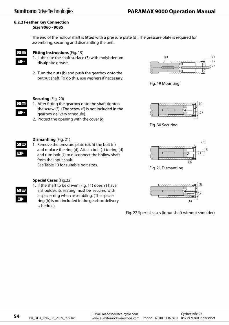
( a )
( e ) d( b)( )
( f)
( g )
( n )
( J )
Fi 2
d( )
( f)
( g )
( h)
PARAMAX 9000 Operation Manual
E-Mail: [email protected]
www.sumitomodriveeurope.com Phone +49 (0) 8136 66 0Cyclostraße 92
85229 Markt Indersdorf54 PX_DEU_ENG_06_2009_999345
6.2.2 Feather Key Connection
Size 9060 - 9085
The end of the hollow shaft is fitted with a pressure plate (d). The pressure plate is required for
assembling, securing and dismantling the unit.
Dismantling (Fig. 21)
1. Remove the pressure plate (d), fit the bolt (n)
and replace the ring (d). Attach bolt (J) to ring (d)
and turn bolt (J) to disconnect the hollow shaft
from the input shaft.
See Table 13 for suitable bolt sizes.
Special Cases (Fig.22)
1. If the shaft to be driven (Fig. 11) doesn't have
a shoulder, its seating must be secured with
a spacer ring when assembling. (The spacer
ring (h) is not included in the gearbox delivery
schedule).
Fig. 19 Mounting
Fig. 30 Securing
Fig. 21 Dismantling
Fig. 22 Special cases (input shaft without shoulder)
Fitting Instructions (Fig. 19)
1. Lubricate the shaft surface (3) with molybdenum
disulphite grease.
2. Turn the nuts (b) and push the gearbox onto the
output shaft. To do this, use washers if necessary.
Securing (Fig. 20)
1. After fitting the gearbox onto the shaft tighten
the screw (f ). (The screw (f ) is not included in the
gearbox delivery schedule).
2. Protect the opening with the cover (g.
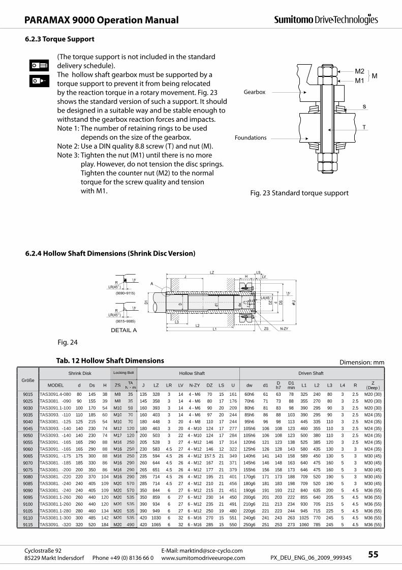
M2M
M1
s
tT
LV
ZS N-ZY
L4(45 )
DZ d DS U1.6
J
D d1 dw z
LZH
LS
L3L2
DETAIL A L1
D1
LR(45 )R
(9015~9085)
1.6
LR(45 )R
(9090~9115)
1.6
A
MODEL d Ds H ZS TAN m J LZ LR LV N-ZY DZ LS U dw d1 D
h7D1min L1 L2 L3 L4 R Z
( )9015 TAS3091.4-080 80 145 38 M8 35 135 328 3 14 4 - M6 70 15 161 60h6 61 63 78 325 240 80 3 2.5 M20 (30)9025 TAS3081. -090 90 155 39 M8 35 145 358 3 14 4 - M6 80 17 176 70h6 71 73 88 355 270 80 3 2.5 M20 (30)9030 TAS3091.1-100 100 170 54 M10 59 160 393 3 14 4 - M6 90 20 209 80h6 81 83 98 390 295 90 3 2.5 M20 (30)9035 TAS3093. -110 110 185 60 M10 70 160 403 3 14 4 - M6 97 20 244 85h6 86 88 103 390 295 90 3 2.5 M24 (35)9040 TAS3081. -125 125 215 54 M10 70 180 448 3 20 4 - M8 110 17 244 95h6 96 98 113 445 335 110 3 2.5 M24 (35)9045 TAS3093. -140 140 230 74 M12 120 180 463 3 20 4 - M10 124 17 277 105h6 106 108 123 460 355 110 3 2.5 M24 (35)9050 TAS3093. -140 140 230 74 M12 120 200 503 3 22 4 - M10 124 17 284 105h6 106 108 123 500 380 110 3 2.5 M24 (35)9055 TAS3091. -165 165 290 88 M16 250 205 528 3 27 4 - M12 146 17 314 120h6 121 123 138 525 385 120 3 2.5 M24 (35)9060 TAS3091. -165 165 290 88 M16 250 230 583 4.5 27 4 - M12 146 12 322 125h6 126 128 143 580 435 130 3 3 M24 (35)9065 TAS3091. -175 175 300 88 M16 250 235 594 4.5 26 4 - M12 157.5 21 349 140h6 141 143 158 589 450 130 5 3 M30 (45)9070 TAS3081. -185 185 330 86 M16 290 260 644 4.5 26 4 - M12 167 21 371 145h6 146 148 163 640 475 160 5 3 M30 (45)9075 TAS3081. -200 200 350 86 M16 290 265 651 4.5 26 4 - M12 177 21 379 155h6 156 158 173 646 475 160 5 3 M30 (45)9080 TAS3081. -220 220 370 104 M16 290 285 714 4.5 26 4 - M12 195 21 401 170g6 171 173 188 709 520 190 5 3 M30 (45)9085 TAS3081. -240 240 405 109 M20 570 285 714 4.5 27 4 - M12 210 21 456 180g6 181 183 198 709 520 190 5 3 M30 (45)9090 TAS3081. -240 240 405 109 M20 570 350 844 6 27 6 - M12 215 21 451 190g6 191 193 212 840 635 200 5 4.5 M36 (55)9095 TAS3081.1-260 260 440 120 M20 535 350 859 6 27 6 - M12 230 14 450 200g6 201 203 222 855 640 205 5 4.5 M36 (55)9100 TAS3081.1-260 260 440 120 M20 535 390 934 6 27 6 - M12 235 21 491 210g6 211 213 234 930 705 215 5 4.5 M36 (55)9105 TAS3081.1-280 280 460 134 M20 535 390 949 6 27 6 - M12 250 19 480 220g6 221 223 244 945 715 225 5 4.5 M36 (55)9110 TAS3081.1-300 300 485 142 M20 535 420 1030 6 32 6 - M16 270 15 551 240g6 241 243 263 1025 770 245 5 4.5 M36 (55)9115 TAS3091. -320 320 520 184 M20 490 420 1065 6 32 6 - M16 285 15 550 250g6 251 253 273 1060 785 245 5 4.5 M36 (55)
GrößeShrink Disk Hollow Shaft Driven Shaft
Dimension: mm
Locking Bolt
ZS TATTN m
M8 35M8 35
M10 59M10 70M10 70M12 120M12 120M16 250M16 250M16 250M16 290M16 290M16 290M20 570M20 570M20 535M20 535M20 535M20 535M20 490
Locking Bolt
Deep
55E-Mail: [email protected]
www.sumitomodriveeurope.comPhone +49 (0) 8136 66 0Cyclostraße 92
85229 Markt Indersdorf PX_DEU_ENG_06_2009_999345
PARAMAX 9000 Operation Manual
Tab. 12 Hollow Shaft Dimensions
Fig. 24
(The torque support is not included in the standard
delivery schedule).
The hollow shaft gearbox must be supported by a
torque support to prevent it from being relocated
by the reaction torque in a rotary movement. Fig. 23
shows the standard version of such a support. It should
be designed in a suitable way and be stable enough to
withstand the gearbox reaction forces and impacts.
Note 1: The number of retaining rings to be used
depends on the size of the gearbox.
Note 2: Use a DIN quality 8.8 screw (T) and nut (M).
Note 3: Tighten the nut (M1) until there is no more
play. However, do not tension the disc springs.
Tighten the counter nut (M2) to the normal
torque for the screw quality and tension
with M1. Fig. 23 Standard torque support
6.2.4 Hollow Shaft Dimensions (Shrink Disc Version)
6.2.3 Torque Support
Gearbox
Foundations
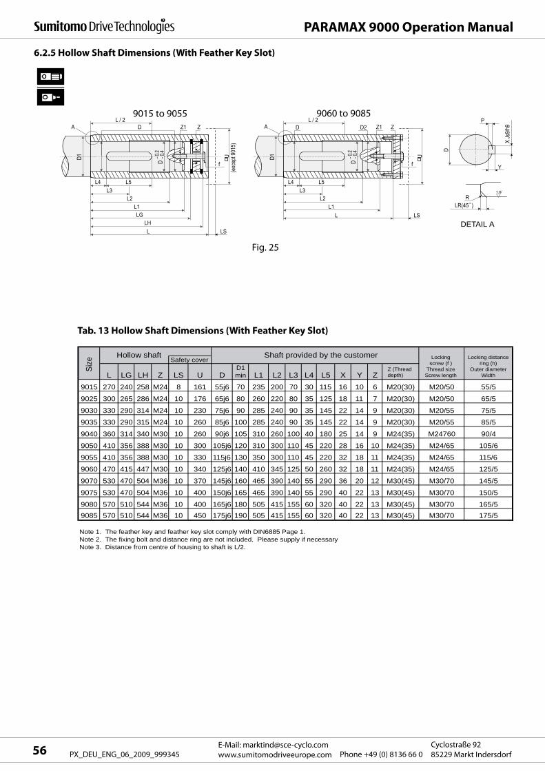
Y
P
X Js
9/h9
D
LR(45 )R
1.6
LSL
LSL
Z1D
f
L4 L5L3
L2L1
D- 0
.2- 0
.4
U
L / 2
D1
D2 ZAZ1D Z
f
L4 L5L3
L2L1LG
LH
D- 0
.2- 0
.4
U(e
xcep
t 901
5)
L / 2
D1
A
DETAIL A
L LG LH Z LS U DD1min L1 L2 L3 L4 L5 X Y Z
Z (Thread depth)
9015 270 240 258 M24 8 161 55j6 70 235 200 70 30 115 16 10 6 M20(30) M20/50 55/5
9025 300 265 286 M24 10 176 65j6 80 260 220 80 35 125 18 11 7 M20(30) M20/50 65/5
9030 330 290 314 M24 10 230 75j6 90 285 240 90 35 145 22 14 9 M20(30) M20/55 75/5
9035 330 290 315 M24 10 260 85j6 100 285 240 90 35 145 22 14 9 M20(30) M20/55 85/5
9040 360 314 340 M30 10 260 90j6 105 310 260 100 40 180 25 14 9 M24(35) M24760 90/4
9050 410 356 388 M30 10 300 105j6 120 310 300 110 45 220 28 16 10 M24(35) M24/65 105/6
9055 410 356 388 M30 10 330 115j6 130 350 300 110 45 220 32 18 11 M24(35) M24/65 115/6
9060 470 415 447 M30 10 340 125j6 140 410 345 125 50 260 32 18 11 M24(35) M24/65 125/5
9070 530 470 504 M36 10 370 145j6 160 465 390 140 55 290 36 20 12 M30(45) M30/70 145/5
9075 530 470 504 M36 10 400 150j6 165 465 390 140 55 290 40 22 13 M30(45) M30/70 150/5
9080 570 510 544 M36 10 400 165j6 180 505 415 155 60 320 40 22 13 M30(45) M30/70 165/59085 570 510 544 M36 10 450 175j6 190 505 415 155 60 320 40 22 13 M30(45) M30/70 175/5
Note 1. The feather key and feather key slot comply with DIN6885 Page 1.Note 2. The fixing bolt and distance ring are not included. Please supply if necessaryNote 3. Distance from centre of housing to shaft is L/2.
Locking distancering (h)
Outer diameterWidth
Size Safety cover
Hollow shaft Shaft provided by the customer Lockingscrew (f )
Thread sizeScrew length
PARAMAX 9000 Operation Manual
E-Mail: [email protected]
www.sumitomodriveeurope.com Phone +49 (0) 8136 66 0Cyclostraße 92
85229 Markt Indersdorf56 PX_DEU_ENG_06_2009_999345
6.2.5 Hollow Shaft Dimensions (With Feather Key Slot)
9015 to 9055 9060 to 9085
Fig. 25
Tab. 13 Hollow Shaft Dimensions (With Feather Key Slot)
57E-Mail: [email protected]
www.sumitomodriveeurope.comPhone +49 (0) 8136 66 0Cyclostraße 92
85229 Markt Indersdorf PX_DEU_ENG_06_2009_999345
PARAMAX 9000 Operation Manual
7. Electrical Installation
Installation, connection and commissioning work as well as maintenance and repairs must only be
carried out by qualified experts.
Before any work starts on the motor or the gear motor but particularly before covers are taken off active
parts the motor must be disconnected as prescribed.
The 5 safety rules as set out in DIN VDE 0105 must be obeyed.
These electric motors comply with the standards and regulations in force and meet the requirements of
the Low Voltage Directive 73/23/EWG.
The electrical connection of a standard Sumitomo 3 phase motor is described below.
Information on brake motors, servo motors, direct current motors and motors made by other
manufacturers can be found if applicable in the relevant operating instructions.
Do not carry out any work on the unit if it is live. Be sure to turn off the power to prevent electric shocks.
Connect the unit to the mains cable according to the circuit diagram on the terminal block or the
operating instructions otherwise there is the risk of electric shocks or fire.
Do not bend, pull or grasp the mains cable excessively otherwise there is the risk of electric shocks or
fire.
Earth the earthing bolt otherwise there is the risk of electric shocks or fire.When the motor and other electrical components are connected to the electricity the electrical codes
and connection conditions provided by the factory must be obeyed otherwise there is the risk of burns,
electric shocks, injuries and fire. The motor is not fitted with any protective device. However, overload
protection must be fitted in accordance with the electrical regulations provided by the factory. It is
advisable to install other protective devices (earth leakage breaker, etc.), in addition to an overload
protector, in order to prevent burns, electric shocks, injury and fire.
Never touch the terminals when measuring the insulation resistance to prevent electric shocks.
If a star delta starter is used then only use one with an electromagnetic switch on the primary side
(3 contact type) otherwise there is the risk of fire.
If a 400v inverter is used for the input drive a suppressor filter or reactor must be fitted on the side with
the inverter or the insulation on the motor side must be increased otherwise there is the risk of fire or
damage to the equipment caused by dielectric breakdown.
When using long cables the drop in voltage must be noted. Therefore cables with the appropriate
diameter must be chosen so that this value does not exceed 2%.
7.1 Safety Notes

PARAMAX 9000 Operation Manual
E-Mail: [email protected]
www.sumitomodriveeurope.com Phone +49 (0) 8136 66 0Cyclostraße 92
85229 Markt Indersdorf58 PX_DEU_ENG_06_2009_999345
7.2 Measuring the Insulation Resistance
When measuring the insulation resistance, disconnect the motor from the control panel. Check the
motor separately.
Measure the insulation resistance before connecting. The insulation resistance(R) varies depending
on the motor power, voltage, type of insulation, coil temperature, humidity, contamination, operating
period, test electrification period etc. Normally the insulation resistance should not exceed the values in
Table 14.
Tab. 14 - Insulation resistance
A drop in insulation resistance can normally be attributed to poor insulation. In this case the power
supply must not be switched on. Please contact a representative, a dealer or a local sales office.
1. A circuit fuse must be used to protect against short circuits.
2. The operating current on the motor rating plate must not be exceeded. An appropriate overload
protection device must be used.
7.3 Protection Co-Ordination
Reference: The following equations are shown in JEC - 2100.
R =Rated voltage (V)
Rated output (kW) + 1000
(M Ω)
R =Rated voltage (V) + Speed (rpm)/3
Rated output (kW) + 2000
+ 0.5 (M Ω)
Motor voltage Megohmmeter voltage Insulation resistance (R)
Low voltage motor
600 V or less500 V 1 M W or more
High voltage motor
300 V or more1,000 V 1 M W or more
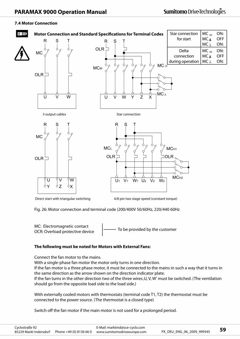
MC
OLR
R
U Y
S
V Z
T
W X
R
U1 V1 W1 U2 W2 V2
S T
MCH1 MCL
MCH2
OLR OLR
MC
OLR
R
U
S
V
T
W
R
U V W Y X Z
S T
MC DMCM
MC
OLR
Y
59E-Mail: [email protected]
www.sumitomodriveeurope.comPhone +49 (0) 8136 66 0Cyclostraße 92
85229 Markt Indersdorf PX_DEU_ENG_06_2009_999345
PARAMAX 9000 Operation Manual
7.4 Motor Connection
3 output cables Star connection
Direct start with triangular switching 4/8 pin two stage speed (constant torque)
Fig. 26: Motor connection and terminal code (200/400V 50/60Hz, 220/440 60Hz
MC: Electromagnetic contact
OCR: Overload protective deviceTo be provided by the customer
The following must be noted for Motors with External Fans:
Connect the fan motor to the mains.
With a single-phase fan motor the motor only turns in one direction.
If the fan motor is a three phase motor, it must be connected to the mains in such a way that it turns in
the same direction as the arrow shown on the direction indicator plate.
If the fan turns in the other direction two of the three wires ‚U, V, W‘ must be switched. (The ventilation
should go from the opposite load side to the load side.)
With externally cooled motors with thermostats (terminal code T1, T2) the thermostat must be
connected to the power source. (The thermostat is a closed type)
Switch off the fan motor if the main motor is not used for a prolonged period.
Motor Connection and Standard Specifications for Terminal Codes Star connection
for start
MC ON:
MC OFF
MC ON:
Delta
connection
during operation
MC ON:
MC OFF
MC ON:
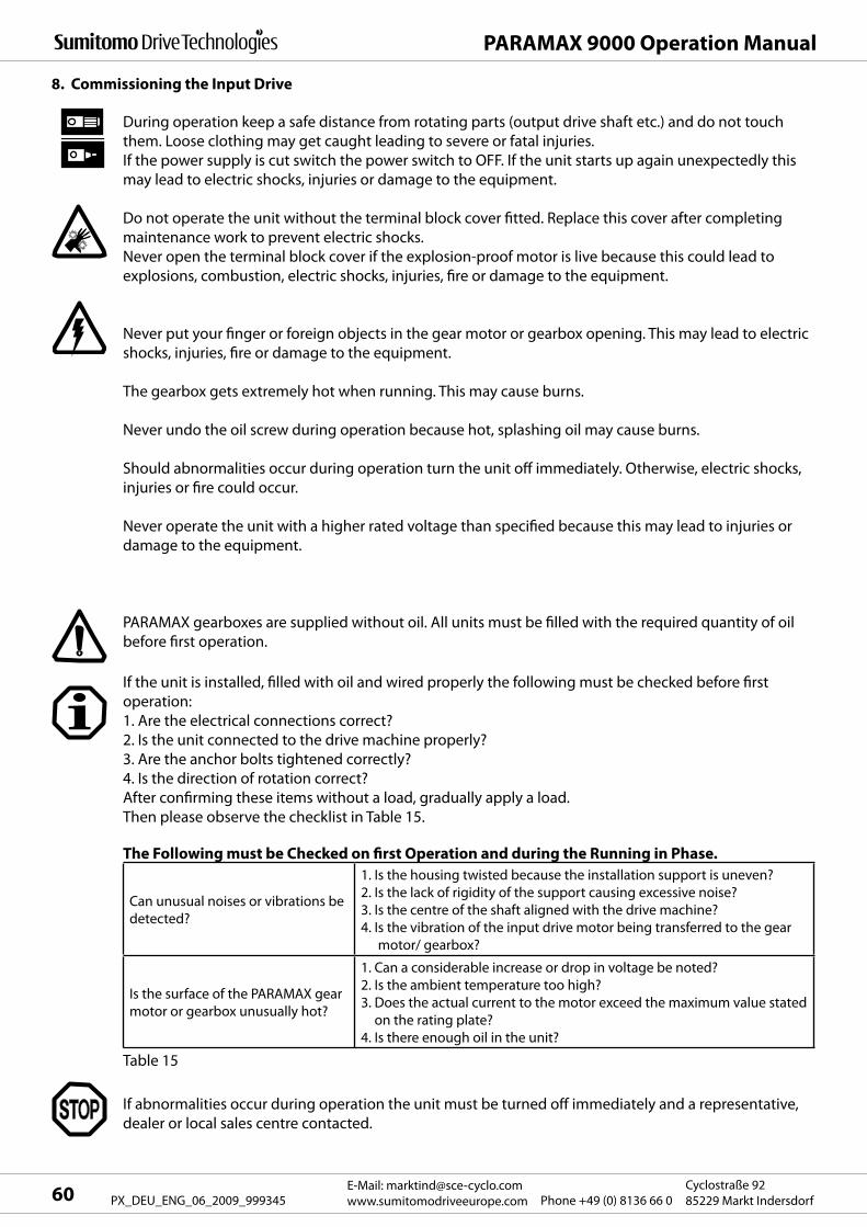
PARAMAX 9000 Operation Manual
E-Mail: [email protected]
www.sumitomodriveeurope.com Phone +49 (0) 8136 66 0Cyclostraße 92
85229 Markt Indersdorf60 PX_DEU_ENG_06_2009_999345
8. Commissioning the Input Drive
During operation keep a safe distance from rotating parts (output drive shaft etc.) and do not touch
them. Loose clothing may get caught leading to severe or fatal injuries.
If the power supply is cut switch the power switch to OFF. If the unit starts up again unexpectedly this
may lead to electric shocks, injuries or damage to the equipment.
Do not operate the unit without the terminal block cover fitted. Replace this cover after completing
maintenance work to prevent electric shocks.
Never open the terminal block cover if the explosion-proof motor is live because this could lead to
explosions, combustion, electric shocks, injuries, fire or damage to the equipment.
Never put your finger or foreign objects in the gear motor or gearbox opening. This may lead to electric
shocks, injuries, fire or damage to the equipment.
The gearbox gets extremely hot when running. This may cause burns.
Never undo the oil screw during operation because hot, splashing oil may cause burns.
Should abnormalities occur during operation turn the unit off immediately. Otherwise, electric shocks,
injuries or fire could occur.
Never operate the unit with a higher rated voltage than specified because this may lead to injuries or
damage to the equipment.
PARAMAX gearboxes are supplied without oil. All units must be filled with the required quantity of oil
before first operation.
If abnormalities occur during operation the unit must be turned off immediately and a representative,
dealer or local sales centre contacted.
Can unusual noises or vibrations be
detected?
1. Is the housing twisted because the installation support is uneven?
2. Is the lack of rigidity of the support causing excessive noise?
3. Is the centre of the shaft aligned with the drive machine?
4. I s the vibration of the input drive motor being transferred to the gear
motor/ gearbox?
Is the surface of the PARAMAX gear
motor or gearbox unusually hot?
1. Can a considerable increase or drop in voltage be noted?
2. Is the ambient temperature too high?
3. Does the actual current to the motor exceed the maximum value stated
on the rating plate?
4. Is there enough oil in the unit?
If the unit is installed, filled with oil and wired properly the following must be checked before first
operation:
1. Are the electrical connections correct?
2. Is the unit connected to the drive machine properly?
3. Are the anchor bolts tightened correctly?
4. Is the direction of rotation correct?
After confirming these items without a load, gradually apply a load.
Then please observe the checklist in Table 15.
The Following must be Checked on first Operation and during the Running in Phase.
Table 15
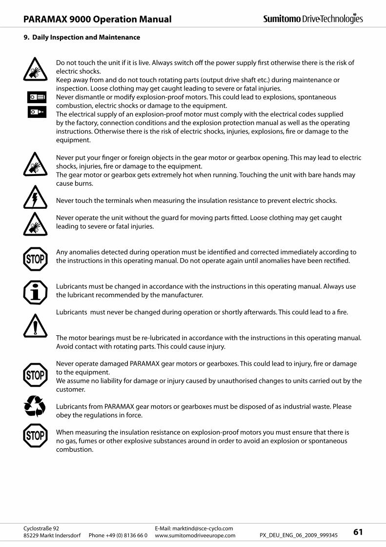
61E-Mail: [email protected]
www.sumitomodriveeurope.comPhone +49 (0) 8136 66 0Cyclostraße 92
85229 Markt Indersdorf PX_DEU_ENG_06_2009_999345
PARAMAX 9000 Operation Manual
9. Daily Inspection and Maintenance
Do not touch the unit if it is live. Always switch off the power supply first otherwise there is the risk of
electric shocks.
Keep away from and do not touch rotating parts (output drive shaft etc.) during maintenance or
inspection. Loose clothing may get caught leading to severe or fatal injuries.
Never dismantle or modify explosion-proof motors. This could lead to explosions, spontaneous
combustion, electric shocks or damage to the equipment.
The electrical supply of an explosion-proof motor must comply with the electrical codes supplied
by the factory, connection conditions and the explosion protection manual as well as the operating
instructions. Otherwise there is the risk of electric shocks, injuries, explosions, fire or damage to the
equipment.
Never put your finger or foreign objects in the gear motor or gearbox opening. This may lead to electric
shocks, injuries, fire or damage to the equipment.
The gear motor or gearbox gets extremely hot when running. Touching the unit with bare hands may
cause burns.
Never touch the terminals when measuring the insulation resistance to prevent electric shocks.
Never operate the unit without the guard for moving parts fitted. Loose clothing may get caught
leading to severe or fatal injuries.
Any anomalies detected during operation must be identified and corrected immediately according to
the instructions in this operating manual. Do not operate again until anomalies have been rectified.
Lubricants must be changed in accordance with the instructions in this operating manual. Always use
the lubricant recommended by the manufacturer.
Lubricants must never be changed during operation or shortly afterwards. This could lead to a fire.
The motor bearings must be re-lubricated in accordance with the instructions in this operating manual.
Avoid contact with rotating parts. This could cause injury.
Never operate damaged PARAMAX gear motors or gearboxes. This could lead to injury, fire or damage
to the equipment.
We assume no liability for damage or injury caused by unauthorised changes to units carried out by the
customer.
Lubricants from PARAMAX gear motors or gearboxes must be disposed of as industrial waste. Please
obey the regulations in force.
When measuring the insulation resistance on explosion-proof motors you must ensure that there is
no gas, fumes or other explosive substances around in order to avoid an explosion or spontaneous
combustion.
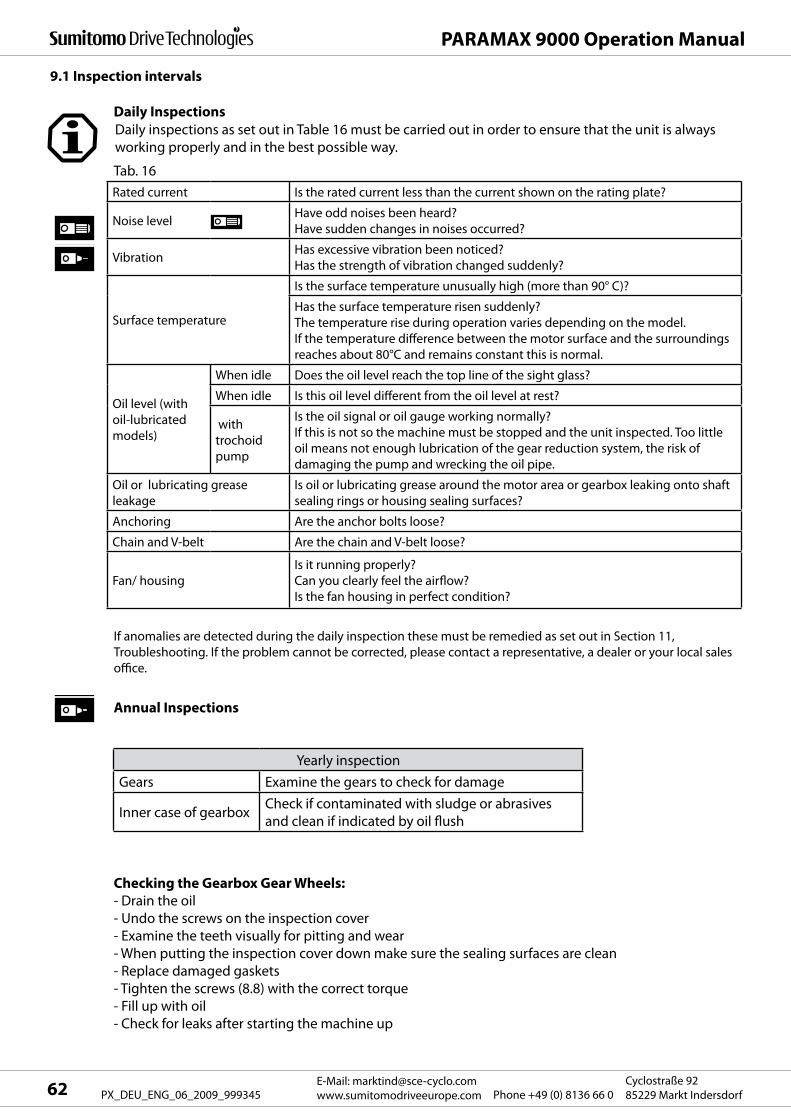
PARAMAX 9000 Operation Manual
E-Mail: [email protected]
www.sumitomodriveeurope.com Phone +49 (0) 8136 66 0Cyclostraße 92
85229 Markt Indersdorf62 PX_DEU_ENG_06_2009_999345
Rated current Is the rated current less than the current shown on the rating plate?
Noise levelHave odd noises been heard?
Have sudden changes in noises occurred?
VibrationHas excessive vibration been noticed?
Has the strength of vibration changed suddenly?
Surface temperature
Is the surface temperature unusually high (more than 90° C)?
Has the surface temperature risen suddenly?
The temperature rise during operation varies depending on the model.
If the temperature difference between the motor surface and the surroundings
reaches about 80°C and remains constant this is normal.
Oil level (with
oil-lubricated
models)
When idle Does the oil level reach the top line of the sight glass?
When idle Is this oil level different from the oil level at rest?
with
trochoid
pump
Is the oil signal or oil gauge working normally?
If this is not so the machine must be stopped and the unit inspected. Too little
oil means not enough lubrication of the gear reduction system, the risk of
damaging the pump and wrecking the oil pipe.
Oil or lubricating grease
leakage
Is oil or lubricating grease around the motor area or gearbox leaking onto shaft
sealing rings or housing sealing surfaces?
Anchoring Are the anchor bolts loose?
Chain and V-belt Are the chain and V-belt loose?
Fan/ housing
Is it running properly?
Can you clearly feel the airflow?
Is the fan housing in perfect condition?
9.1 Inspection intervals
Daily inspections as set out in Table 16 must be carried out in order to ensure that the unit is always
working properly and in the best possible way.
Tab. 16
If anomalies are detected during the daily inspection these must be remedied as set out in Section 11,
Troubleshooting. If the problem cannot be corrected, please contact a representative, a dealer or your local sales
office.
Annual Inspections
Daily Inspections
Checking the Gearbox Gear Wheels:
- Drain the oil
- Undo the screws on the inspection cover
- Examine the teeth visually for pitting and wear
- When putting the inspection cover down make sure the sealing surfaces are clean
- Replace damaged gaskets
- Tighten the screws (8.8) with the correct torque
- Fill up with oil
- Check for leaks after starting the machine up
Yearly inspection
Gears Examine the gears to check for damage
Inner case of gearboxCheck if contaminated with sludge or abrasives
and clean if indicated by oil flush
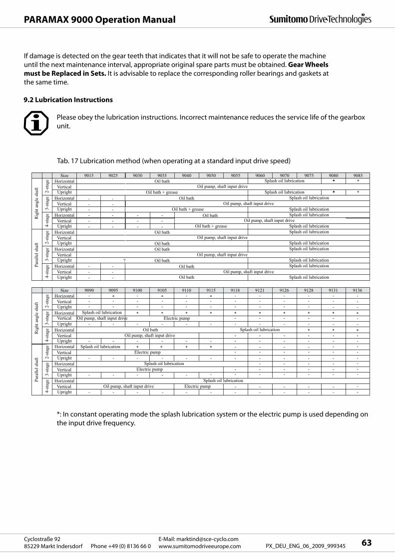
9025Size
2-st
age
3-st
age
Rig
ht a
ngle
shaf
tPa
ralle
l sha
ft
4-st
age
2-st
age
3-st
age
4-st
age
9030 9035 9040 9050 9055 9060 9070 9075 9080 9085Horizontal Oil bath Splash oil lubrication **
Vertical Oil pump, shaft input drive
Oil pump, shaft input drive
Oil pump, shaft input drive
Oil pump, shaft input drive
Upright Oil bath + grease
Oil bath + grease
Splash oil lubrication **
*
*Horizontal Oil bath
Oil bath
Oil bath
Oil bath
Splash oil lubricationVerticalUpright Splash oil lubrication
Horizontal - - Splash oil lubricationVertical - -
9015
Upright - -
----
--
--
--
-- Oil bath + grease Splash oil lubrication
Horizontal Oil bath
Oil bathOil bath
Oil bath
Splash oil lubricationVertical Oil pump, shaft input drive
Oil pump, shaft input drive
Upright Splash oil lubricationHorizontal Splash oil lubrication
VerticalUpright ? Splash oil lubrication
Horizontal Splash oil lubricationVerticalUpright
---
--- Splash oil lubrication
9095Size
2-st
age
3-st
age
Rig
ht a
ngle
shaf
tPa
ralle
l sha
ft
4-st
age
2-st
age
3-st
age
4-st
age
9100 9105 9110 9115 9118 9121 9126 9128 9131 9136Horizontal
Oil bath
Splash oil lubrication
Splash oil lubrication
Splash oil lubrication
Splash oil lubrication
Vertical
Oil pump, shaft input drive
Oil pump, shaft input drive
Oil pump, shaft input drive
Electric pump
Electric pump
Electric pump
Electric pump
Upright-
HorizontalVerticalUpright
HorizontalVertical
9090
Upright
- -
- -
- - - -
- - --
- - -
- - -
-
- - - - - - - -
--
*-
- -
- -
--
*-
- -
- -
--
*-
- -
-- - - -
-
-- -
- -
- -
-- -
*********
* * * *
*
** *
- - - --
-
- -
-- -
-- --
-- -
- -- -- -- -
----- --
-
--
----
-
--
----
-
--
----
-
--- - - -
-
--
-
-
-
-
-
-
-
Horizontal
Splash oil lubrication
VerticalUpright
HorizontalVerticalUpright
HorizontalVerticalUpright
63E-Mail: [email protected]
www.sumitomodriveeurope.comPhone +49 (0) 8136 66 0Cyclostraße 92
85229 Markt Indersdorf PX_DEU_ENG_06_2009_999345
PARAMAX 9000 Operation Manual
If damage is detected on the gear teeth that indicates that it will not be safe to operate the machine
until the next maintenance interval, appropriate original spare parts must be obtained. Gear Wheels
must be Replaced in Sets. It is advisable to replace the corresponding roller bearings and gaskets at
the same time.
9.2 Lubrication Instructions
Please obey the lubrication instructions. Incorrect maintenance reduces the service life of the gearbox
unit.
Tab. 17 Lubrication method (when operating at a standard input drive speed)
*: In constant operating mode the splash lubrication system or the electric pump is used depending on
the input drive frequency.
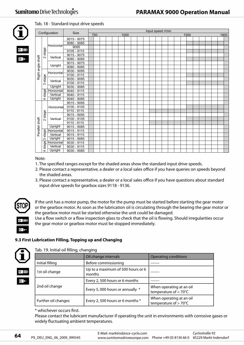
9015 - 90759080 - 9085
90959105 - 91159015 - 90759080 - 90859015 - 90759080 - 90859030 - 90959100 - 91159030 - 90959100 - 9115
Upright
Upright
9030 - 90859040 - 91159040 - 9115
Upright 9040 - 90859015 - 90959100 - 91059110 - 91159015 - 90959100 - 91059110 - 9115
Upright 9015 - 90859015 - 91159015 - 9115
Upright 9015 - 90859030 - 91159030 - 9115
Upright 9030 - 9085
Horizontal
Horizontal
Horizontal
Horizontal
Configuration Size
Horizontal
2 s
tage
3 st
age
2 st
age
Par
alle
l sha
ftR
ight
ang
le s
haft
3 st
age
4 st
age
4 st
age
Vertical
Vertical
Vertical
Vertical
Vertical
Vertical
1000 1500 1800Input speed r/min
Horizontal
750
PARAMAX 9000 Operation Manual
E-Mail: [email protected]
www.sumitomodriveeurope.com Phone +49 (0) 8136 66 0Cyclostraße 92
85229 Markt Indersdorf64 PX_DEU_ENG_06_2009_999345
Tab. 18 - Standard input drive speeds
Note:
1. The specified ranges except for the shaded areas show the standard input drive speeds.
2. Please contact a representative, a dealer or a local sales office if you have queries on speeds beyond
the shaded areas.
3. Please contact a representative, a dealer or a local sales office if you have questions about standard
input drive speeds for gearbox sizes 9118 - 9136.
If the unit has a motor pump, the motor for the pump must be started before starting the gear motor
or the gearbox motor. As soon as the lubrication oil is circulating through the bearing the gear motor or
the gearbox motor must be started otherwise the unit could be damaged.
Use a flow switch or a flow inspection glass to check that the oil is flowing. Should irregularities occur
the gear motor or gearbox motor must be stopped immediately.
9.3 First Lubrication Filling, Topping up and Changing
Tab. 19. Initial oil filling, changing
Oil change intervals Operating conditions
Initial filling Before commissioning -------
1st oil changeUp to a maximum of 500 hours or 6
months-------
2nd oil change
Every 2, 500 hours or 6 months -------
Every 5, 000 hours or annually *When operating at an oil
temperature of < 70°C
Further oil changes Every 2, 500 hours or 6 months *When operating at an oil
temperature of > 70°C
* whichever occurs first.
Please contact the lubricant manufacturer if operating the unit in environments with corrosive gases or
widely fluctuating ambient temperatures.
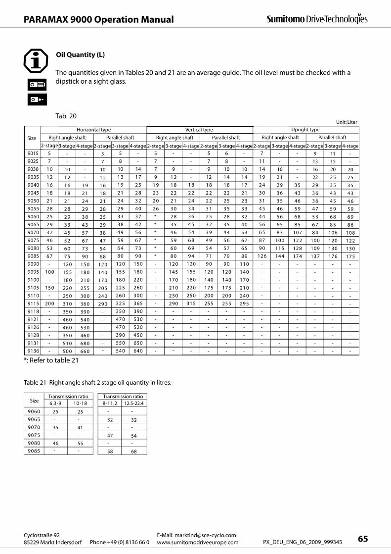
Upright type
Right angle shaft Parallel shaft
7
1 1
1 4
1 9
2 4
3 0
3 1
4 5
4 4
5 6
6 5
8 7
9 0
126
-
-
-
-
-
-
-
-
-
-
-
-
Size
9015
9025
9030
9035
9040
9045
9050
9055
9060
9065
9070
9075
9080
9085
9090
9095
9100
9105
9110
9115
9118
9121
9126
9128
9131
9136
Horizontal type
Right angle shaft Parallel shaft
2-stage
5
7
1 0
1 2
1 6
1 8
2 1
2 8
2 5
2 9
3 7
4 6
5 3
6 7
-
100
-
150
-
200
-
-
-
-
-
-
-
-
16
2 1
2 9
3 6
3 5
4 6
5 6
6 5
8 3
100
115
144
-
-
-
-
-
-
-
-
-
-
-
-
-
-
-
-
3 5
4 3
4 6
5 9
6 8
8 5
107
122
128
174
-
-
-
-
-
-
-
-
-
-
-
-
9
13
16
22
2 9
3 6
3 6
4 7
5 3
6 7
8 4
100
109
137
-
-
-
-
-
-
-
-
-
-
-
-
11
15
20
2 5
3 5
4 3
4 5
5 9
6 8
8 5
106
120
130
176
-
-
-
-
-
-
-
-
-
-
-
-
-
-
20
2 5
3 5
4 3
4 6
5 9
6 9
8 6
108
122
130
175
-
-
-
-
-
-
-
-
-
-
-
-
3-stage
-
-
10
1 2
1 6
1 8
2 1
2 8
2 9
3 3
4 5
5 2
6 0
7 5
120
155
180
220
250
310
350
460
460
350
510
500
4-stage 2-stage 3-stage 4-stage 2-stage 3-stage 4-stage 2-stage 3-stage 4-stage 2-stage 3-stage 4-stage2-stage 3-stage 4-stage
-
-
-
-
1 9
2 1
2 4
2 9
3 8
4 3
5 7
6 7
7 3
9 0
150
180
210
255
300
360
390
540
530
460
680
660
5
7
10
1 2
1 6
1 8
2 1
2 8
2 5
2 9
3 8
4 7
5 4
6 8
120
140
170
205
240
290
-
-
-
-
--
5
8
10
1 3
1 9
2 1
2 4
2 9
3 3
3 8
4 9
5 9
6 4
8 0
120
155
180
225
260
325
350
470
470
390
550
540
-
-
14
1 7
2 5
2 8
3 2
4 0
3 7
4 2
5 6
6 7
7 3
9 0
150
180
220
260
300
365
390
530
520
450
650
640
Vertical type
Right angle shaft Parallel shaft
5
7
7
9
1 9
2 3
2 0
2 6
*
*
*
*
*
*
-
-
-
-
-
-
-
-
-
-
-
-
Unit: Liter
-
-
9
1 2
1 8
2 2
2 1
3 0
2 8
3 5
4 6
5 9
6 0
8 0
120
145
170
210
230
290
-
-
-
-
-
-
-
-
-
-
1 8
2 2
2 4
3 4
3 6
4 5
5 4
6 8
6 9
9 4
120
155
180
220
250
315
-
-
-
-
-
-
5
7
9
12
1 8
2 2
2 2
3 1
2 5
3 2
3 9
4 9
5 4
7 1
9 0
120
140
175
200
255
-
-
-
-
-
-
6
8
10
1 4
1 8
2 2
2 5
3 5
2 8
3 5
4 4
5 6
5 7
7 9
9 0
120
140
175
200
255
-
-
-
-
-
-
-
-
10
1 4
1 7
2 1
2 3
3 3
3 2
4 0
5 3
6 7
6 5
8 9
110
140
170
210
240
295
-
-
-
-
-
-
* : Refer to the Table 33
Table 21 Right angle shaft 2 stage oil quantity in litres.
9060
Size
9065
9070
9075
9080
9085
6.3-9
25 -
35 -
46 -
10-18
25 -
41
-
55 -
8-11.2
-
32 -
47 -
58
12.5-22.4
-
32 -
54 -
68
Transmission ratio Transmission ratio
*: Refer to table 21
65E-Mail: [email protected]
www.sumitomodriveeurope.comPhone +49 (0) 8136 66 0Cyclostraße 92
85229 Markt Indersdorf PX_DEU_ENG_06_2009_999345
PARAMAX 9000 Operation Manual
Oil Quantity (L)
The quantities given in Tables 20 and 21 are an average guide. The oil level must be checked with a
dipstick or a sight glass.
Tab. 20
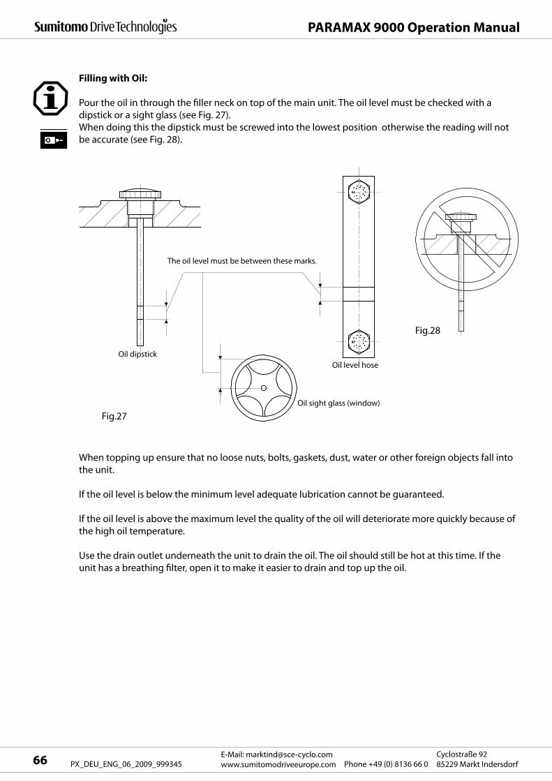
PARAMAX 9000 Operation Manual
E-Mail: [email protected]
www.sumitomodriveeurope.com Phone +49 (0) 8136 66 0Cyclostraße 92
85229 Markt Indersdorf66 PX_DEU_ENG_06_2009_999345
Filling with Oil:
Pour the oil in through the filler neck on top of the main unit. The oil level must be checked with a
dipstick or a sight glass (see Fig. 27).
When doing this the dipstick must be screwed into the lowest position otherwise the reading will not
be accurate (see Fig. 28).
When topping up ensure that no loose nuts, bolts, gaskets, dust, water or other foreign objects fall into
the unit.
If the oil level is below the minimum level adequate lubrication cannot be guaranteed.
If the oil level is above the maximum level the quality of the oil will deteriorate more quickly because of
the high oil temperature.
Use the drain outlet underneath the unit to drain the oil. The oil should still be hot at this time. If the
unit has a breathing filter, open it to make it easier to drain and top up the oil.
Oil sight glass (window)
Oil level hose
Oil dipstick
Fig.27
Fig.28
The oil level must be between these marks.
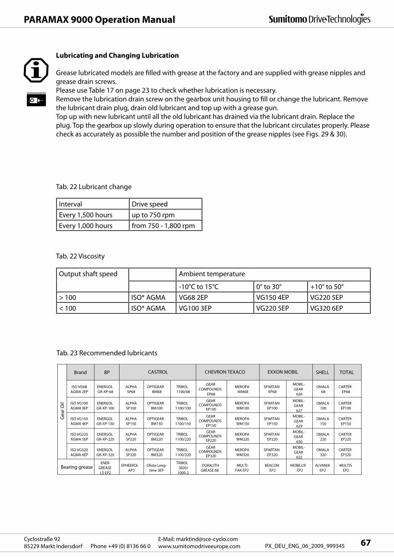
Brand BP SHELL TOTAL
ISO VG68AGMA 2EP
ENERGOLGR-XP-68
ALPHASP68
OPTIGEARBM68
TRIBOL1100/68
GEARCOMPOUNDS
EP68
MEROPAWM68
SPARTANEP68
MOBIL-GEAR
626
OMALA68
CARTEREP68
ISO VG100AGMA 3EP
ENERGOLGR-XP-100
ALPHASP100
OPTIGEARBM100
TRIBOL1100/100
GEARCOMPOUNDS
EP100
MEROPAWM100
SPARTANEP100
MOBIL-GEAR
627
OMALA100
CARTEREP100
ISO VG150AGMA 4EP
ENERGOLGR-XP-150
ALPHASP150
OPTIGEARBM150
TRIBOL1100/150
GEARCOMPOUNDS
EP150
MEROPAWM150
SPARTANEP150
MOBIL-GEAR
629
OMALA150
CARTEREP150
ISO VG220AGMA 5EP
ENERGOLGR-XP-220
ALPHASP220
OPTIGEARBM220
TRIBOL1100/220
GEARCOMPOUNDS
EP220
MEROPAWM220
SPARTANEP220
MOBIL-GEAR
630
OMALA220
CARTEREP220
ISO VG320AGMA 6EP
ENERGOLGR-XP-320
ALPHASP320
OPTIGEARBM320
TRIBOL1100/320
GEARCOMPOUNDS
EP320
MEROPAWM320
SPARTANEP320
MOBIL-GEAR
632
OMALA320
CARTEREP320
ENER-GREASELS EP2
SPHEEROLAP3
Olista Long-time 3EP
TRIBOL3020/
1000-2
DURALITHGREASE 68
MULTI-FAK EP2
BEACONEP2
MOBILUXEP2
ALVANIAEP2
MULTISEP2
EXXON MOBIL
Gea
r Oil
Bearing grease
CASTROL CHEVRON TEXACO
67E-Mail: [email protected]
www.sumitomodriveeurope.comPhone +49 (0) 8136 66 0Cyclostraße 92
85229 Markt Indersdorf PX_DEU_ENG_06_2009_999345
PARAMAX 9000 Operation Manual
Grease lubricated models are filled with grease at the factory and are supplied with grease nipples and
grease drain screws.
Please use Table 17 on page 23 to check whether lubrication is necessary.
Remove the lubrication drain screw on the gearbox unit housing to fill or change the lubricant. Remove
the lubricant drain plug, drain old lubricant and top up with a grease gun.
Top up with new lubricant until all the old lubricant has drained via the lubricant drain. Replace the
plug. Top the gearbox up slowly during operation to ensure that the lubricant circulates properly. Please
check as accurately as possible the number and position of the grease nipples (see Figs. 29 & 30).
Tab. 22 Lubricant change
Tab. 22 Viscosity
Tab. 23 Recommended lubricants
Interval Drive speed
Every 1,500 hours up to 750 rpm
Every 1,000 hours from 750 - 1,800 rpm
Output shaft speed Ambient temperature
-10°C to 15°C 0° to 30° +10° to 50°
> 100 ISO* AGMA VG68 2EP VG150 4EP VG220 5EP
< 100 ISO* AGMA VG100 3EP VG220 5EP VG320 6EP
Lubricating and Changing Lubrication
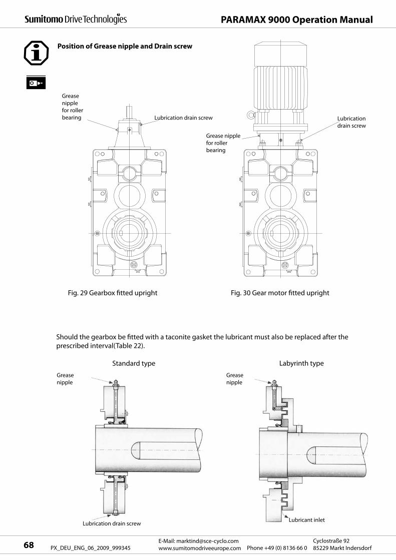
PARAMAX 9000 Operation Manual
E-Mail: [email protected]
www.sumitomodriveeurope.com Phone +49 (0) 8136 66 0Cyclostraße 92
85229 Markt Indersdorf68 PX_DEU_ENG_06_2009_999345
Position of Grease nipple and Drain screw
Grease
nipple
for roller
bearing
Grease
nipple
Grease
nipple
Lubrication
drain screw
Grease nipple
for roller
bearing
Lubrication drain screw
Fig. 29 Gearbox fitted upright Fig. 30 Gear motor fitted upright
Should the gearbox be fitted with a taconite gasket the lubricant must also be replaced after the
prescribed interval(Table 22).
Standard type Labyrinth type
Lubricant inletLubrication drain screw
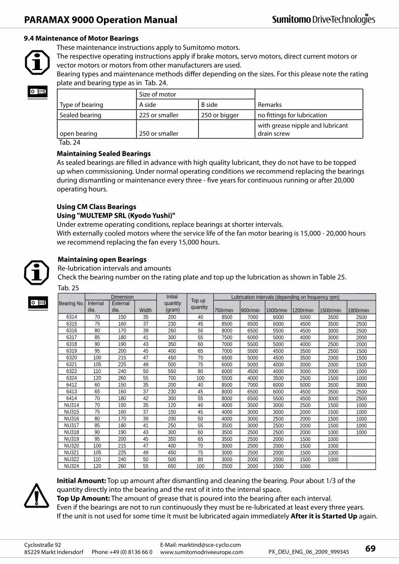
Internal dia.
External dia. Width 750r/min 900r/min 1000r/min 1200r/min 1500r/min 1800r/min
6314 70 150 35 200 40 8500 7000 6000 5000 3500 25006315 75 160 37 230 45 8500 6500 6000 4500 3500 25006316 80 170 39 260 50 8000 6500 5500 4500 3000 25006317 85 180 41 300 55 7500 6000 5000 4000 3000 20006318 90 190 43 350 60 7000 5500 5000 4000 2500 20006319 95 200 45 400 65 7000 5500 4500 3500 2500 15006320 100 215 47 450 70 6500 5000 4500 3500 2000 15006321 105 225 49 500 75 6000 5000 4000 3000 2000 15006322 110 240 50 550 80 6000 4500 4000 3000 2000 10006324 120 260 55 700 100 5500 4000 3500 2500 1500 10006412 60 150 35 200 40 8500 7000 6000 5000 3500 30006413 65 160 37 230 45 8000 6500 6000 4500 3500 25006414 70 180 42 300 55 8000 6500 5500 4500 3000 2500
NU314 70 150 35 120 40 4000 3500 3000 2500 1500 1000NU315 75 160 37 150 45 4000 3000 3000 2000 1500 1000NU316 80 170 39 200 50 4000 3000 2500 2000 1500 1000NU317 85 180 41 250 55 3500 3000 2500 2000 1500 1000NU318 90 190 43 300 60 3500 2500 2500 2000 1000 1000NU319 95 200 45 350 65 3500 2500 2000 1500 1000NU320 100 215 47 400 70 3000 2500 2000 1500 1000NU321 105 225 49 450 75 3000 2500 2000 1500 1000NU322 110 240 50 500 80 3000 2000 2000 1500 1000NU324 120 260 55 650 100 2500 2000 1500 1000
Lubrication intervals (depending on frequency rpm)Initial quantity(gram)
DimensionBearing No. Top up
quantity
69E-Mail: [email protected]
www.sumitomodriveeurope.comPhone +49 (0) 8136 66 0Cyclostraße 92
85229 Markt Indersdorf PX_DEU_ENG_06_2009_999345
PARAMAX 9000 Operation Manual
9.4 Maintenance of Motor Bearings
These maintenance instructions apply to Sumitomo motors.
The respective operating instructions apply if brake motors, servo motors, direct current motors or
vector motors or motors from other manufacturers are used.
Bearing types and maintenance methods differ depending on the sizes. For this please note the rating
plate and bearing type as in Tab. 24.
Tab. 24
Maintaining Sealed Bearings
As sealed bearings are filled in advance with high quality lubricant, they do not have to be topped
up when commissioning. Under normal operating conditions we recommend replacing the bearings
during dismantling or maintenance every three - five years for continuous running or after 20,000
operating hours.
Using CM Class Bearings
Using "MULTEMP SRL (Kyodo Yushi)"
Under extreme operating conditions, replace bearings at shorter intervals.
With externally cooled motors where the service life of the fan motor bearing is 15,000 - 20,000 hours
we recommend replacing the fan every 15,000 hours.
Type of bearing
Size of motor
RemarksA side B side
Sealed bearing 225 or smaller 250 or bigger no fittings for lubrication
open bearing 250 or smaller
with grease nipple and lubricant
drain screw
Maintaining open Bearings
Re-lubrication intervals and amounts
Check the bearing number on the rating plate and top up the lubrication as shown in Table 25.
Initial Amount: Top up amount after dismantling and cleaning the bearing. Pour about 1/3 of the
quantity directly into the bearing and the rest of it into the internal space.
Top Up Amount: The amount of grease that is poured into the bearing after each interval.
Even if the bearings are not to run continuously they must be re-lubricated at least every three years.
If the unit is not used for some time it must be lubricated again immediately After it is Started Up again.
Tab. 25
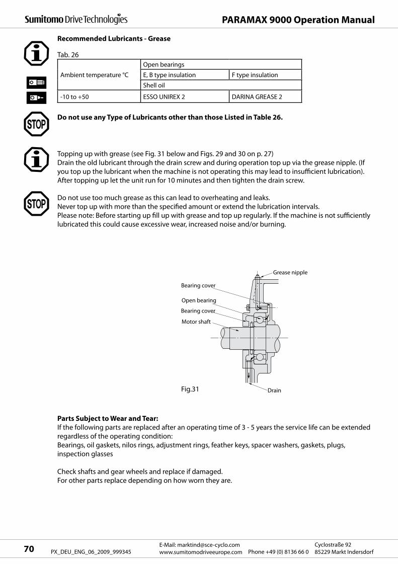
BracketMotor shaft
Open bearing
Bearing cover
Outlet
Grease nipples
PARAMAX 9000 Operation Manual
E-Mail: [email protected]
www.sumitomodriveeurope.com Phone +49 (0) 8136 66 0Cyclostraße 92
85229 Markt Indersdorf70 PX_DEU_ENG_06_2009_999345
Grease nipple
Bearing cover
Open bearing
Bearing cover
Motor shaft
Fig.31 Drain
Recommended Lubricants - Grease
Do not use any Type of Lubricants other than those Listed in Table 26.
Topping up with grease (see Fig. 31 below and Figs. 29 and 30 on p. 27)
Drain the old lubricant through the drain screw and during operation top up via the grease nipple. (If
you top up the lubricant when the machine is not operating this may lead to insufficient lubrication).
After topping up let the unit run for 10 minutes and then tighten the drain screw.
Do not use too much grease as this can lead to overheating and leaks.
Never top up with more than the specified amount or extend the lubrication intervals.
Please note: Before starting up fill up with grease and top up regularly. If the machine is not sufficiently
lubricated this could cause excessive wear, increased noise and/or burning.
Parts Subject to Wear and Tear:
If the following parts are replaced after an operating time of 3 - 5 years the service life can be extended
regardless of the operating condition:
Bearings, oil gaskets, nilos rings, adjustment rings, feather keys, spacer washers, gaskets, plugs,
inspection glasses
Check shafts and gear wheels and replace if damaged.
For other parts replace depending on how worn they are.
Ambient temperature °C
Open bearings
E, B type insulation F type insulation
Shell oil
-10 to +50 ESSO UNIREX 2 DARINA GREASE 2
Tab. 26
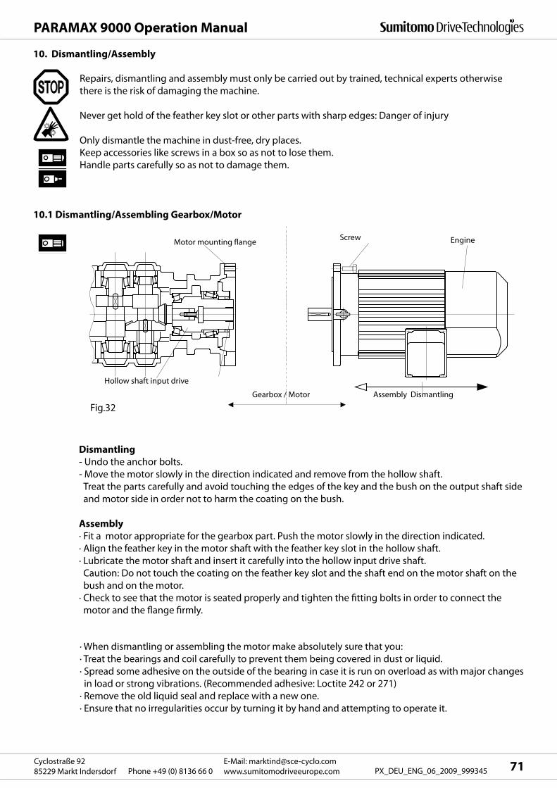
71E-Mail: [email protected]
www.sumitomodriveeurope.comPhone +49 (0) 8136 66 0Cyclostraße 92
85229 Markt Indersdorf PX_DEU_ENG_06_2009_999345
PARAMAX 9000 Operation Manual
10. Dismantling/Assembly
Repairs, dismantling and assembly must only be carried out by trained, technical experts otherwise
there is the risk of damaging the machine.
Never get hold of the feather key slot or other parts with sharp edges: Danger of injury
Only dismantle the machine in dust-free, dry places.
Keep accessories like screws in a box so as not to lose them.
Handle parts carefully so as not to damage them.
10.1 Dismantling/Assembling Gearbox/Motor
Motor mounting flangeScrew Engine
Assembly DismantlingGearbox / Motor
Hollow shaft input drive
Dismantling
- Undo the anchor bolts.
- Move the motor slowly in the direction indicated and remove from the hollow shaft.
Treat the parts carefully and avoid touching the edges of the key and the bush on the output shaft side
and motor side in order not to harm the coating on the bush.
Assembly
· Fit a motor appropriate for the gearbox part. Push the motor slowly in the direction indicated.
· Align the feather key in the motor shaft with the feather key slot in the hollow shaft.
· Lubricate the motor shaft and insert it carefully into the hollow input drive shaft.
Caution: Do not touch the coating on the feather key slot and the shaft end on the motor shaft on the
bush and on the motor.
· Check to see that the motor is seated properly and tighten the fitting bolts in order to connect the
motor and the flange firmly.
· When dismantling or assembling the motor make absolutely sure that you:
· Treat the bearings and coil carefully to prevent them being covered in dust or liquid.
· Spread some adhesive on the outside of the bearing in case it is run on overload as with major changes
in load or strong vibrations. (Recommended adhesive: Loctite 242 or 271)
· Remove the old liquid seal and replace with a new one.
· Ensure that no irregularities occur by turning it by hand and attempting to operate it.
Fig.32
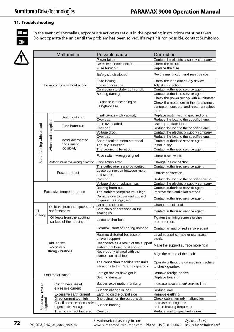
Possible cause CorrectionPower failure. Contact the electricity supply company.Defective electric circuit. Check the circuit.Fuse burnt out. Replace the fuse.
Safety clutch tripped. Rectify malfunction and reset device.
Load locking. Check the load and safety device.Loose connection. Adjust connection.Connection to stator coil cut off. Contact authorised service agent.Bearing damage. Contact authorised service agent.
Check the power supply with a voltmeter.
Insufficient switch capacity. Replace switch with a specified one.Overload. Reduce the load to the specified one.Fuse overloaded. Use appropriate fuse.Overload. Reduce the load to the specified one.Voltage drop. Contact the electricity supply company.Overload. Reduce the load to the specified one.Short-circuited motor stator coil. Contact authorised service agent.The key is missing. Install a key.The bearing is burnt out. Contact authorised service agent.
Fuse switch wrongly aligned Check fuse switch.
Connection error. Change the connection.The outlet wire is short-circuited. Contact authorised service agent.Loose connection between motor and starter. Correct connection.
Overload. Reduce the load to the specified value.Voltage drop or voltage rise. Contact the electricity supply companyBearing burnt out. Contact authorised service agent.The ambient temperature is high. Improve the ventilation method.Damage due to overload applied to gears, bearings, etc. Contact authorised service agent.
Damaged oil seal. Change the oil seal.Scratches or abrasions on the sealing lip. Contact authorised service agent.
Loose anchor bolt. Tighten the fitting screws to their proper torque.
Gearbox, shaft or bearing damage Contact an authorised service agent
Housing distorted because of uneven support
Level support surface or use spacer blocks
Resonance as a result of the support surface not being rigid enough Make the support surface more rigid
Not properly aligned with the connection machine Align the centre of the shaft
The connection machine transmits vibrations to the Paramax gearbox
Operate without the connection machine to check gearbox
Foreign bodies have got in Remove foreign bodiesBearing damage Replace bearing
Sudden acceleration/ braking Increase acceleration/ braking time
Sudden change in load Reduce loadExcessive earth current Earthing on the output side Remove earthingDirect current too high Short circuit on the output side Check cable, remedy malfunctionCut off because of excessive regenerative voltage Sudden braking Increase braking time,
reduce braking frequencyThermo contact triggered Overload Reduce load to specified values
Check the motor, coil in the transformer,contactor, fuse, etc. and repair or replacethem.
Fuse burnt out
Switch gets hot
Fuse burnt out
Motor overheated and running too slowly
Malfunction
Oil leaks from the abutting surface of the housing
Excessive temperature rise
3-phase is functioning as single-phase.
Oil leaks from the input/outputshaft sections.Oil
leakage
The motor runs without a load.
Whe
n lo
ad is
app
lied
Mot
or ru
nnin
g w
ithou
t loa
d
Motor runs in the wrong direction
Odd noises Excessively strong vibrations
Odd motor noise
Cut off because of excessive current
Freq
uenc
y in
verte
r tri
gger
ed
PARAMAX 9000 Operation Manual
E-Mail: [email protected]
www.sumitomodriveeurope.com Phone +49 (0) 8136 66 0Cyclostraße 92
85229 Markt Indersdorf72 PX_DEU_ENG_06_2009_999345
11. Troubleshooting
In the event of anomalies, appropriate action as set out in the operating instructions must be taken.
Do not operate the unit until the problem has been solved. If a repair is not possible, contact Sumitomo.

21
9
24
23
22
11
1 2 3 4 5 6 7 8 9 10 11
19 18 17 16 15 14 1320 12
73E-Mail: [email protected]
www.sumitomodriveeurope.comPhone +49 (0) 8136 66 0Cyclostraße 92
85229 Markt Indersdorf PX_DEU_ENG_06_2009_999345
PARAMAX 9000 Operation Manual
12. Sectional drawings
12.1 PARAMAX Gear Motor Sectional Drawing
Fig. 33 Gear motor with right angle
shaft configuration
Fig. 34 Gear motor with
parallel shafts
Part no. Description Part no. Description Part no. Description
1 Housing 9 Motor mounting flange 17 Cog wheel
2 Cog wheel 10 Oil gasket 18 Adjusting ring
3 Drive shaft 11 Engine 19 Oil gasket
4 Tapered roller bearing 12 Bush 20 Tapered roller bearing
5 Bevel gear 13 Bevel pinion 21 Gear wheel
6 Tapered roller bearing 14 Tapered roller bearing 22 Pinion shaft
7 Tapered roller bearing 15 Pinion shaft 23 Motor adaptor
8 Bearing housing 16 Pinion shaft 24 Coupling
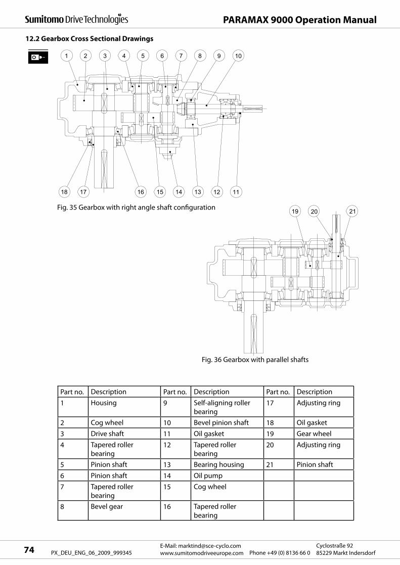
212019
8 9 107654321
13 12 111415161718
PARAMAX 9000 Operation Manual
E-Mail: [email protected]
www.sumitomodriveeurope.com Phone +49 (0) 8136 66 0Cyclostraße 92
85229 Markt Indersdorf74 PX_DEU_ENG_06_2009_999345
12.2 Gearbox Cross Sectional Drawings
Fig. 35 Gearbox with right angle shaft configuration
Fig. 36 Gearbox with parallel shafts
Part no. Description Part no. Description Part no. Description
1 Housing 9 Self-aligning roller
bearing17 Adjusting ring
2 Cog wheel 10 Bevel pinion shaft 18 Oil gasket
3 Drive shaft 11 Oil gasket 19 Gear wheel
4 Tapered roller
bearing12 Tapered roller
bearing20 Adjusting ring
5 Pinion shaft 13 Bearing housing 21 Pinion shaft
6 Pinion shaft 14 Oil pump
7 Tapered roller
bearing15 Cog wheel
8 Bevel gear 16 Tapered roller
bearing
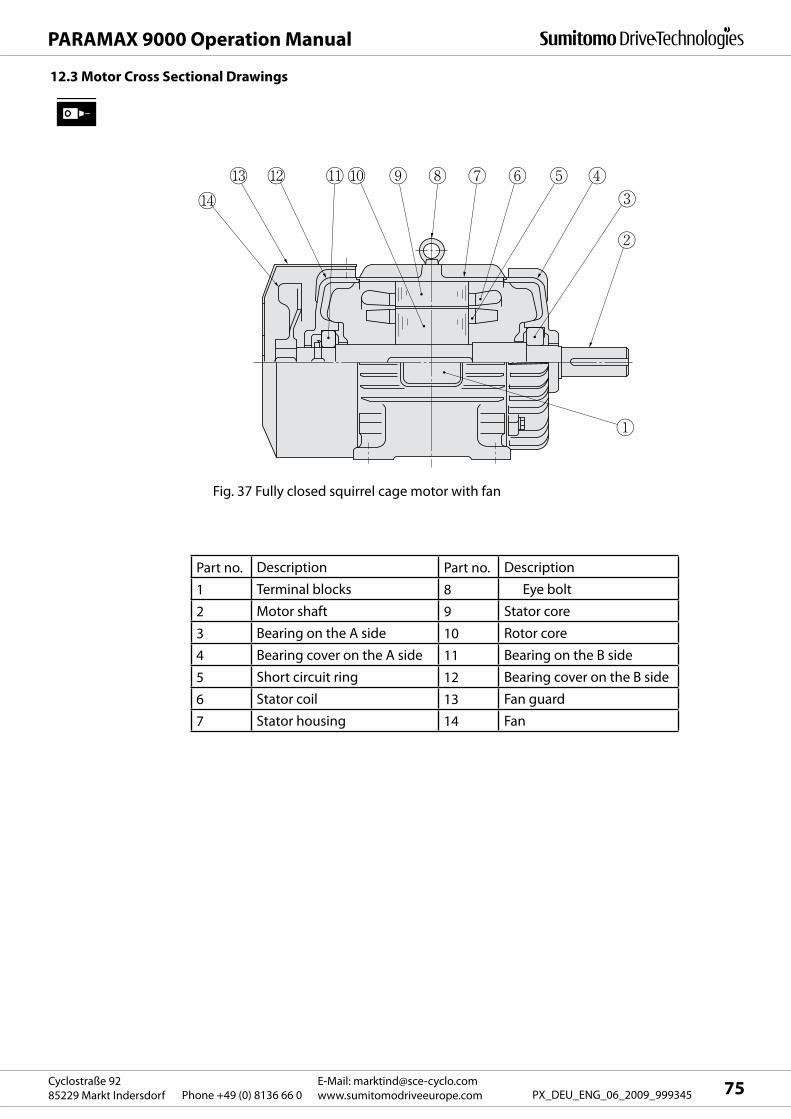
75E-Mail: [email protected]
www.sumitomodriveeurope.comPhone +49 (0) 8136 66 0Cyclostraße 92
85229 Markt Indersdorf PX_DEU_ENG_06_2009_999345
PARAMAX 9000 Operation Manual
Part no. Description Part no. Description
1 Terminal blocks 8 Eye bolt
2 Motor shaft 9 Stator core
3 Bearing on the A side 10 Rotor core
4 Bearing cover on the A side 11 Bearing on the B side
5 Short circuit ring 12 Bearing cover on the B side
6 Stator coil 13 Fan guard
7 Stator housing 14 Fan
12.3 Motor Cross Sectional Drawings
Fig. 37 Fully closed squirrel cage motor with fan
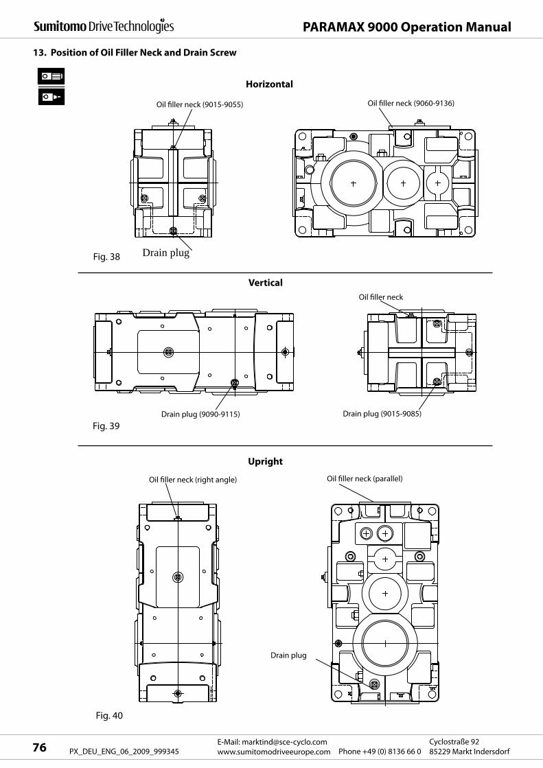
PARAMAX 9000 Operation Manual
E-Mail: [email protected]
www.sumitomodriveeurope.com Phone +49 (0) 8136 66 0Cyclostraße 92
85229 Markt Indersdorf76 PX_DEU_ENG_06_2009_999345
13. Position of Oil Filler Neck and Drain Screw
Horizontal
Vertical
Upright
Fig. 38 Drain plug
Oil filler neck
Oil filler neck (parallel)Oil filler neck (right angle)
Fig. 40
Fig. 39
Drain plug (9090-9115)
Oil filler neck (9060-9136)Oil filler neck (9015-9055)
Drain plug (9015-9085)
Drain plug
77E-Mail: [email protected]
www.sumitomodriveeurope.comPhone +49 (0) 8136 66 0Cyclostraße 92
85229 Markt Indersdorf PX_DEU_ENG_06_2009_999345
PARAMAX 9000 Operation Manual
Explosive gas mixtures or dust concentrations combined with hot, live, moving gearbox parts may lead
to serious material and physical damage or even fatal injuries.
Standard PARAMAX gearboxes and gear motors must not be used in an area where there is a risk of
explosion.
Under such conditions special explosion-proof gearboxes or gear motors must be used.
An ATEX certified gearbox or an ATEX certified gear motor must always have an ATEX label attached at
the factory. The ATEX identification mark is found on the rating plate (see Section 3.1).
Installing, connecting, commissioning and maintenance and repair work on the gearbox/ gear motor
and on additional electrical equipment must only be carried out by a qualified professional, taking
account of:
- these instructions
- the warning and instruction plates on the gearbox/ gear motor
- any other development documents and connection diagrams relating to the drive
- the plant-specific conditions and requirements,
- the national and regional standards and regulations in force (explosion protection, safety, accident
protection)
- dust deposits must be no thicker than 1mm and must be removed if necessary.
- The installation site at the customer's premises must not prevent the heat discharging from the
gearbox as a result of convection and heat conduction.
- Overloaded operation is not permitted.
- Heat must not get into the gearbox from outside.
- The oil temperature must not exceed a max. of 85°C.
- The drive speed must not exceed a max. of 1800 r/min.
- All electrical and mechanical components fitted to the gearbox must have a separate ATEX certificate.
As the inverter itself is not explosion-proof, explosion-proof, inverter-driven motors must also only be
installed in an area that is free from explosive gas mixtures or dust concentrations. Otherwise electric
shocks, injuries, explosions or damage to the equipment may occur.
14.1 Safety Instructions for Use in an ATEX Area
14 Special Instructions for ATEX approved PARAMAX Gearboxes and Gear Motors
Electrical Installation of an Explosion-Proof Motor (ATEX)
The supply of an explosion-proof motor must comply with the electrical codes supplied by the factory,
connection conditions and the explosion protection regulations as well as the operating instructions
otherwise there is the risk of electric shocks, injuries, explosions, fire or damage to the equipment.
With the electrical connection the electrical markings provided by the factory, the electrical conditions
and the explosion protection regulations must be obeyed otherwise there is the risk of burns, electric
shocks, injuries and fire.
An overload protective device must be used for explosion-proof motors that switches the unit off after a
specific time interval if the motor is blocked.
If an inverter is used for an explosion-proof motor one inverter must be used for each motor. Only
use approved inverters.
When measuring the insulation resistance on an explosion-proof motor you must ensure that there
is no gas, fumes or other explosive substances around in order to avoid an explosion or ignition.

PARAMAX 9000 Operation Manual
E-Mail: [email protected]
www.sumitomodriveeurope.com Phone +49 (0) 8136 66 0Cyclostraße 92
85229 Markt Indersdorf78 PX_DEU_ENG_06_2009_999345
- Does the information on the gearbox or gear motor rating plate correspond with the ATEX area of
application required on site?
- Does the rating plate have the correct information?
- Is the drive undamaged (check for any transport or storage damage)?
- Is an unrestricted supply of cooling air guaranteed? Is any hot exhaust air being drawn in from other
equipment? The cooling air must not exceed a temperature of 40°C.
- Are all inputs and outputs and all electrical parts ATEX approved and are they also labelled correctly?
The gearbox must be switched on without load when first commissioned. If it runs quietly and without
any odd noises, the gearbox is attached to the driven machine.
Measure the surface temperature after about 3 hours. Check the maximum permissible difference
between the surface temperature and the ambient temperature. Should this value be greater than that
specified for the relevant type the equipment must be stopped immediately and Sumitomo must be
contacted.
For applications in ATEX areas PARAMAX gearboxes are designed at the factory so that the oil
temperature never exceeds 85°C under any circumstances. This must also be guaranteed by the
operator in the relevant application.
The oil temperature in the equipment is always tested under full load.
14.2 Check list for ATEX approved Gearboxes and Gear Motors before Commissioning
Is the PT100 temperature device installed in ATEX gearboxes connected properly?
An isolation amplifier must be provided for sensors and passive components.
Here all the wiring must be done with light blue connection components.
ATEX ID ATEX classification
PARAMAX rating plate with ATEX ID
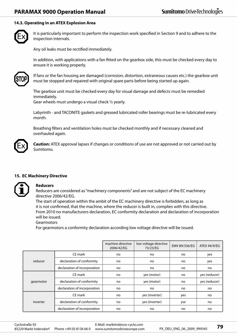
79E-Mail: [email protected]
www.sumitomodriveeurope.comPhone +49 (0) 8136 66 0Cyclostraße 92
85229 Markt Indersdorf PX_DEU_ENG_06_2009_999345
PARAMAX 9000 Operation Manual
It is particularly important to perform the inspection work specified in Section 9 and to adhere to the
inspection intervals.
Any oil leaks must be rectified immediately.
In addition, with applications with a fan fitted on the gearbox side, this must be checked every day to
ensure it is working properly.
If fans or the fan housing are damaged (corrosion, distortion, extraneous causes etc.) the gearbox unit
must be stopped and repaired with original spare parts before being started up again.
The gearbox unit must be checked every day for visual damage and defects must be remedied
immediately.
Gear wheels must undergo a visual check ½ yearly.
Labyrinth - and TACONITE gaskets and greased lubricated roller bearings must be re-lubricated every
month.
Breathing filters and ventilation holes must be checked monthly and if necessary cleaned and
overhauled again.
Caution: ATEX approval lapses if changes or conditions of use are not approved or not carried out by
Sumitomo.
14.3. Operating in an ATEX Explosion Area
Reducers
Reducers are considered as “machinery components” and are not subject of the EC machinery
directive 2006/42/EG.
The start of operation within the ambit of the EC machinery directive is forbidden, as long as
it is not confirmed, that the machine, where the reducer is built in, complies with this directive.
From 2010 no manufacturers declaration, EC conformity declaration and declaration of incorporation
will be issued.
Gearmotors
For gearmotors a conformity declaration according low voltage directive will be issued.
15. EC Machinery Directive
machine directive
2006/42/EG
low voltage directive
73/23/EGEMV 89/336/EG ATEX 94/9/EG
reducer
CE mark no no no yes
declaration of conformity no no no yes
declaration of incorporation no no no no
gearmotor
CE mark no yes (motor) no yes (reducer)
declaration of conformity no yes (motor) no yes (reducer)
declaration of incorporation no no no no
inverter
CE mark no yes (inverter) yes no
declaration of conformity no yes (inverter) yse no
declaration of incorporation no no no no

Worldwide locations
Spain
SM-Cyclo Iberia
C/Landabarri no. 4
Escalera 1 – 2.0 Izqda
48940 Leioa, Vizcaya
Spain
Tel. +34 (0) 94 48 05 38 9
Fax +34 (0) 94 48 01 55 0
Sweden
SM-Cyclo Scandinavia AB
Ridbanegatan 4
21377 Malmö
Sweden
Tel. +46 (0) 40 22 00 30
Fax +46 (0) 40 22 00 35
United Kingdom
SM-Cyclo UK, Ltd.
Unit 29, Bergen Way,
Sutton Fields Industrial Estate
Kingston upon Hull
HU7 0YQ, East Yorkshire
United Kingdom
Tel. +44 (0) 14 82 79 03 40
Fax +44 (0) 14 82 79 03 21
Sumitomo (SHI) Cyclo Drive Germany GmbH
Austria
Gruentalerstraße 30 A
4020 Linz
Austria
Tel. +43 (0) 732 33 09 58
Fax: +43 (0) 732 33 19 78
Benelux
Heikneuterlaan 23
3010 Kessel-Lo/ Leuven
Belgium
Tel. +32 (0) 16 60 83 11
Fax: +32 (0) 16 57 16 39
France
SM-Cyclo France
65-75 Avenue Jean Mermoz
Espace Primagaz
93126 La Courneuve
France
Tel. +33 (1) 49 92 94 94
Fax +33 (1) 49 92 94 90
Italy
SM-Cyclo Italy S.R.L
Via dell ‘Artigianato 23
20010 Cornaredo (MI)
Italy
Tel. +39 (0) 2 93 56 21 21
Fax +39 (0) 2 93 56 98 93
Europe
Germany
Sumitomo (SHI) Cyclo Drive Germany GmbH
European Headquarters
Cyclostraße 92
85229 Markt Indersdorf
Germany
Tel. +49 (0) 81 36 66-0
Fax +49 (0) 81 36 57 71
E-Mail: [email protected]
www.sumitomodriveeurope.com
Headquarters & Manufacturing
EUROPE
Sumitomo Heavy Industries Ltd.
PTC Group
Think Park Tower, 1-1
Osaki 2-chome,
Shinagawa-ku, Tokyo 141-6025
www.cyclo.shi.co.jp
World Headquarters
JAPANSumitomo Drive Technologies
Sumitomo Machinery Corp. of America
4200 Holland Boulevard
Chesapeake, VA 23323
Tel: +1 (757) 4 85 33 55
Fax: +1 (757) 4 87 31 93
www.smcyclo.com
Headquarters & Manufacturing
USA
PX
_D
EU
_E
NG
_0
6_
09
_9
99
34
5
Recommended