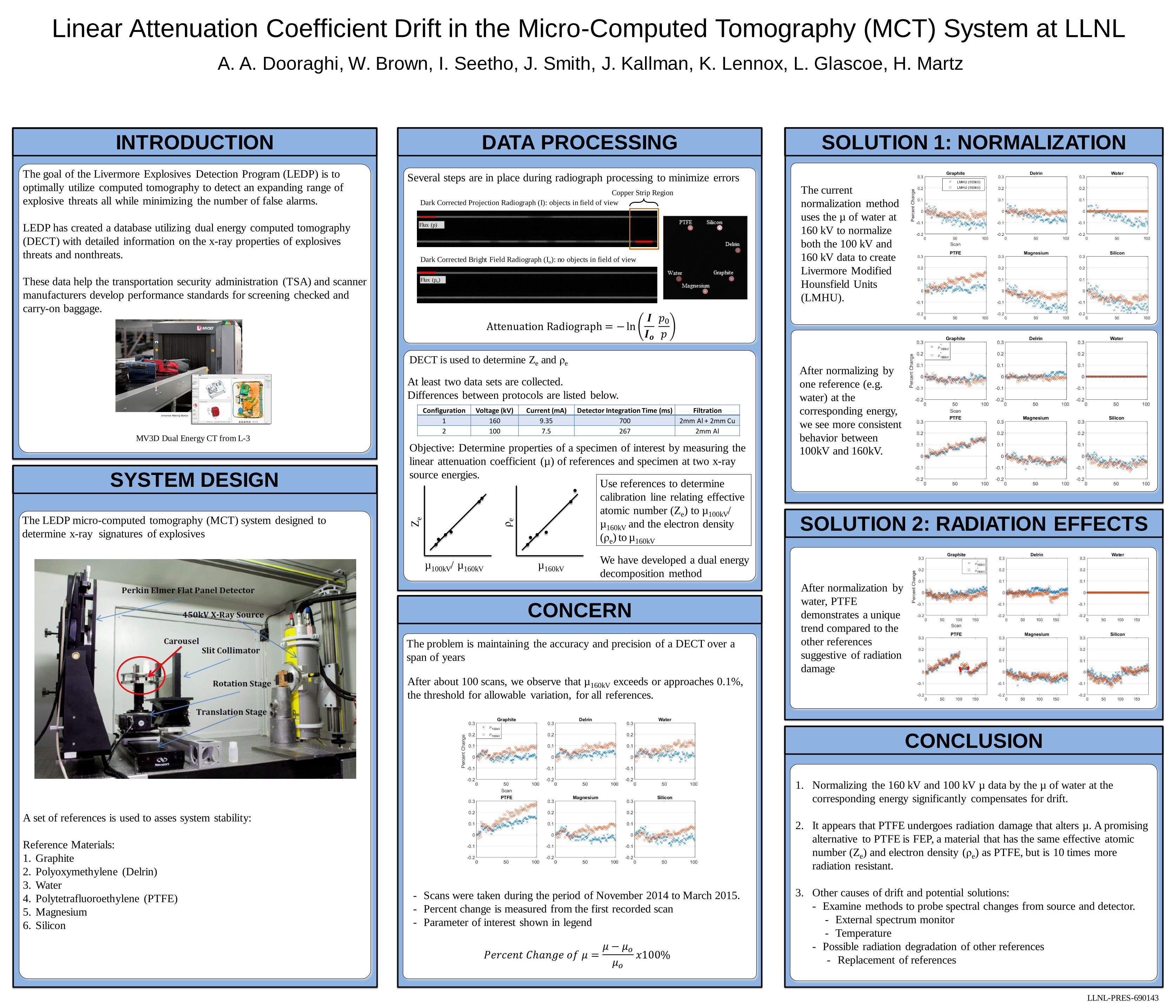
Linear Attenuation Coefficient Drift in the Micro-Computed Tomography (MCT) System at LLNL
A. A. Dooraghi, W. Brown, I. Seetho, J. Smith, J. Kallman, K. Lennox, L. Glascoe, H. Martz
DATA PROCESSING
DECT is used to determine Ze and ρe
Several steps are in place during radiograph processing to minimize errors
CONCERN
The problem is maintaining the accuracy and precision of a DECT over a
span of years
CONCLUSION
1. Normalizing the 160 kV and 100 kV µ data by the µ of water at the
corresponding energy significantly compensates for drift.
2. It appears that PTFE undergoes radiation damage that alters µ. A promising
alternative to PTFE is FEP, a material that has the same effective atomic
number (Ze) and electron density (ρe) as PTFE, but is 10 times more
radiation resistant.
3. Other causes of drift and potential solutions:
- Examine methods to probe spectral changes from source and detector.
- External spectrum monitor
- Temperature
- Possible radiation degradation of other references
- Replacement of references
INTRODUCTION
The goal of the Livermore Explosives Detection Program (LEDP) is to
optimally utilize computed tomography to detect an expanding range of
explosive threats all while minimizing the number of false alarms.
LEDP has created a database utilizing dual energy computed tomography
(DECT) with detailed information on the x-ray properties of explosives
threats and nonthreats.
These data help the transportation security administration (TSA) and scanner
manufacturers develop performance standards for screening checked and
carry-on baggage.
LLNL-PRES-690143
MV3D Dual Energy CT from L-3
The LEDP micro-computed tomography (MCT) system designed to
determine x-ray signatures of explosives
A set of references is used to asses system stability:
Reference Materials:
1. Graphite
2. Polyoxymethylene (Delrin)
3. Water
4. Polytetrafluoroethylene (PTFE)
5. Magnesium
6. Silicon
Copper Strip Region
Dark Corrected Projection Radiograph (I): objects in field of view
Dark Corrected Bright Field Radiograph (Io): no objects in field of view
Flux (p)
Flux (po)
Attenuation Radiograph = − ln𝑰
𝑰𝒐 𝑝0
𝑝
At least two data sets are collected.
Differences between protocols are listed below.
Configuration Voltage (kV) Current (mA) Detector Integration Time (ms) Filtration
1 160 9.35 700 2mm Al + 2mm Cu
2 100 7.5 267 2mm Al
Objective: Determine properties of a specimen of interest by measuring the
linear attenuation coefficient (µ) of references and specimen at two x-ray
source energies.
µ100kV/ µ160kV
Ze
Use references to determine
calibration line relating effective
atomic number (Ze) to µ100kV/
µ160kV and the electron density
(ρe) to µ160kV
µ160kV
ρe
We have developed a dual energy
decomposition method
After about 100 scans, we observe that µ160kV exceeds or approaches 0.1%,
the threshold for allowable variation, for all references.
- Scans were taken during the period of November 2014 to March 2015.
- Percent change is measured from the first recorded scan
- Parameter of interest shown in legend
𝑃𝑒𝑟𝑐𝑒𝑛𝑡 𝐶ℎ𝑎𝑛𝑔𝑒 𝑜𝑓 𝜇 =𝜇 − 𝜇𝑜
𝜇𝑜𝑥100%
SYSTEM DESIGN
𝑃𝑒𝑟𝑐𝑒𝑛𝑡 𝐶ℎ𝑎𝑛𝑔𝑒 𝑜𝑓 𝜇 =𝜇 − 𝜇𝑜
𝜇𝑜𝑥100%
SOLUTION 1: NORMALIZATION
The current
normalization method
uses the µ of water at
160 kV to normalize
both the 100 kV and
160 kV data to create
Livermore Modified
Hounsfield Units
(LMHU).
After normalizing by
one reference (e.g.
water) at the
corresponding energy,
we see more consistent
behavior between
100kV and 160kV.
SOLUTION 2: RADIATION EFFECTS
After normalization by
water, PTFE
demonstrates a unique
trend compared to the
other references
suggestive of radiation
damage
Recommended