Matrix Decompositions and
Quantum Circuit Design
Stephen S. Bullock(joint with Vivek V.Shende,Igor L.Markov, U.M. EECS)
Mathematical andComputational Sciences Division
Division SeminarNational Institute of Standards and Technology
September 15, 2004
1
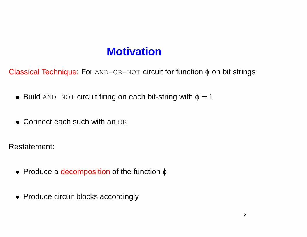
Motivation
Classical Technique: For AND-OR-NOT circuit for function ϕ on bit strings
� Build AND-NOT circuit firing on each bit-string with ϕ � 1
� Connect each such with an OR
Restatement:
� Produce a decomposition of the function ϕ
� Produce circuit blocks accordingly
2
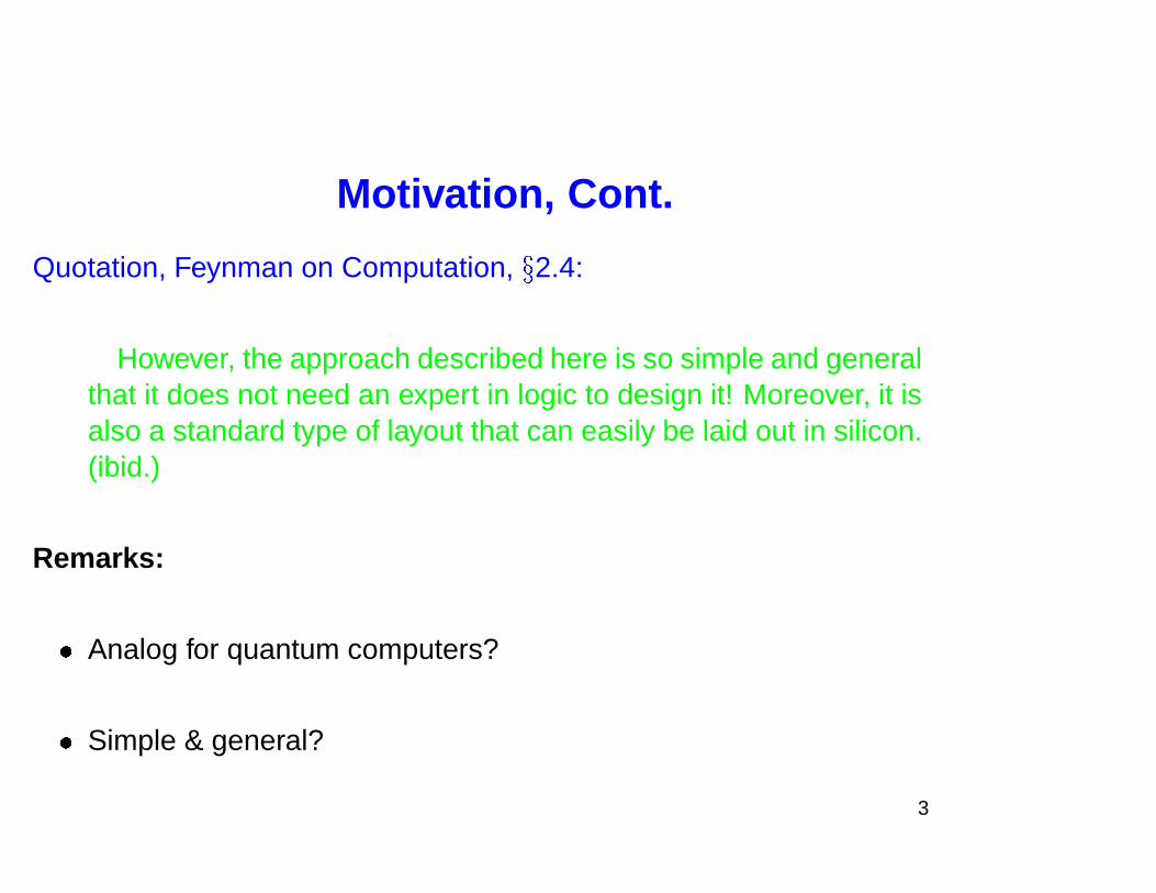
Motivation, Cont.
Quotation, Feynman on Computation,
�
2.4:
However, the approach described here is so simple and generalthat it does not need an expert in logic to design it! Moreover, it isalso a standard type of layout that can easily be laid out in silicon.(ibid.)
Remarks:
� Analog for quantum computers?
� Simple & general?
3
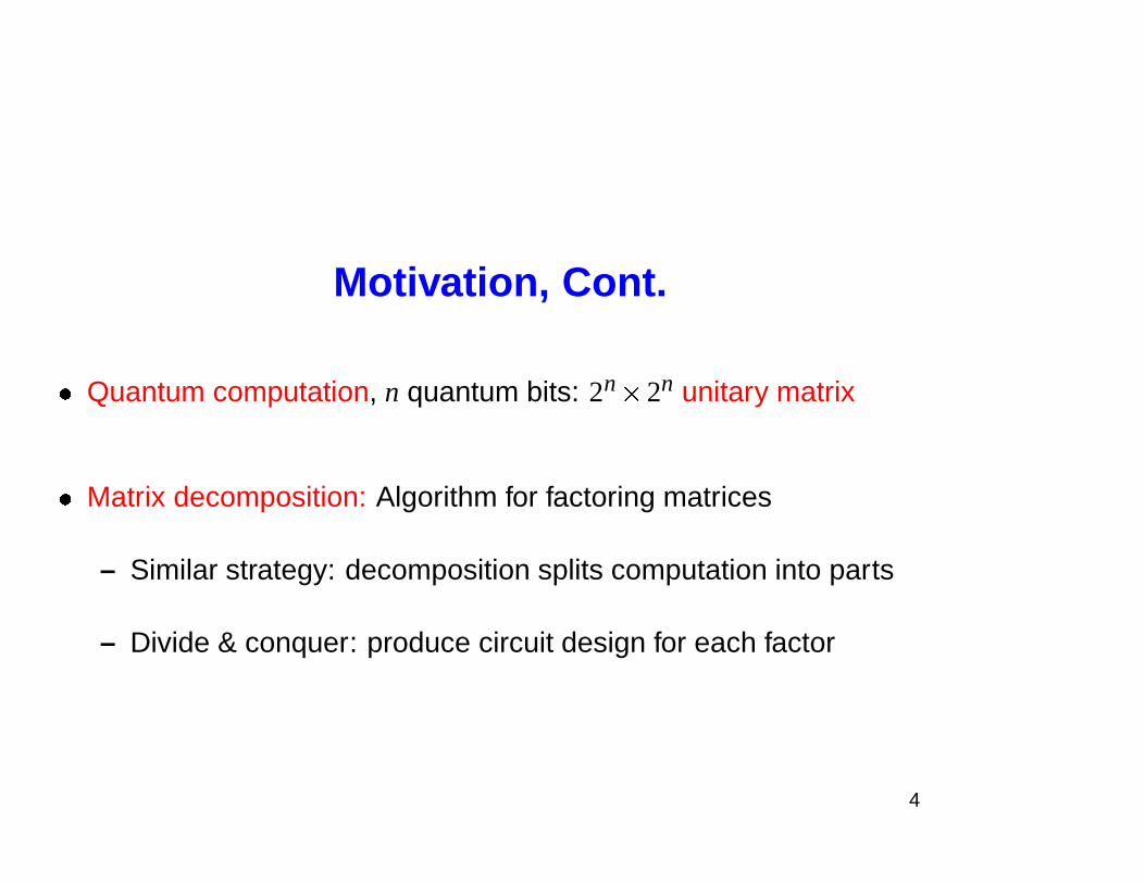
Motivation, Cont.
� Quantum computation, n quantum bits: 2n
� 2n unitary matrix
� Matrix decomposition: Algorithm for factoring matrices
– Similar strategy: decomposition splits computation into parts
– Divide & conquer: produce circuit design for each factor
4
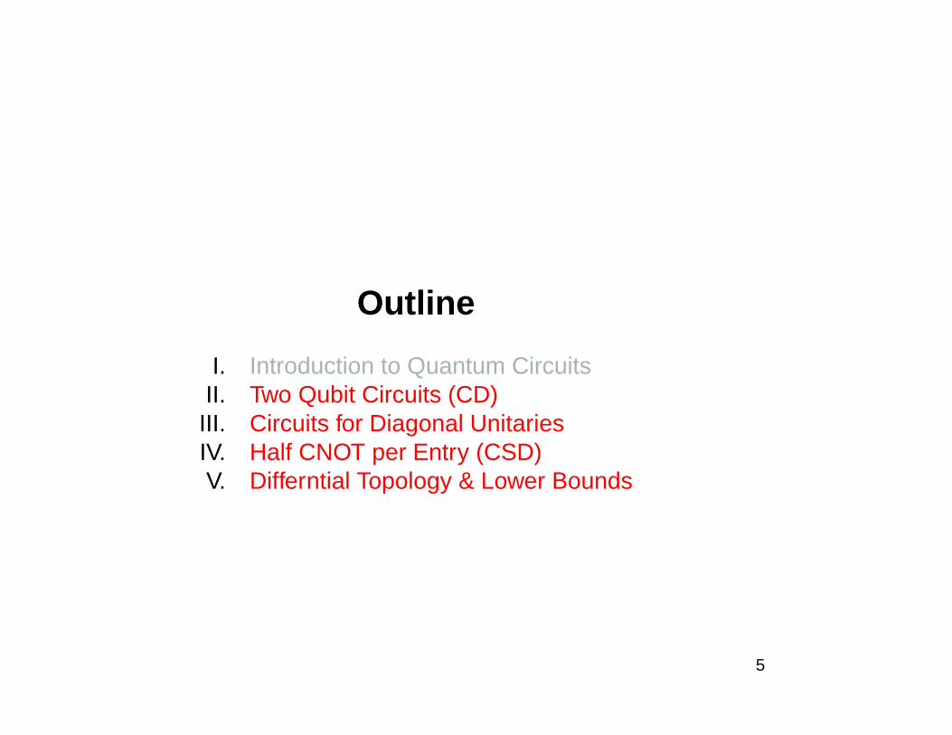
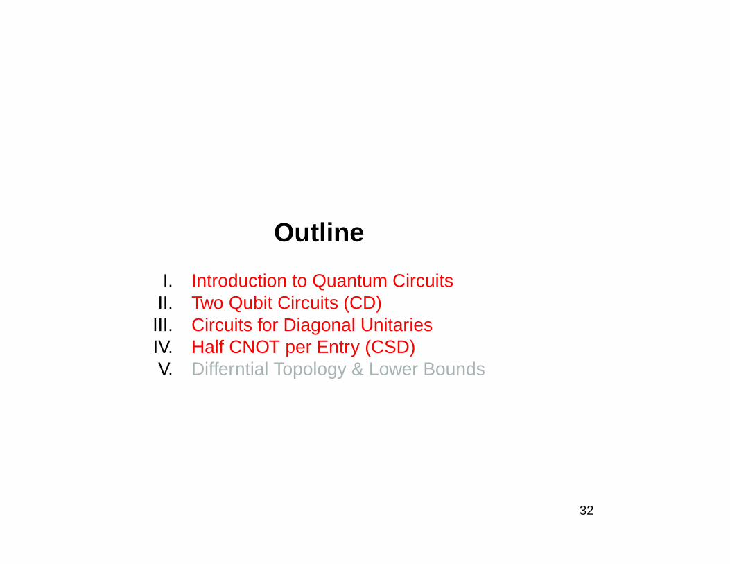
Outline
I. Introduction to Quantum CircuitsII. Two Qubit Circuits (CD)
III. Circuits for Diagonal UnitariesIV. Half CNOT per Entry (CSD)V. Differntial Topology & Lower Bounds
5
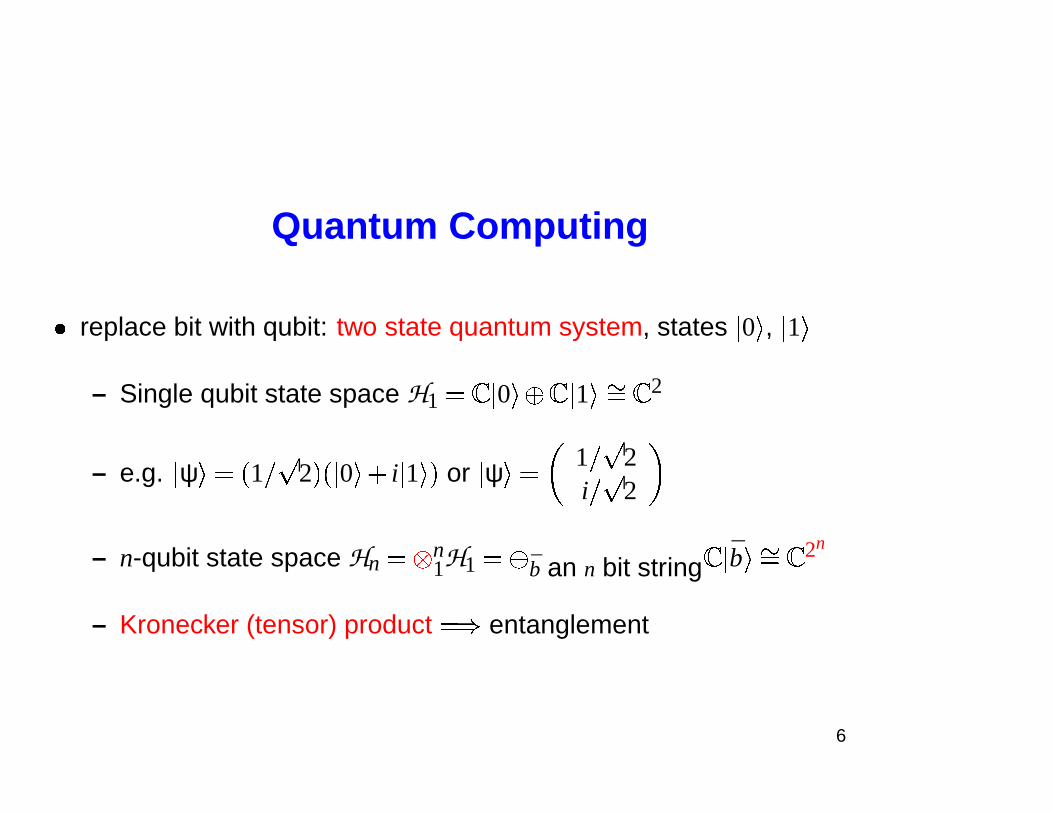
Quantum Computing
� replace bit with qubit: two state quantum system, states � 0 � , � 1 �
– Single qubit state space H1 � � � 0 ��� � � 1 ��� � � 2
– e.g. � ψ � � � 1 � 2 � � � 0 ��� i � 1 � � or � ψ � �
1 � 2i � 2
– n-qubit state space Hn � n1H1 � � b an n bit string � � b �� � � 2n
– Kronecker (tensor) product � � entanglement
6
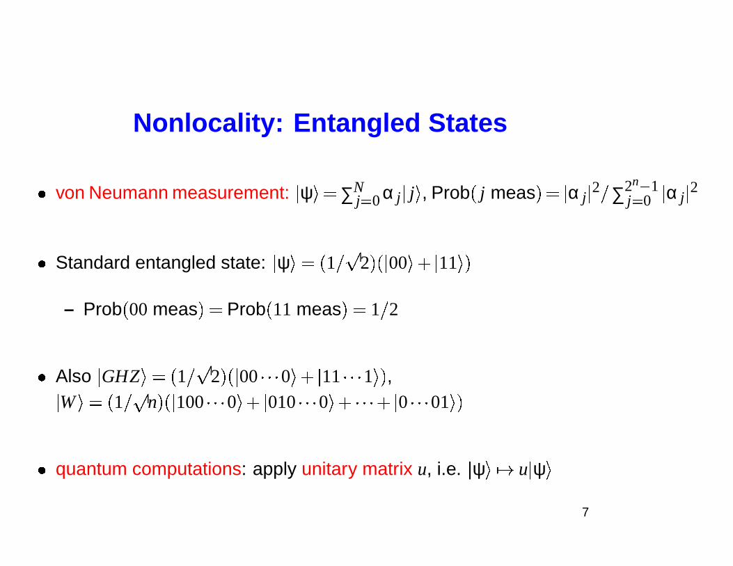
Nonlocality: Entangled States
� von Neumann measurement: � ψ � � ∑Nj� 0 α j � j � , Prob � j meas � � � α j � 2 � ∑2n � 1
j� 0 � α j � 2
� Standard entangled state: � ψ � � � 1 � 2 � � � 00 � � � 11 � �
– Prob � 00 meas � � Prob � 11 meas � � 1 � 2
� Also � GHZ � � � 1 � 2 � � � 00 � � � 0 ��� � 11 � � � 1 � � ,
�W � � � 1 � n � � � 100 � � � 0 ��� � 010 � � � 0 ��� � � �� � 0 � � � 01 � �
� quantum computations: apply unitary matrix u, i.e. � ψ ��� � u � ψ �7
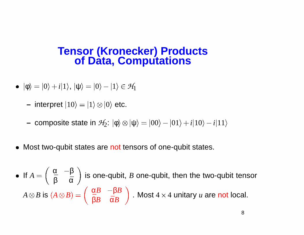
Tensor (Kronecker) Productsof Data, Computations
� � φ � � � 0 ��� i � 1 � , � ψ � � � 0 ��� � 1 ��� H1
– interpret � 10 � � � 1 � � 0 � etc.
– composite state in H2: � φ � � ψ � � � 00 � � � 01 ��� i � 10 ��� i � 11 �
� Most two-qubit states are not tensors of one-qubit states.
� If A �
α � ββ α is one-qubit, B one-qubit, then the two-qubit tensor
A B is � A B � �
αB � βBβB αB
. Most 4 � 4 unitary u are not local.
8
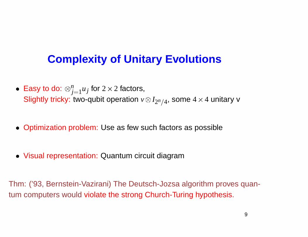
Complexity of Unitary Evolutions
� Easy to do: nj� 1u j for 2 � 2 factors,
Slightly tricky: two-qubit operation v I2n
�
4, some 4 � 4 unitary v
� Optimization problem: Use as few such factors as possible
� Visual representation: Quantum circuit diagram
Thm: (’93, Bernstein-Vazirani) The Deutsch-Jozsa algorithm proves quan-tum computers would violate the strong Church-Turing hypothesis.
9
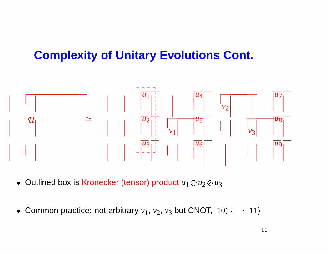
Complexity of Unitary Evolutions Cont.
U
u1 u4
v2
u7
�� u2
v1
u5
v3
u8
u3 u6 u9
_ _ _ _�
�
�
�
�
�
�
�
�
�
�
�
�
�
�
�
�
�
�
�
�
�
�
�
�
�
�
�
�
�
�
�
_ _ _ _
� Outlined box is Kronecker (tensor) product u1 u2 u3
� Common practice: not arbitrary v1, v2, v3 but CNOT, � 10 � � � � 11 �
10
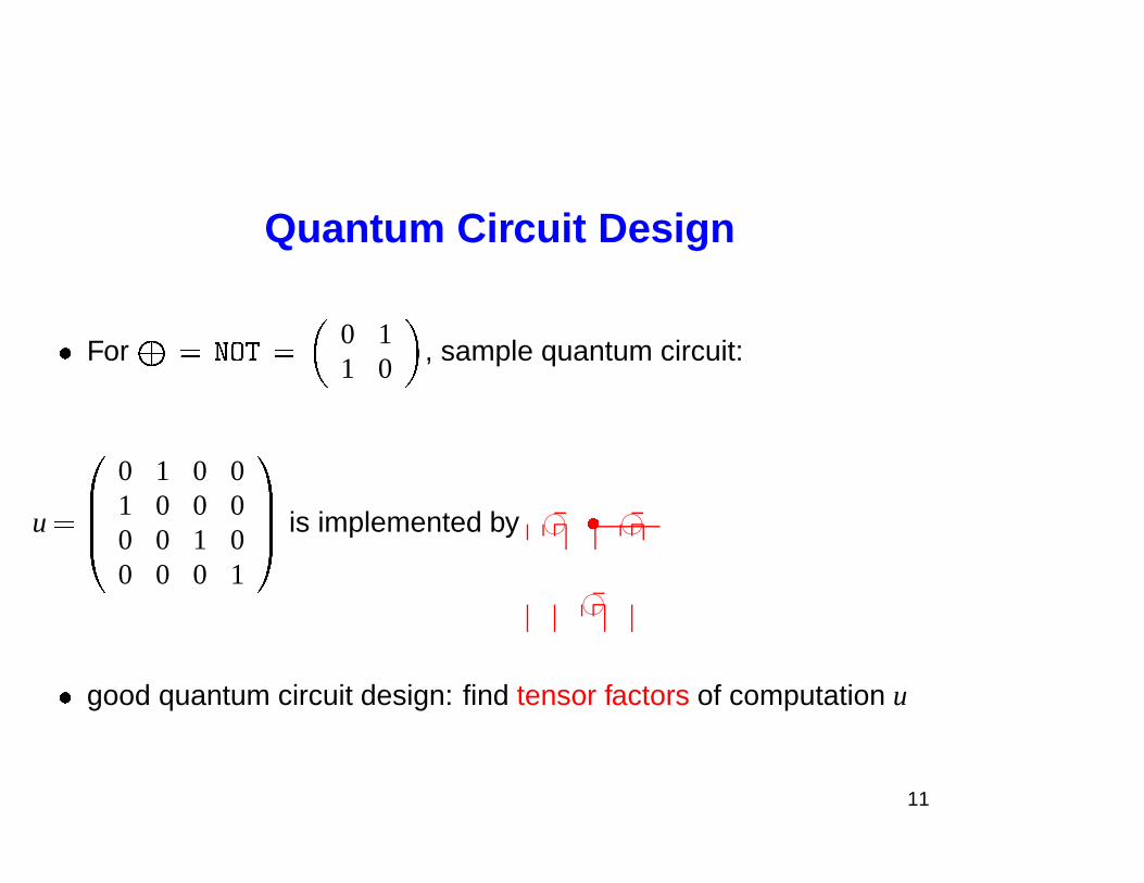
Quantum Circuit Design
� For � � � �� �
0 11 0
, sample quantum circuit:
u � ��
0 1 0 01 0 0 00 0 1 00 0 0 1
�� is implemented by 76540123 � 76540123
76540123
� good quantum circuit design: find tensor factors of computation u
11
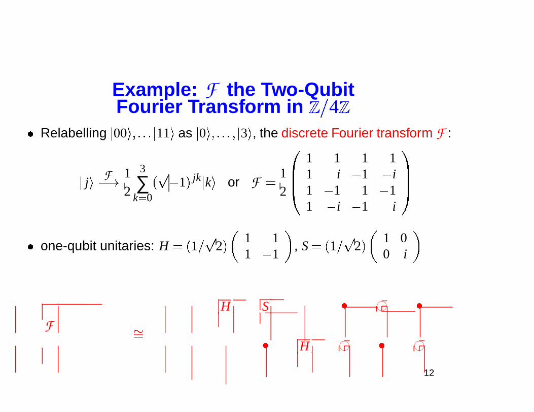
Example: F the Two-QubitFourier Transform in � � 4 �
� Relabelling � 00 ���� � � � 11 � as � 0 ���� � � � � 3 � , the discrete Fourier transform F :
� j �
F
� � 12
3
∑k� 0
� � 1 � jk � k � or F �
12
��
1 1 1 11 i � 1 � i1 � 1 1 � 11 � i � 1 i
��
� one-qubit unitaries: H � � 1 � 2 �1 11 � 1
, S � � 1 � 2 �
1 00 i
FH S � 76540123 �
��
� H 76540123 � 76540123
12
Outline
I. Introduction to Quantum CircuitsII. Two Qubit Circuits (CD)
III. Circuits for Diagonal UnitariesIV. Half CNOT per Entry (CSD)V. Differntial Topology & Lower Bounds
13
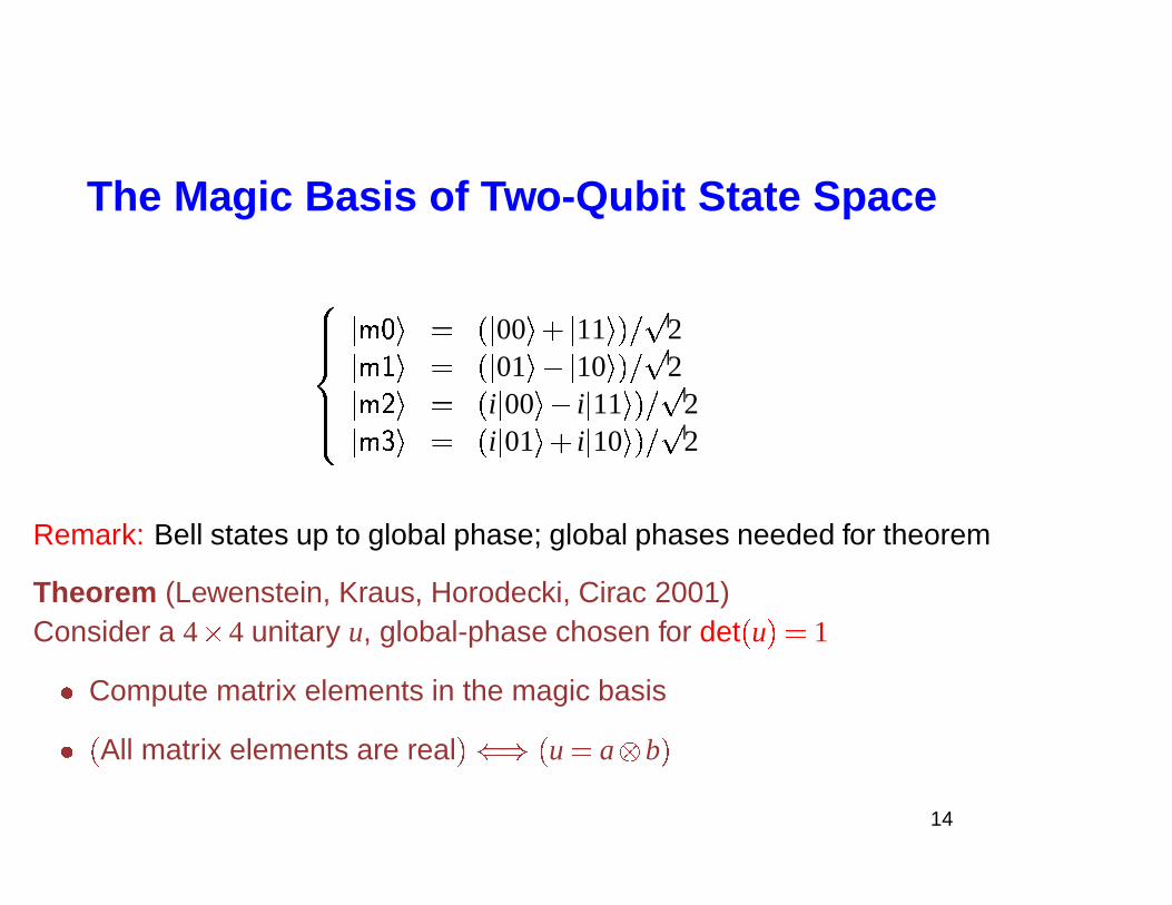
The Magic Basis of Two-Qubit State Space
� ���� ���
���� � � � � � 00 � � � 11 � � � 2
��� � � � � � 01 � � � 10 � � � 2��� � � � � i � 00 � � i � 11 � � � 2
��� � � � i � 01 � � i � 10 � � � 2
Remark: Bell states up to global phase; global phases needed for theorem
Theorem (Lewenstein, Kraus, Horodecki, Cirac 2001)Consider a 4 � 4 unitary u, global-phase chosen for det � u � � 1
� Compute matrix elements in the magic basis
� � All matrix elements are real �� � � u � a b �
14
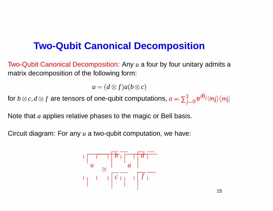
Two-Qubit Canonical Decomposition
Two-Qubit Canonical Decomposition: Any u a four by four unitary admits amatrix decomposition of the following form:
u � � d f � a � b c �
for b c� d f are tensors of one-qubit computations, a � ∑3j� 0 eiθ j ��� � � � � � �
Note that a applies relative phases to the magic or Bell basis.
Circuit diagram: For any u a two-qubit computation, we have:
u
b
a
d
��
c f
15
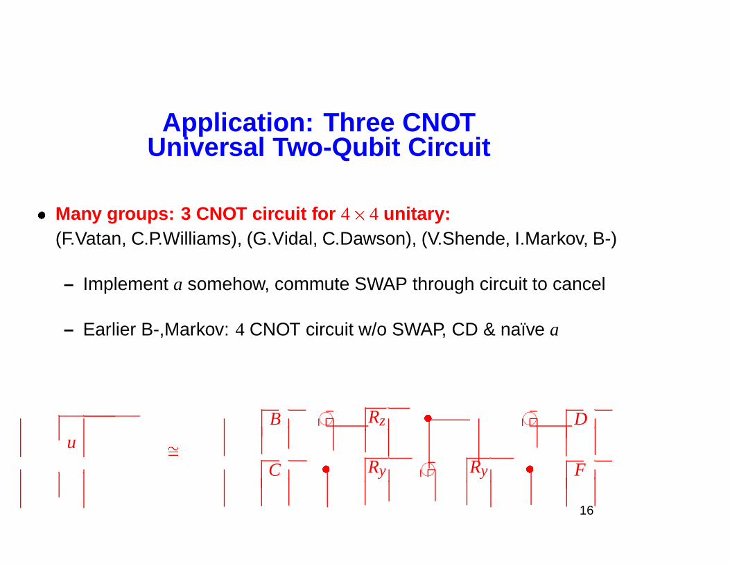
Application: Three CNOTUniversal Two-Qubit Circuit
� Many groups: 3 CNOT circuit for 4 � 4 unitary:(F.Vatan, C.P.Williams), (G.Vidal, C.Dawson), (V.Shende, I.Markov, B-)
– Implement a somehow, commute SWAP through circuit to cancel
– Earlier B-,Markov: 4 CNOT circuit w/o SWAP, CD & naıve a
uB 76540123 Rz � 76540123 D
��
C � Ry 76540123 Ry � F
16
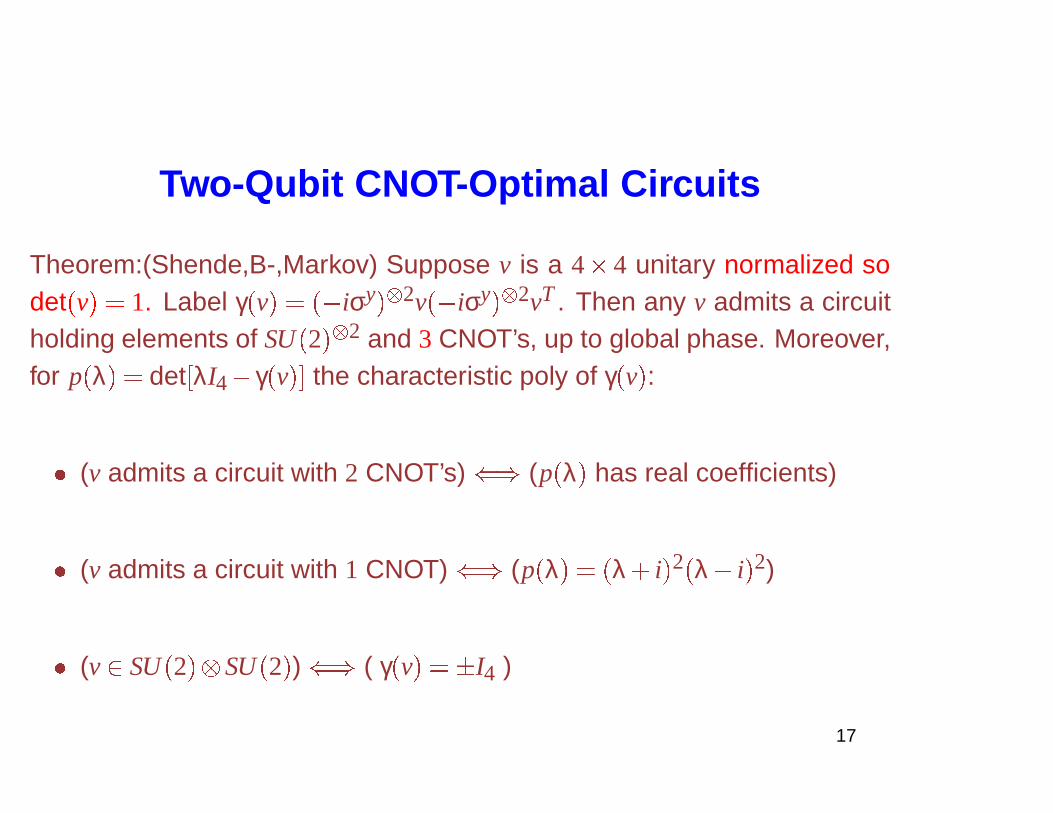
Two-Qubit CNOT-Optimal Circuits
Theorem:(Shende,B-,Markov) Suppose v is a 4 � 4 unitary normalized sodet � v � � 1. Label γ � v � � �� iσy ��� 2v �� iσy ��� 2vT . Then any v admits a circuitholding elements of SU � 2 � � 2 and 3 CNOT’s, up to global phase. Moreover,for p � λ � � det � λI4� γ � v �� the characteristic poly of γ � v � :
� (v admits a circuit with 2 CNOT’s) � (p � λ � has real coefficients)
� (v admits a circuit with 1 CNOT) � (p � λ � � � λ� i � 2 � λ� i � 2)
� (v� SU � 2 � SU � 2 � ) � ( γ � v � � � I4 )
17
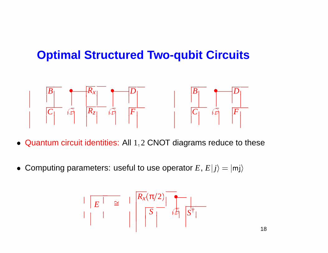
Optimal Structured Two-qubit Circuits
B � Rx � D B � D
C 76540123 Rz 76540123 F C 76540123 F
� Quantum circuit identities: All 1� 2 CNOT diagrams reduce to these
� Computing parameters: useful to use operator E, E � j � � ��� � �
ERx � π � 2 � �
��
S 76540123 S†
18
Outline
I. Introduction to Quantum CircuitsII. Two Qubit Circuits (CD)
III. Circuits for Diagonal UnitariesIV. Half CNOT per Entry (CSD)V. Differntial Topology & Lower Bounds
19
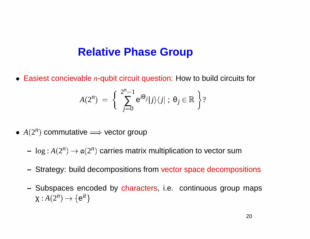
Relative Phase Group
� Easiest concievable n-qubit circuit question: How to build circuits for
A � 2n � �
2n � 1
∑j� 0
eiθ j � j � � j � ; θ j� � ?
� A � 2n � commutative � � vector group
– log : A � 2n � � � � 2n � carries matrix multiplication to vector sum
– Strategy: build decompositions from vector space decompositions
– Subspaces encoded by characters, i.e. continuous group mapsχ : A � 2n � � � eit
�
20
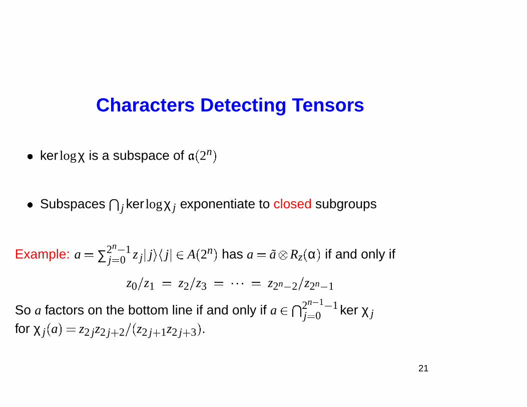
Characters Detecting Tensors
� ker logχ is a subspace of � � 2n �
� Subspaces � j ker logχ j exponentiate to closed subgroups
Example: a � ∑2n � 1j� 0 z j � j � � j �� A � 2n � has a � a Rz � α � if and only if
z0 � z1 � z2 � z3 � � � � � z2n � 2 � z2n � 1
So a factors on the bottom line if and only if a� �
2n� 1 � 1j� 0 ker χ j
for χ j � a � � z2 jz2 j � 2 � � z2 j � 1z2 j � 3 � .
21
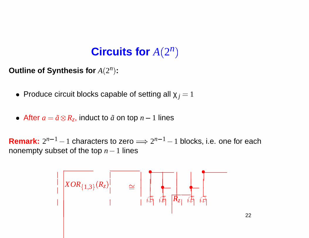
Circuits for A
�
2n
�
Outline of Synthesis for A � 2n � :
� Produce circuit blocks capable of setting all χ j � 1
� After a � a Rz, induct to a on top n� 1 lines
Remark: 2n � 1� 1 characters to zero � � 2n � 1� 1 blocks, i.e. one for eachnonempty subset of the top n� 1 lines
XOR
�
1 � 3 �
� Rz �
� �
�� � �
76540123 76540123 Rz 76540123 76540123
22
Circuits for A
�
2n
�
, Cont.
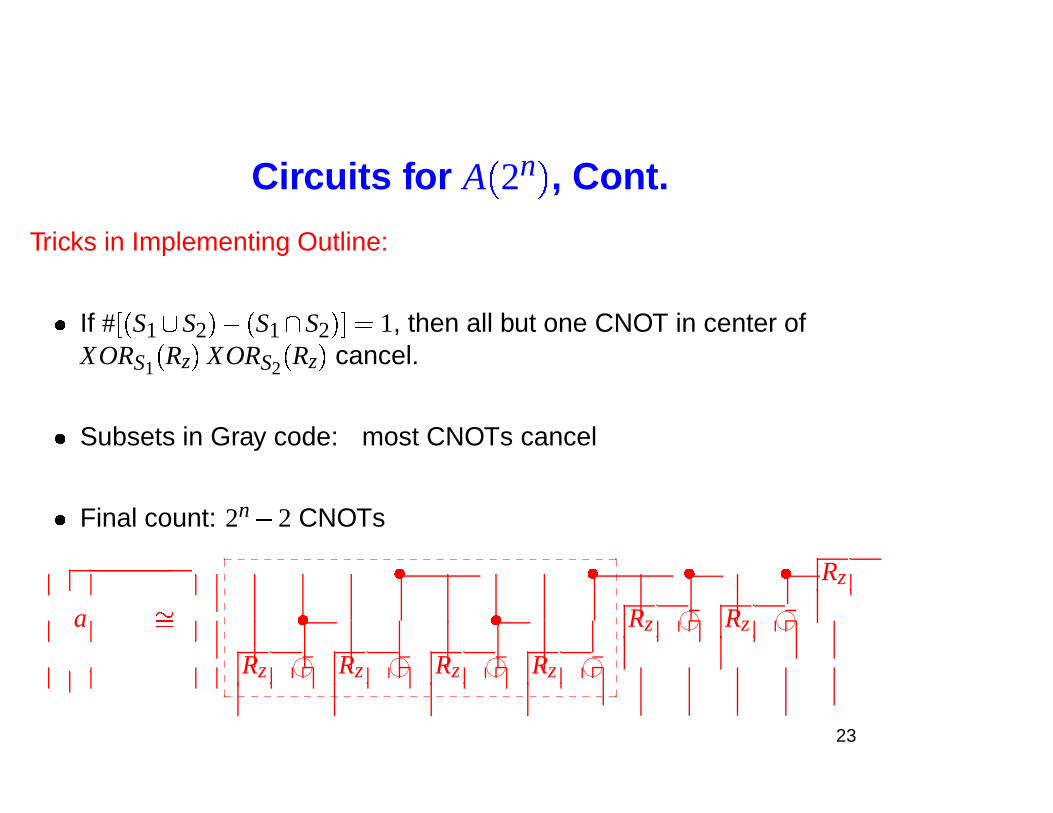
Tricks in Implementing Outline:
� If # � � S1 � S2 ��� � S1� S2 �� � 1, then all but one CNOT in center ofXORS1 � Rz � XORS2 � Rz � cancel.
� Subsets in Gray code: most CNOTs cancel
� Final count: 2n� 2 CNOTs
a
� � � � Rz
�� � � Rz 76540123 Rz 76540123
Rz 76540123 Rz 76540123 Rz 76540123 Rz 76540123
_ _ _ _ _ _ _ _ _ _ _ _ _ _ _ _ _ _ _ _ _ _ _ _ _ _ _ _ _ _�
�
�
�
�
�
�
�
�
�
�
�
�
�
�
�
�
�
�
�
_ _ _ _ _ _ _ _ _ _ _ _ _ _ _ _ _ _ _ _ _ _ _ _ _ _ _ _ _ _
23
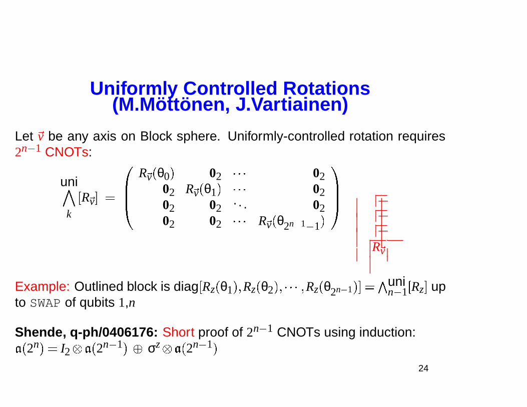
Uniformly Controlled Rotations(M.Mottonen, J.Vartiainen)
Let �v be any axis on Block sphere. Uniformly-controlled rotation requires2n � 1 CNOTs:
uni
k
�R �v� � ��
R �v � θ0 � 02 � � � 0202 R �v � θ1 � � � � 0202 02
. . . 0202 02 � � � R �v � θ2n� 1 � 1 �
��
R �v
Example: Outlined block is diag �Rz � θ1 � � Rz � θ2 �� � � � � Rz � θ2n� 1 �� � �
unin � 1 �Rz� up
to SWAP of qubits 1,n
Shende, q-ph/0406176: Short proof of 2n � 1 CNOTs using induction:
� � 2n � � I2 � � 2n � 1 � � σz � � 2n � 1 �
24
Outline
I. Introduction to Quantum CircuitsII. Two Qubit Circuits (CD)
III. Circuits for Diagonal UnitariesIV. Half CNOT per Entry (CSD)V. Differntial Topology & Lower Bounds
25
Universal Circuits
Goal: Build a universal quantum circuit for u be 2n
� 2n unitary evolution
� Change rotation angles: any u up to phase
� Preview: At least 4n� 1 rotation boxes R �v, at least 14 � 4n� 3n� 1 � CNOTs
� Prior art
– Barenco Bennett Cleve DiVincenzo Margolus Shor Sleator J.SmolinWeinfurter (1995) � 50n2
� 4n CNOTs
– Vartiainen, Mottonen, Bergholm, Salomaa, � 8 � 4n (2003),
� 4n (2004)
26
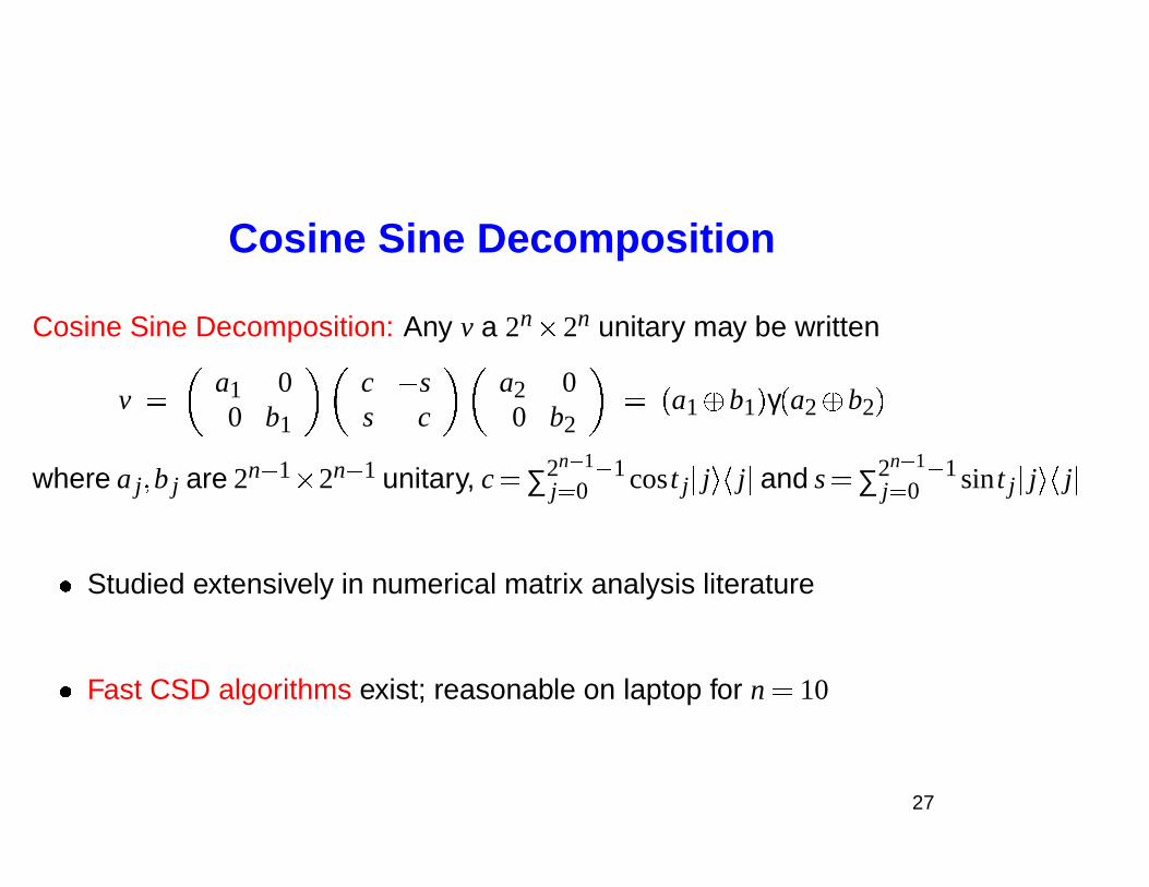
Cosine Sine Decomposition
Cosine Sine Decomposition: Any v a 2n
� 2n unitary may be written
v �
a1 00 b1
c � ss c
a2 00 b2
� � a1� b1 � γ � a2� b2 �
where a j� b j are 2n � 1
� 2n � 1 unitary, c � ∑2n� 1 � 1j� 0 cos t j � j � � j � and s � ∑2n� 1 � 1
j� 0 sin t j � j � � j �
� Studied extensively in numerical matrix analysis literature
� Fast CSD algorithms exist; reasonable on laptop for n � 10
27
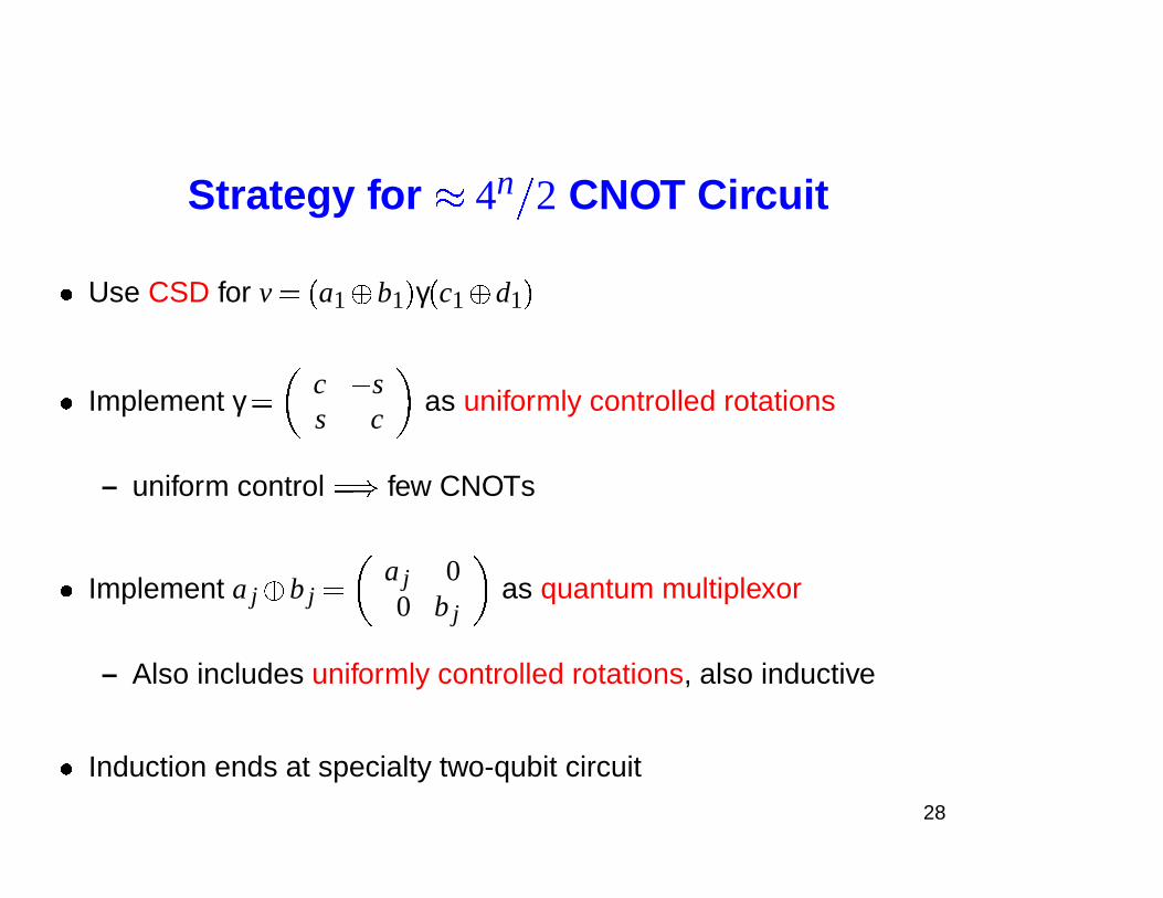
Strategy for � 4n
� 2 CNOT Circuit
� Use CSD for v � � a1� b1 � γ � c1� d1 �
� Implement γ �
c � ss c
as uniformly controlled rotations
– uniform control � � few CNOTs
� Implement a j� b j �
a j 00 b j
as quantum multiplexor
– Also includes uniformly controlled rotations, also inductive
� Induction ends at specialty two-qubit circuit
28
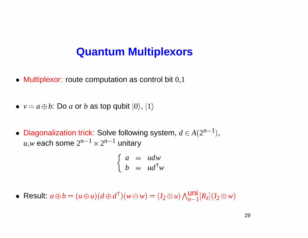
Quantum Multiplexors
� Multiplexor: route computation as control bit 0,1
� v � a� b: Do a or b as top qubit � 0 � , � 1 �
� Diagonalization trick: Solve following system, d� A � 2n � 1 � ,u,w each some 2n � 1
� 2n � 1 unitary
a � udwb � ud†w
� Result: a� b � � u� u � � d� d† � � w� w � � � I2 u � �
unin � 1 �Rz� � I2 w �
29
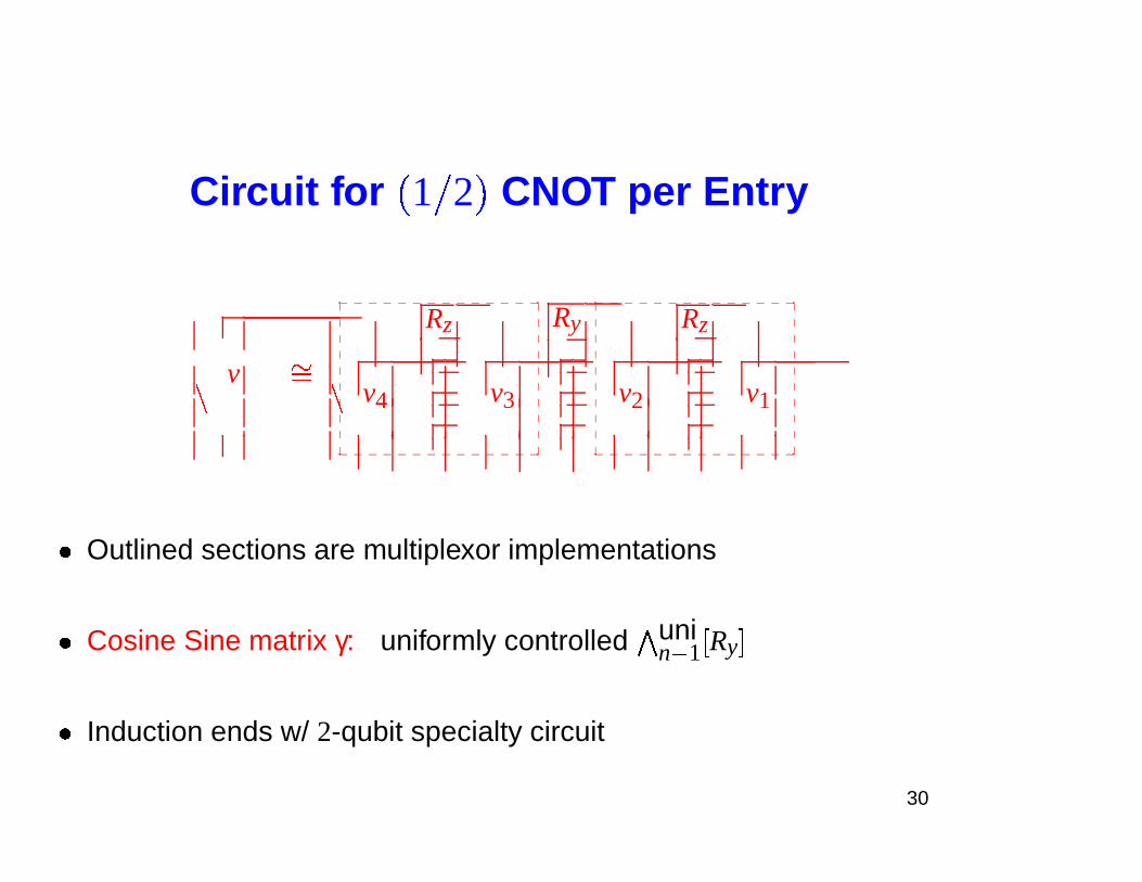
Circuit for
�
1 � 2
�
CNOT per Entry
v
Rz Ry Rz
v4 v3 v2 v1�
��
�
_ _ _ _ _ _ _ _ _ _ _ _ _ _�
�
�
�
�
�
�
�
�
�
�
�
�
�
�
�
�
�
�
�
_ _ _ _ _ _ _ _ _ _ _ _ _ _
_ _ _ _ _ _ _ _ _ _ _ _ _ _�
�
�
�
�
�
�
�
�
�
�
�
�
�
�
�
�
�
�
�
_ _ _ _ _ _ _ _ _ _ _ _ _ _
� Outlined sections are multiplexor implementations
� Cosine Sine matrix γ: uniformly controlled �unin � 1 �Ry�
� Induction ends w/ 2-qubit specialty circuit
30
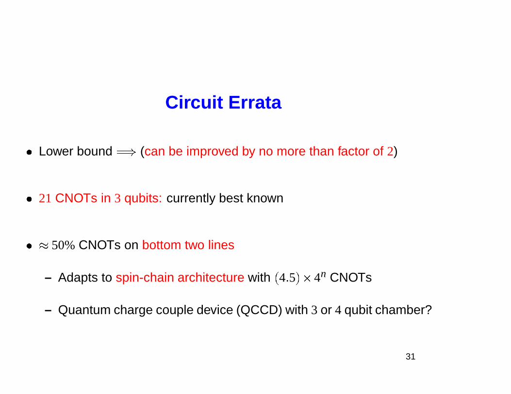
Circuit Errata
� Lower bound � � (can be improved by no more than factor of 2)
� 21 CNOTs in 3 qubits: currently best known
� � 50% CNOTs on bottom two lines
– Adapts to spin-chain architecture with � 4� 5 � � 4n CNOTs
– Quantum charge couple device (QCCD) with 3 or 4 qubit chamber?
31
Outline
I. Introduction to Quantum CircuitsII. Two Qubit Circuits (CD)
III. Circuits for Diagonal UnitariesIV. Half CNOT per Entry (CSD)V. Differntial Topology & Lower Bounds
32
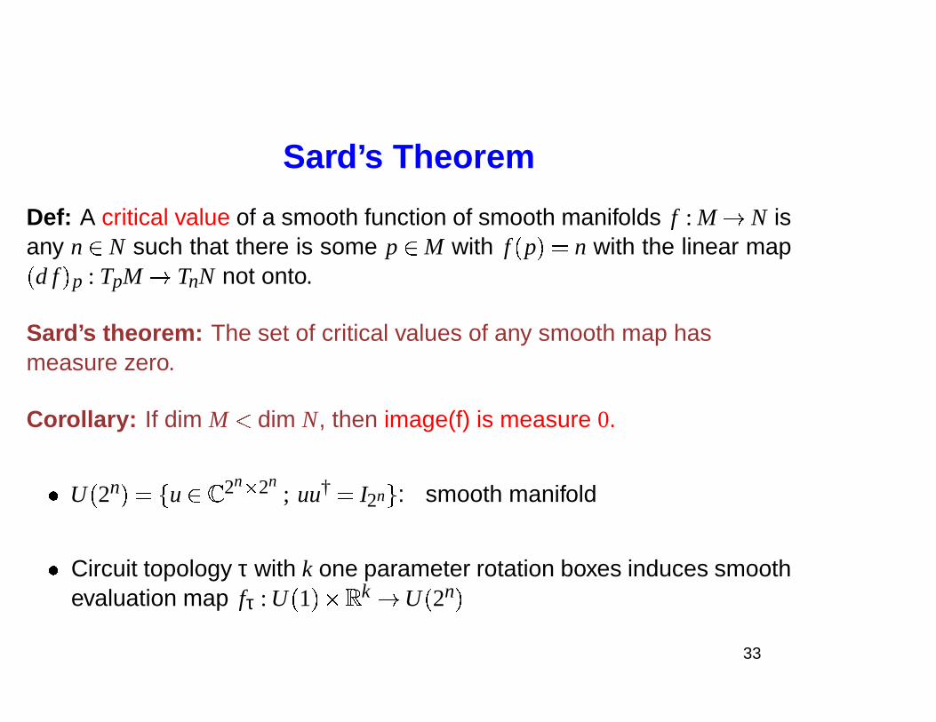
Sard’s Theorem
Def: A critical value of a smooth function of smooth manifolds f : M � N isany n� N such that there is some p� M with f � p � � n with the linear map
� d f � p : TpM � TnN not onto.
Sard’s theorem: The set of critical values of any smooth map hasmeasure zero.
Corollary: If dim M � dim N, then image(f) is measure 0.
� U � 2n � �
� u� � 2n � 2n; uu† � I2n � : smooth manifold
� Circuit topology τ with k one parameter rotation boxes induces smoothevaluation map fτ : U � 1 � � �
k � U � 2n �
33
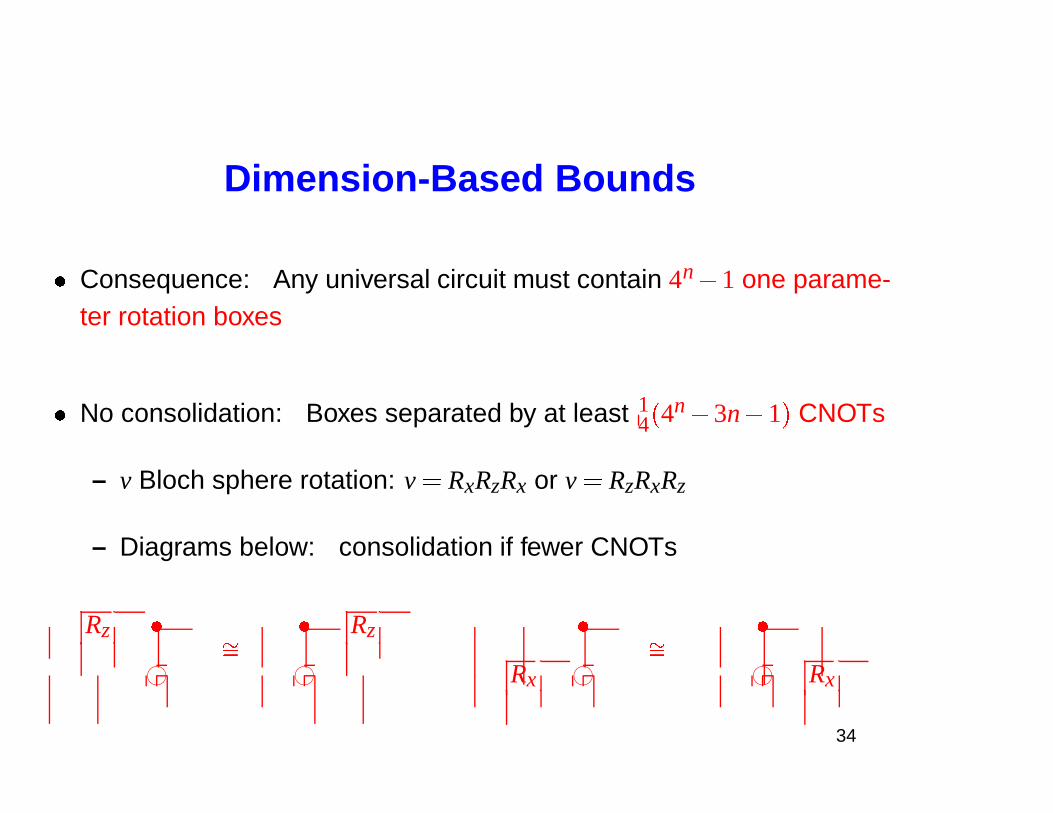
Dimension-Based Bounds
� Consequence: Any universal circuit must contain 4n� 1 one parame-ter rotation boxes
� No consolidation: Boxes separated by at least 14 � 4n� 3n� 1 � CNOTs
– v Bloch sphere rotation: v � RxRzRx or v � RzRxRz
– Diagrams below: consolidation if fewer CNOTs
Rz � � Rz � �
76540123
��
76540123 Rx 76540123
��76540123 Rx
34
On-going Work
� Subgroups H of unitary group U � 2n �
– More structure, smaller circuits?
– Symmetries encoded within subgroups H
– Native gate libraries?
� Special purpose circuits
– Backwards: quantum circuits for doing numerical linear algebra?
– Entanglement dynamics and circuit structure
35
http://www.arxiv.org Coordinates
� Two-qubits: q-ph/0308045
� Diagonal circuits: q-ph/0303039
� Uniform control: q-ph/0404089
� � 1 � 2 � CNOT/entry: q-ph/0406176
� Circuit diagrams by Qcircuit.tex: q-ph/0406003
36
Recommended