════════════════════════════════════════════════
1
TouchScreen Controller
Installation Guide
VERSION : 2.5
DATE : 2005.12.09
════════════════════════════════════════════════
2
Table of Content
Chapter 1. TOUCH SCREEN CONTROLLER………………………………………….. 3
About this Document………………………………………………………………………………… 3
Touch Screen Controller Components…………………………………………………………….. 3
Hardware System Requirements…………………………………………………………………… 3
Chapter 2.CONTROLLER FEATURES…………………………………………………... 4
Serial Controller Features…………………………………………………………………………… 4
PS/2 Controller Features……………………………………………………………………………. 5
USB Controller Features……………………………………………………………………………. 6
Chapter 3. TOUCH SCREEN CONTROLLER HARDWARE INSTALLATION... 7
5 Wires Resistive USB Touch Screen Controller Hardware Installation………………………. 7
5 Wires Resistive Serial Touch Screen Controller Hardware Installation………………………. 9
5 Wires Resistive PS/2 Touch Screen Controller Hardware Installation……………………….. 11
4 Wires Resistive Serial Touch Screen Controller Hardware Installation………………………. 13
4 Wires Resistive PS/2 Touch Screen Controller Hardware Installation……………………….. 15
Chapter 4. SOFTWARE INSTALLATION………………………………………………… 17
Chapter 5. DRIVER INSTALLATION………………………………………………………. 19Windows XP………………………………………………………………………………………….. 19Windows XP Embedded…………………………………………………………………………….. 19Windows 2000.……………………………………………………………………………………….. 20Windows Server 2003……………………………………………………………………………….. 20Windows NT 4.0.……………………………………………………………………………………... 21Windows ME.…………………………………………………………………………………………. 21Windows 98.………………………………………………………………………………………….. 22Windows 95.………………………………………………………………………………………….. 22Windows CE.…………………………………………………………………………………………. 22Windows 3.1………………………………………………………………………………………….. 23MS-DOS.……………………………………………………………………………………………… 23Linux…..………………………………………………………………………………………………. 24
Chapter 6. UNINSTALL TOUCH SCREEN DRIVER…………………………….. 31
Chapter 7. TOUCH SCREEN DRIVER FUNCTION……………………………… 31
════════════════════════════════════════════════
3
Chapter 1. TOUCH SCREEN CONTROLLER About this Document The information in this document is subject to change without notice. Touch Screen Controller Components • Enhanced anti-noise SMD multi-layered controller board with 2 attached cables • Serial controller with a keyboard power tap cable • CD-ROM Drive Diskette Hardware System Requirements • Computer: IBM Pentium Compatible or above • Hard Disk Drive: 5MB of free memory • Drive: CD-ROM drive • LCD or Monitor: SVGA color • Video card: VESA Super VGA BIOS Ext. version 1.2 or newer SVGA • Keyboard port: Output 4~6VDC (max. use<35ma) • Connect port: RS-232 port or PS/2 port or USB port • Mouse: Low power consumption model (2 buttons)
════════════════════════════════════════════════
4
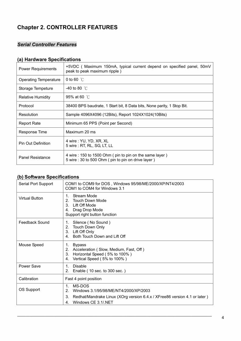
Chapter 2. CONTROLLER FEATURES Serial Controller Features (a) Hardware Specifications
Power Requirements +5VDC ( Maximum 150mA, typical current depend on specified panel, 50mV peak to peak maximum ripple )
Operating Temperature 0 to 60 ℃
Storage Tempeture -40 to 80 ℃
Relative Humidity 95% at 60 ℃
Protocol 38400 BPS baudrate, 1 Start bit, 8 Data bits, None parity, 1 Stop Bit.
Resolution Sample 4096X4096 (12Bits), Report 1024X1024(10Bits)
Report Rate Minimum 65 PPS (Point per Second)
Response Time Maximum 20 ms
Pin Out Definition 4 wire : YU, YD, XR, XL 5 wire : RT, RL, SG, LT, LL
Panel Resistance 4 wire : 150 to 1500 Ohm ( pin to pin on the same layer ) 5 wire : 30 to 500 Ohm ( pin to pin on drive layer )
(b) Software Specifications Serial Port Support
COM1 to COM9 for DOS , Windows 95/98/ME/2000/XP/NT4/2003 COM1 to COM4 for Windows 3.1
Virtual Button
1. Stream Mode 2. Touch Down Mode 3. Lift Off Mode 4. Drag Drop Mode Support right button function
Feedback Sound
1. Silence ( No Sound ) 2. Touch Down Only 3. Lift Off Only 4. Both Touch Down and Lift Off
Mouse Speed
1. Bypass 2. Acceleration ( Slow, Medium, Fast, Off ) 3. Horizontal Speed ( 5% to 100% ) 4. Vertical Speed ( 5% to 100% )
Power Save
1. Disable 2. Enable ( 10 sec. to 300 sec. )
Calibration Fast 4 point position
OS Support
1. MS-DOS 2. Windows 3.1/95/98/ME/NT4/2000/XP/2003 3. Redhat/Mandrake Linux (XOrg version 6.4.x / XFree86 version 4.1 or later ) 4. Windows CE 3.1/.NET
════════════════════════════════════════════════
5
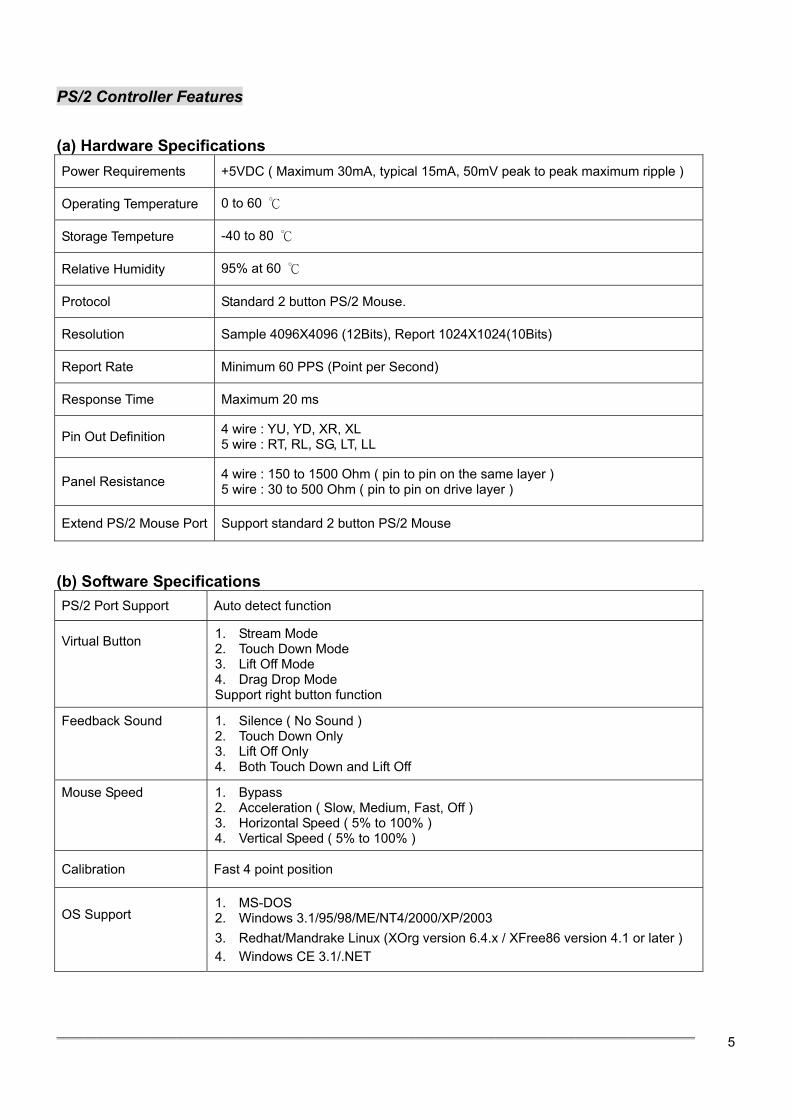
PS/2 Controller Features (a) Hardware Specifications
Power Requirements +5VDC ( Maximum 30mA, typical 15mA, 50mV peak to peak maximum ripple )
Operating Temperature 0 to 60 ℃
Storage Tempeture -40 to 80 ℃
Relative Humidity 95% at 60 ℃
Protocol Standard 2 button PS/2 Mouse.
Resolution Sample 4096X4096 (12Bits), Report 1024X1024(10Bits)
Report Rate Minimum 60 PPS (Point per Second)
Response Time Maximum 20 ms
Pin Out Definition 4 wire : YU, YD, XR, XL 5 wire : RT, RL, SG, LT, LL
Panel Resistance 4 wire : 150 to 1500 Ohm ( pin to pin on the same layer ) 5 wire : 30 to 500 Ohm ( pin to pin on drive layer )
Extend PS/2 Mouse Port Support standard 2 button PS/2 Mouse
(b) Software Specifications
PS/2 Port Support Auto detect function
Virtual Button
1. Stream Mode 2. Touch Down Mode 3. Lift Off Mode 4. Drag Drop Mode Support right button function
Feedback Sound
1. Silence ( No Sound ) 2. Touch Down Only 3. Lift Off Only 4. Both Touch Down and Lift Off
Mouse Speed
1. Bypass 2. Acceleration ( Slow, Medium, Fast, Off ) 3. Horizontal Speed ( 5% to 100% ) 4. Vertical Speed ( 5% to 100% )
Calibration Fast 4 point position
OS Support
1. MS-DOS 2. Windows 3.1/95/98/ME/NT4/2000/XP/2003 3. Redhat/Mandrake Linux (XOrg version 6.4.x / XFree86 version 4.1 or later ) 4. Windows CE 3.1/.NET
════════════════════════════════════════════════
6
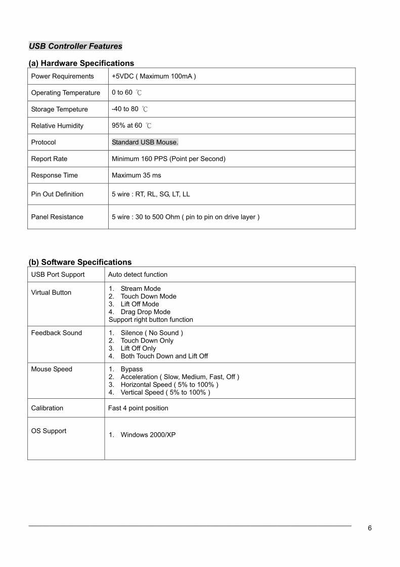
USB Controller Features (a) Hardware Specifications Power Requirements +5VDC ( Maximum 100mA )
Operating Temperature 0 to 60 ℃
Storage Tempeture -40 to 80 ℃
Relative Humidity 95% at 60 ℃
Protocol Standard USB Mouse.
Report Rate Minimum 160 PPS (Point per Second)
Response Time Maximum 35 ms
Pin Out Definition 5 wire : RT, RL, SG, LT, LL
Panel Resistance 5 wire : 30 to 500 Ohm ( pin to pin on drive layer )
(b) Software Specifications USB Port Support Auto detect function
Virtual Button
1. Stream Mode 2. Touch Down Mode 3. Lift Off Mode 4. Drag Drop Mode Support right button function
Feedback Sound
1. Silence ( No Sound ) 2. Touch Down Only 3. Lift Off Only 4. Both Touch Down and Lift Off
Mouse Speed
1. Bypass 2. Acceleration ( Slow, Medium, Fast, Off ) 3. Horizontal Speed ( 5% to 100% ) 4. Vertical Speed ( 5% to 100% )
Calibration Fast 4 point position
OS Support
1. Windows 2000/XP
════════════════════════════════════════════════
7
Chapter 3. TOUCH SCREEN CONTROLLER HARDWARE INSTALLATION 5 Wires Resistive USB Touch Screen Controller Hardware Installation This chapter discusses how to install your 5 wires resistive serial touch screen controller, follow the directions starting on the next section to install the controller to your computer.
IMPORTANT: Before connecting the touch screen controller to your computer system,Be sure that the computer system is turned off.
1. Turning Off Your Computer System
Before you install the 5 wires resistive USB touch screen controller, turn off your computer system. 2. Connecting the Controller
The 5 wires resistive USB touch screen controller included a USB cable, which has 5-pin D connector.. Plug the USB cable into a USB port on your computer directly .
3. Supplying Power to the Controller
The 5 wires resistive USB touch screen controller included a 5-pin USB cable, which using to provide power to the controller. To connect USB cable: • Plug the USB cable into usb port.
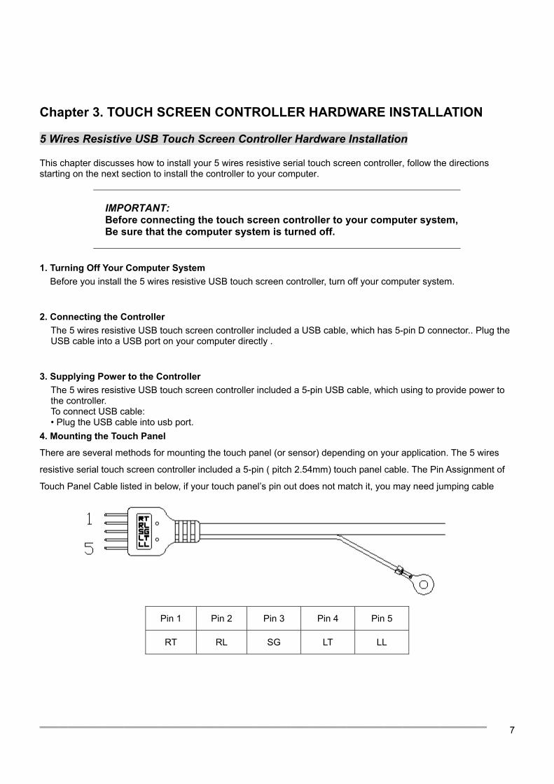
4. Mounting the Touch Panel
There are several methods for mounting the touch panel (or sensor) depending on your application. The 5 wires
resistive serial touch screen controller included a 5-pin ( pitch 2.54mm) touch panel cable. The Pin Assignment of
Touch Panel Cable listed in below, if your touch panel’s pin out does not match it, you may need jumping cable
Pin 1 Pin 2 Pin 3 Pin 4 Pin 5
RT RL SG LT LL
════════════════════════════════════════════════
8
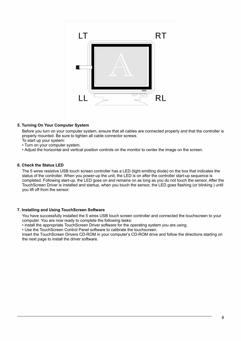
5. Turning On Your Computer System
Before you turn on your computer system, ensure that all cables are connected properly and that the controller is properly mounted. Be sure to tighten all cable connector screws. To start up your system: • Turn on your computer system. • Adjust the horizontal and vertical position controls on the monitor to center the image on the screen.
6. Check the Status LED
The 5 wires resistive USB touch screen controller has a LED (light emitting diode) on the box that indicates the status of the controller. When you power-up the unit, the LED is on after the controller start-up sequence is completed. Following start-up, the LED goes on and remains on as long as you do not touch the sensor. After the TouchScreen Driver is installed and startup, when you touch the sensor, the LED goes flashing (or blinking ) until you lift off from the sensor.
7. Installing and Using TouchScreen Software You have successfully installed the 5 wires USB touch screen controller and connected the touchscreen to your computer. You are now ready to complete the following tasks: • install the appropriate TouchScreen Driver software for the operating system you are using. • Use the TouchScreen Control Panel software to calibrate the touchscreen. Insert the TouchScreen Drivers CD-ROM in your computer’s CD-ROM drive and follow the directions starting on the next page to install the driver software.
════════════════════════════════════════════════
9
5 Wires Resistive Serial Touch Screen Controller Hardware Installation This chapter discusses how to install your 5 wires resistive serial touch screen controller, follow the directions starting on the next section to install the controller to your computer.
IMPORTANT: Before connecting the touch screen controller to your computer system,Be sure that the computer system is turned off.
1. Turning Off Your Computer System
Before you install the 5 wires resistive serial touch screen controller, turn off your computer system. 2. Connecting the Controller
The 5 wires resistive serial touch screen controller included a RS-232 cable, which has 9-pin D connector. You may need 9-pin to 25-pin adapter if the only available COM port on your computer has 25 pins. Plug the RS-232 cable into a COM port on your computer, directly or through the adapter.
3. Supplying Power to the Controller
The 5 wires resistive serial touch screen controller included a 6-pin IBM PS/2 compatible keyboard power tap cable, which using to provide power to the controller. You may need 5-pin to 6-pin IBM PS/2 compatible keyboard adapter if the only available keyboard socket on your computer has 5-pin. To connect the keyboard power tap cable: • Disconnect the keyboard cable from the back of your computer. • Plug the keyboard cable into the power tap cable. • Plug the power tap cable into the keyboard socket on the back of your computer. • Connect the DC plug from the power tap cable to the jack built into the 9-pin D connector.
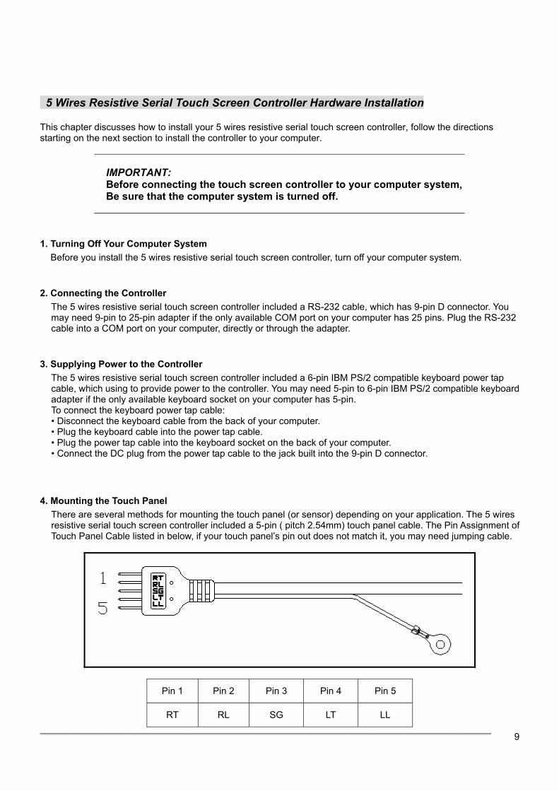
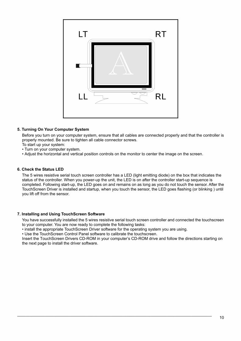
4. Mounting the Touch Panel There are several methods for mounting the touch panel (or sensor) depending on your application. The 5 wires resistive serial touch screen controller included a 5-pin ( pitch 2.54mm) touch panel cable. The Pin Assignment of Touch Panel Cable listed in below, if your touch panel’s pin out does not match it, you may need jumping cable.
Pin 1 Pin 2 Pin 3 Pin 4 Pin 5
RT RL SG LT LL
════════════════════════════════════════════════
10
5. Turning On Your Computer System Before you turn on your computer system, ensure that all cables are connected properly and that the controller is properly mounted. Be sure to tighten all cable connector screws. To start up your system: • Turn on your computer system. • Adjust the horizontal and vertical position controls on the monitor to center the image on the screen.
6. Check the Status LED
The 5 wires resistive serial touch screen controller has a LED (light emitting diode) on the box that indicates the status of the controller. When you power-up the unit, the LED is on after the controller start-up sequence is completed. Following start-up, the LED goes on and remains on as long as you do not touch the sensor. After the TouchScreen Driver is installed and startup, when you touch the sensor, the LED goes flashing (or blinking ) until you lift off from the sensor.
7. Installing and Using TouchScreen Software You have successfully installed the 5 wires resistive serial touch screen controller and connected the touchscreen to your computer. You are now ready to complete the following tasks: • install the appropriate TouchScreen Driver software for the operating system you are using. • Use the TouchScreen Control Panel software to calibrate the touchscreen. Insert the TouchScreen Drivers CD-ROM in your computer’s CD-ROM drive and follow the directions starting on the next page to install the driver software.
════════════════════════════════════════════════
11
5 Wires Resistive PS/2 Touch Screen Controller Hardware Installation
This chapter discusses how to install your 5 wires resistive PS/2 touch screen controller, follow the directions starting on the next section to install the controller to your computer.
IMPORTANT: Before connecting the touch screen controller to your computer system,Be sure that the computer system is turned off.
1. Turning Off Your Computer System
Before you install the 5 wires resistive PS/2 touch screen controller, turn off your computer system. 2. Connecting the Controller
The 5 wire resistive PS/2 touch screen controller included a Y-type cable, which has a 6-pin Male Mini Din connecter and a 6-pin Female Mini Din connecter. You may use the Y-type cable to connect the controller to your computer and connect the PS/2 mouse to the controller.
3. Supplying Power to the Controller
To connect the controller: • Disconnect the PS/2 mouse cable from the back of your computer. • Plug the PS/2 mouse cable into the Y-type cable. • Plug the Y-type cable into the mouse socket on the back of your computer.
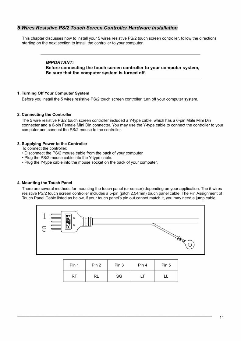
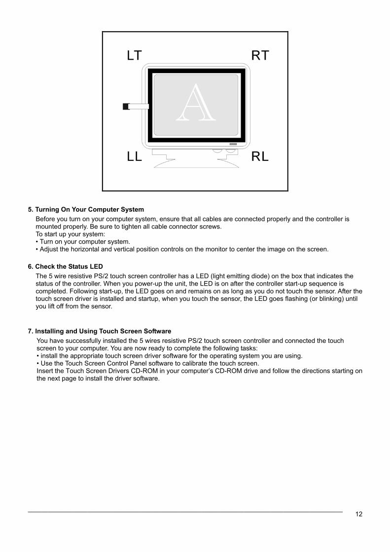
4. Mounting the Touch Panel There are several methods for mounting the touch panel (or sensor) depending on your application. The 5 wires resistive PS/2 touch screen controller includes a 5-pin (pitch 2.54mm) touch panel cable. The Pin Assignment of Touch Panel Cable listed as below, if your touch panel’s pin out cannot match it, you may need a jump cable.
Pin 1 Pin 2 Pin 3 Pin 4 Pin 5
RT RL SG LT LL
════════════════════════════════════════════════
12
5. Turning On Your Computer System Before you turn on your computer system, ensure that all cables are connected properly and the controller is mounted properly. Be sure to tighten all cable connector screws. To start up your system: • Turn on your computer system. • Adjust the horizontal and vertical position controls on the monitor to center the image on the screen.
6. Check the Status LED
The 5 wire resistive PS/2 touch screen controller has a LED (light emitting diode) on the box that indicates the status of the controller. When you power-up the unit, the LED is on after the controller start-up sequence is completed. Following start-up, the LED goes on and remains on as long as you do not touch the sensor. After the touch screen driver is installed and startup, when you touch the sensor, the LED goes flashing (or blinking) until you lift off from the sensor.
7. Installing and Using Touch Screen Software
You have successfully installed the 5 wires resistive PS/2 touch screen controller and connected the touch screen to your computer. You are now ready to complete the following tasks: • install the appropriate touch screen driver software for the operating system you are using. • Use the Touch Screen Control Panel software to calibrate the touch screen. Insert the Touch Screen Drivers CD-ROM in your computer’s CD-ROM drive and follow the directions starting on the next page to install the driver software.

════════════════════════════════════════════════
13
4 Wires Resistive Serial Touch Screen Controller Hardware Installation
This chapter discusses how to install your 4 wires resistive serial touch screen controller, follow the directions starting on the next section to install the controller to your computer.
IMPORTANT: Before connecting the touch screen controller to your computer system,Be sure that the computer system is turned off.
1. Turning Off Your Computer System
Before you install the 4 wires resistive serial touch screen controller, turn off your computer system. 2. Connecting the Controller
The 4 wires resistive serial touch screen controller includes a 6-pin IBM PS/2 compatible keyboard power tap cable, which using to provide power to the controller. You may need 5-pin to 6-pin IBM PS/2 compatible keyboard adapter if the only available keyboard socket on your computer has 5-pin. To connect the keyboard power tap cable: • Disconnect the keyboard cable from the back of your computer. • Plug the keyboard cable into the power tap cable. • Plug the power tap cable into the keyboard socket on the back of your computer. • Connect the DC plug from the power tap cable to the jack built into the 9-pin D connector.
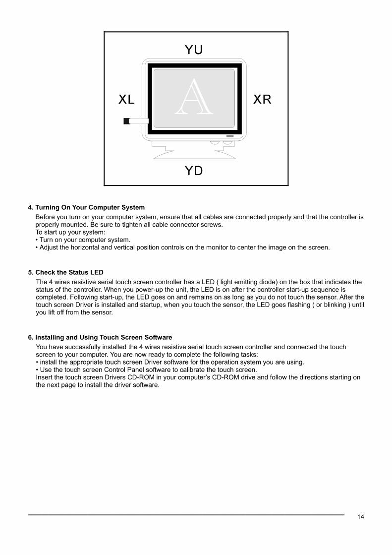
3. Mounting the Touch Panel There are several methods for mounting the touch panel (or sensor) depending on your application. The 4 wires resistive serial touch screen controller included a 4-pin ( pitch 2.54mm) touch panel cable. The Pin Assignment of Touch Panel Cable listed in below, if your touch panel’s pin out does not match it, you may need jumping cable.
Pin 1 Pin 2 Pin 3 Pin 4
YU YD XR XL
════════════════════════════════════════════════
14
4. Turning On Your Computer System
Before you turn on your computer system, ensure that all cables are connected properly and that the controller is properly mounted. Be sure to tighten all cable connector screws. To start up your system: • Turn on your computer system. • Adjust the horizontal and vertical position controls on the monitor to center the image on the screen.
5. Check the Status LED
The 4 wires resistive serial touch screen controller has a LED ( light emitting diode) on the box that indicates the status of the controller. When you power-up the unit, the LED is on after the controller start-up sequence is completed. Following start-up, the LED goes on and remains on as long as you do not touch the sensor. After the touch screen Driver is installed and startup, when you touch the sensor, the LED goes flashing ( or blinking ) until you lift off from the sensor.
6. Installing and Using Touch Screen Software
You have successfully installed the 4 wires resistive serial touch screen controller and connected the touch screen to your computer. You are now ready to complete the following tasks: • install the appropriate touch screen Driver software for the operation system you are using. • Use the touch screen Control Panel software to calibrate the touch screen. Insert the touch screen Drivers CD-ROM in your computer’s CD-ROM drive and follow the directions starting on the next page to install the driver software.
════════════════════════════════════════════════
15
4 Wires Resistive PS/2 Touch Screen Controller Hardware Installation
This chapter discusses how to install your 4 wires resistive ps/2 touch screen controller, follow the directions starting on the next section to install the controller to your computer.
IMPORTANT: Before connecting the TouchScreen Controller to your computer system,Be sure that the computer system is turned off.
1. Turning Off Your Computer System
Before you install the 4 wire resistive PS/2 touch screen controller, turn off your computer system. 2. Connecting the Controller
The 4 wire resistive PS/2 touch screen controller included a Y-type cable, which has a 6-pin Male Mini Din connecter and a 6-pin Female Mini Din connecter. You may use the Y-type cable to connect the controller to your computer and connect the PS/2 mouse to the controller. To connect the controller: • Disconnect the PS/2 mouse cable from the back of your computer. • Plug the PS/2 mouse cable into the Y-type cable. • Plug the Y-type cable into the mouse socket on the back of your computer.
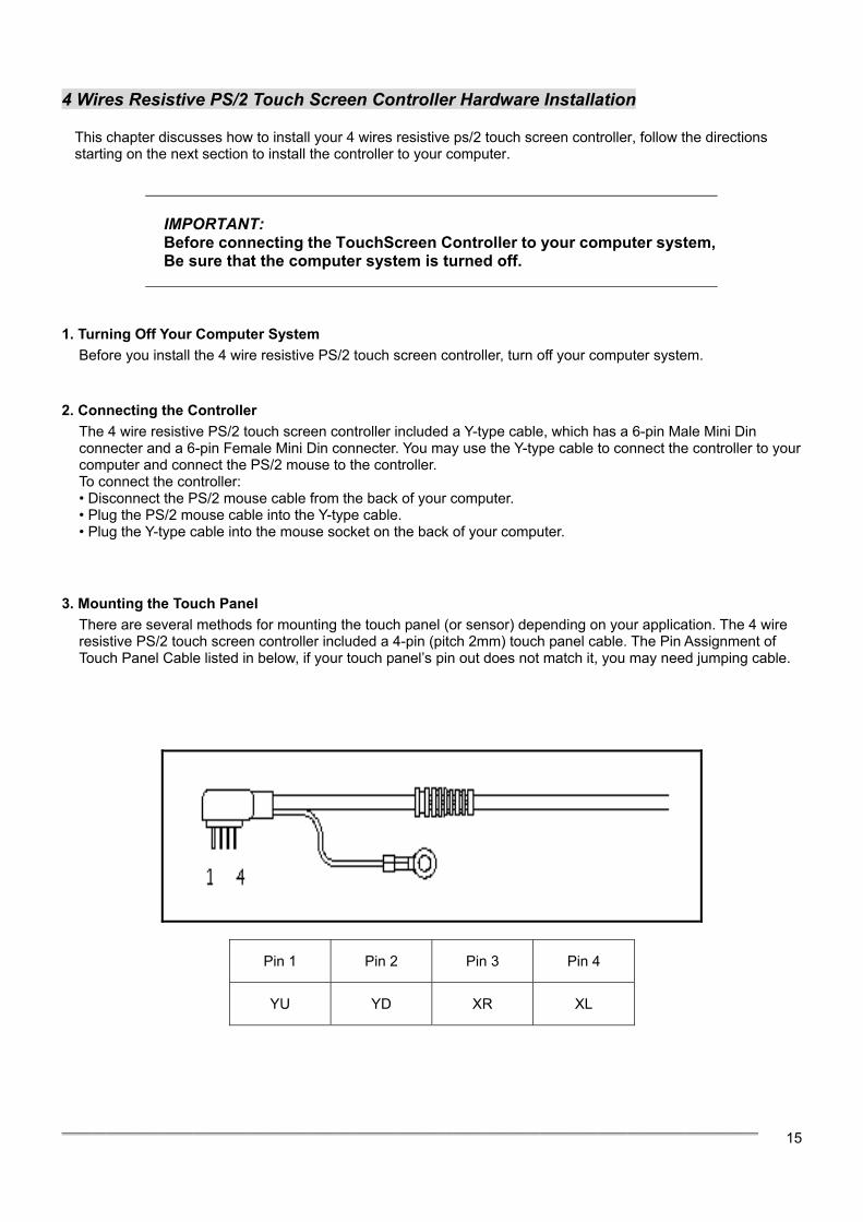
3. Mounting the Touch Panel
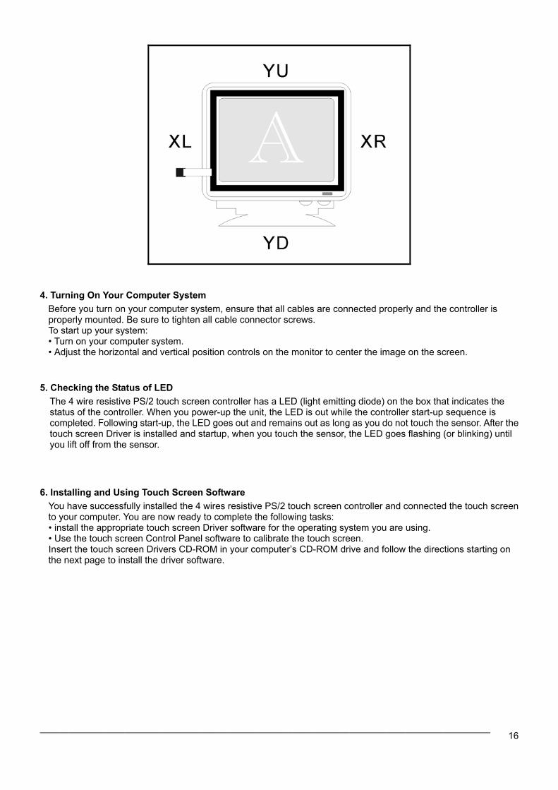
There are several methods for mounting the touch panel (or sensor) depending on your application. The 4 wire resistive PS/2 touch screen controller included a 4-pin (pitch 2mm) touch panel cable. The Pin Assignment of Touch Panel Cable listed in below, if your touch panel’s pin out does not match it, you may need jumping cable.
Pin 1 Pin 2 Pin 3 Pin 4
YU YD XR XL
════════════════════════════════════════════════
16
4. Turning On Your Computer System
Before you turn on your computer system, ensure that all cables are connected properly and the controller is properly mounted. Be sure to tighten all cable connector screws. To start up your system: • Turn on your computer system. • Adjust the horizontal and vertical position controls on the monitor to center the image on the screen.
5. Checking the Status of LED
The 4 wire resistive PS/2 touch screen controller has a LED (light emitting diode) on the box that indicates the status of the controller. When you power-up the unit, the LED is out while the controller start-up sequence is completed. Following start-up, the LED goes out and remains out as long as you do not touch the sensor. After the touch screen Driver is installed and startup, when you touch the sensor, the LED goes flashing (or blinking) until you lift off from the sensor.
6. Installing and Using Touch Screen Software You have successfully installed the 4 wires resistive PS/2 touch screen controller and connected the touch screen to your computer. You are now ready to complete the following tasks: • install the appropriate touch screen Driver software for the operating system you are using. • Use the touch screen Control Panel software to calibrate the touch screen. Insert the touch screen Drivers CD-ROM in your computer’s CD-ROM drive and follow the directions starting on the next page to install the driver software.
════════════════════════════════════════════════
17
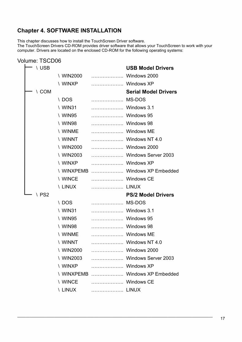
Chapter 4. SOFTWARE INSTALLATION This chapter discusses how to install the TouchScreen Driver software. The TouchScreen Drivers CD-ROM provides driver software that allows your TouchScreen to work with your computer. Drivers are located on the enclosed CD-ROM for the following operating systems: Volume: TSCD06 \ USB USB Model Drivers
\ WIN2000 ……………….. Windows 2000 \ WINXP ……………….. Windows XP \ COM Serial Model Drivers \ DOS ……………….. MS-DOS \ WIN31 ……………….. Windows 3.1 \ WIN95 ……………….. Windows 95 \ WIN98 ……………….. Windows 98 \ WINME ……………….. Windows ME \ WINNT ……………….. Windows NT 4.0 \ WIN2000 ……………….. Windows 2000 \ WIN2003 ……………….. Windows Server 2003 \ WINXP ……………….. Windows XP \ WINXPEMB ……………….. Windows XP Embedded \ WINCE ……………….. Windows CE \ LINUX ……………….. LINUX \ PS2 PS/2 Model Drivers
\ DOS ……………….. MS-DOS \ WIN31 ……………….. Windows 3.1 \ WIN95 ……………….. Windows 95 \ WIN98 ……………….. Windows 98 \ WINME ……………….. Windows ME \ WINNT ……………….. Windows NT 4.0 \ WIN2000 ……………….. Windows 2000 \ WIN2003 ……………….. Windows Server 2003 \ WINXP ……………….. Windows XP \ WINXPEMB ……………….. Windows XP Embedded \ WINCE ……………….. Windows CE \ LINUX ……………….. LINUX
════════════════════════════════════════════════
18
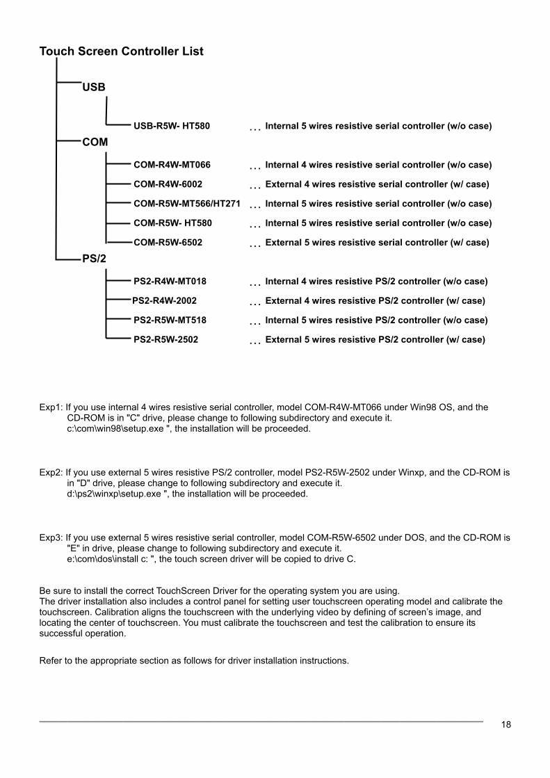
Touch Screen Controller List
USB
USB-R5W- HT580 … Internal 5 wires resistive serial controller (w/o case)
COM
COM-R4W-MT066 … Internal 4 wires resistive serial controller (w/o case)
COM-R4W-6002 … External 4 wires resistive serial controller (w/ case)
COM-R5W-MT566/HT271 … Internal 5 wires resistive serial controller (w/o case)
COM-R5W- HT580 … Internal 5 wires resistive serial controller (w/o case)
COM-R5W-6502 … External 5 wires resistive serial controller (w/ case)
PS/2
PS2-R4W-MT018 … Internal 4 wires resistive PS/2 controller (w/o case)
PS2-R4W-2002 … External 4 wires resistive PS/2 controller (w/ case)
PS2-R5W-MT518 … Internal 5 wires resistive PS/2 controller (w/o case)
PS2-R5W-2502 … External 5 wires resistive PS/2 controller (w/ case)
Exp1: If you use internal 4 wires resistive serial controller, model COM-R4W-MT066 under Win98 OS, and the
CD-ROM is in "C" drive, please change to following subdirectory and execute it. c:\com\win98\setup.exe ", the installation will be proceeded.
Exp2: If you use external 5 wires resistive PS/2 controller, model PS2-R5W-2502 under Winxp, and the CD-ROM is
in "D" drive, please change to following subdirectory and execute it. d:\ps2\winxp\setup.exe ", the installation will be proceeded.
Exp3: If you use external 5 wires resistive serial controller, model COM-R5W-6502 under DOS, and the CD-ROM is
"E" in drive, please change to following subdirectory and execute it. e:\com\dos\install c: ", the touch screen driver will be copied to drive C. Be sure to install the correct TouchScreen Driver for the operating system you are using. The driver installation also includes a control panel for setting user touchscreen operating model and calibrate the touchscreen. Calibration aligns the touchscreen with the underlying video by defining of screen’s image, and locating the center of touchscreen. You must calibrate the touchscreen and test the calibration to ensure its successful operation. Refer to the appropriate section as follows for driver installation instructions.
════════════════════════════════════════════════
19
Chapter 5. DRIVER INSTALLATION Windows XP This section discusses how to install the driver and calibrate the TouchScreen for Windows XP.
Note: You must have administrator access rights to install the driver.
To install the TouchScreen Driver:
• Inser the TouchScreen Drivers CD-ROM in your computer’s CD-ROM drive • Click Start > Run • Click the Browse button to locate the Setup.exe program on the path “\COM\WINXP” of the CD-ROM. • Click Open, then OK to run Setup.exe. • Follow the directions on the screen to complete the driver setup.
To calibrate the TouchScreen:
• Click Start > All Programs > TouchScreen V.x.x.COM > TouchScreen Control Panel V.x.x.COM ( where x.x is the Version of TouchScreen Driver ) • Click Calibration button to start calibrate. • Follow the directions on the screen to complete the calibration and test.
Windows XP Embedded This section discusses how to install the driver and calibrate the TouchScreen for Windows XP Embedded. There are two mothod to install the TSCOM driver for Windows XP Embedded: (1) To install the TSCOM driver after the Windows XP Embedded system startup, read "TSCOM_XPE_Setup.txt" file for detail information. Note: The TSCOM Driver for Windows XP also can be use for Windows XP Embedded in this mothod. (2) To build in the TSCOM driver to the Windows XP Embedded run-time image, read "TSCOM_XPE_BuildIn.txt" file for detail information.
════════════════════════════════════════════════
20
Windows 2000 This section discusses how to install the driver and calibrate the touchscreen for Windows 2000.
Note: You must have administrator access rights to install the driver.
To install the TouchScreen Driver:
• Inser the TouchScreen Drivers CD-ROM in your computer’s CD-ROM drive • Click Start > Run • Click the Browse button to locate the Setup.exe program on the path “\COM\WIN2000” of the CD-ROM. • Click Open, then OK to run Setup.exe. • Follow the directions on the screen to complete the driver setup.
To calibrate the TouchScreen:
• Click Start > Programs > TouchScreen V.x.x.COM > TouchScreen Control Panel V.x.x.COM ( where x.x is the Version of TouchScreen Driver ) • Click Calibration button to start calibrate. • Follow the directions on the screen to complete the calibration and test.
Windows Server 2003 This section discusses how to install the driver and calibrate the touchscreen for Windows Server 2003.
Note: You must have administrator access rights to install the driver.
To install the TouchScreen Driver:
• Inser the TouchScreen Drivers CD-ROM in your computer’s CD-ROM drive • Click Start > Run • Click the Browse button to locate the Setup.exe program on the path “\COM\WIN2003” of the CD-ROM. • Click Open, then OK to run Setup.exe. • Follow the directions on the screen to complete the driver setup.
To calibrate the TouchScreen:
• Click Start > Programs > TouchScreen V.x.x.COM > TouchScreen Control Panel V.x.x.COM ( where x.x is the Version of TouchScreen Driver ) • Click Calibration button to start calibrate. • Follow the directions on the screen to complete the calibration and test.
════════════════════════════════════════════════
21
Windows NT 4.0 This section discusses how to install the driver and calibrate the TouchScreen for Windows NT 4.0.
Note: You must have administrator access rights to install the driver.
To install the TouchScreen Driver:
• Inser the TouchScreen Drivers CD-ROM in your computer’s CD-ROM drive • Click Start > Run • Click the Browse button to locate the Setup.exe program on the path “\COM\WINNT” of the CD-ROM. • Click Open, then OK to run Setup.exe. • Follow the directions on the screen to complete the driver setup.
To calibrate the TouchScreen:
• Click Start > Programs > TouchScreen V.x.x.COM > TouchScreen Control Panel V.x.x.COM ( where x.x is the Version of TouchScreen Driver ) • Click Calibration button to start calibrate. • Follow the directions on the screen to complete the calibration and test.
Windows ME This section discusses how to install the driver and calibrate the TouchScreen for Windows ME. To install the TouchScreen Driver:
• Inser the TouchScreen Drivers CD-ROM in your computer’s CD-ROM drive • Click Start > Run • Click the Browse button to locate the Setup.exe program on the path “\COM\WINME” of the CD-ROM. • Click Open, then OK to run Setup.exe. • Follow the directions on the screen to complete the driver setup.
To calibrate the TouchScreen:
• Click Start > Programs > TouchScreen V.x.x.COM > TouchScreen Control Panel V.x.x.COM ( where x.x is the Version of TouchScreen Driver ) • Click Calibration button to start calibrate. • Follow the directions on the screen to complete the calibration and test.
════════════════════════════════════════════════
22
Windows 98 This section discusses how to install the driver and calibrate the TouchScreen for Windows 98. To install the TouchScreen Driver:
• Inser the TouchScreen Drivers CD-ROM in your computer’s CD-ROM drive • Click Start > Run • Click the Browse button to locate the Setup.exe program on the path “\COM\WIN98” of the CD-ROM. • Click Open, then OK to run Setup.exe. • Follow the directions on the screen to complete the driver setup.
To calibrate the TouchScreen:
• Click Start > Programs > TouchScreen V.x.x.COM > TouchScreen Control Panel V.x.x.COM ( where x.x is the Version of TouchScreen Driver ) • Click Calibration button to start calibrate. • Follow the directions on the screen to complete the calibration and test.
Windows 95 This section discusses how to install the driver and calibrate the TouchScreen for Windows 95. To install the TouchScreen Driver:
• Inser the TouchScreen Drivers CD-ROM in your computer’s CD-ROM drive • Click Start > Run • Click the Browse button to locate the Setup.exe program on the path “\COM\WIN95” of the CD-ROM. • Click Open, then OK to run Setup.exe. • Follow the directions on the screen to complete the driver setup.
To calibrate the TouchScreen:
• Click Start > Programs > TouchScreen V.x.x.COM > TouchScreen Control Panel V.x.x.COM ( where x.x is the Version of TouchScreen Driver ) • Click Calibration button to start calibrate. • Follow the directions on the screen to complete the calibration and test.
Windows CE This section discusses how to install the driver and calibrate the TouchScreen for Windows CE. To install the TSCOM driver into the Windows CE system , read the “ readme ” file in different version for detail information.
════════════════════════════════════════════════
23
Windows 3.1 This section discusses how to install the driver and calibrate the TouchScreen for Windows 3.1. To install the TouchScreen Driver:
• Inser the TouchScreen Drivers CD-ROM in your computer’s CD-ROM drive • Click File > Run on the Desktop Menu. • Click the Browse button to locate the Setup.exe program on the path “\COM\WIN31” of the CD-ROM. • Click Open, then OK to run Setup.exe. • Follow the directions on the screen to complete the driver setup.
To calibrate the TouchScreen:
• Open TouchScreen V.x.x.COM Group Window, then double Click on TouchScreen Control Panel V.x.x.COM Icon to startup TouchScreen Control Panel Program.
( where x.x is the Version of TouchScreen Driver ) • Click Calibration button to start calibrate. • Follow the directions on the screen to complete the calibration and test.
MS-DOS This section discusses how to install the driver and calibrate the TouchScreen for MS-DOS. To install the TouchScreen Driver:
• Inser the TouchScreen Drivers CD-ROM in your computer’s CD-ROM drive • Type D: and press Enter key to change current drive to your CD-ROM drive. ( your CD-ROM drive may be mapped to different drive letter ) • Type CD \COM\DOS and press Enter key to change current directory to the MS-DOS Driver directory. • Type INSTALL C: and press Enter key to start installation. ( your can change C: to different drive letter that you want to install the driver ) • The INSTALL program setup the driver to \TSDOSCOM.Vxx directory on the target drive letter. ( where xx is the Version of TouchScreen Driver )
To calibrate the TouchScreen:
• Change working directory to the TouchScreen Driver installed directory. Example: type C: and press Enter key, then type CD \TSDOSCOM.V61 and press Enter Key.
• Type M and press Enter key to startup the TouchScreen Driver. • Type S and press Enter key to startup the TouchScreen Control Panel program. • Click Calibration button to start calibrate. • Follow the directions on the screen to complete the calibration and test.
To configure the serial port:
• Type C and press Enter key to configure the serial ports.
To uninstall the TouchScreen Driver: • Type M and press Enter key , it will unload the TouchScreen Driver.
════════════════════════════════════════════════
24
Linux This section discusses how to install the driver and calibrate the TouchScreen for Linux . 1. Serial Touch Screen Controller Driver Version 2.0.0
The TSCOM for Linux SetupPack Version 2.0.0 required the X Window System using XOrg version 6.4.x /
XFree86 version 4.1 or later. If you using a earlly version, we recommand that you update the X Window
System before install The TSCOM for Linux SetupPack.
File List of SetupPack
The following files are included in the TSCOM for Linux SetupPack:
tscom_setup Setup Wizard program file for quick Installation
tscom-2.0.0-common.tar.gz Program and/or data files for all of the X Window Version
tscom-2.0.0-driver-410.tar.gz Driver files for XOrg version 6.4.x / XFree86 version 4.1
tscom-2.0.0-driver-420.tar.gz Driver files for XOrg version 6.5.x / XFree86 version 4.2
tscom-2.0.0-driver-421.tar.gz Driver files for XOrg version 6.5.x / XFree86 version 4.2.1
tscom-2.0.0-driver-430.tar.gz Driver files for XOrg version 6.6.x / XFree86 version 4.3.x
tscom-2.0.0-driver-440.tar.gz Driver files for XOrg version 6.7.x / XFree86 version 4.4.x
tscom-2.0.0-driver-450.tar.gz Driver files for XOrg version 6.8.x / XFree86 version 4.5.x
tscom-2.0.0-readme.pdf Installation document (same as this file)
Installation using Setup Wizard
The Setup Wizard program assist you to complete the install in a few Click, the followings describe how
it to do that:
1. Removing previous installed version.
2. Installing the Common Package (tscom-2.0.0-common.tar.gz).
3. Installing the Driver Package (tscom-2.0.0-driver-xxx.tar.gz) correspond with the X Window System
Version that you using.
4. Detecting the X Config File location in your system, and modify it to configurate the X Window
System to use the TSCOM Touchscreen.
The followings describe how to quick install using the the Setup Wizard program:
1. Login as root.
2. Run the tscom_setup program.
3. Following the instructions on the Setup window to complete the install.
4. Reboot your computer after the Setup is done.
════════════════════════════════════════════════
25
Installation manually (for expert)
We recommand that you using the Setup Wizard to complete the install, refer to Installation using
Setup Wizard section for detail.
The followings describe how to complete the install manully:
1. Login as root.
2. Checking the X Window System Version.
To get the X Window System Version by running the following:
X -version
Write down the X Window System Version that you using, it's required when installing the Driver
Package later.
3. Removing the Previous Installed Version.
remove the previous installed directory and files by running the followings:
rm -vfr /etc/TSCOM
rm -vf /usr/X11R6/lib/modules/input/tscom_drv.o
rm -vf /usr/X11R6/lib/modules/input/tscomxp_drv.o
4. Creating the Install Directory.
Make a new directory named TSCOM in the /etc directory and set correspond access permissions
to it, we recommand that you set permissions mode 0755 to the Install Directory.
Create Install Directory by running the following:
mkdir -m 0755 /etc/TSCOM
5. Installing Common Package.
The Common Package is a file named tscom-2.0.0-common.tar.gz , it's required to install for all X
Window System version.
Extra the the Common Package file by running the followings (replace the sourcePath to the path of
the Common Package file):
cd /etc/TSCOM
gzip -d < sourcePath/tscom-2.0.0-common.tar.gz | tar vxf -
6. Installing Driver Package.
The Driver Package is all of file named tscom-2.0.0-driver-xxx.tar.gz , where xxx indicates that it
supported what X Window System Version. Refer to the following table to choose a Driver Package
Filename correspond with the X Window System Version that you using:
------------------------------------------------------------ ------------------------------------------------
Using X Window System Driver Package Filename
------------------------------------------------------------ ------------------------------------------------
XOrg Version 6.4.x / XFree86 Version 4.1 tscom-2.0.0-driver-410.tar.gz
XOrg Version 6.5.x / XFree86 Version 4.2 tscom-2.0.0-driver-420.tar.gz
XOrg Version 6.5.x / XFree86 Version 4.2.1 tscom-2.0.0-driver-421.tar.gz
XOrg Version 6.6.x / XFree86 Version 4.3.x tscom-2.0.0-driver-430.tar.gz
XOrg Version 6.7.x / XFree86 Version 4.4.x tscom-2.0.0-driver-440.tar.gz
XOrg Version 6.8.x / XFree86 Version 4.5.x tscom-2.0.0-driver-450.tar.gz
════════════════════════════════════════════════
26
----------------------------------------------------------- ------------------------------------------------
Extra the the Driver Package file by running the followings (replace the sourcePath to the path of
the Driver Package file, and replace the xxx to set the filename to the Driver Package Filename that
you want to install):
cd /etc/TSCOM
gzip -d < sourcePath/tscom-2.0.0-driver-xxx.tar.gz | tar vxf -
7. Setting Correspond Access Permissions to Installed Files.
We recommand that you set correspond access permissions to each file in the Install Directory,
Set permissions to each file in the Install Directory by running followings:
cd /etc/TSCOM
chmod 0444 tscom_drv.o
chmod 0444 tscomxp_drv.o
chmod 0666 tscom-config
chmod 0755 tscom_calibrate
chmod 0666 tscom_calibrate.log
chmod 0755 tscom_rightbutton
chmod 0666 tscom_rightbutton.log
8. Installing the TSCOM XInput Device Drivers.
For loading the TSCOM XInput Device Drivers when the X Window System booting, All of TSCOM
drivers must present in the XInput Drivers Directory ( /usr/X11R6/lib/modules/input ), you can use
Copy File or Create Symbolic File command to install TSCOM drivers, from the Install Directory to
the XInput Drivers Directory.
We recommand that you Install TSCOM drivers by running the followings:
cd /usr/X11R6/lib/modules/input
ln -s /etc/TSCOM/tscom_drv.o tscom_drv.o
ln -s /etc/TSCOM/tscomxp_drv.o tscomxp_drv.o
9. Configurating the X Window System.
In order to use TSCOM Touchscreen with the X Window System, you need to configurate the X
Window System by editting the X Config File, the followings describe how to do that.
· Opening the X Config File.
Use any text editer to open the X Config File in edit mode. The path and filename of the X Config
File is depended on the Linux Distribution that you using, locate to the /var/log directory, open
the file named XFree86.0.log or Xorg.0.log , search in the file with Using config file: string,
the path and filename of the X Config File shows following the string.
· Add two InputDevice Section.
Section "InputDevice"
Identifier "TSCOM_Touchscreen
Driver "tscom"
Option Device" "/dev/ttyS0"
Option "DeviceModel" "TS
════════════════════════════════════════════════
27
Option "ScreenNo" "0"
Option "SendCoreEvents" "yes"
EndSection
Section "InputDevice"
Identifier "TSCOM_Calibration
Driver "tscomxp"
EndSection
Note:
(1) The instructions above are case-sensitive.
(2) The instructions above are for a touchscreen connected to COM1, the Option Device
specifies the COM port the touchscreen is connected to. The following describe how to use:
Use Option Device /dev/ttyS0 for COM1.
Use Option Device /dev/ttyS1 for COM2.
Use Option Device /dev/ttyS2 for COM3.
Use Option Device /dev/ttyS3 for COM4.
· Add two InputDevice lines to the ServerLayout Section.
Section "ServerLayout"
InputDevice "TSCOM_Touchscreen" "SendCoreEvents"
InputDevice "TSCOM_Calibration"
EndSection
Note:
(1) The instructions above are case-sensitive.
(2) If no pointer device configed to "CorePointer", you can change the "SendCoreEvents" to
"CorePointer" in the InputDevice "TSCOM_Touchscreen" line.
· Save changes to the X Config File.
10.Restarting the X Window System.
After you complete the install, you must reboot your computer or restart the X Server for the new
settings to take effect, and make the TSCOM Touchscreen start to working.
Calibration To calibrate the touchscreen, run the tscom_calibrate program in the /etc/TSCOM directory,
following the instructions show on the screen to complete the calibrate.
Note:
The user who runs the Calibration program must have permissions to access (read/write) the
tscom-config file and the tscom_calibrate.log file in the /etc/TSCOM directory.
The Calibration program read the CalibrationMode setting from the /etc/TSCOM/tscom-config file at
start, if the setting is set to 1, it running in 4 Points Calibration Mode 2 (center of each eddge of screen),
if the setting is set to 0, it running in 4 Points Calibration Mode 1 (each conner of screen).
════════════════════════════════════════════════
28
Right Button Function The TSCOM Touchscreen supported two Right Button Function Mode, one is Manual Mode , the other is
Autometic Mode , see the followings for detail information.
· Manual Right Button Mode
To enable the Manual Right Button Function, run the tscom_rightbutton program in in the
/etc/TSCOM directory.
Note:
The user who runs the Right Button Function program must have permissions to access
(read/write) the the tscom_rightbutton.log file in the /etc/TSCOM directory.
To disable the Manual Right Button Function, click right-button on the Title of Right Button Window,
than click Yes button on the dialog to close the Manual Right Button Function program.
The followings describe how to using the Manual Right Button Function:
Every time you click (touch then lift-off) on the Hand-Mouse icon in the Right Button Window,
the next touch will be Right Button until you Lift-off.
· Autometic Right Button Mode
To enable/disable the Autometic Right Button Function, edit the tscom-config file in the
/etc/TSCOM directory by changing the following settings:
RightButtonAutoMode Function control.
0=Disable,
1=Enable.
RightButtonAutoSTime Autometic Toggle-on time.
0=0.5 second,
1=1 second,
2=1.5 second .
RightButtonAutoETime Autometic Toggle-off time.
0=0.5 second,
1=1 second,
2=1.5 second .
RightButtonAutoBeep Beep when toggle-on and toggle-off.
0=No,
1=Yes.
Note:
You must reboot your computer or restart the X Server for the new settings to take effect.
The followings describe how to using the Autometic Right Button Function:
If you touch on and hold (no move) until out of the Toggle-On time ( RightButtonAutoSTime), the
Touchscreen autometic change to Right Button Mode, if you touch on and moving before out of the
Toggle-On time, the Touchscreen stay in Left Button Mode until you lift-off from the Touchscreen.
After the Touchscreen autometic change to Right Button Mode, when you lift-off from the
Touchscreen, if no touch found until out of the Toggle-Off time ( RightButtonAutoETime), the
Touchscreen autometic change back to Left Button Mode, if you touch on again before out of the
════════════════════════════════════════════════
29
Toggle-Off time ( RightButtonAutoETime), the Touchscreen stay in Right Button Mode until you lift-off
from the Touchscreen.
If the Toggle-Beep Mode (RightButtonAutoBeep) is set to 1 (Yes), the Touchscreen will beep when it
autometic toggle-on/off the Right Button Mode.
Touch Beep Function To enable/disable the Touch Beep Function, edit the tscom-config file in the /etc/TSCOM directory by
changing the following settings:
TouchBeepMode Function control.
0=Silence ( no sound ).
1=Beep when lift-off.
2=Beep when touch-down.
3=Beep when touch-down or lift-off.
TouchBeepTone Beep sound frequency.
The PC mainboard timer 8254 is clocked at 1.19 MHz and so the tone is
1190000/frequency,
TouchBeepVolume Beep volume control.
TouchBeepDuration Beep duration control.
Note:
You must reboot your computer or restart the X Server for the new settings to take effect.
2. PS/2 Touch Screen Controller Driver Version 1.1.0
Installation
(1) Create a directory name called “TSPS2” in “/etc” directory. (2) Extract “tsps2-1.1.0.tar.gz” to “/etc/TSPS2” directory. (3) Copy the driver files “tsps2_drv.o” and “tsps2xp_drv.o” to XFree86 Input device driver modules directory
( "/usr/X11R6/lib/modules/input" ). (4) Set access permissions of the following files:
“/usr/X11R6/lib/modules/input/tsps2_drv.o” …… mode 0755 “/usr/X11R6/lib/modules/input/tsps2xp_drv.o” … mode 0755 “/etc/TSPS2/tsps2_calibrate” ………………..….. mode 0755 “/etc/TSPS2/tsps2-config” ……………………….. mode 0666
Configuration
In order to use a TSPS2 Touchscreen device with XWindow you need to add Input Device to “XF86Config-4” file ( usually in the “/etc/X11” directory ). The following shows how to modify it: (1) Add two InputDevice Section:
Section "InputDevice" Identifier "TSPS2_Touchscreen” Driver "tsps2" Option “Device" "/dev/psaux" Option "DeviceModel" "TS" Option "ScreenNo" "0"
════════════════════════════════════════════════
30
Option "Emulate3Buttons" Option "Emulate3Timeout" "50" Option "SendCoreEvents" "yes" Option "TouchBeepMode" "0" Option "TouchBeepVolume" "100" Option "TouchBeepPitch" "2468" Option "TouchBeepDuration" "20" EndSection Section "InputDevice" Identifier "TSPS2_Calibration” Driver "tsps2xp" EndSection
Note: • The instructions above are case-sensitive. • Checkout that you don’t have two drivers configured which use the same PS2-device ("/dev/psaux"). • The Option “TouchBeepMode” specifies the touch feedback sound mode:
Use Option “TouchBeepMode” “0” for silence ( no sound ). Use Option “TouchBeepMode” “1” for beep when lift-off. Use Option “TouchBeepMode” “2” for beep when touch-down. Use Option “TouchBeepMode” “3” for beep when touch-down or lift-off.
• The PC mainboard timer 8254 is clocked at 1.19 MHz, hence the tone is 1190000/frequency, and the Option "TouchBeepPitch" indicates the frequency.
(2) Add two InputDevice lines to the ServerLayout Section:
Section "ServerLayout" InputDevice "TSPS2_Touchscreen" "SendCoreEvents" InputDevice "TSPS2_Calibration" EndSection Note:
• The instructions above are case-sensitive. • If no pointer device configed to "CorePointer", you can change the "SendCoreEvents" to "CorePointer"
in the InputDevice "TSPS2_Touchscreen" line.
(3) Save changes to the config file and restart X Server.
Calibration
To calibrate the touchscreen, run the “tsps2_calibrate”, under XWindow. It has been tested with XFree86 version 4.2.0, 4.2.1 and 4.3.0. The user who runs the calibration program must have permissions to access (read/write) “tsps2-config” file.
════════════════════════════════════════════════
31
Chapter 6. UNINSTALL TOUCH SCREEN DRIVER This section discusses how to uninstall the TouchScreen Driver for Windows. To uninstall the TouchScreen:
• Click Start > Programs > TouchScreen V.x.x.COM > TouchScreen Uninstall V.x.x.COM ( where x.x is the Version of TouchScreen Driver ) • Click Yes button to remove TouchScreen Driver. • After pressing Yes button , it will restart Windows and remove TouchScreen Driver completely.
Chapter 7. TOUCH SCREEN DRIVER FUNCTION Virtual Button: Virtual Button is to set the function that allows the touch screen to simulate the activation as if the
mouse’s left button or right button was pushed. Feedback Sound: Feedback Sound is to set the sound’s open/close when push the touch screen. Mouse Speed: Mouse Speed adjusts the mouse speed. Power Save : Power Save is to adjust power down time. Calibration : Calibration sets touch panel corresponding location . Virtual Button Function: Virtual Button is to set the function that allows the touch screen to simulate the activation as if the mouse’s
left button or right button was pushed. Virtual Button Options: . Stream mode (No activation – the touch screen does not simulate the button reaction) . Lift off mode (Activates the moment your finger lift off the touch screen) . Touch down mode (Activates the moment your finger presses the touch screen) . Drag drop mode (Activates whenever your finger presses the touch screen) Right button function: . Disable (Off) – (Close touch screen right button function) . Enable (On) – (Open touch screen right button function) Manual mode: touch screen right button function is an ICON Automatic mode: touch screen right button function is to press touch panel no longer than a toggle
time. Default setting: Virtual Button Option -- Drag drop mode Right button function – Enable (On), Manual mode Feedback Sound Function: Feedback Sound is to set the sound’s open/close when push the touch screen. Feedback Sound Options: . Silence (No sound) . Touch down only (Sound appears the moment your finger presses the touch screen) . Lift off only (Sound appears the moment your finger lift off the touch screen) . Both touch down & lift off (Sound appears the moment your finger presses and lift off the touch screen) Tone: Adjust the tone of feedback sound

════════════════════════════════════════════════
32
Duration: Adjust the time of feedback sound Default setting: Silence
════════════════════════════════════════════════
33
Mouse Speed Function: Mouse Speed sets the speed of mouse Detail: It can adjust horizontal speed and vertical speed of mouse Default setting: Bypass Mode -- Enable Power Save Function: Power Save is to set the time of power down Default setting: Disable Power Down Function Calibration Function: Calibration is to set the corresponding location with different VGA mode resolution Warning: The touch point and the cursor may not be consistent if the touch screen is not calibrated. Options: . 4 points, mode 1 – rectangular four points calibration . 4 points, mode 2 – rhombic four points calibration Default setting: 4 points, mode 2
Recommended