340 FUJITSU Sci. Tech. J., Vol. 48, No. 3, pp. 340–347 (July 2012)
Web Portals of the K computer
Hiroaki Yuasa Naoki Onishi Kouichirou Suzuki Atsuya Uno Motoyoshi Kurokawa
Modern computer and communication technologies have transformed computers into information appliances, where people can have at their fingertips any information spread throughout the World Wide Web. The current Web technologies provide means for accessing a computer’s sophisticated functionalities through easy-to-use and intuitive user interfaces. Such features are also important in the technical computing field, where researchers require not only high-speed computing power, but also capabilities to easily access the complex functionalities of supercomputers. As part of the effort to provide easy access to the K computer, We developed Web-based User’s Portal, which provides means for the end users to access the K computer through the Web. We also developed the Systems Administrator’s Portal to make it easier for systems administrators to manage the large-scale computer system. In this article, we introduce key design issues in developing the User’s Portal and the Systems Administrator’s Portal.
1. IntroductionThe K computernote)i with a computational
capacity of 10 PFLOPS is intended not only for executing unprecedented large-scale numeric simulations and data analysis but also for providing a system friendly to users including various researchers and engineers.1)
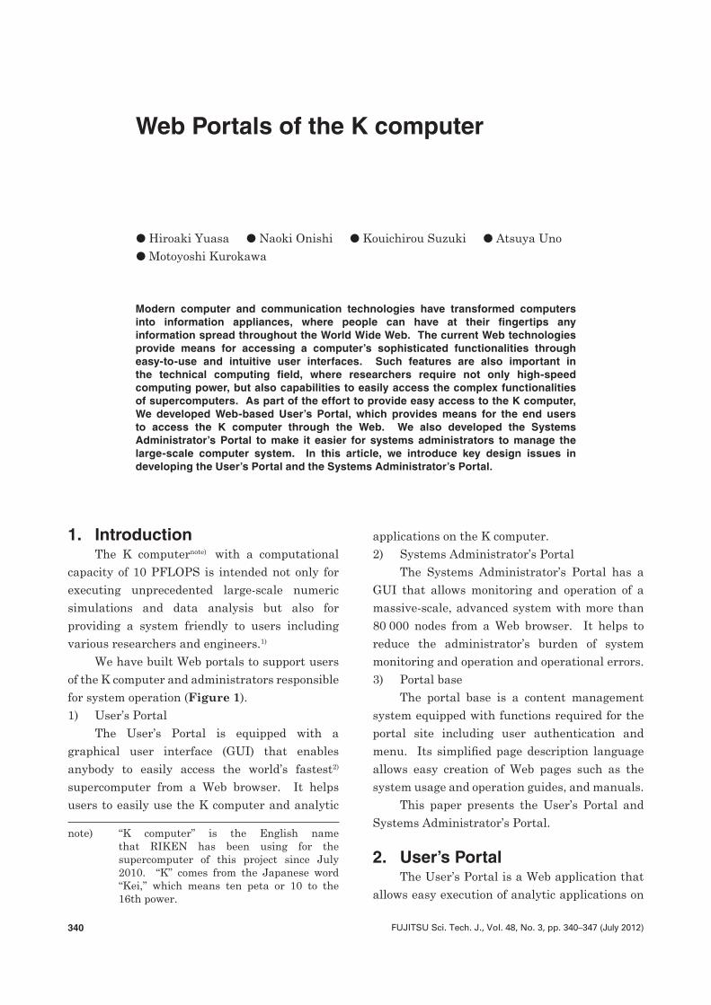
We have built Web portals to support users of the K computer and administrators responsible for system operation (Figure 1).1) User’s Portal
The User’s Portal is equipped with a graphical user interface (GUI) that enables anybody to easily access the world’s fastest2)
supercomputer from a Web browser. It helps users to easily use the K computer and analytic
note)i “K computer” is the English name that RIKEN has been using for the supercomputer of this project since July 2010. “K” comes from the Japanese word “Kei,” which means ten peta or 10 to the 16th power.
applications on the K computer.2) Systems Administrator’s Portal
The Systems Administrator’s Portal has a GUI that allows monitoring and operation of a massive-scale, advanced system with more than 80 000 nodes from a Web browser. It helps to reduce the administrator’s burden of system monitoring and operation and operational errors.3) Portal base
The portal base is a content management system equipped with functions required for the portal site including user authentication and menu. Its simplified page description language allows easy creation of Web pages such as the system usage and operation guides, and manuals.
This paper presents the User’s Portal and Systems Administrator’s Portal.
2. User’s PortalThe User’s Portal is a Web application that
allows easy execution of analytic applications on
341FUJITSU Sci. Tech. J., Vol. 48, No. 3 (July 2012)
H. Yuasa et al.: Web Portals of the K computer
the K computer from a Web browser or the user’s own program. The major functions include:• Job submission• Job status indication and basic job
operations• Basic fi le operations on the K computer• File transfer with client PC• Program compilation and link operations
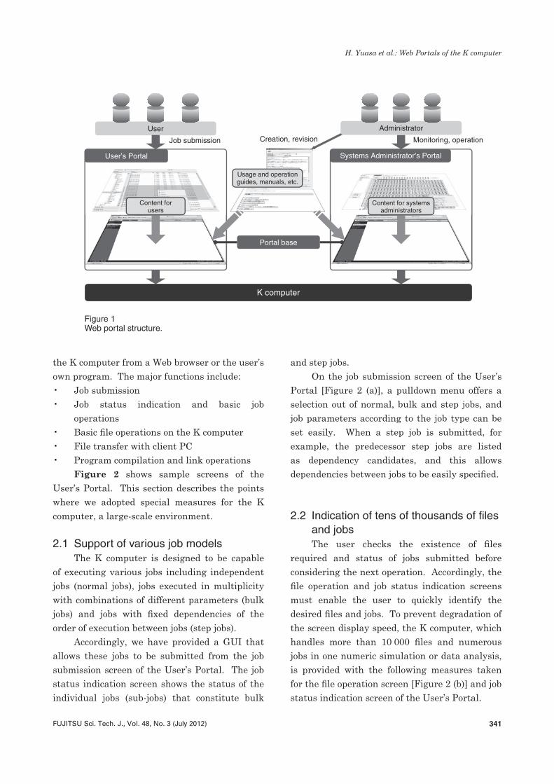
Figure 2 shows sample screens of the User’s Portal. This section describes the points where we adopted special measures for the K computer, a large-scale environment.
2.1 Support of various job modelsThe K computer is designed to be capable
of executing various jobs including independent jobs (normal jobs), jobs executed in multiplicity with combinations of different parameters (bulk jobs) and jobs with fi xed dependencies of the order of execution between jobs (step jobs).
Accordingly, we have provided a GUI that allows these jobs to be submitted from the job submission screen of the User’s Portal. The job status indication screen shows the status of the individual jobs (sub-jobs) that constitute bulk
and step jobs.On the job submission screen of the User’s
Portal [Figure 2 (a)], a pulldown menu offers a selection out of normal, bulk and step jobs, and job parameters according to the job type can be set easily. When a step job is submitted, for example, the predecessor step jobs are listed as dependency candidates, and this allows dependencies between jobs to be easily specifi ed.
2.2 Indication of tens of thousands of fi les and jobsThe user checks the existence of fi les
required and status of jobs submitted before considering the next operation. Accordingly, the fi le operation and job status indication screens must enable the user to quickly identify the desired fi les and jobs. To prevent degradation of the screen display speed, the K computer, which handles more than 10 000 fi les and numerous jobs in one numeric simulation or data analysis, is provided with the following measures taken for the fi le operation screen [Figure 2 (b)] and job status indication screen of the User’s Portal.
Figure 1Web portal structure.
Portal base
K computer
User’s Portal Systems Administrator’s Portal
Usage and operationguides, manuals, etc.
Creation, revisionUser Administrator
Job submission Monitoring, operation
Content for systemsadministrators
Content forusers
342 FUJITSU Sci. Tech. J., Vol. 48, No. 3 (July 2012)
H. Yuasa et al.: Web Portals of the K computer
2.2.1 Partial screen update by asynchronous communication
The User’s Portal of the K computer makes use of the Asynchronous JavaScript + XML (Ajax)3) technology to adopt a screen update technique that redraws only the necessary screen areas according to user operation.
Ajax is a technology that uses the hypertext transfer protocol (HTTP) communication function of JavaScript for asynchronous communication with the server to partially redraw the screen. Unlike the existing Web applications that involve screen transitions, this technology does not erase an entire screen for every operation, which makes it popular for use in Web applications that make a point of interactivity.
With this new technique of screen update, the User’s Portal features reduced screen generation processing by the server, less data transfer between the server and client and
reduced drawing processing of Web browsers as compared with the existing user’s portals, which update an entire screen. The advanced GUI based on Ajax allows the user to operate fi les and jobs in the same way as Windows Explorer.
2.2.2 Narrowing of listingsDisplaying tens of thousands of fi les or jobs
on the screen at one time increases the amount of data transfer from the server. In addition, a Web browser applies a certain style when fi les or jobs are displayed, which uses more memory than just for the amount of data received from the server, leading to degradation of the display speed. As a result, user operability is also deteriorated as well.
To address this problem, the User’s Portal of the K computer adopts the following measures for smooth display and operation of enormous numbers of fi les and jobs.
Figure 2User’s Portal sample screens.
Job modelselection menu
Interface for specifying job dependencies
(b) File operation screen(a) Job submission screen
Paging button Filter by filenameFilter by filename
Predecessor job candidatesPredecessorjob exit code
Execution programspecification
Submit/output filespecification
343FUJITSU Sci. Tech. J., Vol. 48, No. 3 (July 2012)
H. Yuasa et al.: Web Portals of the K computer
1) Paged screen viewPaged view is used for both file operation
and job status indication screens. The maximum number of files or jobs displayed on one page is defined on the server in advance and the screen displays one page’s worth of files or jobs. The server caches the list information of files or jobs of all pages. The user’s paging button operation immediately transfers one page’s worth of file or job list information from the cache to be displayed on the screen.2) Filtering by filename pattern
Of the files in a directory, in many cases only some are files that the user wants to view. Accordingly, the file operation screen is provided with a function to narrow down the files to be displayed by specifying a filename pattern. This not only reduces the amount of data transfer from the server but also allows the user to easily select the files to view out of the enormous number of files and operate them.
2.3 Long-time processing for groups of large filesThe K computer assumes that the user
handles a few hundred Gbytes to a few tens of Tbytes of data. Operation (file copying, searching, archiving, etc.) of such large files is time-consuming and the Web browser may time out during the operation.
Accordingly, the User’s Portal uses an innovative processing sequence to prevent Web browser timeout in spite of operating a large amount of data, which is described below.1) Execution of long-time processing is
requested from the Web browser to the User’s Portal.
2) The User’s Portal starts long-time processing and returns a response to the Web browser without waiting for the completion of processing.
3) The Web browser shows an animation indicating “in process” and queries the User’s Portal to check whether or not the
long-time processing has been completed.4) The User’s Portal checks the progress
of the long-time processing and returns a processing complete or processing not complete response to the browser.
5) Upon reception of a processing complete response, the Web browser stops the animation indicating in process and shows the result of processing on the screen. If it receives a processing not complete response, it queries the User’s Portal again to check the processing situation.
6) Steps 4) and 5) are repeated until the long-time processing is completed.
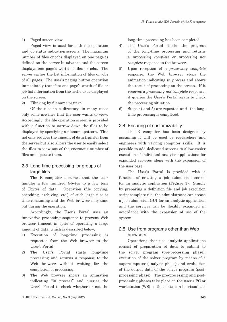
2.4 Ensuring of customizabilityThe K computer has been designed by
assuming it will be used by researchers and engineers with varying computer skills. It is possible to add dedicated screens to allow easier execution of individual analytic applications for expanded services along with the expansion of the user base.
The User’s Portal is provided with a function of creating a job submission screen for an analytic application (Figure 3). Simply by preparing a definition file and job execution script template file, the administrator can create a job submission GUI for an analytic application and the services can be flexibly expanded in accordance with the expansion of use of the system.
2.5 Use from programs other than Web browsersOperations that use analytic applications
consist of preparation of data to submit to the solver program (pre-processing phase), execution of the solver program by means of a supercomputer (analysis phase) and evaluation of the output data of the solver program (post-processing phase). The pre-processing and post-processing phases take place on the user’s PC or workstation (WS) so that data can be visualized
344 FUJITSU Sci. Tech. J., Vol. 48, No. 3 (July 2012)
H. Yuasa et al.: Web Portals of the K computer
and the analysis results can be checked in an interactive manner. For this reason, we consider that allowing consecutive execution of the processing of the three phases across different execution environments will lead to improved effi ciency of the user’s operations.
The User’s Portal has the screen control function for Web browsers separated from the function of executing user operations on the K computer to allow the K computer to be operated from client programs other than Web browsers. The latter function can be called from a program other than a Web browser via a Web service. In addition, to enable the user to easily create a client program for the K computer, a client library (in command and Perl-API formats) that runs on Windows, Linux and Mac OS X is provided. The user can seek to automate and improve the effi ciency of operations that use both PC/WS and the K computer by using the client library to create a script that runs on the PC or WS at hand.
3. Systems Administrator’s PortalThe Systems Administrator’s Portal is a Web
application intended for systems administrators
that allows them to easily monitor and manage compute nodes and storage systems of the K computer from a Web browser. Major features include:• Indication of operational status of compute
nodes• Indication of CPU, memory and disk usage• Power supply control of systems and
compute nodes• Indication and operation of a job list• Indication of error information list• Management of user information and
indication of billing informationSample screens of the Systems
Administrator’s Portal are shown in Figures 4, 5 and 6. This section describes the measures taken in the development of the Systems Administrator’s Portal with the K computer, a large-scale environment, taken into consideration.
3.1 Large-scale node status indication with different logical and physical placementsTo optimize 6D mesh/torus network, the
K computer has different physical and logical placements of compute nodes. There are limits
Figure 3High customizability through application GUI customization function (User's Portal).
Portal baseUser’s Portal
commonoperation section
(a) Standard GUI by definition file
(b) Advanced GUI by Perl script
Creation of parameter submission form
Administrator
Jobexecution
script(template)
Jobexecution
script(template)
Jobexecution
script
Jobexecution
script
Job submission screen(analytic application-specific)
Job submission screen
(general)
Creation/customization
Job(analytic
application)
Job
Job submission
Job submission
Screen inputvalue embedding
Screen inputvalue embedding
Creation/customization
User
345FUJITSU Sci. Tech. J., Vol. 48, No. 3 (July 2012)
H. Yuasa et al.: Web Portals of the K computer
(Original is in Japanese)
Each point on X-Y coordinate divided into16 sections to indicate operational state ofcompute nodes on Z-axis.
System monitoring State of use Error notification User management Power supply management Partition management
Logout
Operational state (ALL)
Entire system
By rack
By node
Global FS
Operation of all racks (physical)
Operation of all racks (logical)
Temperature of all racks (physical)
Temperature by rack
All nodes
By OSS
RAID status
By resource unit
Last data update: January 4, 2012 19:56:20
Indication forNode group
Resource unit
Selected cabinet
Deselect
Job list
Screen transition
Memory Disk
All resource units Switch
Job management sub-node Tofu 3D
Tofu unit
Click to select the intended cabinet.• Boot group ID : 0×160b-----State in Tofu unit-----• Number of nodes executing job : 0• Number of nodes in process of staging : 0• Number of nodes on standby for job : 192• Number of nodes with power OFF : 0• Number of disabled nodes : 0• Number of nodes with error : 0
Power ON (executing job) Power ON (in process of staging) Power ON (on standby for job) Error detected Power OFFDisable
CPUOperational state
(Original is in Japanese)
Executing job In process of staging On standby for job Error detected Power OFFUnable to be assigned job (disabled)
Operational state (ALL)
Entire system
By rack
By node
Global FS
Operation of all racks (physical)
Operation of all racks (logical)
Temperature of all racks (physical)
Temperature by rack
All nodes
By OSS
RAID status
By resource unit
System monitoring State of use Error notification User management Power supply management Partition management Support function
Click to switch from channel to rack • Boot group ID : 0×170e• Number of nodes executing job : 96• Number of nodes in process of staging : 0• Number of nodes on standby for job : 0
• Number of nodes with power OFF : 0
• Number of disabled nodes : 0• Number of nodes with error detected : 0
Indication of number of nodes in rack
Number of racks
Number of compute nodes
Operational state ofeach rack indicated bycolor and value
All nodes executing job: 519Some nodes with error detected: 6
All nodes on standby: 284Some nodes with power OFF: 47
All nodes power OFF: 1Some nodes disabled:1
All nodes in process of staging: 2Some nodes executing job: 4
Logout
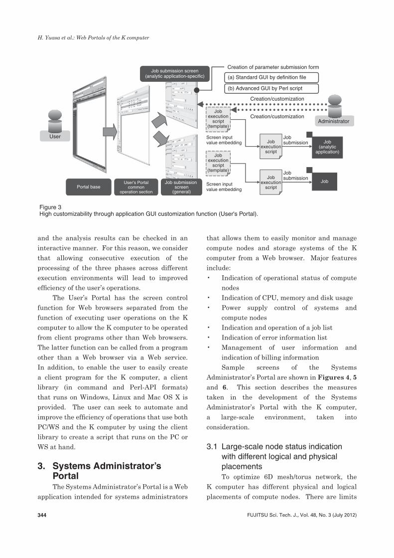
Figure 4Operational state indication for individual resource units (Systems Administrator’s Portal).
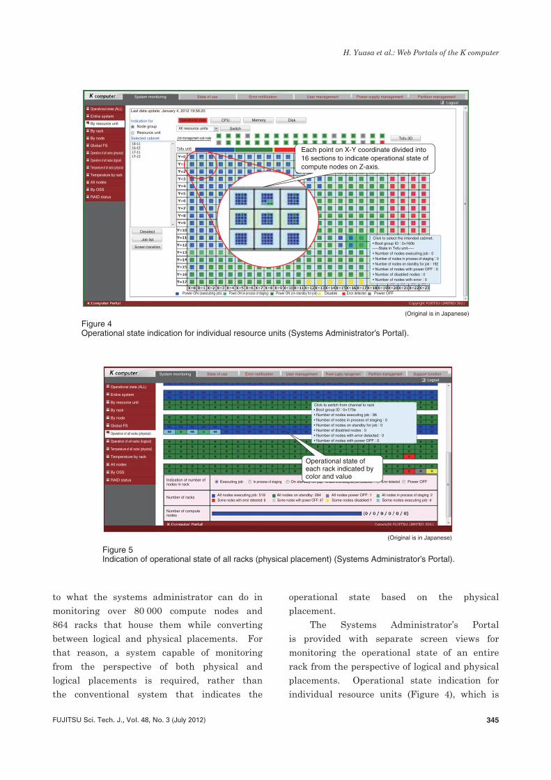
Figure 5Indication of operational state of all racks (physical placement) (Systems Administrator’s Portal).
to what the systems administrator can do in monitoring over 80 000 compute nodes and 864 racks that house them while converting between logical and physical placements. For that reason, a system capable of monitoring from the perspective of both physical and logical placements is required, rather than the conventional system that indicates the
operational state based on the physical placement.
The Systems Administrator’s Portal is provided with separate screen views for monitoring the operational state of an entire rack from the perspective of logical and physical placements. Operational state indication for individual resource units (Figure 4), which is
346 FUJITSU Sci. Tech. J., Vol. 48, No. 3 (July 2012)
H. Yuasa et al.: Web Portals of the K computer
one screen for logical placement, has each point on the X-Y coordinate divided into 16 sections to show the operational state of all compute nodes including the Z-axis direction. This is in view of assignment of jobs to a logically continuous 3D torus view space. Indication of the operational state of all racks (physical placement) (Figure 5), a screen for physical placement, shows the operational state of each rack represented by a color and value of an icon.
The systems administrator can visually acquire the necessary information from screen views that suit the respective operations. To monitor a job, for example, a screen for logical placement can be used to monitor the state of the job assigned to a continuous region. In addition, the compute node that is executing the job to be monitored can be selected and associated with the CPU, memory or disk usage for monitoring the state. For maintenance, a screen for physical placement can be used to identify the locations that require replacement of parts. Furthermore, the screen providing temperature information makes it easier for the systems administrator to decide the surrounding temperature of failure
part for any abnormality.
3.2 Disk status monitoring of large-scale storageThe global file system of the K computer
has a data capacity of over 30 Pbytes and almost 100 000 disks are used in the entire system. When any disk fails, a backup disk is used for rebuilding and, after the failed disk has been replaced by a maintenance engineer, recovery (copy back) from the backup disk is carried out. Because of the vast number of disks, grasping the progress of rebuilding and copying back for each disk is cumbersome, which poses a problem.
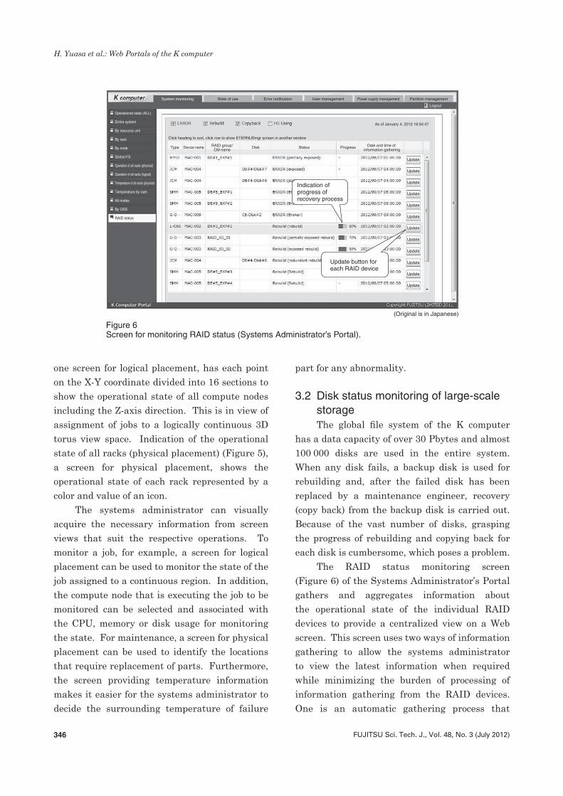
The RAID status monitoring screen (Figure 6) of the Systems Administrator’s Portal gathers and aggregates information about the operational state of the individual RAID devices to provide a centralized view on a Web screen. This screen uses two ways of information gathering to allow the systems administrator to view the latest information when required while minimizing the burden of processing of information gathering from the RAID devices. One is an automatic gathering process that
Update button foreach RAID device
Indication ofprogress ofrecovery process
(Original is in Japanese)
Operational state (ALL)
Entire system
By resource unit
By rack
By node
Global FS
Operation of all racks (physical)
Operation of all racks (logical)
Temperature of all racks (physical)
Temperature by rack
All nodes
By OSS
RAID status
System monitoring State of use Error notification User management Power supply management Partition management
Logout
Click heading to sort, click row to show ETERNUSmgr screen in another window
Type Disk Status Progress Date and time of information gathering
Device name RAID group/CM name
Update
Update
Update
Update
Update
Update
Update
Update
Update
Update
Update
Update
As of January 4, 2012 16:54:47
Figure 6Screen for monitoring RAID status (Systems Administrator’s Portal).
347FUJITSU Sci. Tech. J., Vol. 48, No. 3 (July 2012)
H. Yuasa et al.: Web Portals of the K computer
regularly gathers information from all RAID devices. The other is a process of information gathering from the individual RAID devices, which is activated by the administrator’s pressing the Update button provided on the screen for each RAID device and gathers the latest information from the intended RAID device for its indication.
This screen provides an at-a-glance view for exhaustive monitoring of the state of disks with any error in the entire system. The systems administrator can press the Update button when he or she wants to intensively monitor a RAID device and view the latest status of processing on that device. This enables the systems administrator to estimate when the disks will return to their normal state, which helps in planning operations of the system.
4. ConclusionThis paper has described the User’s Portal
and Systems Administrator’s Portal introduced in the K computer. These two Web portals can be used not only for the K computer but also for PC cluster systems and supercomputers that will follow the K computer in the future. Demand for technical computing is expected to grow in the future both in Japan and overseas. We are committed to continuing our efforts to improve operational effi ciency and reduce the burden on users and administrators of supercomputers by providing the User’s Portal and Systems Administrator’s Portal presented in this paper.
References1) Institute of Physical and Chemical Research
(RIKEN): The Development of the Next-Generation Supercomputer—Aim of System Development. (in Japanese).
http://www.nsc.riken.jp/project/nerai.html2) TOP500 SUPERCOMPUTER SITES: November
2011. http://www.top500.org/list/2011/113) Ajax: A New Approach to Web Applications. http://www.adaptivepath.com/ideas/ajax-new-
approach-web-applications
Hiroaki YuasaFujitsu Ltd.Mr. Yuasa is currently engaged in development and sales expansion of User’s Portal.
Atsuya UnoRIKENDr. Uno is engaged in coordinating development of system software.
Naoki OnishiFujitsu Ltd.Mr. Onishi is currently engaged in development and sales expansion of Systems Administrator’s Portal.
Motoyoshi KurokawaRIKENDr. Kurokawa is engaged in develop-ment of system as a whole.
Kouichirou SuzukiFujitsu Ltd.Mr. Suzuki is currently engaged in development and sales expansion of User’s Portal.
Recommended