Embed Size (px)
Citation preview

Electromagnetic TestingChapter 14- Electromagnetic Techniques for Primary Metals Application22th February 2015 大年初四My ASNT Level III Pre-Exam Preparatory Self Study Notes
Charlie Chong/ Fion Zhang

Charlie Chong/ Fion Zhang
Primary Metals
Charlie Chong/ Fion Zhang
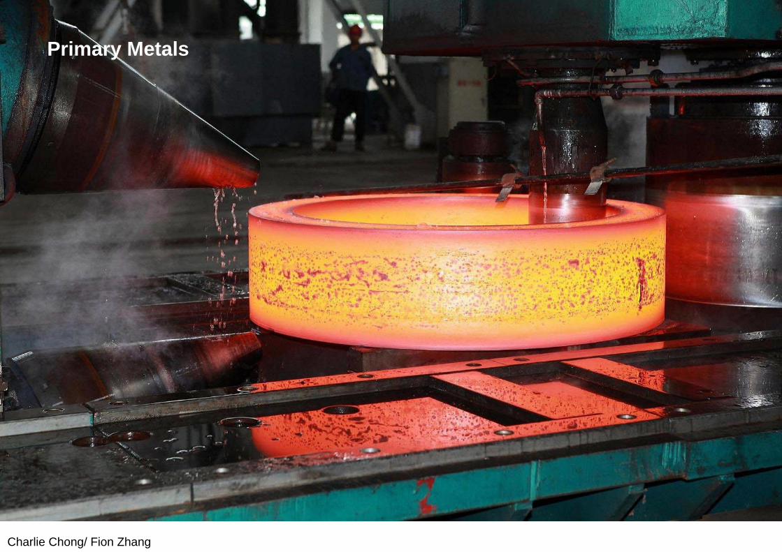
Primary Metals

Charlie Chong/ Fion Zhang
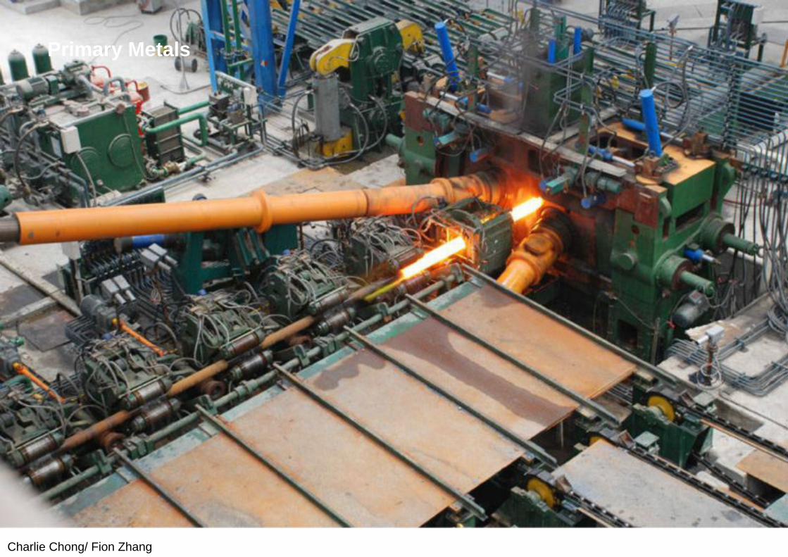
Primary Metals
Charlie Chong/ Fion Zhang
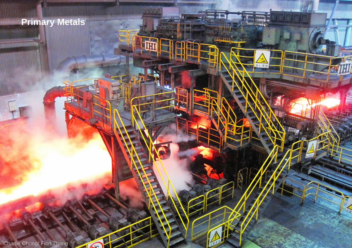
Primary Metals

Charlie Chong/ Fion Zhang
Primary Metals
Charlie Chong/ Fion Zhang
Primary Metals

Charlie Chong/ Fion Zhang
2015-2-22 大年初四

Charlie Chong/ Fion Zhang

Fion Zhang at Shanghai22th February 2015
Charlie Chong/ Fion Zhang Shanghai 上海

Charlie Chong/ Fion Zhang
Greek letter
Charlie Chong/ Fion Zhang
Chapter Thirteen:Electromagnetic Techniques for Material Identification

Charlie Chong/ Fion Zhang
14.1 PART 1. Electromagnetic Testing in Primary Metals Industries
The basic principles of electromagnetic testing were known in the nineteenth century and practical applications of electromagnetic techniques have been commonplace in the metals industry since 1930. Eddy current testing has evolved from relatively simple devices for metal sorting to complex, automated test systems as part of manufacturing processes. Electromagnetic techniques offer simplicity, low cost, noncontact and couplant free operation, high speed and high temperature capabilities.
They are widely used in all types of industries to evaluate the quality of materials and components, including both ferritic and non-ferritic metals. The total number of tests performed annually by these techniques may exceed that of all other nondestructive test techniques.

Charlie Chong/ Fion Zhang
Because of the skin effect, which limits the depth of penetration, eddy current testing is limited to surface and near surface evaluation of materials and products.
Both eddy current and magnetic techniques are preferred in the steel industry throughout the world for inline surface testing of bars, billets and tubes at production speeds. The eddy current technique is used by the metals industry for the inline testing of hot wires at high production speeds, often in excess of 120 m·s–1 (265 mi·h–1 ).
Electromagnetic test techniques find their application in all stages of forming, shaping and heat treating of metals and alloys, where the effectiveness of processing steps can be quickly evaluated. Materials damaged during processing can be detected and removed from production without incurring further processing costs. Thermal treatments such as annealing, normalizing, hardening, case hardening and other heat treating processes can be monitored directly in many instances.

Charlie Chong/ Fion Zhang
14.1.1 Eddy Current versus Magnetic TestingMetals are said to be ferromagnetic if, like iron (ferro- comes from the Latin word for iron), they can be magnetized. Ferromagnetic metals include iron, cobalt and nickel. Non-ferromagnetic metals include copper and aluminum.
Magnetic techniques such as magnetic flux leakage and magnetic particle testing can be used only on metals that can be magnetized — on steel, not aluminum.
On the other hand, eddy current testing can be used on all electrically conductive materials - magnetic and nonmagnetic. For this reason, eddy current testing is extensively used in factories that manufacture nonmagnetic but electrically conductive materials and components, such as aluminum and copper.
Charlie Chong/ Fion Zhang
The anisotropic and highly nonlinear behavior of ferromagnetic materials during magnetization tends to generate eddy current signals that are difficult to interpret. For this reason, ferromagnetic objects tested with the eddy current technique are often magnetically saturated, making them behave like nonmagnetic objects.
Keypoints:Saturated magnetic object, the relative magnetic permeability approaches or equal to one. (µr=µ/µo = 1)
Charlie Chong/ Fion Zhang
14.1.2 Current TestingEddy current techniques are widely used to test materials and components at high temperature. A differential technique with encircling coils is used to perform continuous process testing of hot rolled wires and rods in many steel mills around the world. Testing of hot steel billets (round and square) is also performed using eddy current probes. Both non-rotating and rotating probes can the hot surface.
(I) Technique Developments
■ Pulsed and Multi-frequency Techniques.Many complex eddy current test problems can be solved through the application of pulsed and multi-frequency eddy current techniques, as in the nondestructive measurement of case carburized and case hardened thickness in bearing components.
Charlie Chong/ Fion Zhang
■ Inversion of Eddy Current Data.Separating a desired variable from eddy current signals influenced by many undesirable variables is difficult despite advances in signal processing. Improvements in the reliability of online eddy current tests have been implemented mainly through eddy current signal processing techniques.
■ Phase Measurement. Many industrial applications use the amplitude of an eddy current signal to judge the product quality and do not use the equally valuable phase information from the same signal. Discontinuity depth in steel mills has typically been sized through amplitude only. The reliability of eddy current testing is improved if both amplitude and phase are used in developing accept/reject criteria.
Charlie Chong/ Fion Zhang
(II) Probe DesignsMultiple-sensor eddy current test heads have been developed to detect surface discontinuities in continuously cast slabs at high temperature. Phase discrimination can be used to suppress liftoff variations. The need for high speed data acquisition and probes contoured to fit complicated shapes has led to arrays of electronically scanned eddy current sensors rather than mechanical scanning with solitary sensors. Probes are designed to optimize operating parameters such as excitation frequency, test speed and liftoff. Successful design of eddy current tests requires accurate knowledge of electrical and magnetic characteristics of the test object and of the materials chosen for the construction of the probe. Even the best mathematical model is of little value without these material characteristics, which are often (depending on the application) nonlinear functions of magnetic flux density, space and temperature. Measurement of these characteristics in materials is important for optimization of eddy current tests.
Charlie Chong/ Fion Zhang
(III) Numerical ModelingMost practical eddy current problems are three-dimensional; some of them involve anisotropic materials and materials with nonlinear electrical and magnetic characteristics. Numerical models have shown success in handling nonlinear situations and awkward discontinuity boundaries, especially in two dimensional or axisymmetric test geometries.
Thanks to advances in digital computer technology since 1975, numerical modeling techniques have overcome most drawbacks associated withanalytical techniques. Numerical techniques are not limited by material nonlinearities and complex discontinuity shapes but by computer memory.
The numerical model has much in common with the experimental approach. Numerical analysis techniques, unlike analytical models, do not produce any equation as the solution but rather produce flux density, current density, phase and impedance plane trajectory plots. Numerical modeling techniques can predict the complex interactions between fields and discontinuities, interactions important for discontinuity characterization. Better eddy current tests and sensors have been designed with the help of advanced computer models.
Charlie Chong/ Fion Zhang
Keywords:The numerical model has much in common with the experimental approach. Numerical analysis techniques, unlike analytical models, do not produce any equation as the solution but rather produce flux density, current density, phase and impedance plane trajectory plots.
Charlie Chong/ Fion Zhang
14.1.3 Eddy Current ApplicationsPresented below are case histories representing typical applications of electromagnetic test techniques in the primary metals industry for the surface testing of bars, square billets and hot wires, rods and tubes. Most of these techniques are eddy current tests for hot metal. For efficient process control, eddy current testing is performed on steel while it is still hot because it is more efficient to detect discontinuities early in the process before the material undergoes further working. Eddy currents are induced by probe coils driven at medium to high frequencies. The coverage of the test surface depends on the probe motion relative to the test object. This relative motion can be achieved either by moving the test object or by moving the probe during testing. The applications in the rest of this chapter each illustrate an arrangement for this relative motion.
Charlie Chong/ Fion Zhang
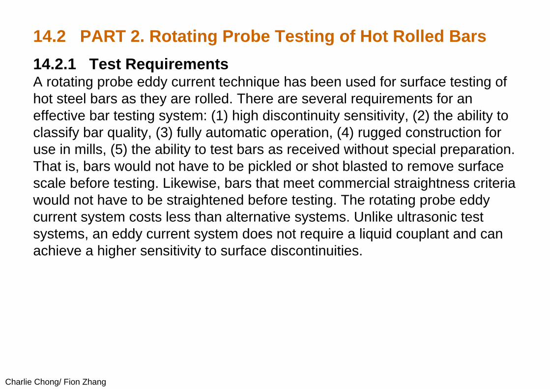
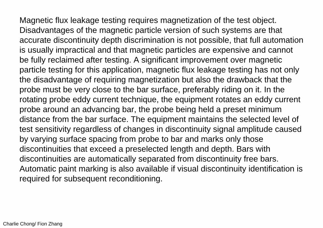
14.2 PART 2. Rotating Probe Testing of Hot Rolled Bars14.2.1 Test RequirementsA rotating probe eddy current technique has been used for surface testing of hot steel bars as they are rolled. There are several requirements for an effective bar testing system: (1) high discontinuity sensitivity, (2) the ability to classify bar quality, (3) fully automatic operation, (4) rugged construction for use in mills, (5) the ability to test bars as received without special preparation. That is, bars would not have to be pickled or shot blasted to remove surface scale before testing. Likewise, bars that meet commercial straightness criteria would not have to be straightened before testing. The rotating probe eddy current system costs less than alternative systems. Unlike ultrasonic test systems, an eddy current system does not require a liquid couplant and can achieve a higher sensitivity to surface discontinuities.
Charlie Chong/ Fion Zhang
Magnetic flux leakage testing requires magnetization of the test object. Disadvantages of the magnetic particle version of such systems are that accurate discontinuity depth discrimination is not possible, that full automation is usually impractical and that magnetic particles are expensive and cannot be fully reclaimed after testing. A significant improvement over magnetic particle testing for this application, magnetic flux leakage testing has not only the disadvantage of requiring magnetization but also the drawback that the probe must be very close to the bar surface, preferably riding on it. In the rotating probe eddy current technique, the equipment rotates an eddy current probe around an advancing bar, the probe being held a preset minimum distance from the bar surface. The equipment maintains the selected level of test sensitivity regardless of changes in discontinuity signal amplitude caused by varying surface spacing from probe to bar and marks only those discontinuities that exceed a preselected length and depth. Bars with discontinuities are automatically separated from discontinuity free bars. Automatic paint marking is also available if visual discontinuity identification is required for subsequent reconditioning.
Charlie Chong/ Fion Zhang
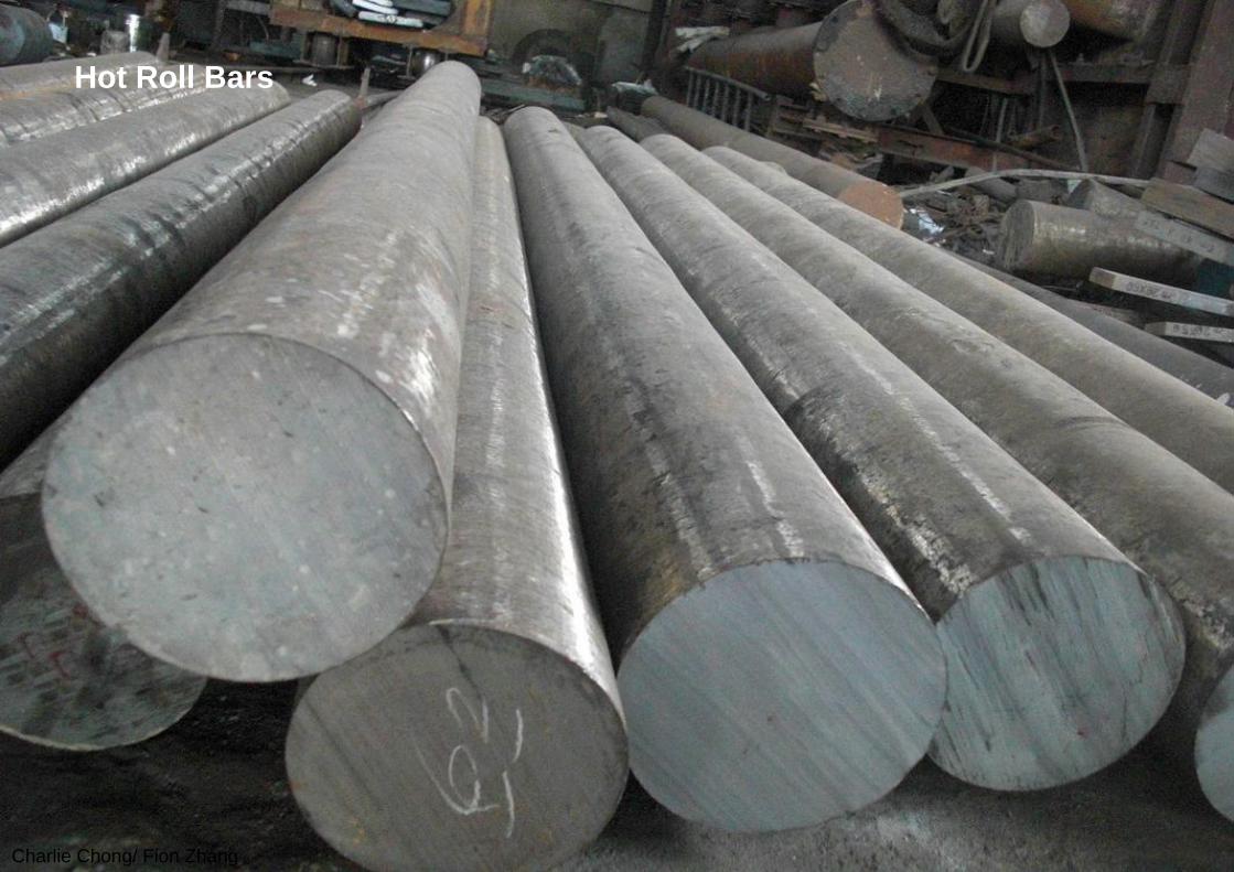
Hot Roll Bars
Charlie Chong/ Fion Zhang
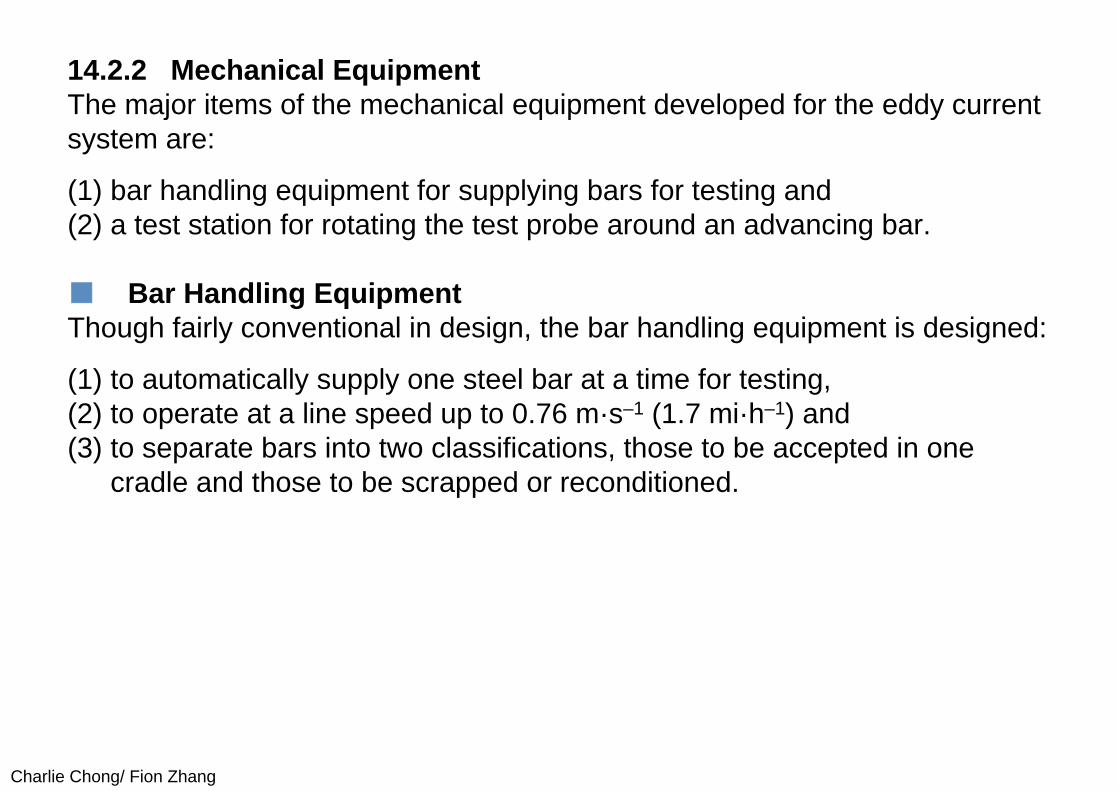
14.2.2 Mechanical EquipmentThe major items of the mechanical equipment developed for the eddy current system are:
(1) bar handling equipment for supplying bars for testing and (2) a test station for rotating the test probe around an advancing bar.
■ Bar Handling EquipmentThough fairly conventional in design, the bar handling equipment is designed:
(1) to automatically supply one steel bar at a time for testing, (2) to operate at a line speed up to 0.76 m·s–1 (1.7 mi·h–1) and (3) to separate bars into two classifications, those to be accepted in one
cradle and those to be scrapped or reconditioned.
Charlie Chong/ Fion Zhang
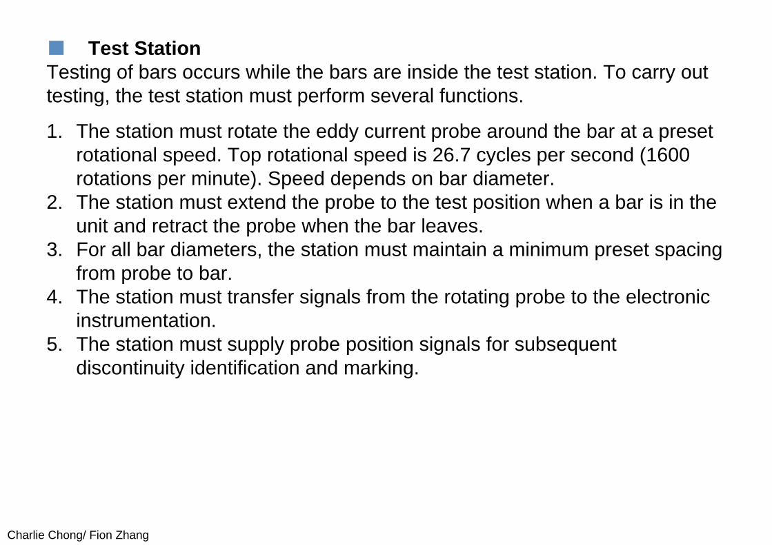
■ Test StationTesting of bars occurs while the bars are inside the test station. To carry out testing, the test station must perform several functions.
1. The station must rotate the eddy current probe around the bar at a preset rotational speed. Top rotational speed is 26.7 cycles per second (1600 rotations per minute). Speed depends on bar diameter.
2. The station must extend the probe to the test position when a bar is in the unit and retract the probe when the bar leaves.
3. For all bar diameters, the station must maintain a minimum preset spacing from probe to bar.
4. The station must transfer signals from the rotating probe to the electronic instrumentation.
5. The station must supply probe position signals for subsequent discontinuity identification and marking.
Charlie Chong/ Fion Zhang
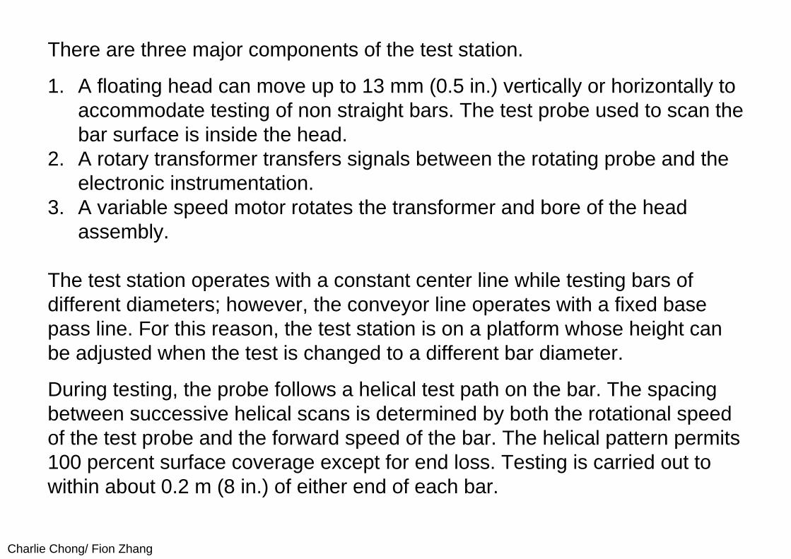
There are three major components of the test station.
1. A floating head can move up to 13 mm (0.5 in.) vertically or horizontally to accommodate testing of non straight bars. The test probe used to scan the bar surface is inside the head.
2. A rotary transformer transfers signals between the rotating probe and the electronic instrumentation.
3. A variable speed motor rotates the transformer and bore of the head assembly.
The test station operates with a constant center line while testing bars of different diameters; however, the conveyor line operates with a fixed base pass line. For this reason, the test station is on a platform whose height can be adjusted when the test is changed to a different bar diameter.
During testing, the probe follows a helical test path on the bar. The spacing between successive helical scans is determined by both the rotational speed of the test probe and the forward speed of the bar. The helical pattern permits 100 percent surface coverage except for end loss. Testing is carried out to within about 0.2 m (8 in.) of either end of each bar.
Charlie Chong/ Fion Zhang
14.2.3 Electronic InstrumentationElectronic instrumentation for the bar tester consists of the following circuits:
(1) eddy current circuits for detecting the presence of discontinuities, (2) automatic gain control circuits for maintaining a constant test sensitivity, (3) signal processing circuits that function separately and together to
discriminate between noise and actual discontinuity signals and (4) marking circuits.

Charlie Chong/ Fion Zhang
(I) Discontinuity Detection
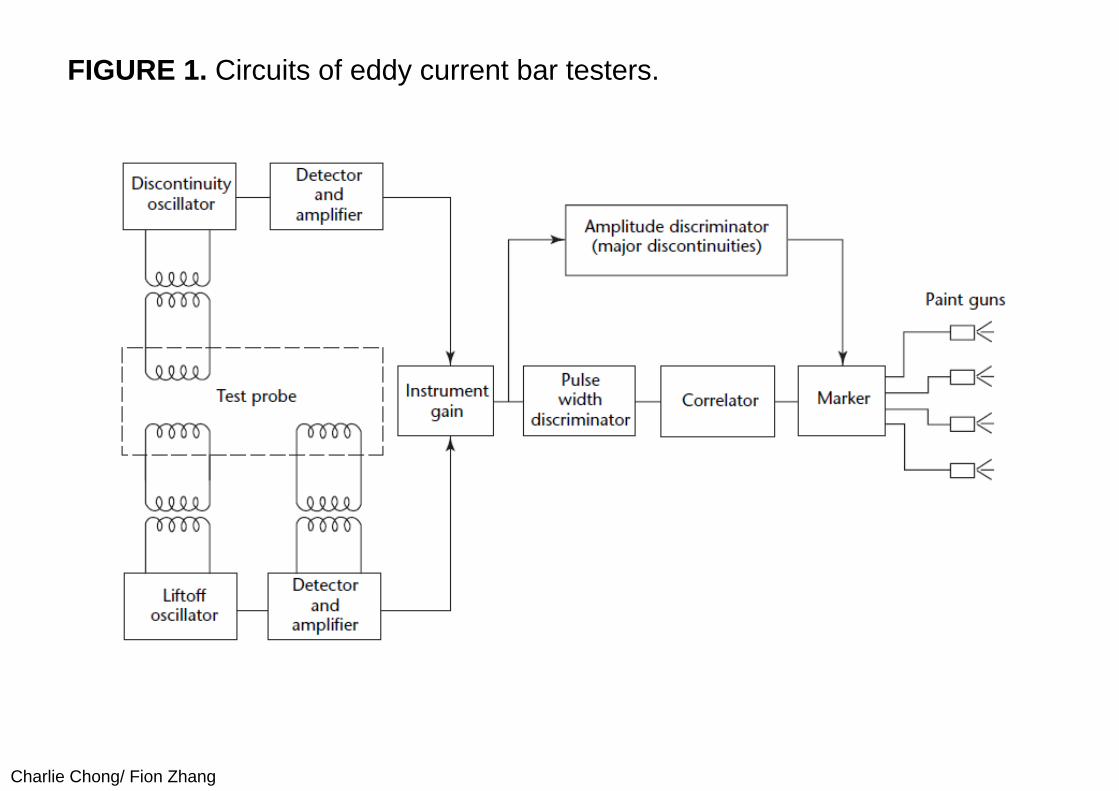
Figure 1 is a block diagram of the electronic instrumentation. The discontinuity detection circuits are coupled to the rotating probe through one channel of the three-channel rotary transformer. Electrical signals developed by the high frequency discontinuity oscillator and applied to coils in the test probe generate eddy currents on the bar surface. When a discontinuity is present on the bar surface, the orderly flow of eddy currents is disrupted; the deeper the discontinuity, the greater its effect on the eddy current flow. Detection, amplification and filtering circuits then develop electrical signals that indicate the presence of discontinuities and provide a signal amplitude proportional to discontinuity depth for processing by subsequent circuits to assess discontinuity severity.
Charlie Chong/ Fion Zhang
FIGURE 1. Circuits of eddy current bar testers.
Charlie Chong/ Fion Zhang
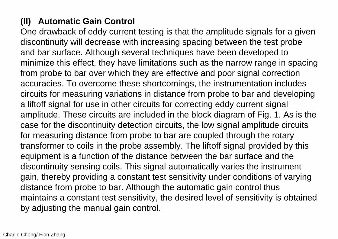
(II) Automatic Gain ControlOne drawback of eddy current testing is that the amplitude signals for a given discontinuity will decrease with increasing spacing between the test probe and bar surface. Although several techniques have been developed to minimize this effect, they have limitations such as the narrow range in spacing from probe to bar over which they are effective and poor signal correction accuracies. To overcome these shortcomings, the instrumentation includes circuits for measuring variations in distance from probe to bar and developing a liftoff signal for use in other circuits for correcting eddy current signal amplitude. These circuits are included in the block diagram of Fig. 1. As is the case for the discontinuity detection circuits, the low signal amplitude circuits for measuring distance from probe to bar are coupled through the rotary transformer to coils in the probe assembly. The liftoff signal provided by this equipment is a function of the distance between the bar surface and the discontinuity sensing coils. This signal automatically varies the instrument gain, thereby providing a constant test sensitivity under conditions of varying distance from probe to bar. Although the automatic gain control thus maintains a constant test sensitivity, the desired level of sensitivity is obtained by adjusting the manual gain control.
Charlie Chong/ Fion Zhang
(III) Signal Processing CircuitsIn the case of eddy current testing, noise signals can be caused by conditions such as surface roughness, scale and electrical interference, as well as short and shallow discontinuities that are not causes for rejection. These problems can be overcome through two techniques: pulse width discrimination and signal correlation. Gross discontinuity signals are processed by conventional amplitude discrimination. Finally, the system provides marking for subsequent visual location of discontinuities if required.
Charlie Chong/ Fion Zhang
(IV) Pulse Width DiscriminationThe pulse width discriminator identifies as a discontinuity indication any eddy
current signal that
(1) exceeds a preset amplitude and (2) decreases in amplitude from its peak value to half its peak value in less
than a predetermined time.
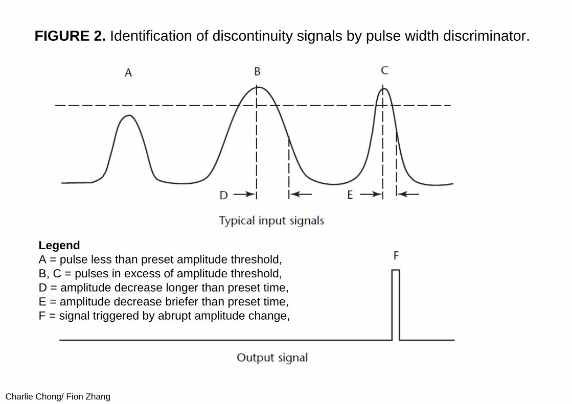
The corollary is that the discriminator disregards other signals. For simplicity, the period of time in which the amplitude decreases is referred to as signal width. Figure 2 can be used to illustrate the way in which pulse width discrimination works.
Charlie Chong/ Fion Zhang
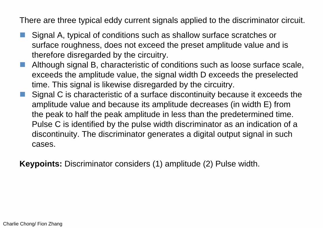
There are three typical eddy current signals applied to the discriminator circuit.
Signal A, typical of conditions such as shallow surface scratches or surface roughness, does not exceed the preset amplitude value and is therefore disregarded by the circuitry.
Although signal B, characteristic of conditions such as loose surface scale, exceeds the amplitude value, the signal width D exceeds the preselected time. This signal is likewise disregarded by the circuitry.
Signal C is characteristic of a surface discontinuity because it exceeds the amplitude value and because its amplitude decreases (in width E) from the peak to half the peak amplitude in less than the predetermined time. Pulse C is identified by the pulse width discriminator as an indication of a discontinuity. The discriminator generates a digital output signal in such cases.
Keypoints: Discriminator considers (1) amplitude (2) Pulse width.
Charlie Chong/ Fion Zhang
FIGURE 2. Identification of discontinuity signals by pulse width discriminator.
LegendA = pulse less than preset amplitude threshold,B, C = pulses in excess of amplitude threshold,D = amplitude decrease longer than preset time,E = amplitude decrease briefer than preset time,F = signal triggered by abrupt amplitude change,
Charlie Chong/ Fion Zhang
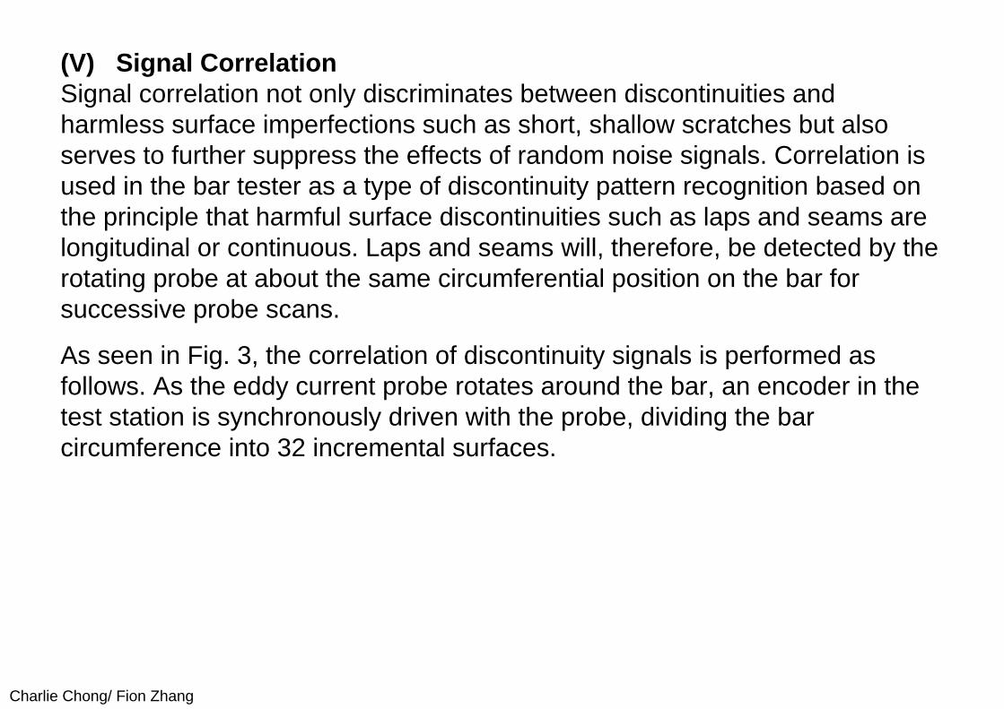
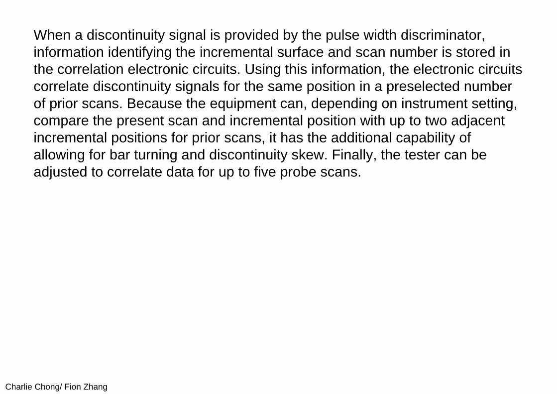
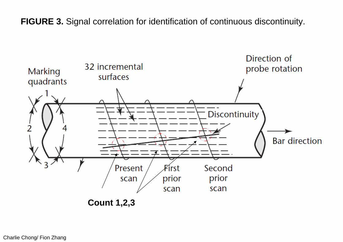
(V) Signal CorrelationSignal correlation not only discriminates between discontinuities and harmless surface imperfections such as short, shallow scratches but also serves to further suppress the effects of random noise signals. Correlation is used in the bar tester as a type of discontinuity pattern recognition based on the principle that harmful surface discontinuities such as laps and seams are longitudinal or continuous. Laps and seams will, therefore, be detected by the rotating probe at about the same circumferential position on the bar for successive probe scans.
As seen in Fig. 3, the correlation of discontinuity signals is performed as follows. As the eddy current probe rotates around the bar, an encoder in the test station is synchronously driven with the probe, dividing the bar circumference into 32 incremental surfaces.
Charlie Chong/ Fion Zhang
When a discontinuity signal is provided by the pulse width discriminator, information identifying the incremental surface and scan number is stored in the correlation electronic circuits. Using this information, the electronic circuits correlate discontinuity signals for the same position in a preselected number of prior scans. Because the equipment can, depending on instrument setting, compare the present scan and incremental position with up to two adjacent incremental positions for prior scans, it has the additional capability of allowing for bar turning and discontinuity skew. Finally, the tester can be adjusted to correlate data for up to five probe scans.
Charlie Chong/ Fion Zhang
FIGURE 3. Signal correlation for identification of continuous discontinuity.
Count 1,2,3
Charlie Chong/ Fion Zhang
(VI) Major DiscontinuityDiscontinuities that are deep but short, such as scabs and slivers, occur within only one probe scan and are processed in a conventional manner by amplitude discrimination. Figure 1 shows the block diagram location of these circuits. Because discontinuities of this type usually greatly exceed the amplitude of noise signals as well as correlated signals, they can be readily detected by amplitude level discrimination techniques. Signals of this type bypass the pulse width discriminator and correlation circuits.

Charlie Chong/ Fion Zhang
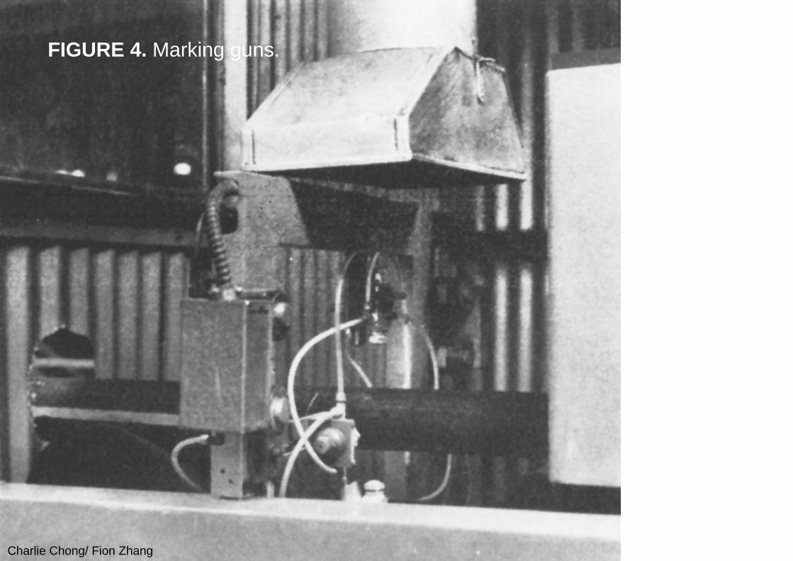
(VII) MarkingThe system includes provision for accurate discontinuity marking so that the discontinuities identified by the electronic circuits can be visually located for purposes such as subsequent bar reconditioning. The essentials of the marking equipment are as follows. Four paint guns are arranged around the circumference of the bar, each gun being centered in a quadrant of the bar (Fig. 3). The marking circuits (Fig. 1) process signals from the major discontinuity and correlator circuits and provide a paint mark in the quadrant where the discontinuity is located. An electrical signal from an encoder driven by the conveyor line delays marking until the anomalous area of the bar reaches the marking guns. In Fig. 4, the gun in the foreground is seen spraying a white stripe in a quadrant where the electronic circuits identify a discontinuity.
Charlie Chong/ Fion Zhang
FIGURE 4. Marking guns.
Charlie Chong/ Fion Zhang
Automated NDT Marking
Charlie Chong/ Fion Zhang
(VIII) CalibrationBefore the test is begun, the operator adjusts the equipment for bar diameter, metallurgical grade of the bars and the surface test requirements. To simplify adjustments for bar diameter, the controls and readouts for test station height, probe rotational speed and conveyor line speed are calibrated in terms of bar diameter. Adjusting for metallurgical grade is simple, usually requiring only a slight readjustment of two potentiometers to provide readings for on bar and off bar, respectively. Surface test requirements can be stated in terms of minimum depth of discontinuity to be marked and for continuous or seam type discontinuities, the minimum length to be marked. Thus, the setting for the desired test is obtained by adjusting the sensitivity potentiometer and the switch for discontinuity length. At the beginning of each turn, an overall check of equipment operation can be made by inserting a calibration fixture into the test station. This fixture has an accurately machined 50 mm (2 in.) diameter round section shifted off the center line of the test station. On the surface are accurately machined artificial discontinuities. The off center round section and the artificial discontinuities make it easier for the operator to quickly check a number of mechanical and electronic features of the equipment.
Charlie Chong/ Fion Zhang
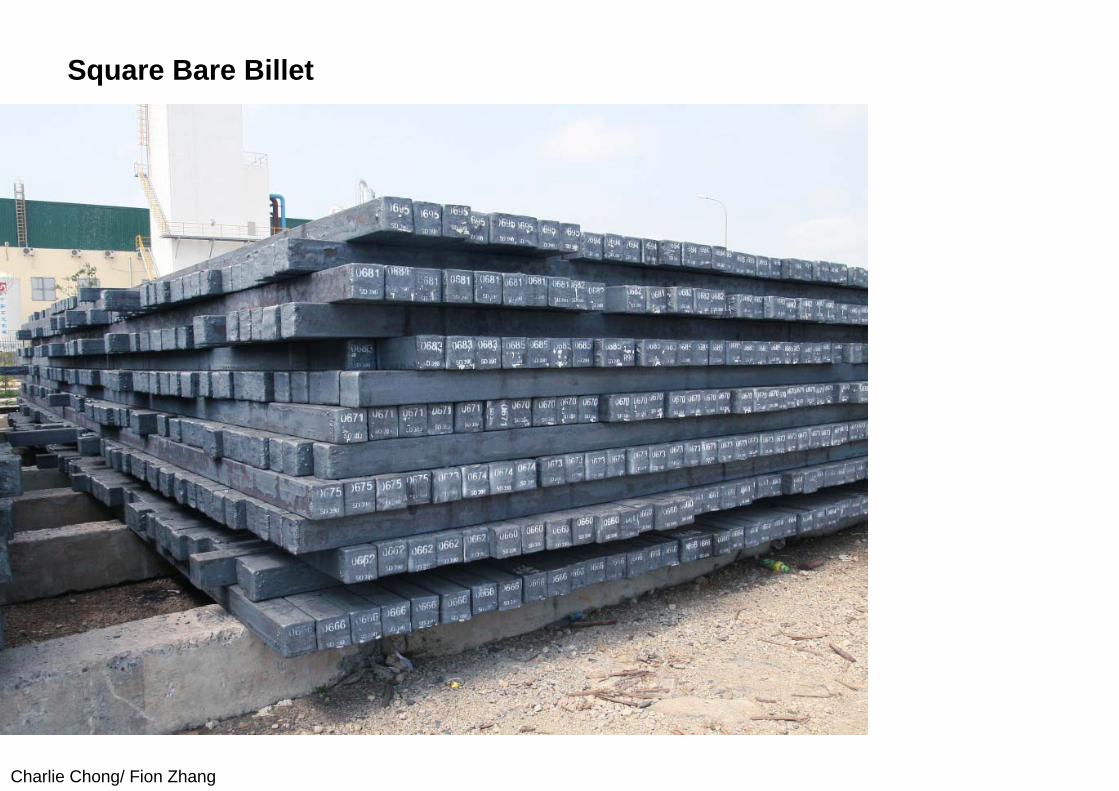
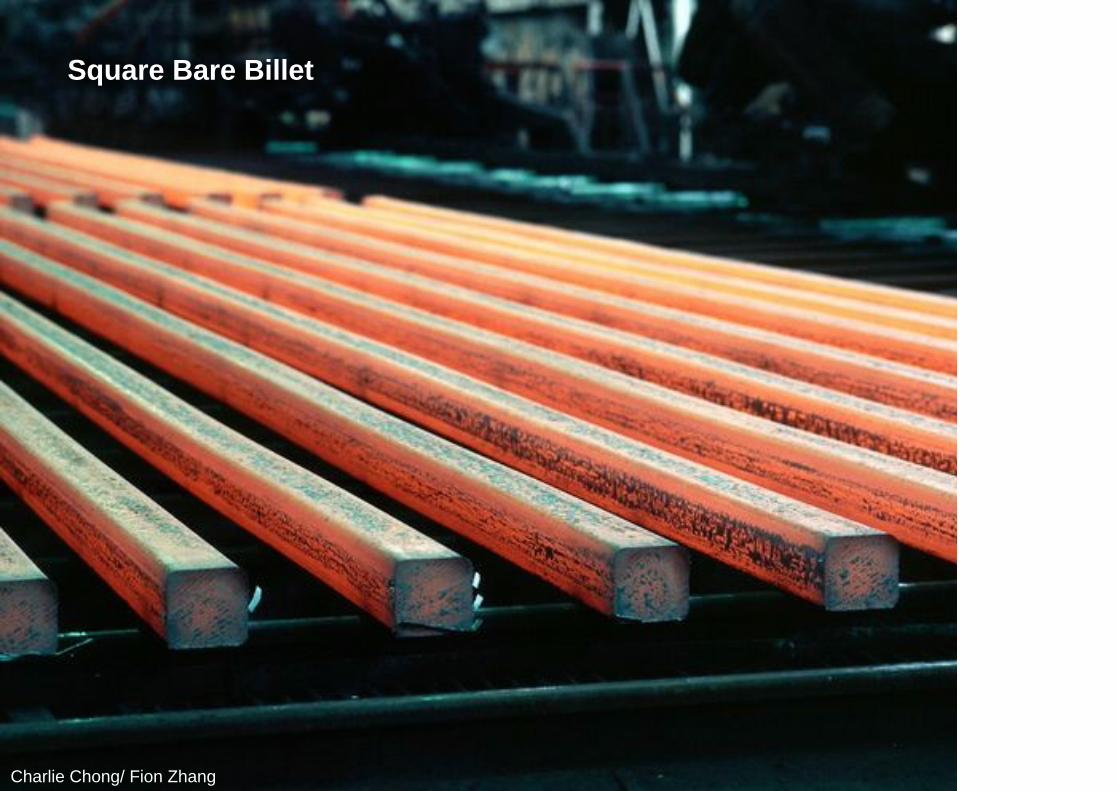
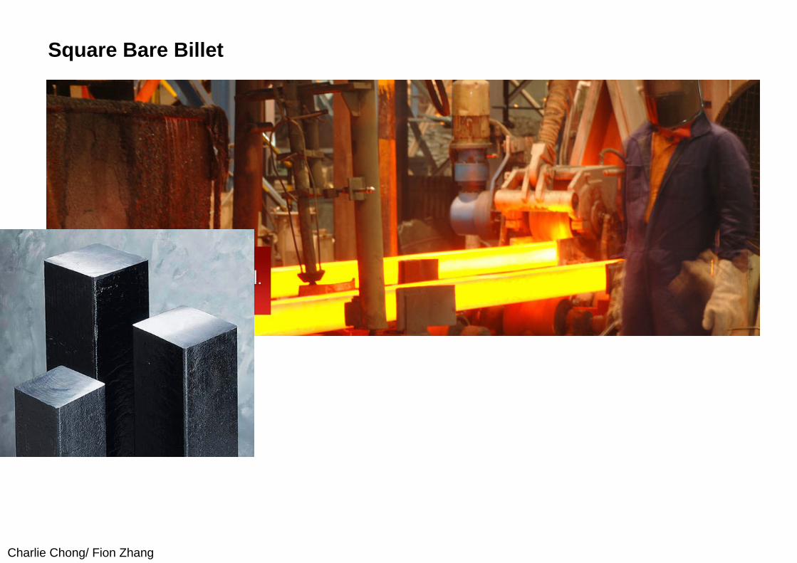
14.3 PART 3. Eddy Current Device for Total Surface Testing of Square Billets
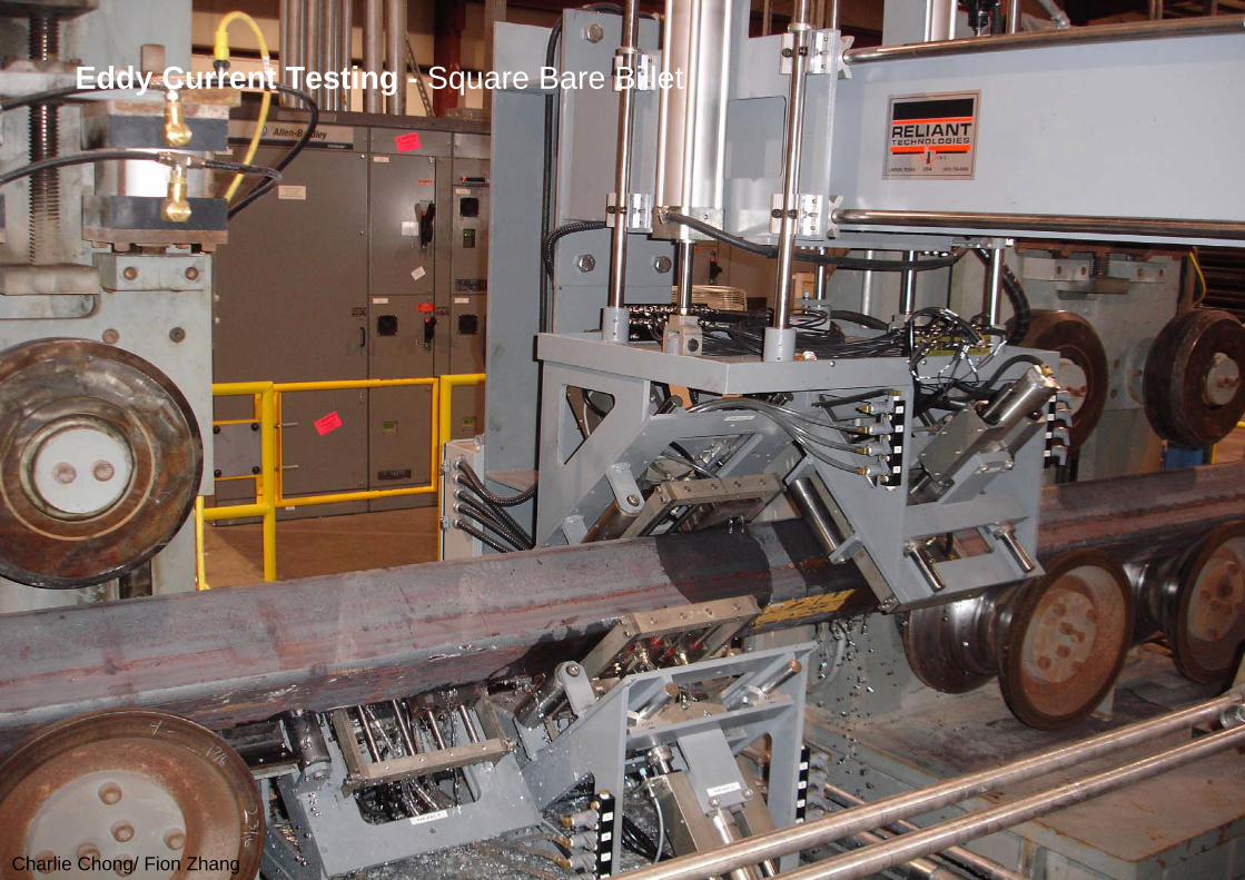
14.3.1 Integration of Test in Rolling ProcessEddy current testing can automatically inspect 100 percent of the surface of steel billets (having a square cross section) without the need of an operator’s judgment for interpreting test results. The system described here can detect seams, evaluate their severity and mark the location of those that exceed an acceptable depth. The key component is a scanning head assembly that keeps an eddy current probe in contact with and tangent to the billet surface at all locations around the periphery, including the corners. The machine is designed to test round cornered, square billets as they are rolled. This integration with the manufacturing process is an important step in the development of integrated automatic testing and conditioning systems. He inherent shortcomings of visual testing motivated the development of electronic techniques for measuring seam dimensions.
Charlie Chong/ Fion Zhang
One seam evaluation device uses a probe coil that causes eddy currents to flow in the test surface of the metal. Any discontinuity in the surface affects the electrical loading of the probe coil; in the case of seams, coil loading is inversely proportional to seam depth. For the detection of such discontinuities, absolute coil loading has little meaning. However, the changes in the loading of a coil as it crosses a discontinuity are significant. Therefore, relative movement between the probe coil and the product is required. In a manual test, this movement is achieved by moving the probe while holding the test object stationary. In an automatic test, the test object, the probe or both are moved.
Charlie Chong/ Fion Zhang
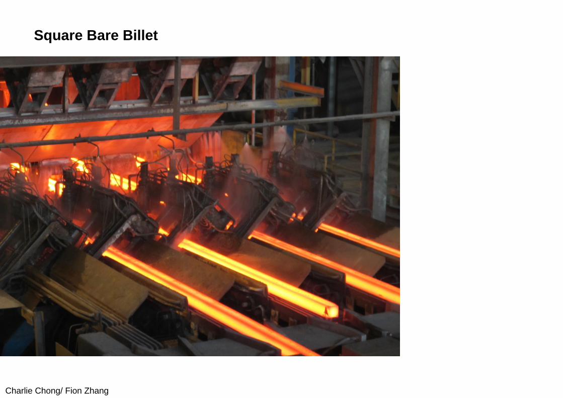
Square Bare Billet
Charlie Chong/ Fion Zhang
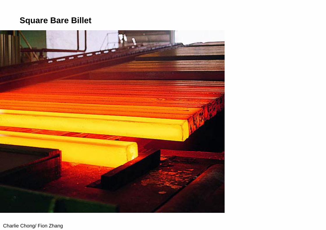
Square Bare Billet
Charlie Chong/ Fion Zhang
Square Bare Billet
Charlie Chong/ Fion Zhang
Square Bare Billet
Charlie Chong/ Fion Zhang
Square Bare Billet
Charlie Chong/ Fion Zhang
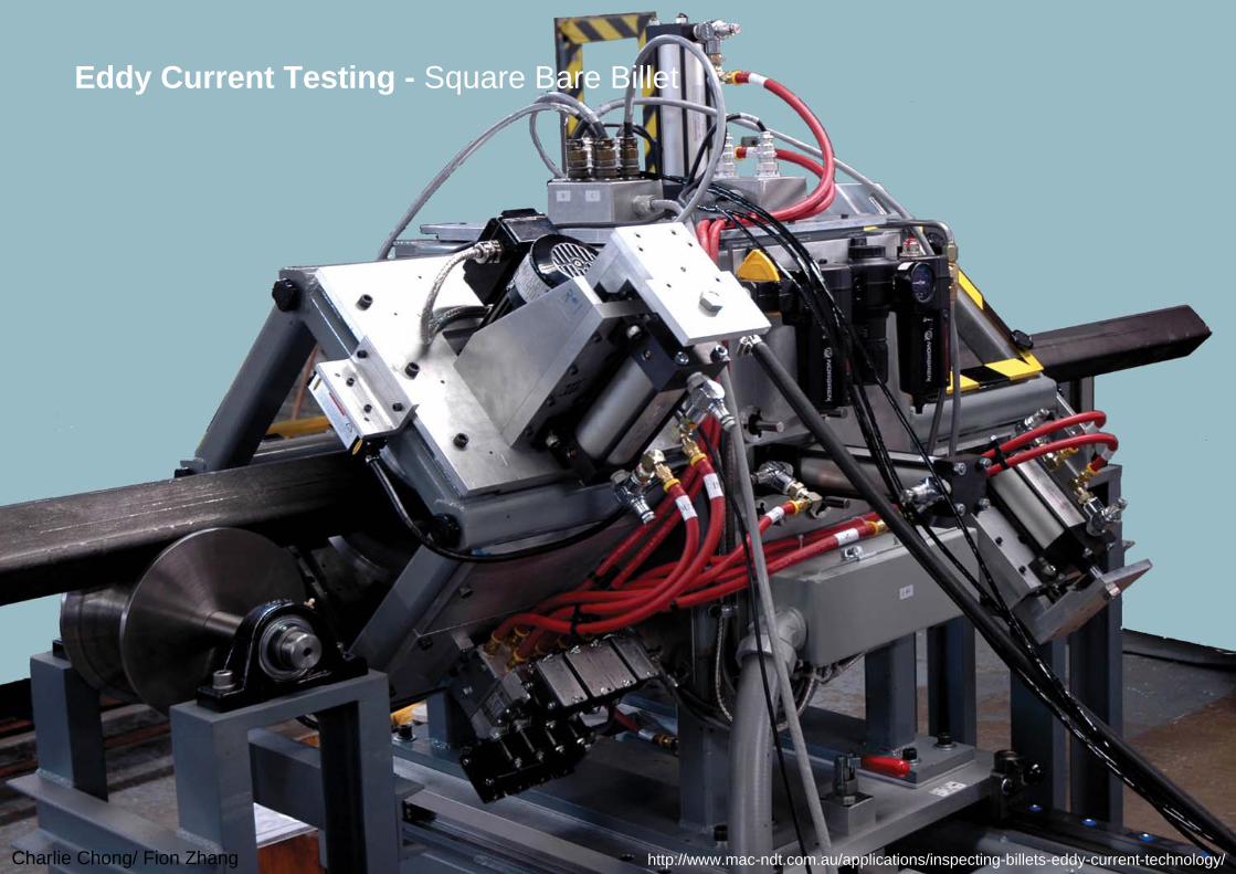
Eddy Current Testing - Square Bare Billet
http://www.mac-ndt.com.au/applications/inspecting-billets-eddy-current-technology/
Charlie Chong/ Fion Zhang
Eddy Current Testing - Square Bare Billet
Charlie Chong/ Fion Zhang
14.3.2 Application to RoundsThe diameter of the test object dictates the means of obtaining the relative movement necessary between the search probe and the test object.Machines designed to test small diameter bars rotate and propel the product while the probe is held stationary. For large diameter bars, pipe and billets, the probes are rotated around the product as it moves forward through the machine. Using the second means of obtaining relative motion, an installation or testing of rounds consists of two machines designed for 75 to 250 mm (3 to 10 in.) diameter, straightened solid product. These machines have been installed in a mill finishing line that also includes facilities for grit cleaning, straightening and grinding.
Charlie Chong/ Fion Zhang
14.3.3 Square ProductsTo test products having a square cross section, a prototype billet test machine has been built. In this machine, a search probe is reciprocated across the face of the billet by an air cylinder while the billet moves forward. The next step is the designing and building of production equipment. It includes two machines, each testing two of the four faces of a billet on one pass. The search probes are reciprocated by a hydraulic cylinder with servo controlled reversing. Although these probes test the face of the billet adequately, they do not test the corners, also susceptible to seams.
Charlie Chong/ Fion Zhang
(I) Design Requirements One way to test the entire circumference of the surface, including corners, is for the probe to revolve continuously around the billet. This motion, however, presents challenges in system design.
1. The probe must be maintained tangential to and at a close but constant distance from the surface. The probe may bounce rapidly when rounding the corners, causing an electronic signal similar to that from adiscontinuity. Excessive bounce also changes the electrical coupling and varies the sensitivity to discontinuities.
2. The probe holding assembly has to be mechanically rugged to withstand the shock encountered while passing each corner and an occasional very rough surface.
3. The speed of the probe relative to the test surface must be maintained within limits. Experimental studies have established that the optimum range is 0.4 m·s–1 to 0.7 m·s–1 (0.9 mi·h–1 to 1.6 mi·h–1). A slower probe speed would result in an inconsistent measurement of discontinuity depths. Speeds above this range cause objectionable electronic noise.
Charlie Chong/ Fion Zhang
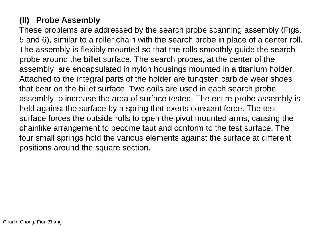
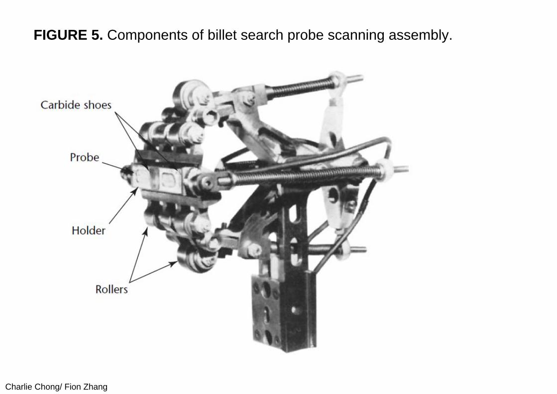
(II) Probe AssemblyThese problems are addressed by the search probe scanning assembly (Figs. 5 and 6), similar to a roller chain with the search probe in place of a center roll. The assembly is flexibly mounted so that the rolls smoothly guide the search probe around the billet surface. The search probes, at the center of the assembly, are encapsulated in nylon housings mounted in a titanium holder. Attached to the integral parts of the holder are tungsten carbide wear shoes that bear on the billet surface. Two coils are used in each search probe assembly to increase the area of surface tested. The entire probe assembly is held against the surface by a spring that exerts constant force. The test surface forces the outside rolls to open the pivot mounted arms, causing the chainlike arrangement to become taut and conform to the test surface. The four small springs hold the various elements against the surface at different positions around the square section.
Charlie Chong/ Fion Zhang
Most of the assembly is constructed from a titanium alloy selected for high strength and lightness. Weight must be minimized because centrifugal forces resulting from rotation and inertia tend to lift the assembly from the billet surface. The high strength of this material permits the assembly to withstand forces resulting from surface roughness and the directional changes necessary during testing. The rolls are tungsten carbide for maximum wear resistance and use bearings but require no lubrication. The dimensions of the probe assembly components affect the instantaneous velocity of the probe relative to the billet surface. The most significant dimensions are the spacing between the rolls, the diameter of the rolls and the distance of the probe pivot from its contact surface.
Charlie Chong/ Fion Zhang
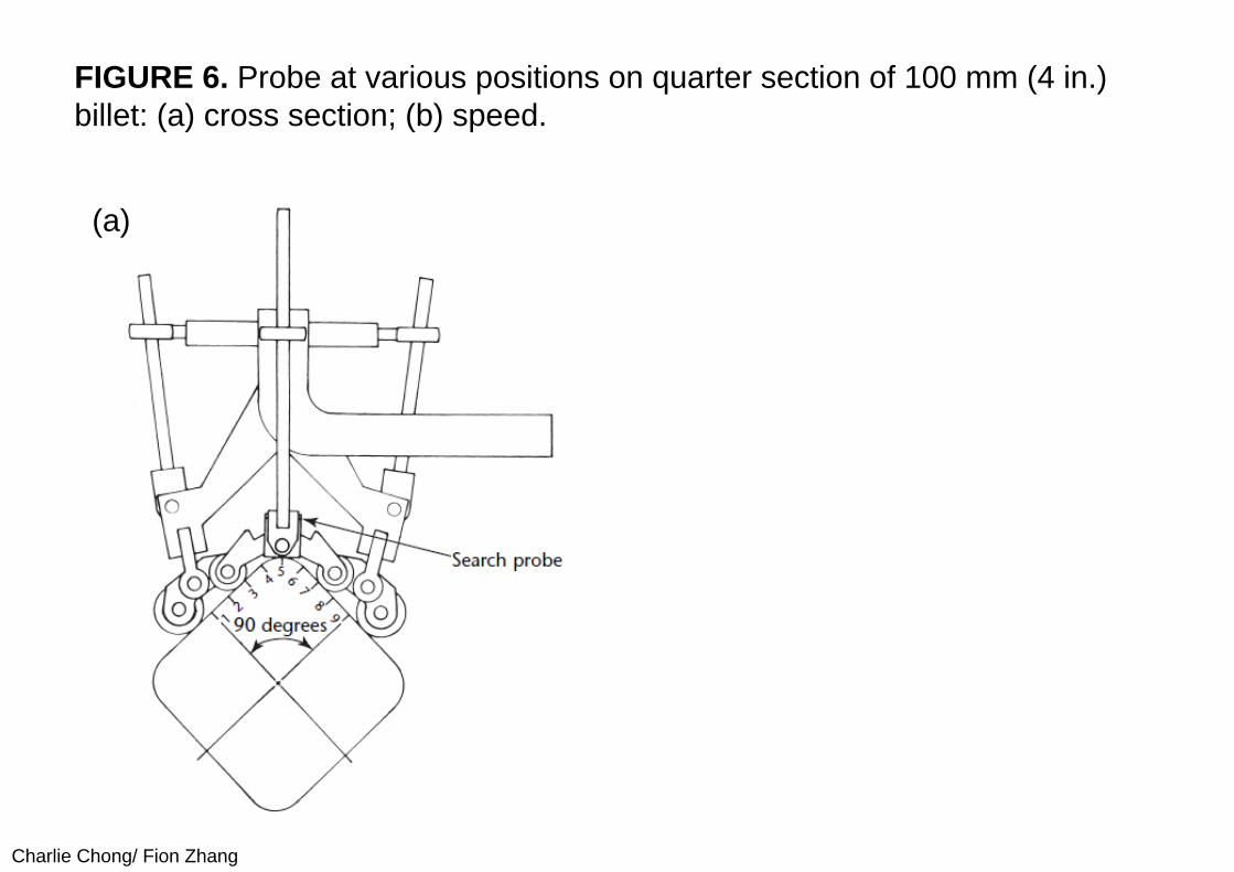
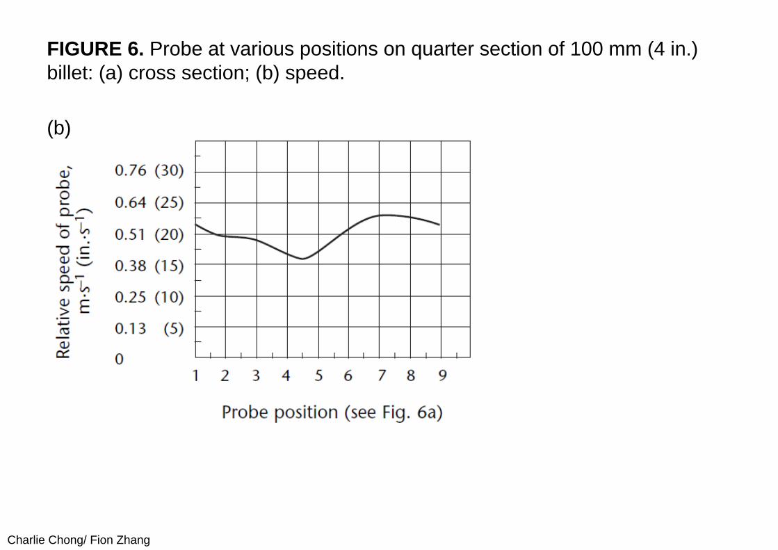
Figure 6 shows the relative speed of the probe at different positions on a quarter section of a billet with a 0.1 m (4 in.) square cross section. The element shape for this assembly gives the probe a velocity that is maximum on the flat part of the surface, where bounce is least likely, and minimum at the corner, where the coil has the greatest tendency to leave the surface. The speed fluctuates smoothly within the allowable testing range as the probe assembly is rotated around a square billet. The probe assembly dimensions are optimized for 102 and 127 mm (4 and 5 in.) billets but this same assembly can test a greater range.
Charlie Chong/ Fion Zhang
FIGURE 5. Components of billet search probe scanning assembly.
Charlie Chong/ Fion Zhang
FIGURE 6. Probe at various positions on quarter section of 100 mm (4 in.) billet: (a) cross section; (b) speed.
(a)
Charlie Chong/ Fion Zhang
FIGURE 6. Probe at various positions on quarter section of 100 mm (4 in.) billet: (a) cross section; (b) speed.
(b)
Charlie Chong/ Fion Zhang
(III) Discontinuity Marking SystemA marking system is selected that consists of spray markers, an air compressor, a paint reservoir and valves to direct paint to the billets. The spray markers and two retractable search assemblies are attached to pivot arms on a rotating face plate. The face plate in turn is attached to a rotating, open ended drum through which the billet passes. The spray markers are spaced to mark the exact location of the seam anywhere around the billet periphery. The other components of the marking system are attached to the exit end of the drum and also rotate. Electrical energy is transmitted by means of slip rings to the search probes, to the solenoid valves for the marking system and to the compressor.
Charlie Chong/ Fion Zhang
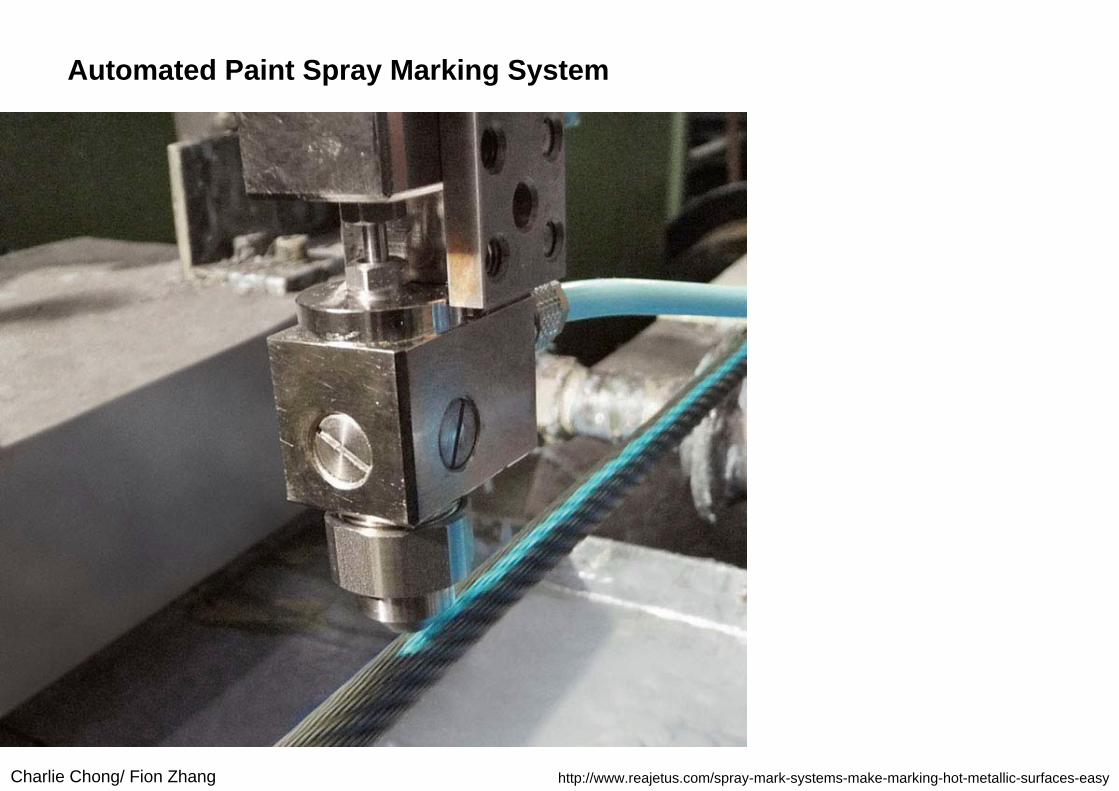
Automated Paint Spray Marking System
http://www.reajetus.com/spray-mark-systems-make-marking-hot-metallic-surfaces-easy
Charlie Chong/ Fion Zhang
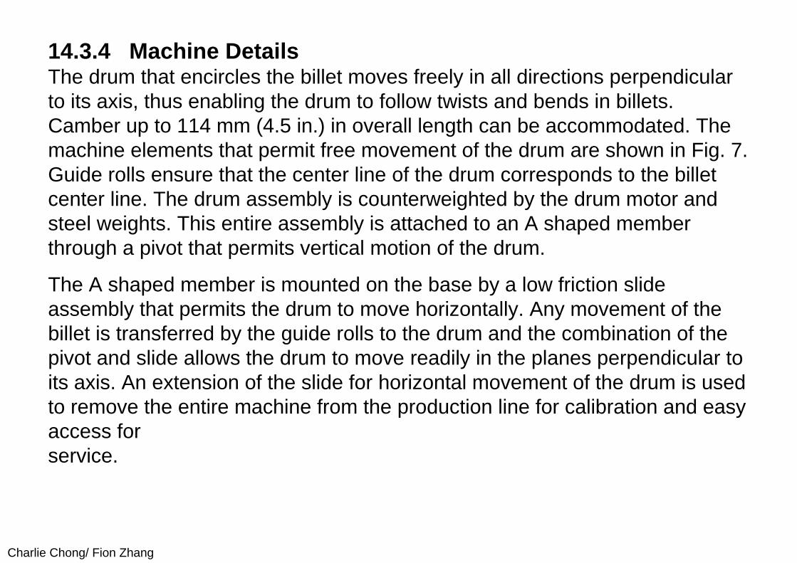
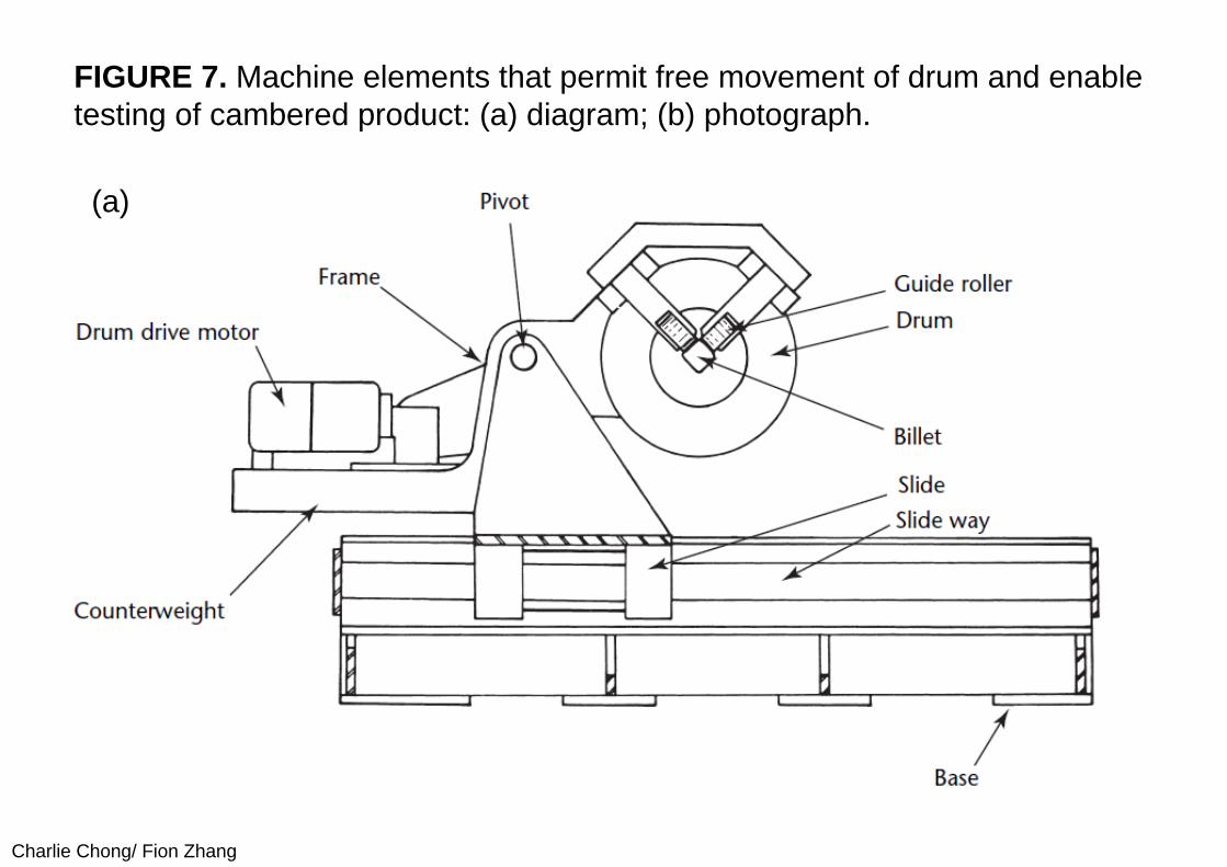
14.3.4 Machine DetailsThe drum that encircles the billet moves freely in all directions perpendicular to its axis, thus enabling the drum to follow twists and bends in billets. Camber up to 114 mm (4.5 in.) in overall length can be accommodated. The machine elements that permit free movement of the drum are shown in Fig. 7. Guide rolls ensure that the center line of the drum corresponds to the billet center line. The drum assembly is counterweighted by the drum motor and steel weights. This entire assembly is attached to an A shaped member through a pivot that permits vertical motion of the drum.
The A shaped member is mounted on the base by a low friction slide assembly that permits the drum to move horizontally. Any movement of the billet is transferred by the guide rolls to the drum and the combination of the pivot and slide allows the drum to move readily in the planes perpendicular to its axis. An extension of the slide for horizontal movement of the drum is used to remove the entire machine from the production line for calibration and easy access for service.
Charlie Chong/ Fion Zhang
FIGURE 7. Machine elements that permit free movement of drum and enable testing of cambered product: (a) diagram; (b) photograph.
(a)
Charlie Chong/ Fion Zhang
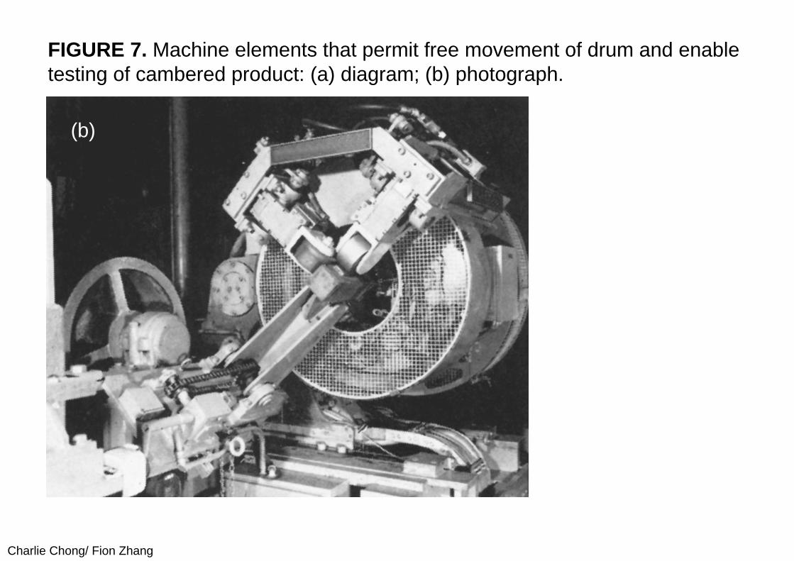
FIGURE 7. Machine elements that permit free movement of drum and enable testing of cambered product: (a) diagram; (b) photograph.
(b)
Charlie Chong/ Fion Zhang
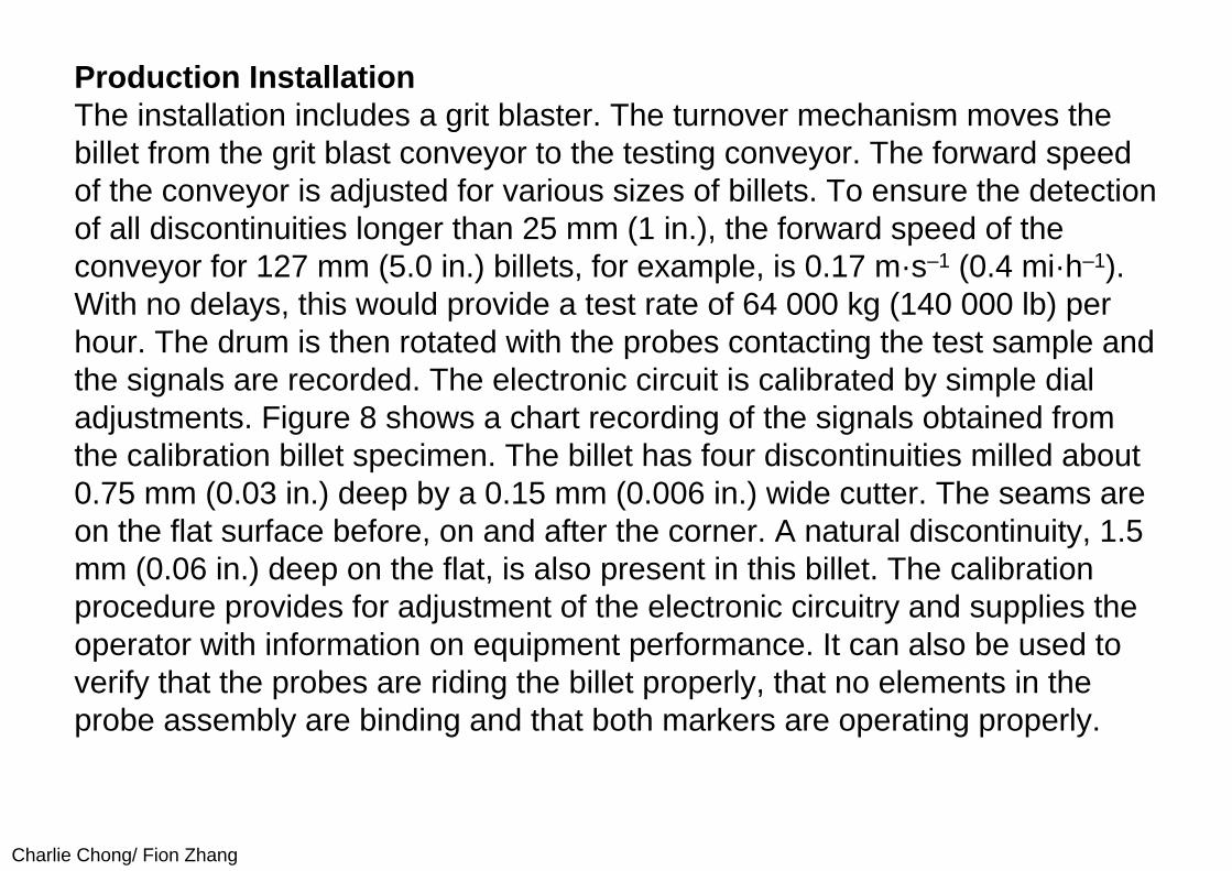
Production InstallationThe installation includes a grit blaster. The turnover mechanism moves the billet from the grit blast conveyor to the testing conveyor. The forward speed of the conveyor is adjusted for various sizes of billets. To ensure the detection of all discontinuities longer than 25 mm (1 in.), the forward speed of the conveyor for 127 mm (5.0 in.) billets, for example, is 0.17 m·s–1 (0.4 mi·h–1). With no delays, this would provide a test rate of 64 000 kg (140 000 lb) per hour. The drum is then rotated with the probes contacting the test sample and the signals are recorded. The electronic circuit is calibrated by simple dial adjustments. Figure 8 shows a chart recording of the signals obtained from the calibration billet specimen. The billet has four discontinuities milled about 0.75 mm (0.03 in.) deep by a 0.15 mm (0.006 in.) wide cutter. The seams are on the flat surface before, on and after the corner. A natural discontinuity, 1.5 mm (0.06 in.) deep on the flat, is also present in this billet. The calibration procedure provides for adjustment of the electronic circuitry and supplies the operator with information on equipment performance. It can also be used to verify that the probes are riding the billet properly, that no elements in the probe assembly are binding and that both markers are operating properly.
Charlie Chong/ Fion Zhang
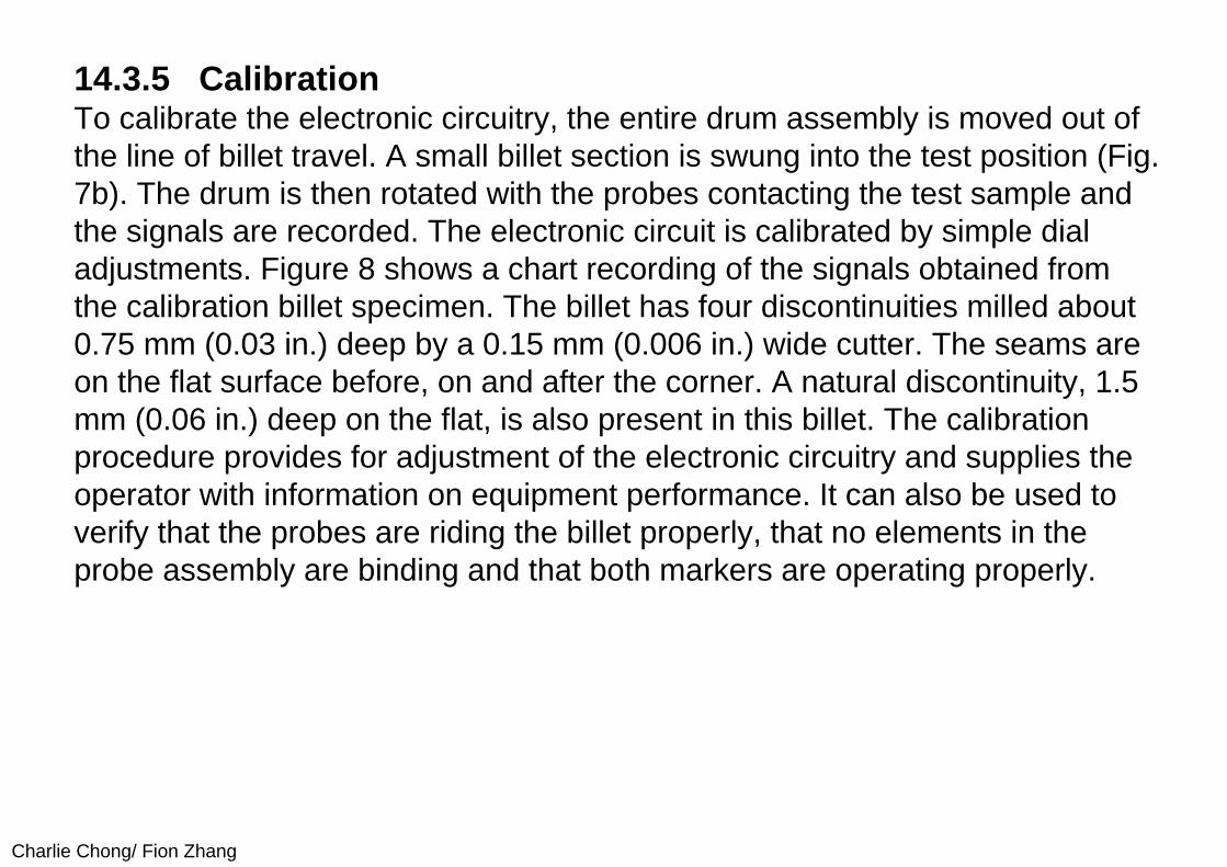
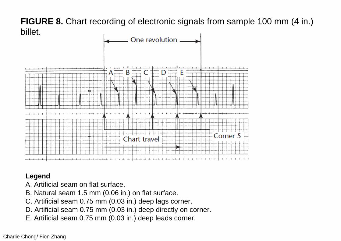
14.3.5 CalibrationTo calibrate the electronic circuitry, the entire drum assembly is moved out of the line of billet travel. A small billet section is swung into the test position (Fig. 7b). The drum is then rotated with the probes contacting the test sample and the signals are recorded. The electronic circuit is calibrated by simple dial adjustments. Figure 8 shows a chart recording of the signals obtained from the calibration billet specimen. The billet has four discontinuities milled about 0.75 mm (0.03 in.) deep by a 0.15 mm (0.006 in.) wide cutter. The seams are on the flat surface before, on and after the corner. A natural discontinuity, 1.5 mm (0.06 in.) deep on the flat, is also present in this billet. The calibration procedure provides for adjustment of the electronic circuitry and supplies the operator with information on equipment performance. It can also be used to verify that the probes are riding the billet properly, that no elements in the probe assembly are binding and that both markers are operating properly.
Charlie Chong/ Fion Zhang
FIGURE 8. Chart recording of electronic signals from sample 100 mm (4 in.)billet.
LegendA. Artificial seam on flat surface.B. Natural seam 1.5 mm (0.06 in.) on flat surface.C. Artificial seam 0.75 mm (0.03 in.) deep lags corner.D. Artificial seam 0.75 mm (0.03 in.) deep directly on corner.E. Artificial seam 0.75 mm (0.03 in.) deep leads corner.

Charlie Chong/ Fion Zhang
14.4 PART 4. Rotating Machine to Test Hot Steel Rods and Wires
14.4.1 Integration of Test before CoilingWires and bars are usually coiled immediately after they are hot rolled. When discontinuity detection is performed on cold products, they must be uncoiled for testing. If discontinuity detection can be accomplished during the rolling process, while wires or bars are still hot, costs can be reduced by saving electric power and by omitting the uncoiling process. Eddy current testing using an encircling coil has been applied to hot rolling of bars. Steel mills use encircling coil eddy current systems to test hot wires. Generally, encircling coils in a differential configuration can detect short discontinuities such as scabs and roll marks. It is, however, difficult to detect harmful longitudinal discontinuities such as seams and cracks.
Charlie Chong/ Fion Zhang
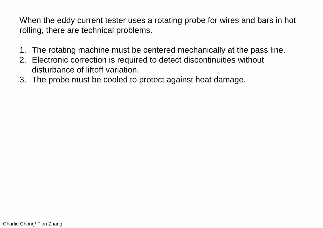
When the eddy current tester uses a rotating probe for wires and bars in hotrolling, there are technical problems.
1. The rotating machine must be centered mechanically at the pass line. 2. Electronic correction is required to detect discontinuities without
disturbance of liftoff variation. 3. The probe must be cooled to protect against heat damage.
Charlie Chong/ Fion Zhang
14.4.2 Testing MachineTo apply the rotating probe technique to hot wires and bars, it is important to develop the techniques to suppress the liftoff variation and correct discontinuity signal amplitude by measurement of liftoff variation. The liftoff variation is caused by wobble of wires or bars and by difference of centering between the rotating test machine and the pass line. Components have been developed for the technique. An electronic controller can eliminate the signal caused by the residual liftoff variation and correct the corresponding discontinuity signal. The influence of liftoff variation is also minimized by several means.
Charlie Chong/ Fion Zhang
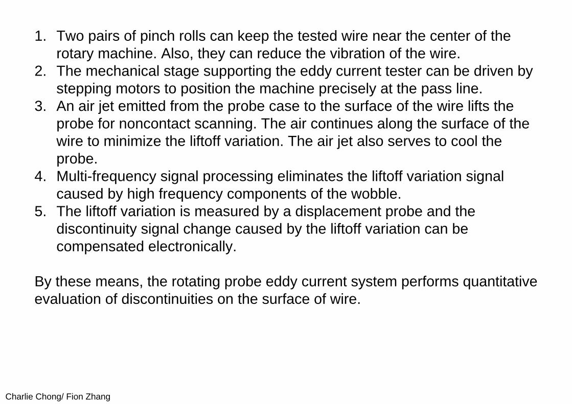
1. Two pairs of pinch rolls can keep the tested wire near the center of the rotary machine. Also, they can reduce the vibration of the wire.
2. The mechanical stage supporting the eddy current tester can be driven by stepping motors to position the machine precisely at the pass line.
3. An air jet emitted from the probe case to the surface of the wire lifts the probe for noncontact scanning. The air continues along the surface of the wire to minimize the liftoff variation. The air jet also serves to cool the probe.
4. Multi-frequency signal processing eliminates the liftoff variation signal caused by high frequency components of the wobble.
5. The liftoff variation is measured by a displacement probe and the discontinuity signal change caused by the liftoff variation can be compensated electronically.
By these means, the rotating probe eddy current system performs quantitative evaluation of discontinuities on the surface of wire.
Charlie Chong/ Fion Zhang
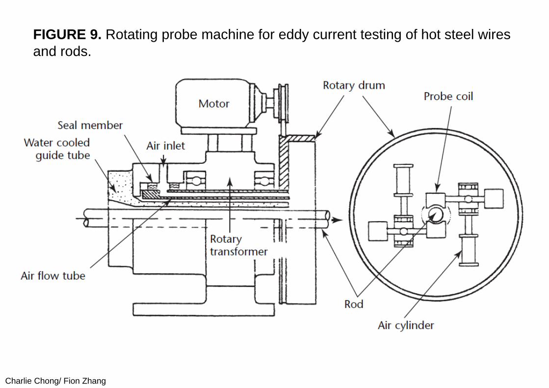
(I) Rotating Probe MachineFigure 9 schematically shows the eddy current testing machine with rotating probes. It consists of a rotary drum that has two sensor holders and actuators for sensor holders, a cylindrical housing and a motor that drives the rotary drum. The cylindrical housing has a rotary transformer, an air flow tube of duplex steel and a water cooled guide tube. The rotary drum is mounted on the downstream side of the housing. The motor can drive the rotary drum at the maximum rotation speed of 16.7 cycles per second (1000 rotations per minute). Within the rotary drum, the sensor holders are mounted with probes and air cylinders for retracting the probe. The probe is moved away from the center of the rotary drum by the air cylinder to keep the probe from rubbing against the top or bottom of the material. The mechanism for retracting the probe successfully operates at up to 16.7 cycles per second (1000 rotations per minute) even though centrifugal force acts against the mechanism.
Charlie Chong/ Fion Zhang
FIGURE 9. Rotating probe machine for eddy current testing of hot steel wires and rods.
Charlie Chong/ Fion Zhang
The air flow tube is made of duplex steel and comprises an inner tube and an outer sleeve. The air conduit extends into the rotary drum at the downstream side end. To supply compressed air to the rotary drum, sealing members are fitted between rotor and stator as shown in Fig. 9. The compressed air has three functions:
(1) noncontact scanning using air jets, (2) cooling the probe coil and (3) driving the air cylinder.
The air cylinder is controlled by solenoid valves mounted on the rotary drum. The water cooled guide tube is fitted into the air tube. The guide tube protects the rotary transformer and bearings against heat damage. The signals from the non contacting probe coil are sent or received by the rotary transformer.
Charlie Chong/ Fion Zhang
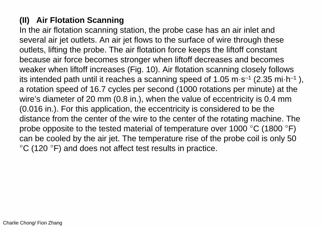
(II) Air Flotation ScanningIn the air flotation scanning station, the probe case has an air inlet and several air jet outlets. An air jet flows to the surface of wire through these outlets, lifting the probe. The air flotation force keeps the liftoff constant because air force becomes stronger when liftoff decreases and becomes weaker when liftoff increases (Fig. 10). Air flotation scanning closely follows its intended path until it reaches a scanning speed of 1.05 m·s–1 (2.35 mi·h–1 ), a rotation speed of 16.7 cycles per second (1000 rotations per minute) at the wire’s diameter of 20 mm (0.8 in.), when the value of eccentricity is 0.4 mm (0.016 in.). For this application, the eccentricity is considered to be the distance from the center of the wire to the center of the rotating machine. The probe opposite to the tested material of temperature over 1000 °C (1800 °F) can be cooled by the air jet. The temperature rise of the probe coil is only 50 °C (120 °F) and does not affect test results in practice.
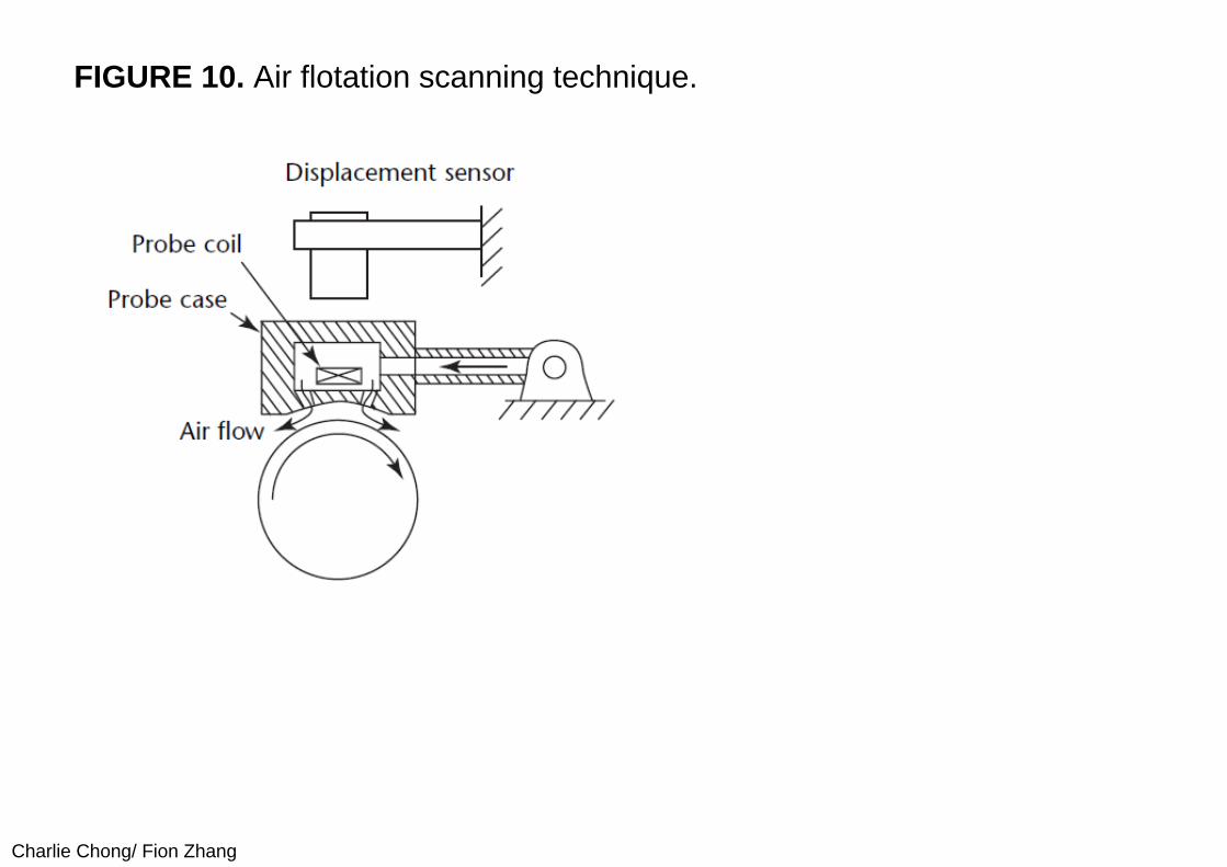
Charlie Chong/ Fion Zhang
FIGURE 10. Air flotation scanning technique.
Charlie Chong/ Fion Zhang
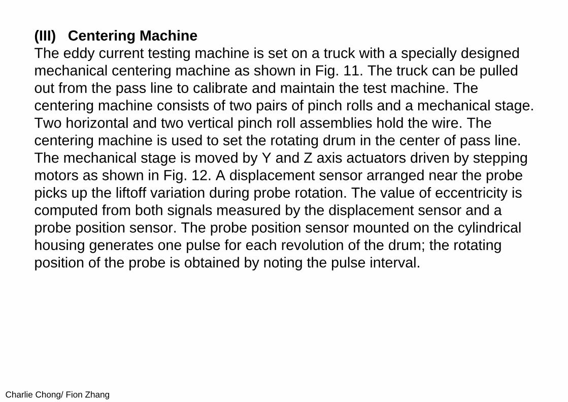
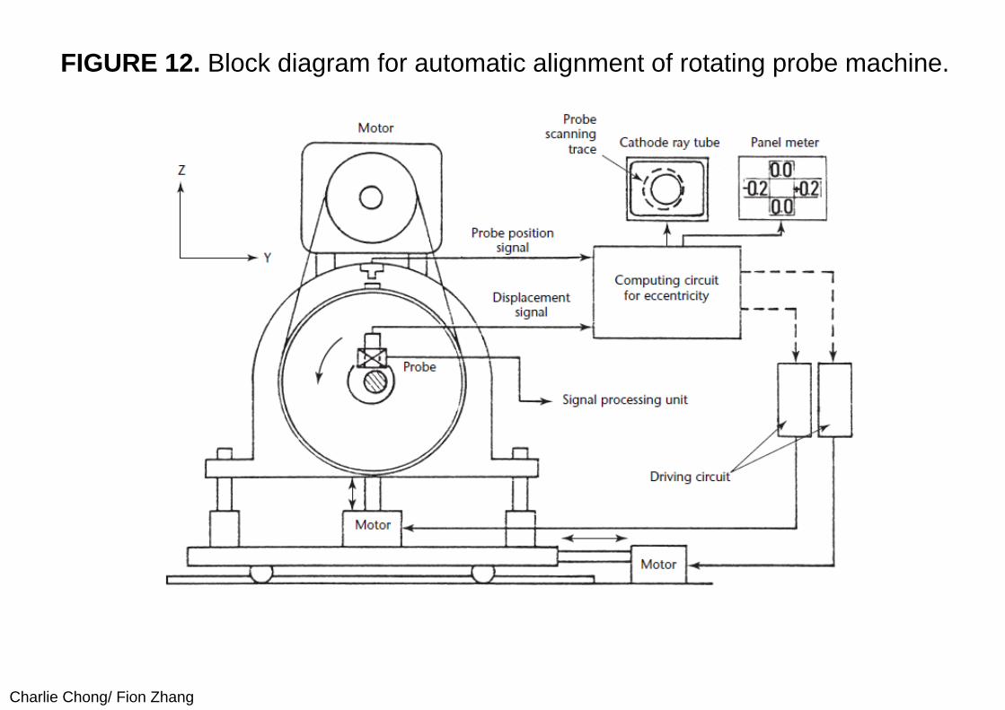
(III) Centering MachineThe eddy current testing machine is set on a truck with a specially designed mechanical centering machine as shown in Fig. 11. The truck can be pulled out from the pass line to calibrate and maintain the test machine. The centering machine consists of two pairs of pinch rolls and a mechanical stage. Two horizontal and two vertical pinch roll assemblies hold the wire. The centering machine is used to set the rotating drum in the center of pass line. The mechanical stage is moved by Y and Z axis actuators driven by stepping motors as shown in Fig. 12. A displacement sensor arranged near the probe picks up the liftoff variation during probe rotation. The value of eccentricity is computed from both signals measured by the displacement sensor and a probe position sensor. The probe position sensor mounted on the cylindrical housing generates one pulse for each revolution of the drum; the rotating position of the probe is obtained by noting the pulse interval.
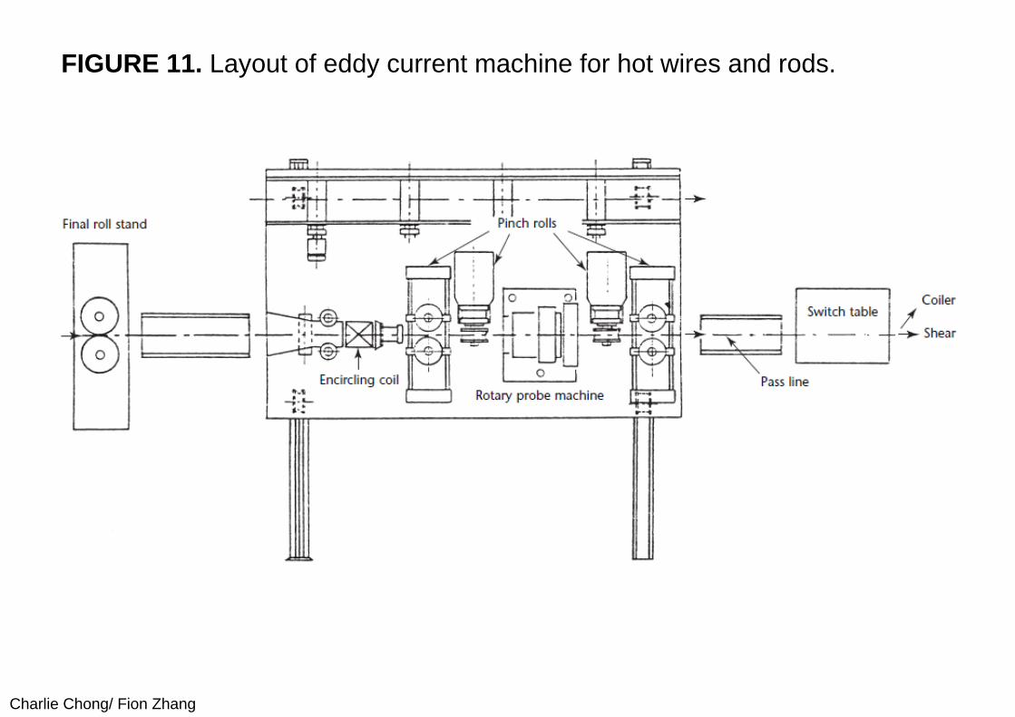
Charlie Chong/ Fion Zhang
FIGURE 11. Layout of eddy current machine for hot wires and rods.
Charlie Chong/ Fion Zhang
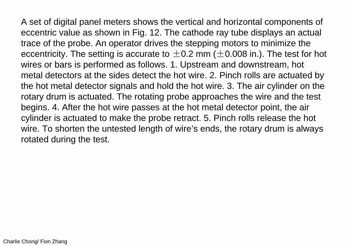
A set of digital panel meters shows the vertical and horizontal components of eccentric value as shown in Fig. 12. The cathode ray tube displays an actual trace of the probe. An operator drives the stepping motors to minimize the eccentricity. The setting is accurate to ±0.2 mm (±0.008 in.). The test for hot wires or bars is performed as follows. 1. Upstream and downstream, hot metal detectors at the sides detect the hot wire. 2. Pinch rolls are actuated by the hot metal detector signals and hold the hot wire. 3. The air cylinder on the rotary drum is actuated. The rotating probe approaches the wire and the test begins. 4. After the hot wire passes at the hot metal detector point, the air cylinder is actuated to make the probe retract. 5. Pinch rolls release the hot wire. To shorten the untested length of wire’s ends, the rotary drum is always rotated during the test.
Charlie Chong/ Fion Zhang
FIGURE 12. Block diagram for automatic alignment of rotating probe machine.
Charlie Chong/ Fion Zhang
14.4.3 Signal Processing Multi-frequency Signal ProcessingPhase analysis and frequency analysis are used to suppress the liftoff variation signal. Because the phase angle difference between thediscontinuity signal and the liftoff variation signal in hot steel testing is usually slight, such as 0.18 to 0.35 mrad (10 to 20 deg.), it is difficult to discriminate the liftoff variation by phase analysis. On the other hand, the frequency analysis technique serves to suppress an undesirable signal by means of a frequency difference between the undesirable signal and the discontinuity signal.
Because the liftoff variation caused by the vibration of wire has frequency components similar to those of the discontinuity signal, however, this technique cannot distinguish the signals. The wobble of wire is caused by vibrations from a roll stand or a coiling machine. The air floating sensors cannot follow the surface of wire whose vibration frequency is over 20 cycles per second. To make it possible to suppress the signal caused by this vibration and to detect a discontinuity with higher ratio of signal to noise, the multifrequency eddy current technique is applied. Multifrequency eddy current testing of hot wires with encircling and probe coils has been reported.
Charlie Chong/ Fion Zhang
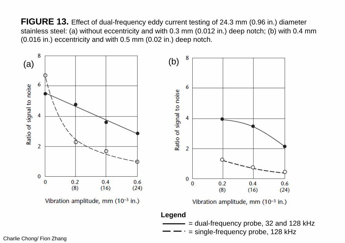
(I) Single-Frequency versus Dual-Frequency TestingThe single-frequency and dual-frequency techniques have been compared for detectability by using an austenitic stainless steel bar with artificial discontinuities. Electromagnetic properties of the stainless bar are similar to those of hot steel over the magnetic curie temperature. The liftoff variation of the tested bar is given by the vibrator. The relation between the vibration amplitude of the tested bar and detectability of artificial discontinuities whose depth is 0.3 mm (0.012 in.) is shown in Fig. 13a. The data are obtained under the condition without eccentricity. For detecting artificial discontinuities, the single-frequency technique is better than the dual-frequency technique when there is no eccentricity and no vibration. However, detectability with the single-frequency technique decreases markedly with the increase of vibration amplitude. On the other hand, discontinuity detectability decreases slowly with the dual-frequency technique. The dual-frequency technique is superior to the single-frequency technique when there is vibration. Where the eccentricity is greater than the vibration of the tested bar, the difference in detectability between the two techniques becomes even greater, as shown in Fig. 13b. Both vibration and eccentricity are present in the testing of hot wires, making the dual-frequency technique very efficient for discontinuity detection.
Charlie Chong/ Fion Zhang
FIGURE 13. Effect of dual-frequency eddy current testing of 24.3 mm (0.96 in.) diameter stainless steel: (a) without eccentricity and with 0.3 mm (0.012 in.) deep notch; (b) with 0.4 mm (0.016 in.) eccentricity and with 0.5 mm (0.02 in.) deep notch.
Legend= dual-frequency probe, 32 and 128 kHz= single-frequency probe, 128 kHz
(a) (b)
Charlie Chong/ Fion Zhang
(II) Signal Processing for Liftoff CompensationThe liftoff variation changes the amplitude of the discontinuity signal itself. When liftoff varies, it is impractical to measure a discontinuity size by the amplitude of discontinuity signals. In such cases, the liftoff compensation circuit can be adopted.
The compensation circuit consists of a function converter and a calculator. The liftoff signal is converted to a compensated value by the function converter. The outputs of the function converter and discontinuity signal are multiplied by the calculator and provide a signal in proportion to discontinuity depth. For example, when the liftoff varies from 0.7 mm to 1.3 mm (0.03 to 0.05 in.), the signal amplitude nearly doubles. This circuit ensures that signal amplitude varies by less than ±10 percent.
Charlie Chong/ Fion Zhang
14.5 PART 5. Seam Testing in Hot Steel Rods 14.5.1 Surface Testing in RodsSurface discontinuity testing is essential in the quality assurance of iron and steel products. In many mills, quality control of hot rolled rods is provided through eddy current and magnetic flux leak testing carried out after the rolling, shearing and cooling processes. If the test is made during hot rolling, information about surface quality could be rapidly fed back to the rolling process, thus minimizing the quantity of surface discontinuities in future products.
To achieve this, the encircling coil technique has been put into practice. However, the orientation of encircling coils is unsuited for detection of long discontinuities, such as seams.(?)
Charlie Chong/ Fion Zhang
14.5.2 Rotary Probe System FeaturesThe rotary probe eddy current technique has been widely used for cold rods and is described here for the detection of long surface discontinuities during the hot rolling of iron and steel rods. The probe has been modified for the temperature of the rods. Rotary probe techniques, when installed immediately after the finishing stand in the rolling process, are suited for detecting seams with depths over 0.3 mm (0.012 in.). In addition to functions needed for cold rods, the rotary probe discontinuity detector must perform the following functions for hot rods:
(1) provide heat resistance for discontinuity detection in high temperature materials,
(2) compensate for the vibration of the rod under hot rolling and (3) provide for probe retraction to protect the probe from the deformed ends of
the hot rod.
Charlie Chong/ Fion Zhang
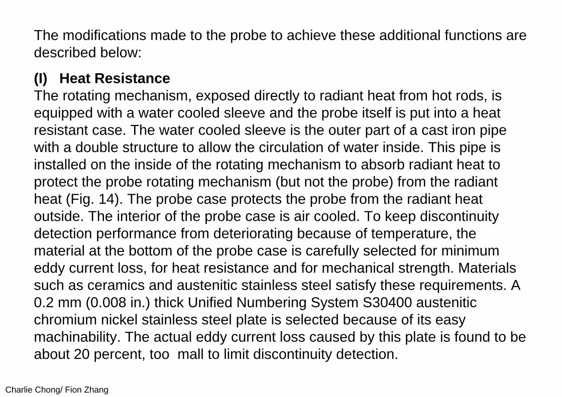
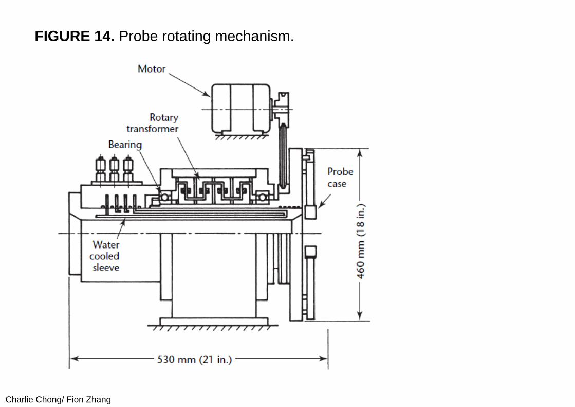
The modifications made to the probe to achieve these additional functions are described below:
(I) Heat ResistanceThe rotating mechanism, exposed directly to radiant heat from hot rods, is equipped with a water cooled sleeve and the probe itself is put into a heat resistant case. The water cooled sleeve is the outer part of a cast iron pipe with a double structure to allow the circulation of water inside. This pipe is installed on the inside of the rotating mechanism to absorb radiant heat to protect the probe rotating mechanism (but not the probe) from the radiant heat (Fig. 14). The probe case protects the probe from the radiant heat outside. The interior of the probe case is air cooled. To keep discontinuity detection performance from deteriorating because of temperature, the material at the bottom of the probe case is carefully selected for minimum eddy current loss, for heat resistance and for mechanical strength. Materials such as ceramics and austenitic stainless steel satisfy these requirements. A 0.2 mm (0.008 in.) thick Unified Numbering System S30400 austenitic chromium nickel stainless steel plate is selected because of its easy machinability. The actual eddy current loss caused by this plate is found to be about 20 percent, too mall to limit discontinuity detection.
Charlie Chong/ Fion Zhang
FIGURE 14. Probe rotating mechanism.
Charlie Chong/ Fion Zhang
(II) Compensation for Rod VibrationHigh speed rolling produces large vibrations of the rods. Measures are required to compensate for vibratory effects. The vibrations could be either high or low frequency, calling for different countermeasures. High frequency vibration causes fluctuation in the liftoff, thus deteriorating the ratio of signal to noise. On the other hand, the frequency of the discontinuity signal is proportional to the probe rotation speed. If the discontinuity signal is of much higher frequency than the liftoff fluctuation noise, it may be distinguished by means of a high pass filter. It is therefore necessary to increase the probe rotation speed as a measure against vibration. The vibration frequency of rods under hot rolling is found to be about 10 cycles per second (600 rotations per minute). Hence, probe rotation is set to three times the vibration frequency, 30 cycles per second (1800 rotations per minute).
Charlie Chong/ Fion Zhang
The low frequency vibration refers to the fluctuation of the passing position of the rods (pass line fluctuation), a phenomenon that rarely occurs at low speed. When this does occur, the probe rotational orbit becomes eccentric with the rods, causing liftoff fluctuation as the probe rotates even if the rod itself does not rotate. Being proportional to the probe rotational speed, this noise cannot be distinguished from the discontinuity signal even if the rotational speed of the probe is increased.
To eliminate this noise, a servo mechanism is added to make the probe rotating mechanism follow the pass line fluctuation. Liftoff compensation is desirable and may be provided by an optical or other sensor designed for the application.
Charlie Chong/ Fion Zhang
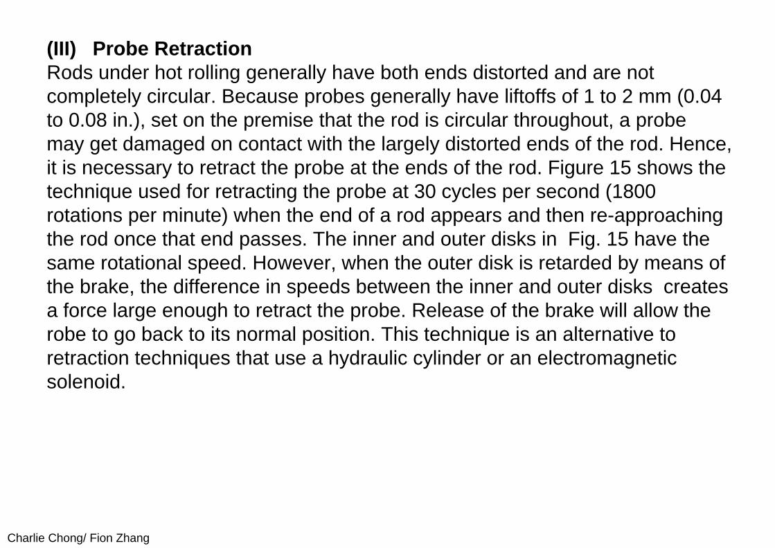
(III) Probe RetractionRods under hot rolling generally have both ends distorted and are not completely circular. Because probes generally have liftoffs of 1 to 2 mm (0.04 to 0.08 in.), set on the premise that the rod is circular throughout, a probe may get damaged on contact with the largely distorted ends of the rod. Hence, it is necessary to retract the probe at the ends of the rod. Figure 15 shows the technique used for retracting the probe at 30 cycles per second (1800 rotations per minute) when the end of a rod appears and then re-approaching the rod once that end passes. The inner and outer disks in Fig. 15 have the same rotational speed. However, when the outer disk is retarded by means of the brake, the difference in speeds between the inner and outer disks creates a force large enough to retract the probe. Release of the brake will allow the robe to go back to its normal position. This technique is an alternative to retraction techniques that use a hydraulic cylinder or an electromagnetic solenoid.
Charlie Chong/ Fion Zhang
FIGURE 15. Probe retracting technique.
Charlie Chong/ Fion Zhang
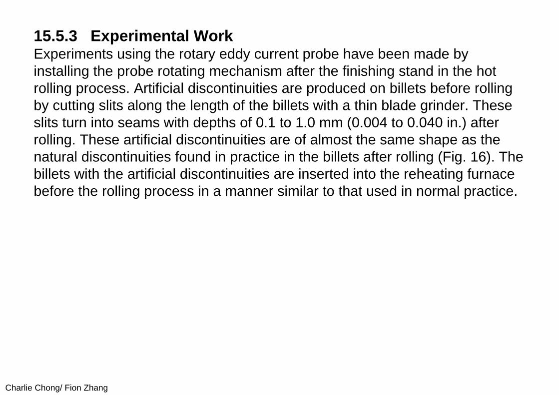
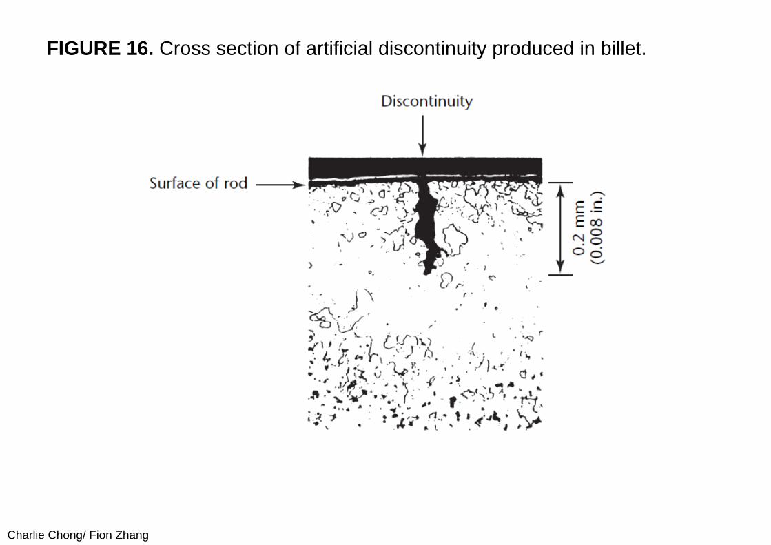
15.5.3 Experimental WorkExperiments using the rotary eddy current probe have been made by installing the probe rotating mechanism after the finishing stand in the hot rolling process. Artificial discontinuities are produced on billets before rolling by cutting slits along the length of the billets with a thin blade grinder. These slits turn into seams with depths of 0.1 to 1.0 mm (0.004 to 0.040 in.) after rolling. These artificial discontinuities are of almost the same shape as the natural discontinuities found in practice in the billets after rolling (Fig. 16). The billets with the artificial discontinuities are inserted into the reheating furnace before the rolling process in a manner similar to that used in normal practice.
Charlie Chong/ Fion Zhang
FIGURE 16. Cross section of artificial discontinuity produced in billet.
Charlie Chong/ Fion Zhang
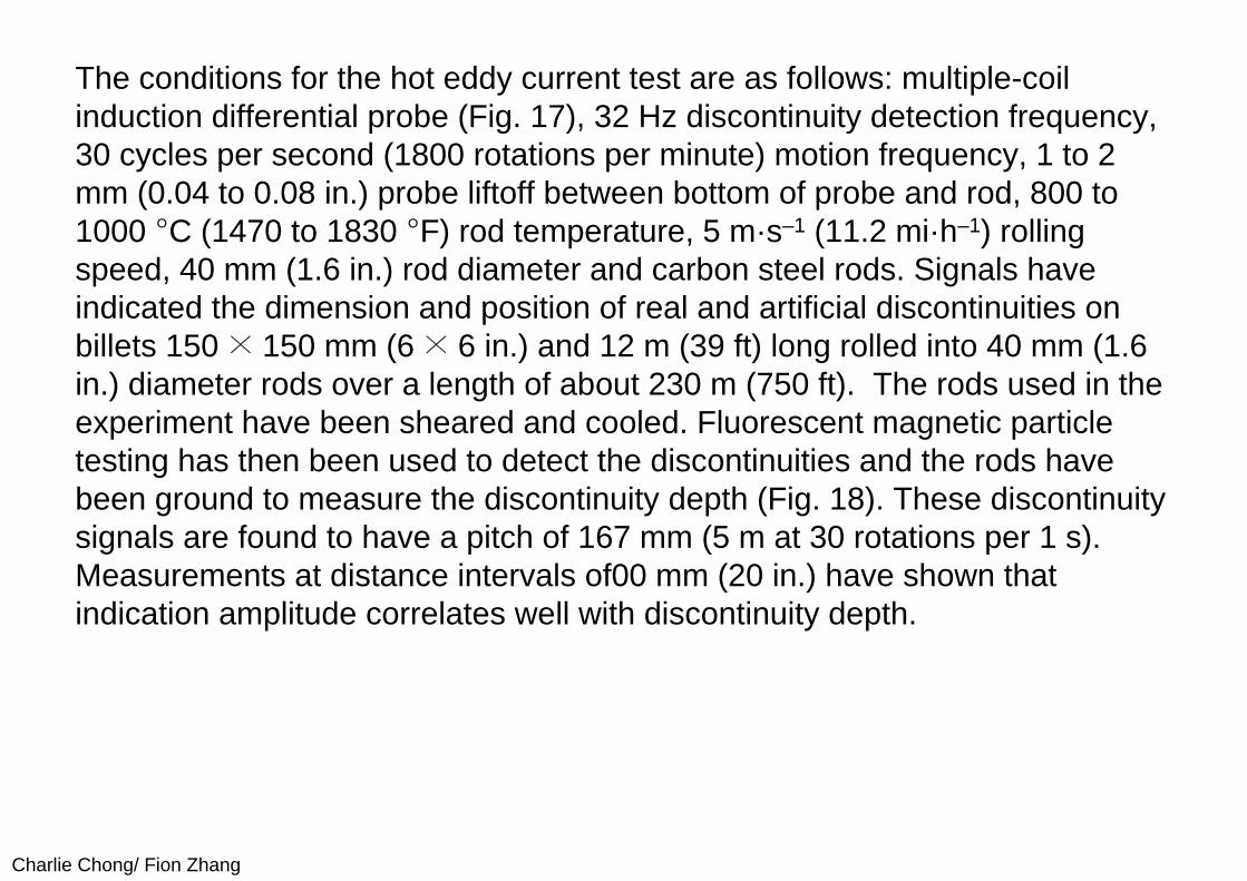
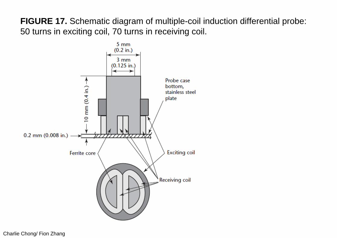
The conditions for the hot eddy current test are as follows: multiple-coil induction differential probe (Fig. 17), 32 Hz discontinuity detection frequency, 30 cycles per second (1800 rotations per minute) motion frequency, 1 to 2 mm (0.04 to 0.08 in.) probe liftoff between bottom of probe and rod, 800 to 1000 °C (1470 to 1830 °F) rod temperature, 5 m·s–1 (11.2 mi·h–1) rolling speed, 40 mm (1.6 in.) rod diameter and carbon steel rods. Signals have indicated the dimension and position of real and artificial discontinuities on billets 150 × 150 mm (6 × 6 in.) and 12 m (39 ft) long rolled into 40 mm (1.6 in.) diameter rods over a length of about 230 m (750 ft). The rods used in the experiment have been sheared and cooled. Fluorescent magnetic particle testing has then been used to detect the discontinuities and the rods have been ground to measure the discontinuity depth (Fig. 18). These discontinuity signals are found to have a pitch of 167 mm (5 m at 30 rotations per 1 s). Measurements at distance intervals of00 mm (20 in.) have shown that indication amplitude correlates well with discontinuity depth.
Charlie Chong/ Fion Zhang
FIGURE 17. Schematic diagram of multiple-coil induction differential probe: 50 turns in exciting coil, 70 turns in receiving coil.
Charlie Chong/ Fion Zhang
FIGURE 18. Discontinuity depths and signals in sections of steel rod made from billets that had 3 mm (0.12 in.) wide artificial discontinuities machined into them before rolling: (a) 4 mm (0.16 in.) prerolling depth; (b) 3 mm (0.12 in.) prerolling depth; (c) 5 mm (0.20 in.) prerolling depth.
Charlie Chong/ Fion Zhang
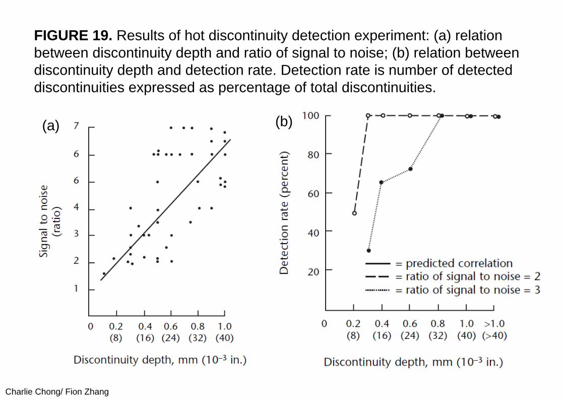
14.5.4 ReliabilityThe variation of the signal-to-noise ratio and the detection rate with the discontinuity depth are shown in Fig. 19. If a discontinuity is considered detectable at a signal-to-noise ratio of 2, the probability of detection for discontinuities over 0.3 mm (0.012 in.) is 100 percent. On the other hand, if a discontinuity is considered detectable only at a signal-to-noise ratio of 3, the probability of detection of discontinuities 0.3 mm (0.012 in.) and deeper drops to an average of 83 percent.
Charlie Chong/ Fion Zhang
FIGURE 19. Results of hot discontinuity detection experiment: (a) relation between discontinuity depth and ratio of signal to noise; (b) relation between discontinuity depth and detection rate. Detection rate is number of detected discontinuities expressed as percentage of total discontinuities.
(a) (b)
Charlie Chong/ Fion Zhang
14.6 PART 6. Online Testing of Hot Metal Products14.6.1 Process Control of Hot Metal RodsQuality control of hot metal is difficult in view of the material’s high temperature and the production environment, which is unsuitable for sensitive electronic measurements. The problem is compounded in single-strand rod mills by the speed of the production line, which reaches 120 m·s–1 (268 mi·h–1).
Eddy current testing is well suited for the quality evaluation of hot rods because of its fundamental characteristics:
(1) measurement without contact, which allows quality control at high temperature and high speed, and (2) the rapid response time of the sensor, which permits quality testing in real time with a suitable computer.
Charlie Chong/ Fion Zhang
(I) Statistical Process ControlA steel coil is normally 5 or 6 km (3 or 4 mi) long and can be as long as 9 km (6 mi), depending on the size of the billet used and the diameter of the rod produced. One particular eddy current technique concentrates on determining a statistical distribution of the discontinuities on the coil length rather than on locating each discontinuity precisely.
There are four main stages of quality control.
1. Discontinuities are detected, located and sized. 2. Discontinuities are counted in each 10 mm (0.4 in.) length. This gives a
count, for example, of 600 000 data over a 6 km (4 mi) coil. 3. These data are gathered in segments or windows of a predetermined
length. 4. A final quality report is based on an algorithm specific to the mill. This
includes an overall quality index and depends on the quality criteria desired. For example, the operator may decide the discontinuity density that must not be exceeded.
Charlie Chong/ Fion Zhang
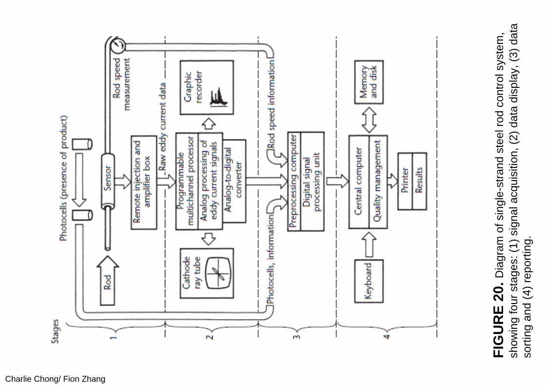
Figure 20 shows the four main stages in the eddy current test.
1. The sensor gathers raw analog data of the eddy current discontinuity detection.
2. The analog signal processing system displays analog discontinuity signal data.
3. The digital preprocessing system sorts the discontinuity signals according to amplitude and location.
4. The results are printed out using software for a final quality report of the coil.
Charlie Chong/ Fion Zhang
FIG
UR
E 20
. Dia
gram
of s
ingl
e-st
rand
ste
el ro
d co
ntro
l sys
tem
, sh
owin
g fo
ur s
tage
s: (1
) sig
nal a
cqui
sitio
n, (2
) dat
a di
spla
y, (3
) dat
a so
rting
and
(4) r
epor
ting.
Charlie Chong/ Fion Zhang
(A) Sensor. The sensor is an encircling coil located just after the finishing stand. Photoelectric cells on either side signal the beginning and end of rods passing through at high speeds. Guides at either end of the sensor feed the rod through the exact center of the coil. Arranged as a self-comparison differential coil, the sensor has separate injection and reception functions. The sensor injection coil is powered by a high frequency current (about 100 kHz) from the programmable multichannel processor (an analog unit, described below), through an injection box near the sensor. The reception coils deliver an eddy current signal immediately as a discontinuity passes through their magnetic fields.
Charlie Chong/ Fion Zhang
(B) Analog Signal Processing. The raw signals are sent to the programmable multichannel system through the amplification box near the injection box and the sensor. Theprogrammable multichannel system is an analog unit that can be controlled remotely. It processes the discontinuity signals, with processes such as filtering, dephasing and expanding. The signals are then (1) displayed in phase and amplitude on a normal cathode ray tube (for checking or adjustment of the system) and (2) presented on a multichannel graphic recorder (one channel per strand). This information gives the rod mill operator an immediate, initial idea of rod quality.
Charlie Chong/ Fion Zhang
(C) Digital Preprocessing. A preprocessing computer receives the product presence and speed signals in addition to data from the programmable multichannel processor. Then, with special software, the preprocessing computer performs data reduction. The eddy current signals are digitized, are integrated for 10 mm (0.4 in.) unit lengths of rod and are sorted according to three amplitude levels, one of which is background noise.
Results. Finally, the preprocessed information is collected by the central processing unit that manages the whole system. This computer produces an analysis report of each window over the entire coil as well as an overall quality index. The report is produced according to a quality program in the computer. The user can select or customize programs according to the quality level desired for the application. Of course, the central processing unit may be hooked up to the central quality management omputer of the rod mill or the plant.
Charlie Chong/ Fion Zhang
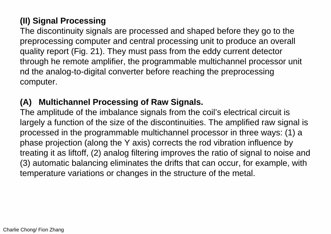
(II) Signal ProcessingThe discontinuity signals are processed and shaped before they go to the preprocessing computer and central processing unit to produce an overall quality report (Fig. 21). They must pass from the eddy current detector through he remote amplifier, the programmable multichannel processor unit nd the analog-to-digital converter before reaching the preprocessing computer.
(A) Multichannel Processing of Raw Signals.The amplitude of the imbalance signals from the coil’s electrical circuit is largely a function of the size of the discontinuities. The amplified raw signal is processed in the programmable multichannel processor in three ways: (1) a phase projection (along the Y axis) corrects the rod vibration influence by treating it as liftoff, (2) analog filtering improves the ratio of signal to noise and (3) automatic balancing eliminates the drifts that can occur, for example, with temperature variations or changes in the structure of the metal.

Charlie Chong/ Fion Zhang
(B) Sampling, Discontinuity Counting and Digitizing. A pulse generator at the rod drive wheel delivers a pulse for every 10 mm (0.4 in.) of the passing rod. This pulse will group the discontinuities detected in each unit length of rod. The programmable multichannel processor counts and memorizes the passing peaks. A 6 km (4 mi) coil, for example, will have 600 000 data after sampling and counting. This information, in the form of analog voltages, is then converted into digital values.
Charlie Chong/ Fion Zhang
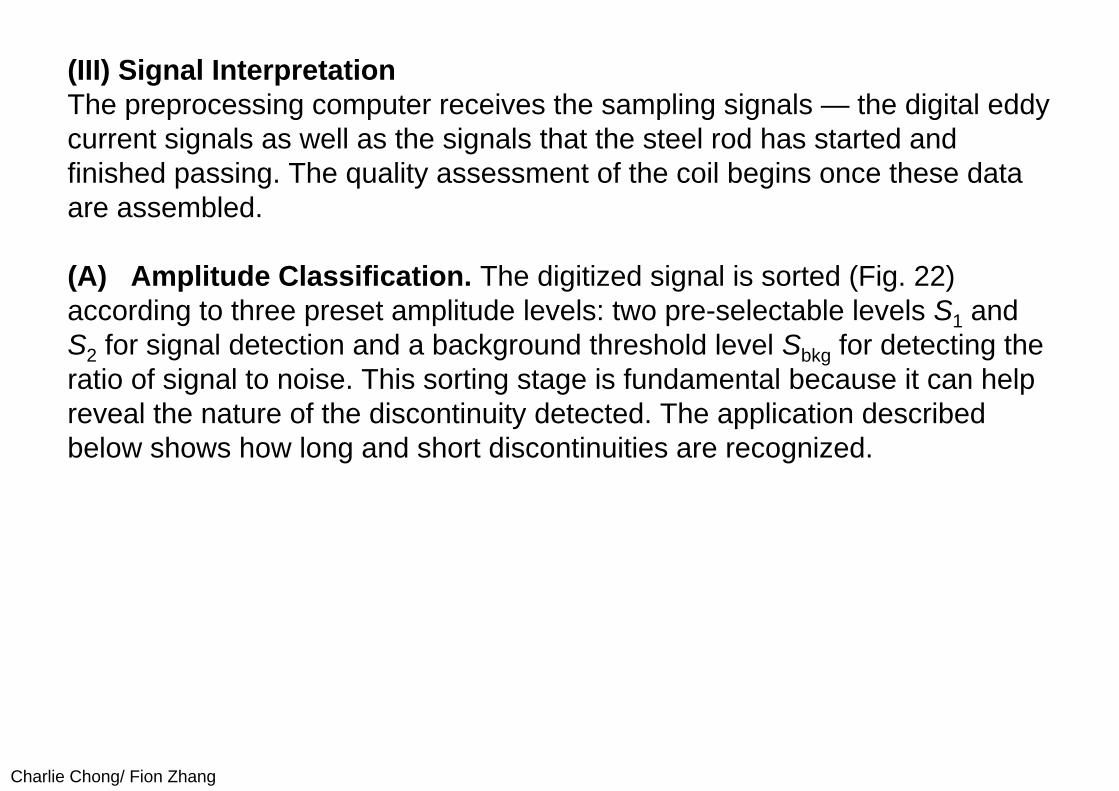
(III) Signal InterpretationThe preprocessing computer receives the sampling signals — the digital eddy current signals as well as the signals that the steel rod has started and finished passing. The quality assessment of the coil begins once these data are assembled.
(A) Amplitude Classification. The digitized signal is sorted (Fig. 22) according to three preset amplitude levels: two pre-selectable levels S1 and S2 for signal detection and a background threshold level Sbkg for detecting the ratio of signal to noise. This sorting stage is fundamental because it can help reveal the nature of the discontinuity detected. The application described below shows how long and short discontinuities are recognized.
Charlie Chong/ Fion Zhang
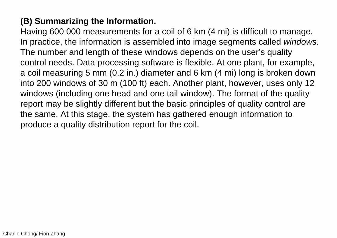
(B) Summarizing the Information. Having 600 000 measurements for a coil of 6 km (4 mi) is difficult to manage. In practice, the information is assembled into image segments called windows. The number and length of these windows depends on the user’s quality control needs. Data processing software is flexible. At one plant, for example, a coil measuring 5 mm (0.2 in.) diameter and 6 km (4 mi) long is broken down into 200 windows of 30 m (100 ft) each. Another plant, however, uses only 12 windows (including one head and one tail window). The format of the quality report may be slightly different but the basic principles of quality control are the same. At this stage, the system has gathered enough information to produce a quality distribution report for the coil.
Charlie Chong/ Fion Zhang
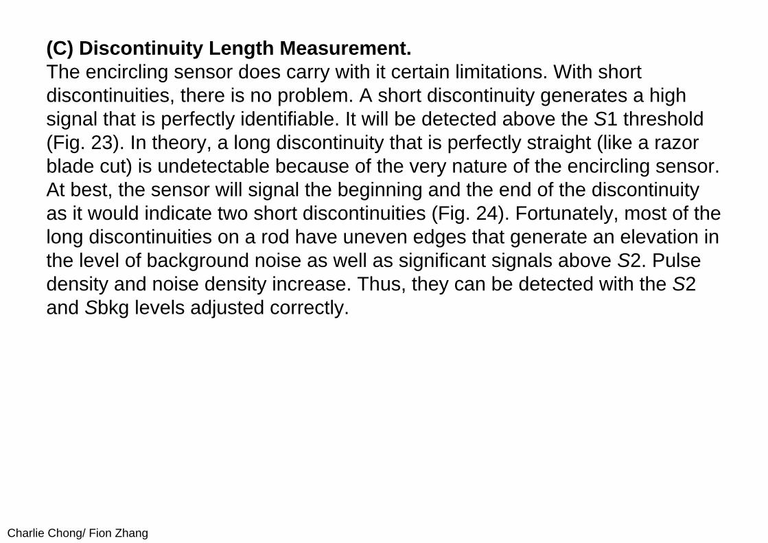
(C) Discontinuity Length Measurement. The encircling sensor does carry with it certain limitations. With short discontinuities, there is no problem. A short discontinuity generates a high signal that is perfectly identifiable. It will be detected above the S1 threshold (Fig. 23). In theory, a long discontinuity that is perfectly straight (like a razor blade cut) is undetectable because of the very nature of the encircling sensor. At best, the sensor will signal the beginning and the end of the discontinuity as it would indicate two short discontinuities (Fig. 24). Fortunately, most of the long discontinuities on a rod have uneven edges that generate an elevation in the level of background noise as well as significant signals above S2. Pulse density and noise density increase. Thus, they can be detected with the S2 and Sbkg levels adjusted correctly.
Charlie Chong/ Fion Zhang
14.6.2 High Speed Testing of Hot Wire and Hot TubesNondestructive testing of hot wire differs from other test processes in one essential aspect: production speed. Speeds up to 50 m·s–1 (112 mi·h–1) are routine and speeds up to 100 m·s–1 (224 mi·h–1) are not unusual. Material flow and test data flow from 100 percent surface testing are extremely high. Online nondestructive testing in the production line is a cybernetic process. Different feedback mechanisms with different time responses occur in such a process, depending on the type of discontinuities and the information about detected discontinuities.
Charlie Chong/ Fion Zhang
(I) Hot Aluminum Products
(A) Hot Rolled Aluminum Wire. Aluminum wire having a temperature of about 300 °C (570 °F) and a diameter of about 15 mm (0.6 in.) is continuously tested with the eddy current unit at 10 m·s–1 (22 mi·h–1). The discontinuities are marked immediately with a paint that resists heat up to 500 °C (930 °F). The marked discontinuities are controlled visually and cut out before cold drawing. The eddy current test record and the micrographs of some typical discontinuities are shown in Fig. 25. Extremely small discontinuities are of less interest because they are removed by the cold drawing process. The representation of dangerous, hard ferrous inclusions is out of proportion to their occurrence. Because of the high magnetic permeability of iron, even small iron inclusions are detected.
Charlie Chong/ Fion Zhang
(B) Hot Formed Aluminum Tubes. Another successful application of eddy current testing is in aluminum alloy tube production. Aluminum alloy tubes are produced at about 1 m·s–1 (2.2 mi·h–1) at about 450 °C (840 °F) with an extrusion press. Directly after the press, the material flow through the eddy current test is nearly continuous. Figure 26 shows eddy current indications of an extruded tube of 16 mm (0.63 in.) diameter with drilled holes according to the specification and indicated with a good ratio of signal to noise. Because only small differences exist between hot and cold aluminum, these typical test results, which have beenattained by a test of a cold tube, are also valuable for hot material.
Charlie Chong/ Fion Zhang
(II) Welded Steel TubesIn one installation, welded steel tubes are tested by an eddy current system just behind the calibration mill in a welded steel tubing line. Transverse welds and typical discontinuities are indicated with a high ratio of signal to noise by the test instruments and an automatic saw is activated by the output signals. This eddy current test obviates hydrostatic testing for this product.
Charlie Chong/ Fion Zhang
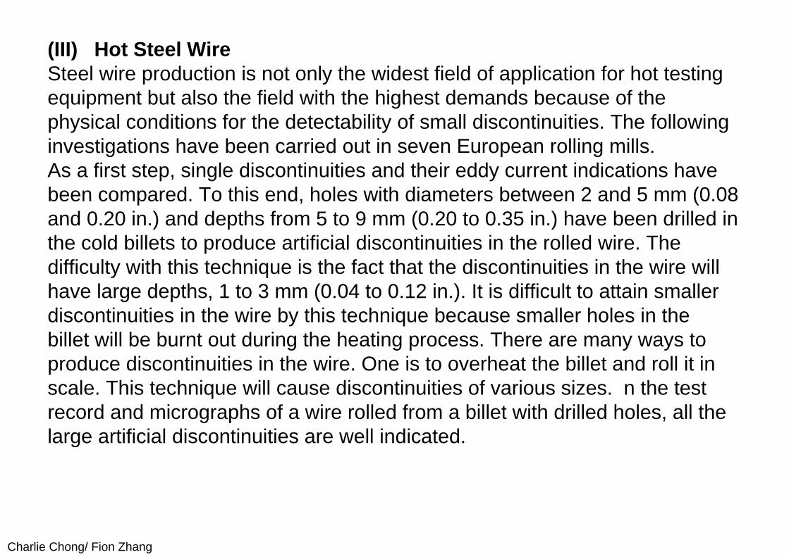
(III) Hot Steel WireSteel wire production is not only the widest field of application for hot testing equipment but also the field with the highest demands because of the physical conditions for the detectability of small discontinuities. The following investigations have been carried out in seven European rolling mills.As a first step, single discontinuities and their eddy current indications have been compared. To this end, holes with diameters between 2 and 5 mm (0.08 and 0.20 in.) and depths from 5 to 9 mm (0.20 to 0.35 in.) have been drilled in the cold billets to produce artificial discontinuities in the rolled wire. The difficulty with this technique is the fact that the discontinuities in the wire will have large depths, 1 to 3 mm (0.04 to 0.12 in.). It is difficult to attain smaller discontinuities in the wire by this technique because smaller holes in the billet will be burnt out during the heating process. There are many ways to produce discontinuities in the wire. One is to overheat the billet and roll it in scale. This technique will cause discontinuities of various sizes. n the test record and micrographs of a wire rolled from a billet with drilled holes, all the large artificial discontinuities are well indicated.
Charlie Chong/ Fion Zhang
14.6.3 ConclusionOnline applications to metals demonstrate the speed and effectiveness of electromagnetic testing for the control of process and product quality. The method’s widespread use in primary metals production saves that industry many millions of dollars annually and provides the world with stronger and safer products. In addition to the detection of cracks, seams, inclusions and other discontinuities that occur randomly, it is possible to detect repetitive discontinuities caused by broken or cracked rollers. Overheated billets and other problems that occur as a function of time are also detectable.

Charlie Chong/ Fion Zhang
14.7 Nondestructive testing of nonferrous tubes, in particular copper tubes
14.7.1 Introduction Tubes made of nonferrous metals are manufactured for an extremely wide variety of applications and must consequently meet the applicable requirements. Proof must be furnished that the requirements are met. Some of these requirements relate to testing for leaks and freedom from surface damage on the products. These requirements can be met using nondestructive testing methods. Nondestructive testing, in particular eddy-current testing as one of these methods, has long proven its worth for in-process testing of these products.
http://www.tubenet.org.uk/technical/foerster.html
Charlie Chong/ Fion Zhang
ABOUT THE AUTHOR: Hartmunt Kümmel, Export General Sales Manager, has been with Institut Dr. Förster for over 30 years, having begun in the development and service department. He has specialized throughout his Förster career in the field of Eddy Current and Magnetic flux leakage technology.
Hartmut Kümmel, INSTITUT DR. FÖRSTER, Germany
http://www.tubenet.org.uk/technical/foerster.html
Charlie Chong/ Fion Zhang
Tubes made of copper are particularly important in this respect, both as regards quantity and as regards the test requirements. Most of these products are used for piping, heat exchangers, air-conditioning and cooling. The need for testing, both as regards quantity and as regards requirements, increases as tube dimensions decrease. There are a number of standards covering nondestructive testing stipulating minimum requirements applicable to quality. These requirements can be met using the eddy-current through-type coil method. However, many users and manufacturers are now applying far more stringent test requirements. This is related to the fact that tubes with thinner and thinner walls are being used in order to reduce the quantity of material used and in order to cut costs. These more stringent requirements can be met only with eddy-current testers with rotating scanning probes.
The punctiform点状 probes of these testers provide a far higher flaw resolution, thus allowing detection of even small linear flaws of shallow depth. This application is always implemented together with through-type coils in order to detect all flaws over the entire surface reliably even at high throughput speeds.

Charlie Chong/ Fion Zhang
Extensive experience is available in relation to integration of the testers at a suitable point on the production lines - frequently directly in the drawing units or rewinding units. Particular attention must be paid, above all, to guidance of the material in order to achieve optimum test results and allow problem-free use.
Moreover, nondestructive testing can now perform far more extensive tasks than simply checking that the end product if free of flaws. The test represents an important measure, the results of which allow statements to be made on the condition of the production lines. Consistent use allows process deficiencies to be detected at an early point, allows condition-dependent maintenance and servicing of the production facilities and thus helps both to enhance the quality of production and to cut production costs.
Charlie Chong/ Fion Zhang
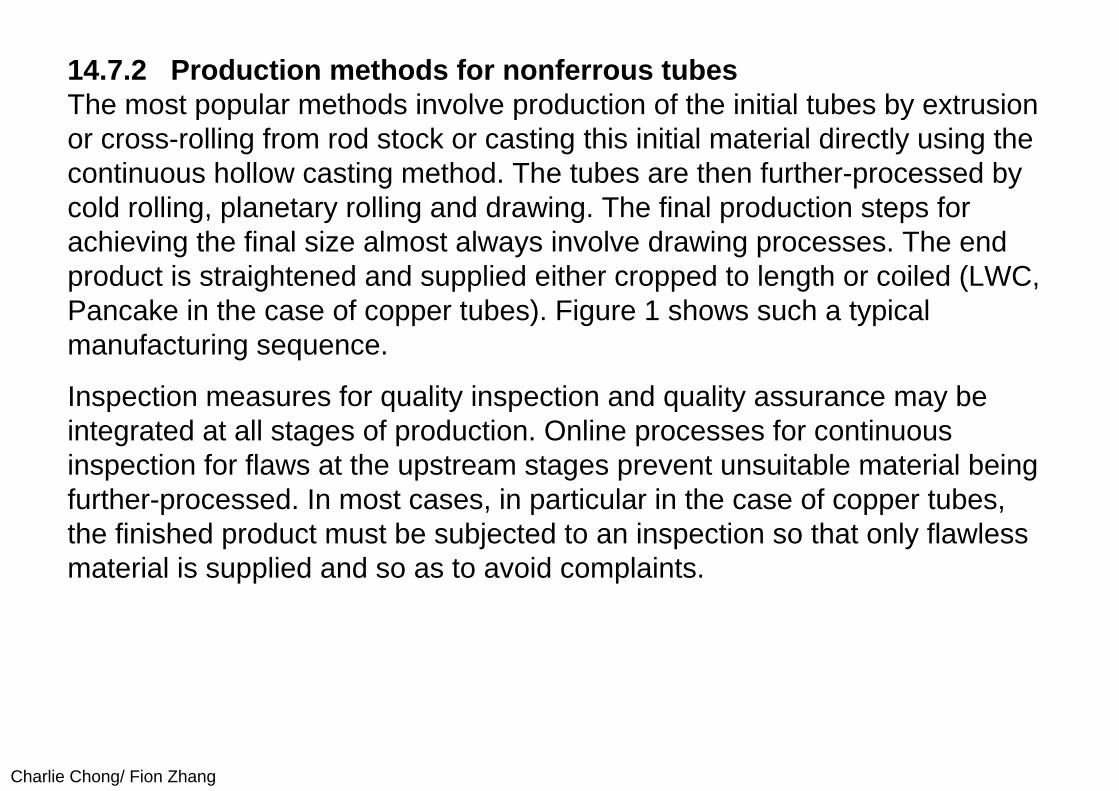
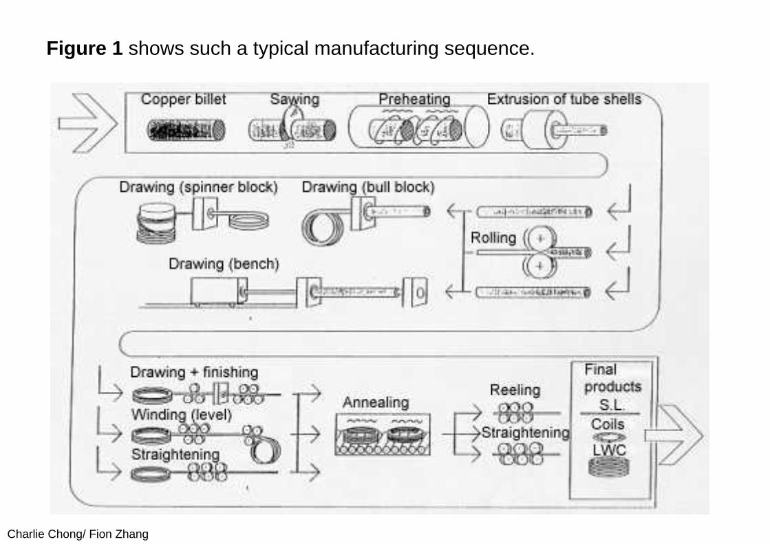
14.7.2 Production methods for nonferrous tubesThe most popular methods involve production of the initial tubes by extrusion or cross-rolling from rod stock or casting this initial material directly using the continuous hollow casting method. The tubes are then further-processed by cold rolling, planetary rolling and drawing. The final production steps for achieving the final size almost always involve drawing processes. The end product is straightened and supplied either cropped to length or coiled (LWC, Pancake in the case of copper tubes). Figure 1 shows such a typical manufacturing sequence.
Inspection measures for quality inspection and quality assurance may be integrated at all stages of production. Online processes for continuous inspection for flaws at the upstream stages prevent unsuitable material being further-processed. In most cases, in particular in the case of copper tubes, the finished product must be subjected to an inspection so that only flawless material is supplied and so as to avoid complaints.
Charlie Chong/ Fion Zhang
Figure 1 shows such a typical manufacturing sequence.
Charlie Chong/ Fion Zhang
14.7.3 Nondestructive testing14.7.3.1 Test methodsIt is largely eddy-current methods that are used for nondestructive testing for leaks and surface flaws. Basically, two methods are available:
■ Through-coil method: The material is transported axially through an enclosing eddy-current coil. To date, this is the most frequently used method which can meet therequirements of the standards applicable to copper tubes for instance.
■ Rotating scanning probe method:The material is transported axially through the hollow shaft of a rotating tester. During this process, the surface is scanned on helical tracks by eddy-current scanning probes. These units achieve exceedingly high test sensitivities for long-drawn-out, natural production flaws of low depth, detection of which is becoming more and more important today.
Figure 2 shows the principles of the methods described above. The physical properties and the specific details of the units based on these methods are described in greater detail in the Section entitled Testers.

Charlie Chong/ Fion Zhang
Figure 2. Rotating Scanning- and Through Coil methods
Charlie Chong/ Fion Zhang
14.7.3.2 Test requirementsGenerally conventional requirements applicable to nondestructive testing are as follows:
Leakage testing Compliance with national or international standards ISO 9000 requirements Monitoring and enhancement of the manufacturing process
Eddy-current testing is able to meet all the above requirements.
Charlie Chong/ Fion Zhang
Testing of initial (parent) material in the manufacturing process
Initial material (parent material) is tested in cases in which information on the quality of the product prior to further processing steps is to be obtained as early as the preceding steps of the production process. This avoids unnecessary costs as the result of further-processing unsuitable material. However, this also allows the manufacturing process itself to be monitored and controlled. Tests during this phase may be necessary in order to meet the requirements of controlled production in accordance with ISO 9000. Evaluation of the test results and analysis of the causes, as methods for enhancing the process, may contribute substantially to cutting costs. Many manufacturers have already installed initial (parent) material tests. Testing is conducted in this case on the basis of internal targets.
Charlie Chong/ Fion Zhang
Testing the finished product
Testing of the finished product is generally conventional but is mandatory in the case of tubes made of copper and copper alloys. A series of Standards relating to testing of the finished product (Figure 3), exists for such tubes in particular.

Charlie Chong/ Fion Zhang
Figure 3. Test standards
Charlie Chong/ Fion Zhang
Standards
The Standards listed below and published by various institutions in the individual countries are the most important Standards for tubes made of copper and copper alloy for general applications and for heat exchangers, air-conditioning equipment and pipes for sanitary applications (water and gas):
ASTM E 243 JIS H 0502 prEN 1971 DKI 781 ISO 1635
The Standards prescribe the test flaws to be used, the methods for instrument setting and, in some cases, the procedures for flaw evaluation. In general, bores through the wall are defined as reference flaws. ASTM 243-90 also foresees filed notches of defined depth. The table in Figure 4 provides an overview.
Charlie Chong/ Fion Zhang
The prEN 1971 Standard is the most comprehensive Standards for tubes made of "copper and copper wrought alloys”. They define "local discontinuities” and "non-local discontinuities”. Bores are used for setting the sorting limits.
Application of the Standards on units with through-type coils or rotary scanning
The above-specified Standards for copper tube testing are tailored to the use of through-type coils and are complied with by these instruments. The Standards currently make no distinctions between testers with through-type coils and testers with rotary scanning, apart from the fact that, in some cases, different threshold settings are permitted. To date, there are no Standards specific to rotating instruments.
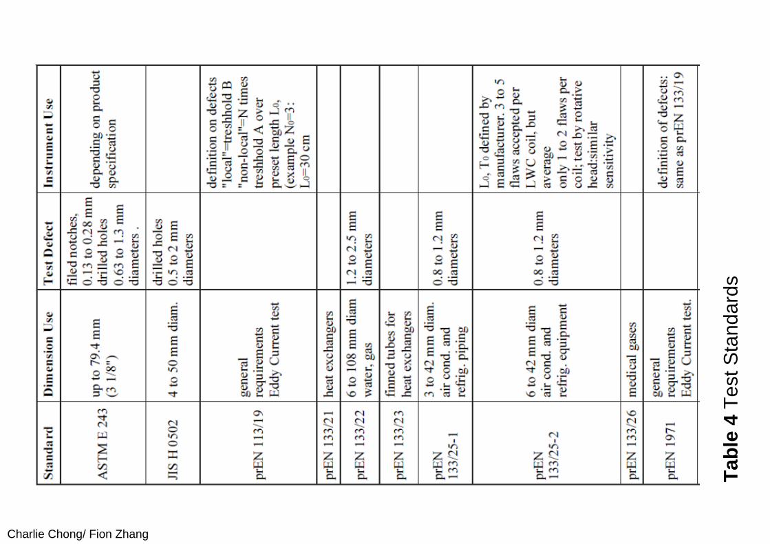
Charlie Chong/ Fion Zhang
Tabl
e 4
Test
Sta
ndar
ds
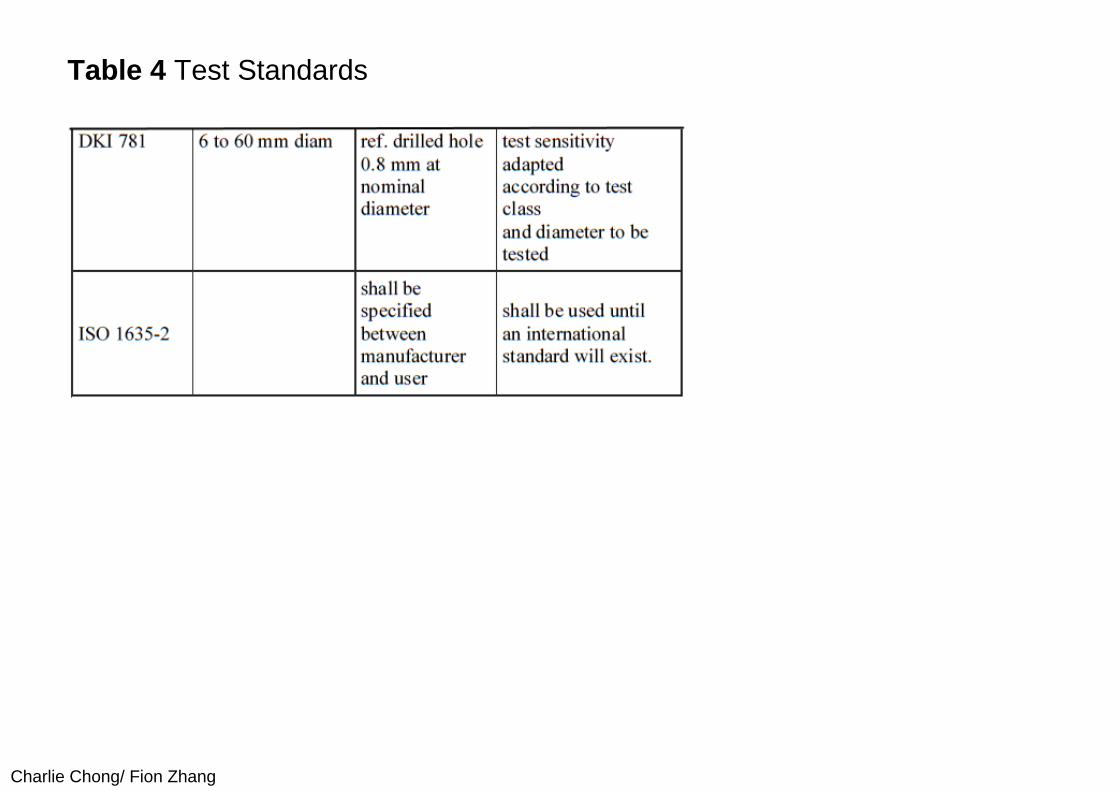
Charlie Chong/ Fion Zhang
Table 4 Test Standards
Charlie Chong/ Fion Zhang
14.7.3.3 Special test requirements exceeding the requirements of the Standards
Since many of the heat exchanger tubes now feature extremely thin walls (down to 0.3 mm) and since use of internally finned tubes is now also more popular, the flaw sensitivity achievable with the through-type coils is now no longer sufficient for quality-conscious manufacturers and users. Very frequently, Japanese manufacturers or those manufacturing for the Japanese market, but also European manufacturers, impose test requirements extending well beyond the requirements of the Standards and the industrial standard conventional to date. This involves detecting other types of manufacturing flaws with a very shallow depth.
Charlie Chong/ Fion Zhang
For example, this includes "line flaws” or "zipper defects” which are not detected with the through-type coil method. Roating instruments can perform this task adequately only because they allow a correspondingly higher sensitivity to be achieved.
However, using only rotating instruments is inadequate at the throughput speeds which are very frequently high since the scanning track coverage of the surface is incomplete, thus not allowing the bores prescribed by the Standards to be reliably detected. In such cases, it is advisable to use a combination of through-type coils and rotating instruments. This combination of test methods meets the stringent requirements as imposed today by demanding manufacturers and users.
Charlie Chong/ Fion Zhang
14.7.4 Test instruments14.7.4.1. Mode of operation of the Eddy Current test methodThe test method is in accordance to DIN 54140 detailed described. The encircling test coil´s primary (field) winding is supplied with a alternating current and induces „Eddy Currents" in circumferential direction of the test piece. Defects displace locally the path of the Eddy Currents. Those changes of the Eddy Current cause variations of the voltage in the secondary windings of the coil when the test piece passes the coil system. Phase and amplitude of these voltage variations are evaluated and provide an indication of the size and type of defect. The complete transmitter system of this unit consists of a D. C. magnetization yoke into which the test coils matching the diameter of the test piece are inserted.
Charlie Chong/ Fion Zhang
14.7.4.2 DEFECTOMAT through-type coil instrumentsThis method is the simplest test method which, as already mentioned, involves the material moving axially through a coil surrounding the material. The diameters of the coils are matched to the material under test. The diameters available range between 0.3 and 180 mm. The instruments can be used, in principle, at very high throughput speeds ranging up to 120 m/second. Ultra-modern computer systems are used to process the signals of the test system generated by the eddy-current effects. These systems feature menu-prompted operation with softkeys on the controller as the central operator-control, display and control unit. Extensive documentation of all instrument parameters and results is possible thanks to extensive storage and output facilities. All important instruments functions are monitored. The test frequencies can be selected in a broad range. Figure 5 shows instrument electronics of this type.

Charlie Chong/ Fion Zhang
Figure 5. Testing instrument
Charlie Chong/ Fion Zhang
The newly developed software for copper testing allows for the special requirements of the test specifications to be applied when further-processing the signals, such as the test specifications of European Standards prEN 1971 for tubes made of "copper and copper wrought alloys”: These standards define "local discontinuities” (local defects) and "non-local discontinuities” (non-local defects). Prescribed bores are used to set the first sorting limit (threshold) for local defects. A second sorting limit (threshold) set to a far low flaw signal magnitude is used to detect non-local defects, whereby a flaw is "detected” only if an adjustable number of threshold transgressions occurs within an adjustable length section (flaw density). The flaws determined in this way are considered as a local defect. The Standard does not prescribe the setting of the second threshold or the number of threshold transgressions which must then be rated as a flaw. These parameters are defined by the user or his customer. Figure 6 recapitulates the evaluation requirements.
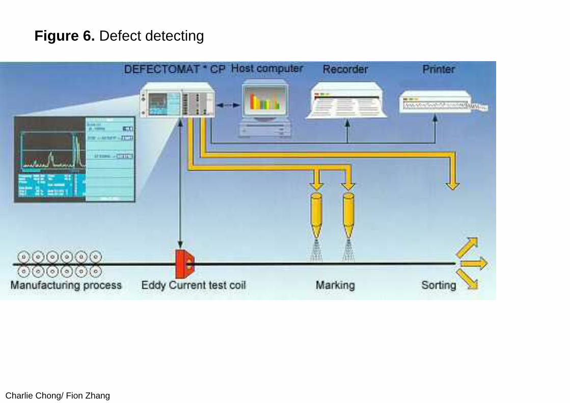
Charlie Chong/ Fion Zhang
Figure 6. Defect detecting
Charlie Chong/ Fion Zhang
Screen display / loggingThe test instruments must comply with the prescribed test requirements with absolute certainty. Moreover, the test must be documented. Nowadays, these are the determining factors in the sector of quality inspection and quality assurance since producer liability for products is increasing continually in importance. For this reason, the electronic systems of the testers incorporate extensive documentation options. Certain forms of evaluation and representation have been introduced for applications in the field of copper tube testing. Such screen displays of the results are continuous display of the analogue amplitudes over the workpiece length and result listings for coils or workpieces. Figure 8 shows an evaluation report. To date, the Standards do not prescribe any aspects of logging but prEN 1971 implies that inspection documents will be stipulated in future by the Standards Commission.

Charlie Chong/ Fion Zhang
14.7.4.3 Rotary scanning instruments, CIRCOGRAPHThe scanning principle with rotating eddy-current scanning probes is suitable for detection of flaws with a depth of approx. 30 µm and deeper, regardless of how these flaws are distributed over the length. The probes rotate at high speed about the material under test which is moved longitudinally and scan its surface helically. Each of the punctiform-action scanning probes scans only a small area of the material's surface at any one moment. This concentration on a very small part of the overall circumferential area means that even a minute material flaw represents a major disturbance. The rotating probes thus reliably indicate ultra-small material flaws with maximum resolution.
Charlie Chong/ Fion Zhang
One crucial advantage of the rotary scanning method over the through-type coil relates to flaw detection of long-drawn-out flaws. Whilst the through-type coil generates a signal only at the leading and trailing edges owing to its differential action in test direction, the rotating probe passes over the flaw with each revolution and emits a signal each time. Long-drawn-out flaws are thus indicated over their entire length and at the correct depth. For physical reasons, a high flaw sensitivity can be achieved better the smaller the rotating probe used is and the smaller the air gap between probe and material surface. Influences of the air gap which cannot be maintained precisely constant can be compensated for within certain limits electronically with an automatic compensation circuit in order to maintain a constant test sensitivity.
Charlie Chong/ Fion Zhang
Owing to the requirements and the technically sophisticated demands, rotating test systems are the most highly developed eddy-current test instruments available. For technical reasons relating to the process, the test heads with the rotating probes incorporated in these testers have a very small clearance of only a few tenths of a millimeter to approx. 2 mm from the test piece surface with differently set material diameters and, at the same time, central location of the test piece. This requires very precise preconditions for diameter setting in order to achieve reproducible test settings.Arrays with axially moveable test heads (quiver system) or rotary-mounted test head levers have proven successful in practice. On the version with axially moveable test heads, the diameter presettings are generally made by turning a spiral or cam disc. One disadvantage of this system is the fact that it is absolutely essential to protect the test head against damage. A pivoted lever represents a relatively low-cost test head array which can deflect when it contacts the test head in order to avoid such damage.
Charlie Chong/ Fion Zhang
High-performance rotating instruments in four diameter ranges (Ro 14, Ro 30, Ro 65, Ro 130) with testable diameters ranging from 2 to 130 mm are available as tried-and-tested units. Two to eight channels and rotating probes with 1.5 mm, 2.5 mm or 5 mm track width are used, depending on the required flaw specifications and testing performance. The rotating heads are selected on the basis of the diameter range.
Depending on probe design, the rotating heads Ro 14 and Ro 30 to be used for the sector of small copper tubes to which this article is chiefly devoted permit testing without omission at speeds of 3 m/second. Since speeds of up to 8 m/second or more are used in the rewinding systems, this results in gaps between the test tracks (diagram Figure 11). Consequently, the rotating instrument is generally used together with a through-type coil instrument.
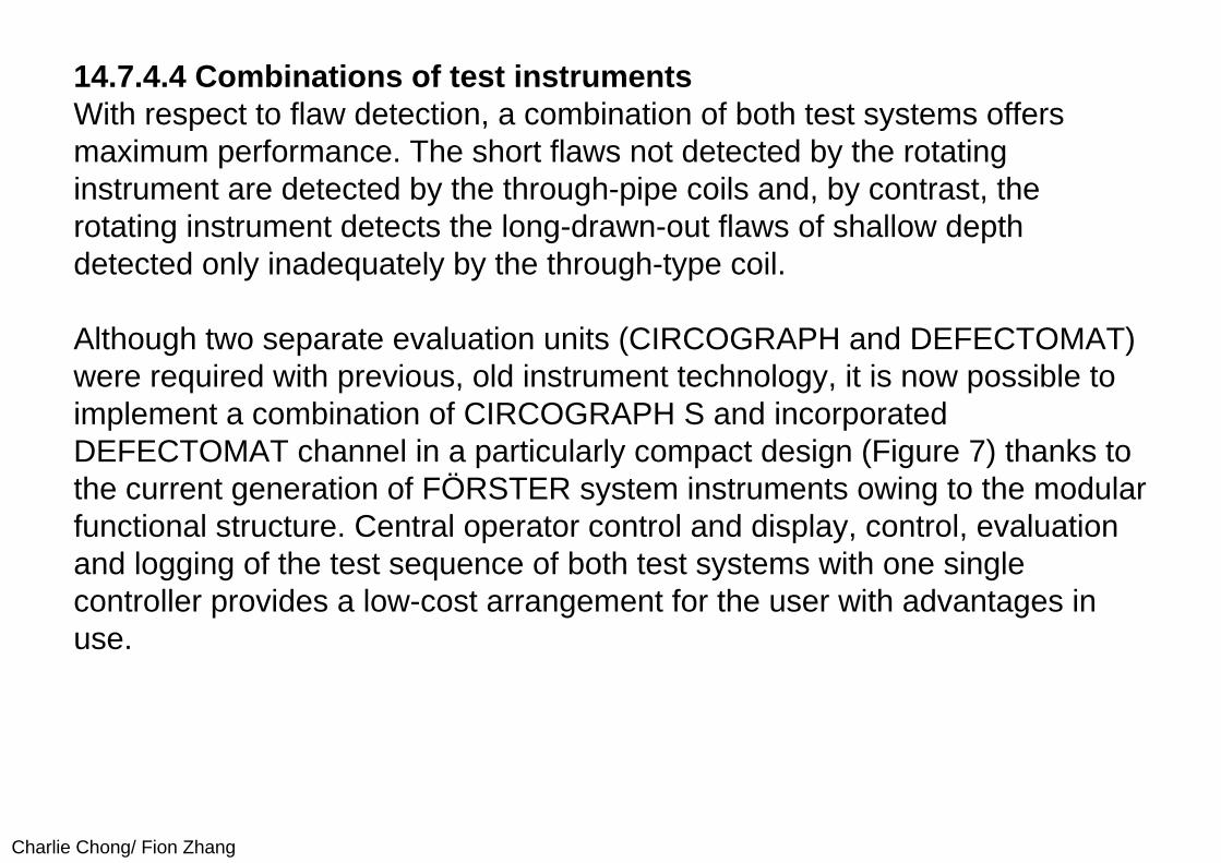
Charlie Chong/ Fion Zhang
14.7.4.4 Combinations of test instrumentsWith respect to flaw detection, a combination of both test systems offers maximum performance. The short flaws not detected by the rotating instrument are detected by the through-pipe coils and, by contrast, the rotating instrument detects the long-drawn-out flaws of shallow depth detected only inadequately by the through-type coil.
Although two separate evaluation units (CIRCOGRAPH and DEFECTOMAT) were required with previous, old instrument technology, it is now possible to implement a combination of CIRCOGRAPH S and incorporated DEFECTOMAT channel in a particularly compact design (Figure 7) thanks to the current generation of FÖRSTER system instruments owing to the modular functional structure. Central operator control and display, control, evaluation and logging of the test sequence of both test systems with one single controller provides a low-cost arrangement for the user with advantages in use.
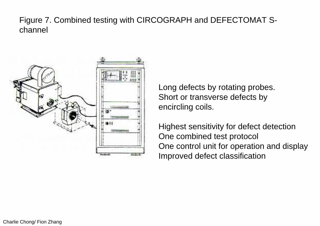
Charlie Chong/ Fion Zhang
Figure 7. Combined testing with CIRCOGRAPH and DEFECTOMAT S-channel
Long defects by rotating probes.Short or transverse defects byencircling coils.
Highest sensitivity for defect detection One combined test protocol One control unit for operation and display Improved defect classification
Charlie Chong/ Fion Zhang
14.7.5 Applications and integration in the production lines14.7.5.1 Integration of through-type coil instrumentsIn the majority of cases, testers with through-type coils are installed in rewinding systems. Figure 8 shows the basic arrangement. However, a whole number of instruments are also integrated in drawing systems. One of the leading manufacturers of tube drawing and rewinding systems is Messrs. Schumag whose lines are equipped with the DEFECTOMAT or CIRCOGRAPH testers within the framework of our more in-depth cooperation.
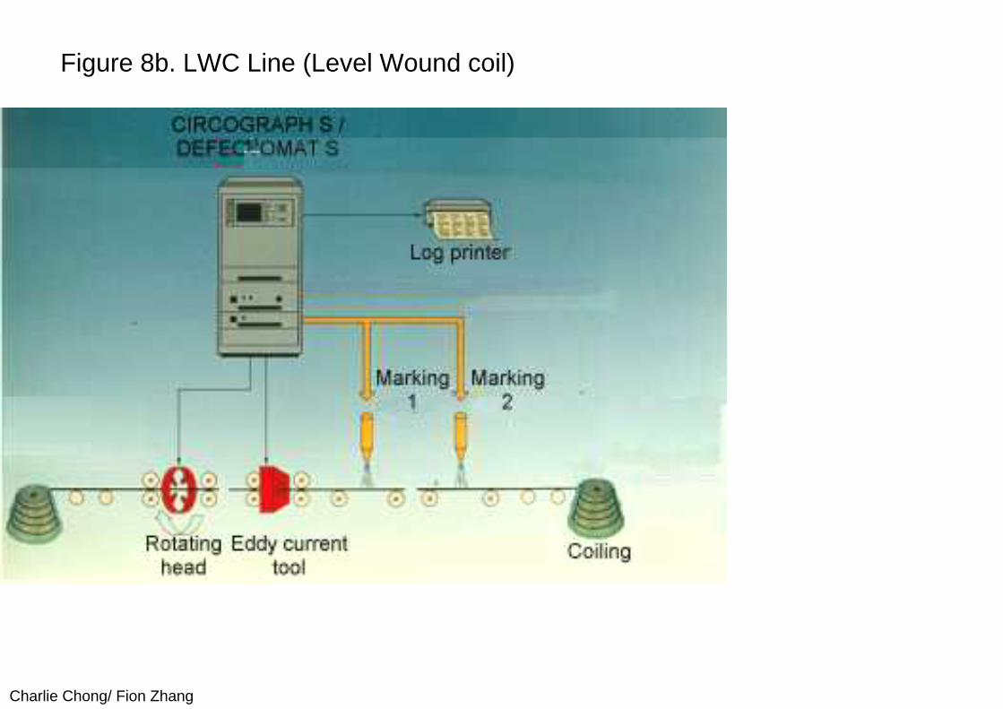
Charlie Chong/ Fion Zhang
Figure 8b. LWC Line (Level Wound coil)
Charlie Chong/ Fion Zhang
One of the important basic conditions for successful testing is precise material guidance. In both cases, the location between the straightening devices has proven to be the best when installing the transmitter system in the drawing machine or the rewinding systems (LWC or SCR). The material must be guided centrally, both horizontally and vertically, in the measurement coil area. In principle, this situation can be achieved if the transmitter system is installed between the horizontal and vertical straightening device provided the rolls are appropriately and correctly adjusted. In the simplest case, this measure suffices and it is also the cheapest method. Frequently however, adjustment of throughput centricity with these alignment rolls is either not desired for reasons relating to operation or is not easily possible owing to the differing diameters. A vertically adjustable fixture for the test coil holder can then be used. The coil holder may be pushed out or tilted out in order to take it offline. Very suitable guides have been designed using polished carbide-metal guide inserts, as also mentioned in conjunction with the test instruments with rotary scanning. Customers are also very satisfied with such guides since they reduce the incidence of abraded copper deposits on them as well.
Charlie Chong/ Fion Zhang
14.7.5.2 Integration of test instruments with rotary scanningThe characteristics and, in particular, the advantages of test instruments with rotary scanning have been explained in the preceding chapter. The clearances between probe and surface are only very small in order to achieve high test sensitivities. For this reason, guidance in this case must be particularly precise. A special guide device has been developed for testing the copper tubes, in particular the thin-walled copper tubes. This involves guides, each with two guide inserts with diameters which are slightly larger than those of the tubes under test on both sides of the instrument. This guides the material almost ideally centrally and free of vibration through the test instrument. In addition, the test heads are very well-protected against destruction as the result of deformed tube leading and trailing edges. Excellent experience has now been made with guides of this type in many applications, both with test head size Ro 14 and with test head size Ro 30.
Charlie Chong/ Fion Zhang
Figure 9 shows an example of an installation as is typical for a rewinding line. One through-type coil transmitter system and a rotating instrument Ro 30 areincluded. Since setting the correct height of the material with the straightening rolls is considered to be too difficult for the operating personnel, a lifting/sliding table has been included. This table is common to both instruments.
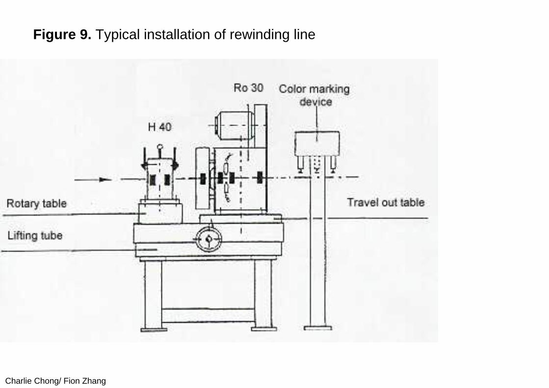
Charlie Chong/ Fion Zhang
Figure 9. Typical installation of rewinding line
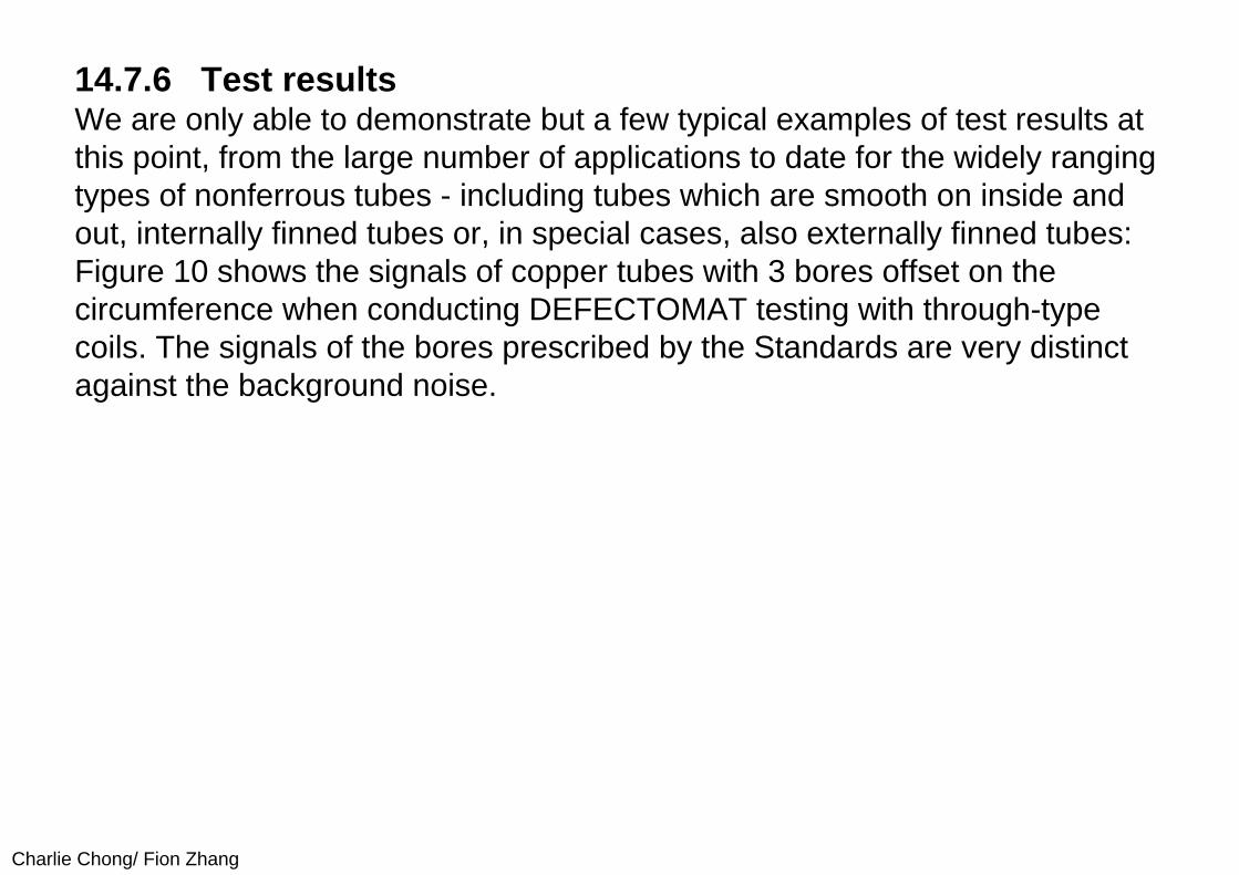
Charlie Chong/ Fion Zhang
14.7.6 Test resultsWe are only able to demonstrate but a few typical examples of test results at this point, from the large number of applications to date for the widely ranging types of nonferrous tubes - including tubes which are smooth on inside and out, internally finned tubes or, in special cases, also externally finned tubes: Figure 10 shows the signals of copper tubes with 3 bores offset on the circumference when conducting DEFECTOMAT testing with through-type coils. The signals of the bores prescribed by the Standards are very distinct against the background noise.
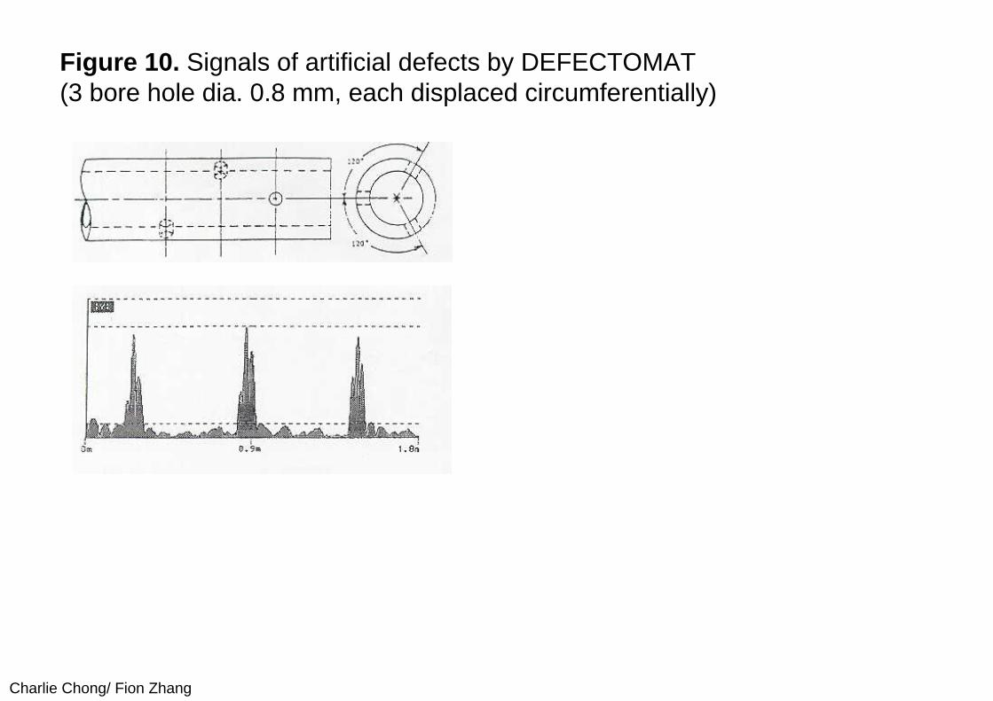
Charlie Chong/ Fion Zhang
Figure 10. Signals of artificial defects by DEFECTOMAT(3 bore hole dia. 0.8 mm, each displaced circumferentially)
Charlie Chong/ Fion Zhang
Figure 11 shows test results of copper tubes with 9.52 mm diameter and 0.4 mm wall thickness, as obtained from very small, long-drawn-out flaws when testing with the CIRCOGRAPH rotating tester (upper illustration). They indicate the excellent flaw sensitivity offered by this unit for this type of flaw. By contrast, the lower illustration shows the results of the DEFECTOMAT on which the signals of this type of flaw achieve only far lower amplitudes and would not yet exceed the threshold at the normal instrument setting which avoids pseudo shares.
Figure 11. EC-Test by CIRCOGRAPH S
Charlie Chong/ Fion Zhang
14.7.7 Benefits of testingObjective test results and corroborated documentation are determining factors in the sector of quality inspection and quality assurance owing to the liability of producers for their product. However, nondestructive eddy-current testing can do far more than simply sort the finished products into GO and NOGO parts. One important aspect nowadays is integration of testing in the manufacturing process. The resultant advantages are the capabilities of monitoring the process, avoiding downtimes and cutting maintenance and servicing costs. In conjunction with ISO 9000 or also independently of it, the test results can be used to draw conclusions as regards the quality of the process from flaw frequency trends. Manufacturing defects can be avoided by recognizing the problems in good time and taking appropriate measures. This method of drawing conclusions as regards the process and deriving measures to optimize the process from these conclusions is already being used successfully by certain customers (as they have confirmed to us, without, however, informing us of details of the action taken).
Charlie Chong/ Fion Zhang
The flaw frequency can also be used as an indicator for the need to carry out servicing and maintenance. It allows condition-related maintenance and servicing intervals to be introduced. This allows costs to be cut by comparison with fixed servicing and maintenance intervals. This is already being used successfully at another point - when drawing steel wire - in order to automatically detect wear on drawing dies from the change in noise level and, from this, to derive information on when maintenance and servicing need to be carried out, dependent on conditions. In future, multifunctional use of the testers for the above tasks will represent one of the most important tasks for nondestructive testing. On no account should the capabilities which it offers be ignored since they do, ultimately, allow production costs to be cut. Use of nondestructive testing pays off. It can save a great deal more than it costs.
Charlie Chong/ Fion Zhang
14.7.8 Nondestructive testing of other nonferrous products (rods, wire, section, strip and sheet) and applications for other materialsA detailed description of nondestructive testing of other products made of nonferrous materials at this point would go beyond the scope of this report. However, we shall briefly mention testing of copper rods and copper wire where testing with through-type coil instruments has been introduced to the greatest extent. Many testers are also used for sections, strips and sheets. The number of units used for steel tubes and steel wire - both through-type coil instruments and rotating instruments - runs into the thousands.
Charlie Chong/ Fion Zhang
14.7.9 Summary and conclusionFurther-processing plants virtually always produce complex, high-quality products and installations for chemical processes, supply, cooling and heating from nonferrous tubes. The material is highly deformed during processing. The requirements applicable to it are exceedingly high accordingly. Flaws and failures detected only in the end product mean high losses. Flaws which occur only during the application phase may lead to enormous claims for compensation in damages. No further-processing plant will thus use untested material. What is needed is flaw testing with a high detection sensitivity! The aim is:
■ Assured quality of the products by continuous testing, ■ Less complaints and lower costs and ■ Avoidance of problems resulting from product liability
Charlie Chong/ Fion Zhang
For testing of copper tubes considered in somewhat greater detail in this report, the Standards stipulated by various institutions represent only the minimum requirements. Nowadays, quality tubes must comply with far more stringent specifications. For instance, in order to improve heat transfer on heat exchangers, the wall thicknesses have been made thinner and thinner. Values of 0.3 mm are now already conventional. Test specifications of a Japanese manufacturer extending well beyond the Standards have been quoted as an example of requirements currently conventional. Such high test sensitivities for surface flaws now required by many users cannot be met with the conventional through-type coil method alone. The use of instruments with rotating scanning probes is essential for meeting these requirements.
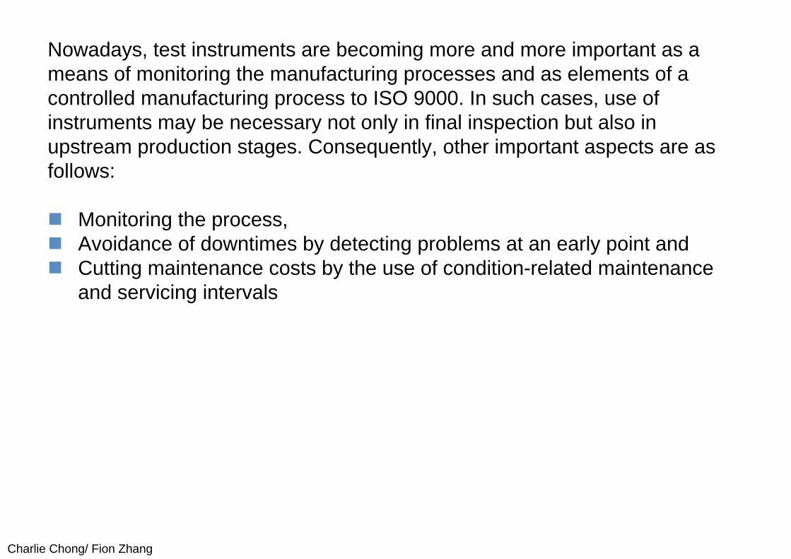
Charlie Chong/ Fion Zhang
Nowadays, test instruments are becoming more and more important as a means of monitoring the manufacturing processes and as elements of a controlled manufacturing process to ISO 9000. In such cases, use of instruments may be necessary not only in final inspection but also in upstream production stages. Consequently, other important aspects are as follows:
Monitoring the process, Avoidance of downtimes by detecting problems at an early point and Cutting maintenance costs by the use of condition-related maintenance
and servicing intervals
Charlie Chong/ Fion Zhang
Extended evaluation of the test results allows conclusions to be drawn as regards the process sequence or any necessary maintenance or servicing from trends in flaw frequency. This permits manufacturing flaws to be avoided by prompt maintenance and servicing resp. the introduction of condition-related maintenance and servicing intervals and resultant cost savings. The objectives specified above - quality assurance, reduction in complaints and rights of recourse owing to flaws and avoidance of unnecessary costs -are achieved by extensive use of nondestructive testing. Nowadays, using test instruments may no longer be considered as a cost factor. Rather, it can save far more than it costs!
The FÖRSTER company has been constructing rotating instruments for over 30 years now and test instruments with through-type coils for far longer. As a result, the experience which the company has acquired a wealth of experience in the use of test systems which meet today's requirements, i.e. cutting manufacturing costs and safeguarding competitiveness on the market.

Charlie Chong/ Fion Zhang
Casting
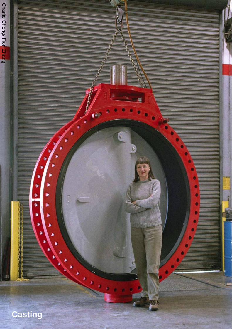
Charlie C
hong/ Fion Zhang
Casting

Charlie Chong/ Fion Zhang
Pipe Piercing - Wrought
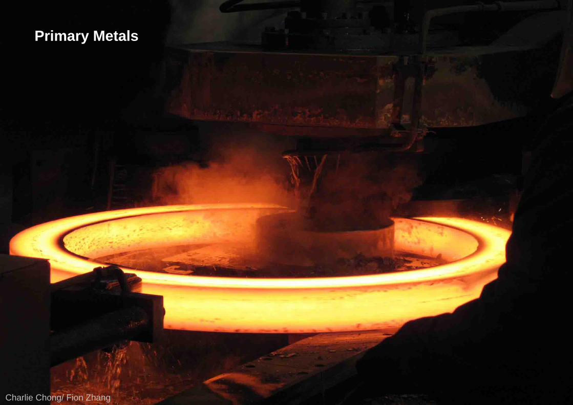
Charlie Chong/ Fion Zhang
Primary Metals

Charlie Chong/ Fion Zhang
Reading Joyshttp://www.filefactory.com/folder/75d751cbe768d192https://www.mediafire.com/folder/9elg8fo4zu28n/ET_Level_III
http://issuu.com/charlieccchonghttps://www.yumpu.com/user/charliechonghttp://www.slideshare.net/charliechong/presentationshttps://independent.academia.edu/CharlieChong1http://www.authorstream.com/charliechong/

Charlie Chong/ Fion Zhang
Good Luck!

Charlie Chong/ Fion Zhang