Embed Size (px)
Citation preview
Bifacial Si Cells for Space Applications
Fabricated Using Combined
Ion Implantation –Thermal Diffusion
Technology
Bifacial Si Cells for Space Applications
Fabricated Using Combined
Ion Implantation –Thermal Diffusion
Technology
G. Grigorieva, M. Kagan, K. Zviagina,
KVANT, Moscow , Russia,
L. Kreinin, N. Bordin, N. Eisenberg
Jerusalem College of Technology, Jerusalem, Israel
G. Grigorieva, M. Kagan, K. Zviagina,
KVANT, Moscow , Russia,
L. Kreinin, N. Bordin, N. Eisenberg
Jerusalem College of Technology, Jerusalem, Israel
OUTLINE
1. Space application of bifacial solar cells
2. n+-p-p+ bifacial cells produced by combined thermal
diffusion - ion implantation technology diffusion - ion implantation technology
3. Production and research achievements useful for
fabrication of terrestrial bifacial solar cell
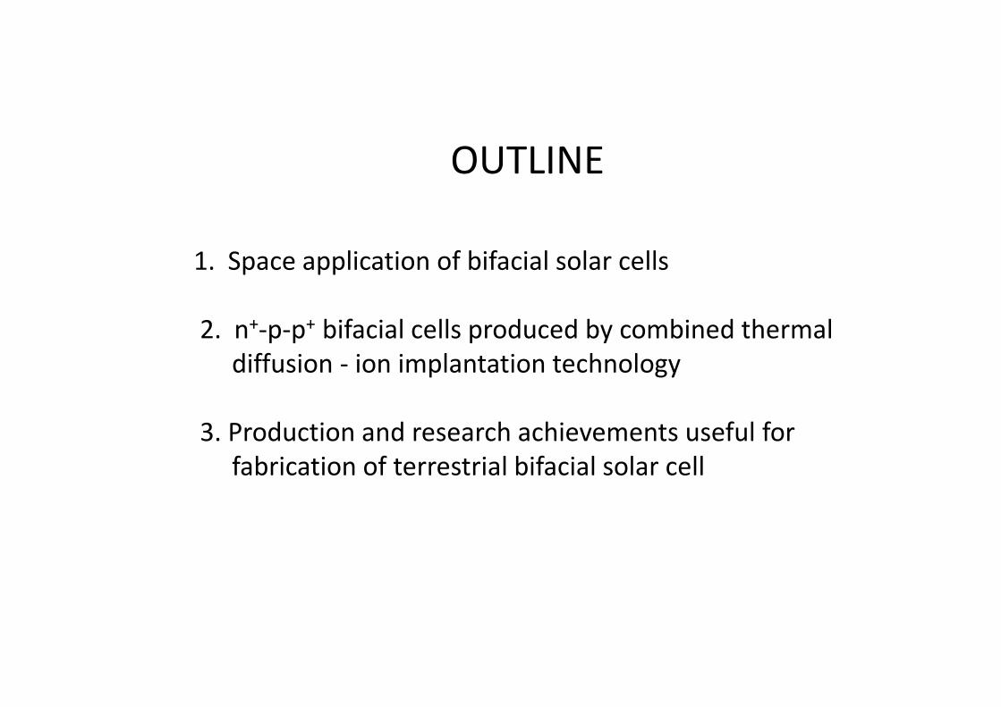
BIFACIAL SOLAR ARRAYS IN SPACE
Bifacial Si solar arrays were mounted on spacecrafts
"Zarya" and "Zvezda" of Russian segment of the ISS.
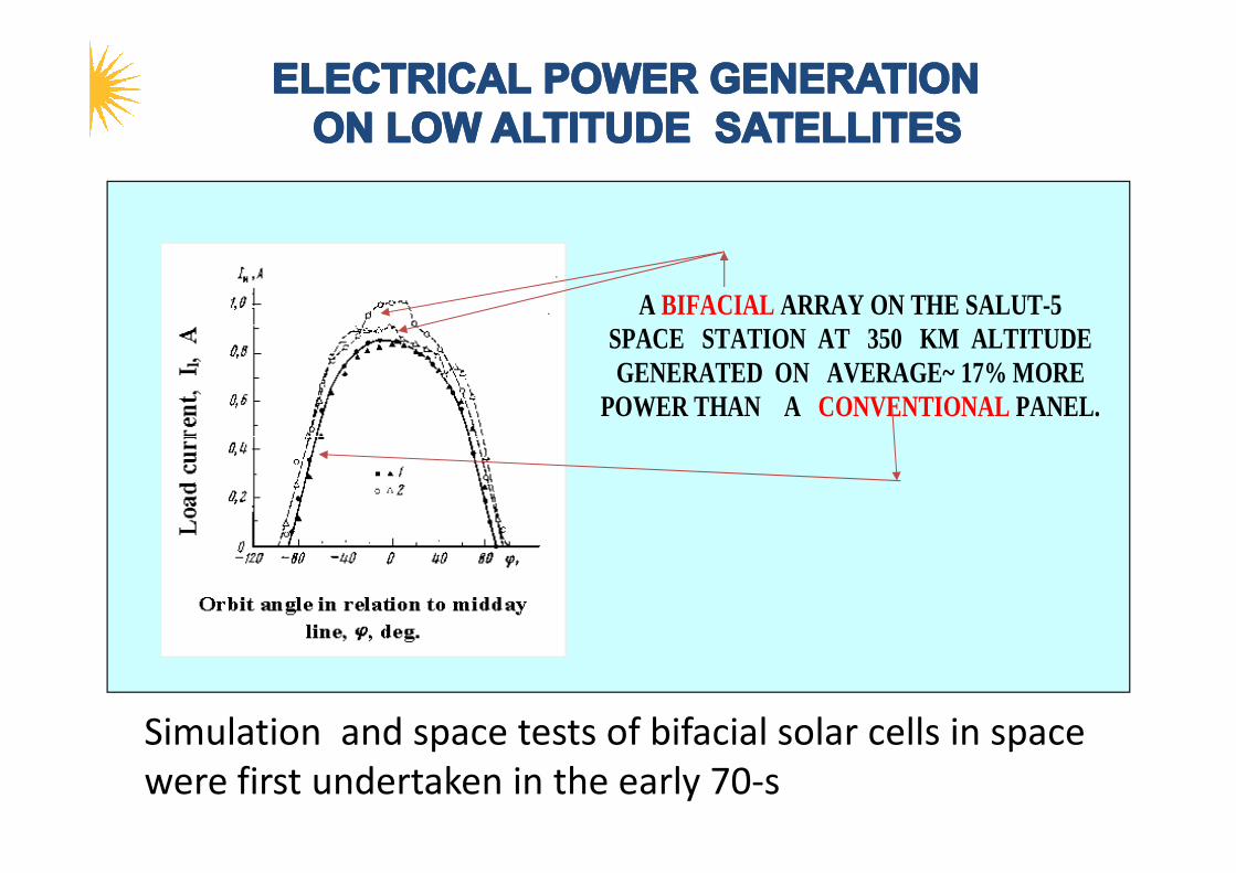
A BIFACIAL ARRAY ON THE SALUT-5 SPACE STATION AT 350 KM ALTITUDE GENERATED ON AVERAGE~ 17% MORE
POWER THAN A CONVENTIONAL PANEL.
Simulation and space tests of bifacial solar cells in space
were first undertaken in the early 70-s
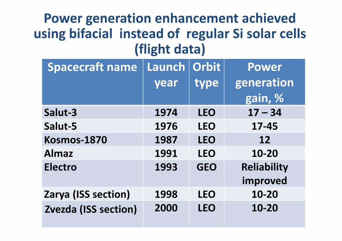
Power generation enhancement achieved using bifacial instead of regular Si solar cells
(flight data)
Power
generation
gain, %
Orbit
type
Launch
year
Spacecraft name
17 – 34LEO1974Salut-3
17-45LEO1976Salut-5 17-45LEO1976Salut-5
12LEO1987Kosmos-1870
10-20LEO1991Almaz
Reliability
improved
GEO1993Electro
10-20LEO1998Zarya (ISS section)
10-20LEO2000Zvezda (ISS section)
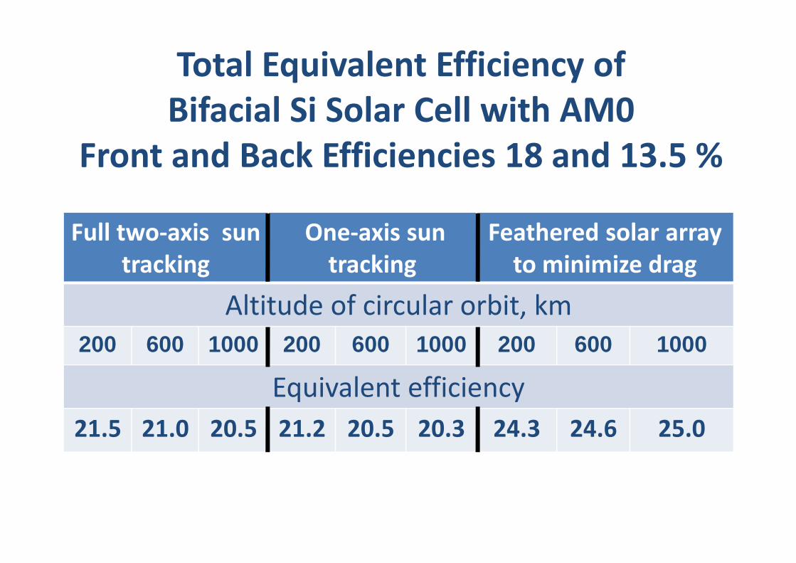
Total Equivalent Efficiency of
Bifacial Si Solar Cell with AM0
Front and Back Efficiencies 18 and 13.5 %
Feathered solar array
to minimize drag
One-axis sun
tracking
Full two-axis sun
tracking
Altitude of circular orbit, km
1000 6002001000 6002001000600200
Equivalent efficiency
25.024.624.320.320.521.220.521.021.5
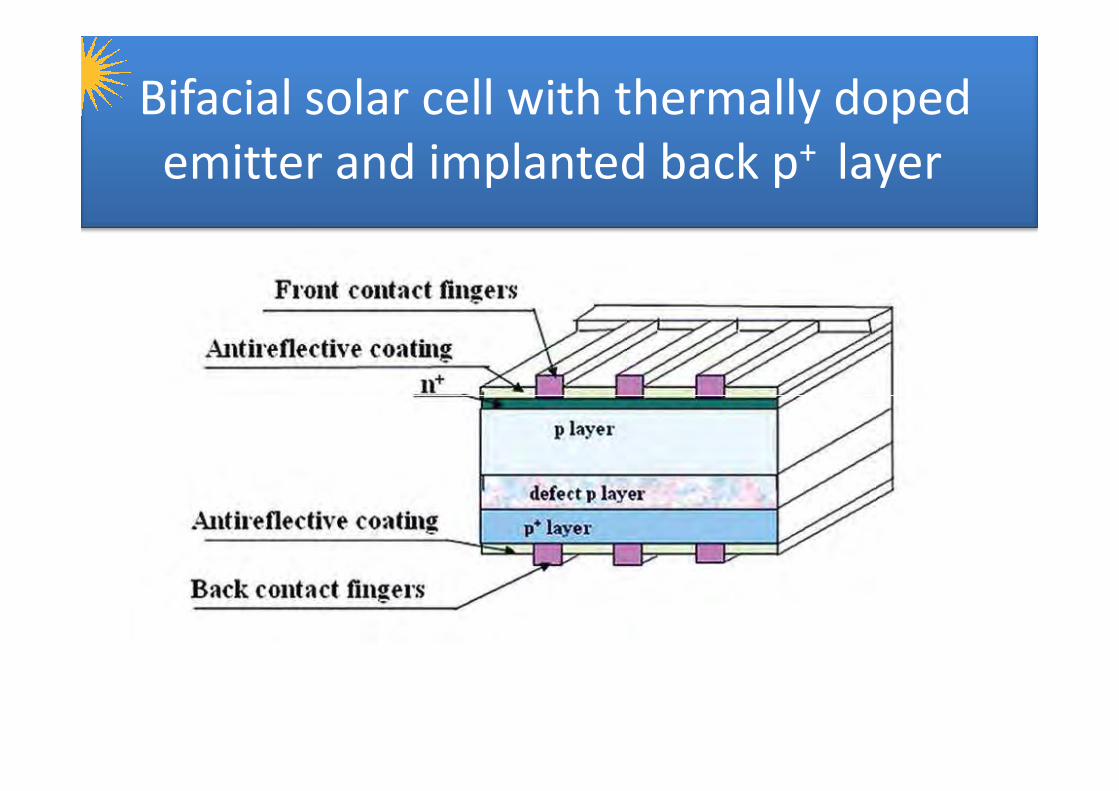
Bifacial solar cell with thermally doped
emitter and implanted back p+ layer
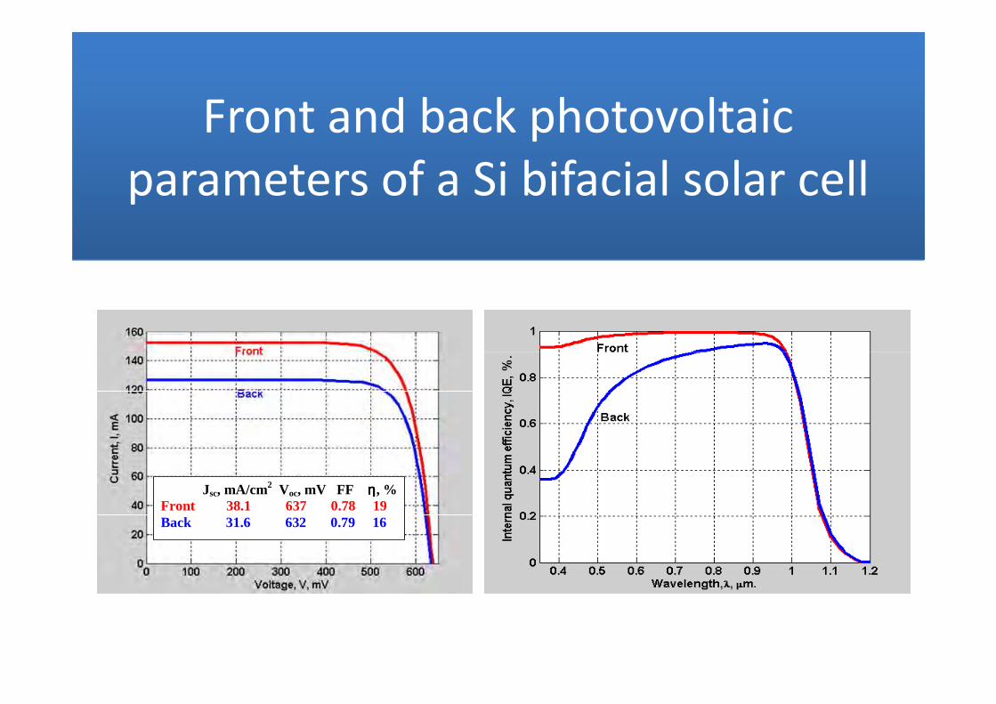
Front and back photovoltaic
parameters of a Si bifacial solar cell
Jsc, mA/cm2 Voc, mV FF ηηηη, % Front 38.1 637 0.78 19 Back 31.6 632 0.79 16
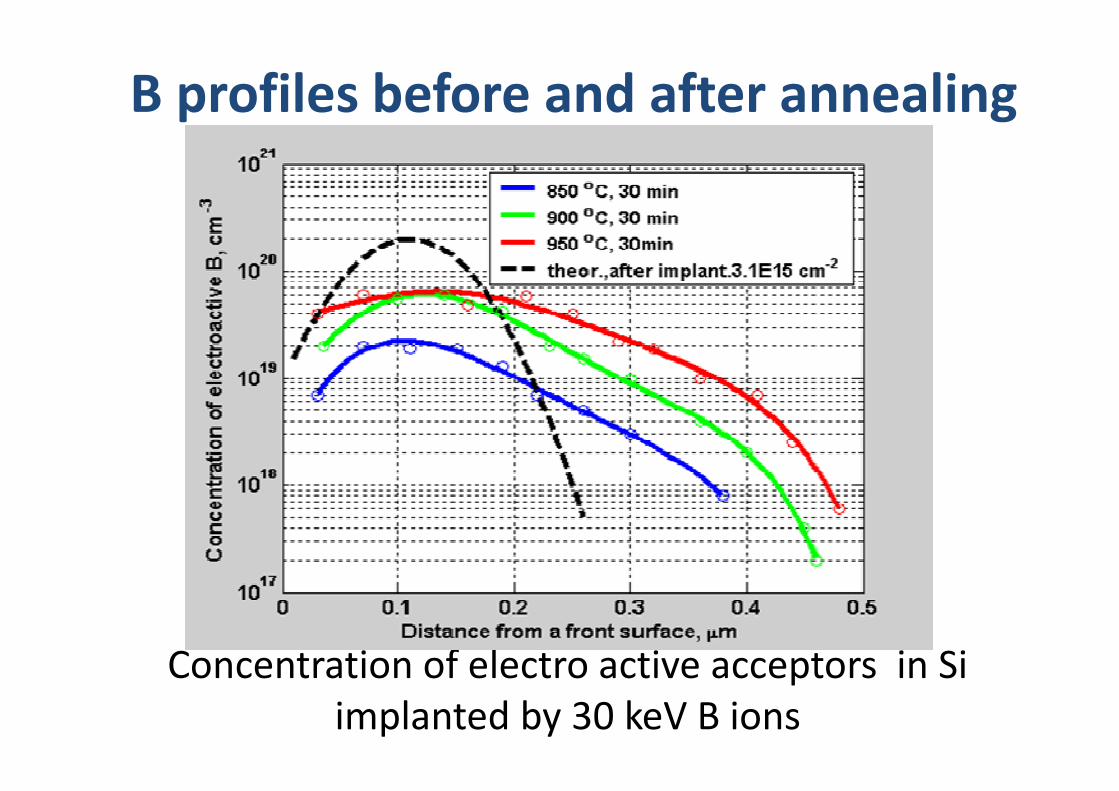
B profiles before and after annealing
Concentration of electro active acceptors in Si
implanted by 30 keV B ions
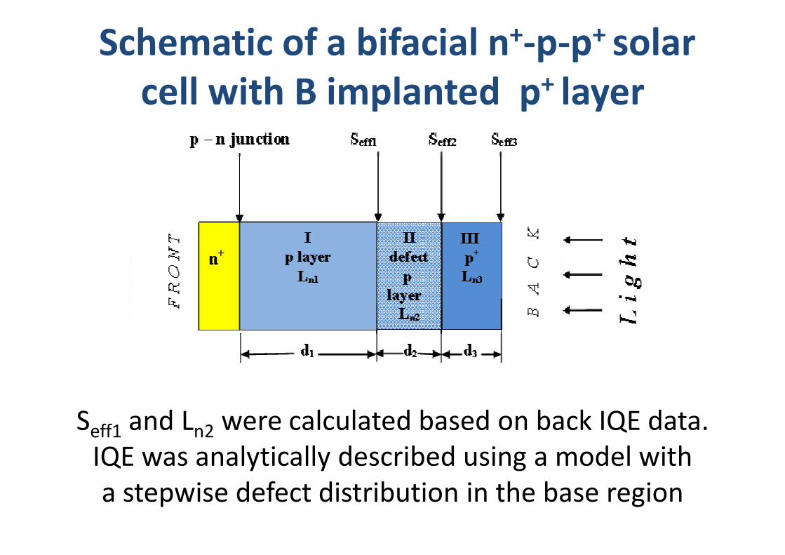
Schematic of a bifacial n+-p-p+ solar
cell with B implanted p+ layer
Seff1 and Ln2 were calculated based on back IQE data.
IQE was analytically described using a model with
a stepwise defect distribution in the base region
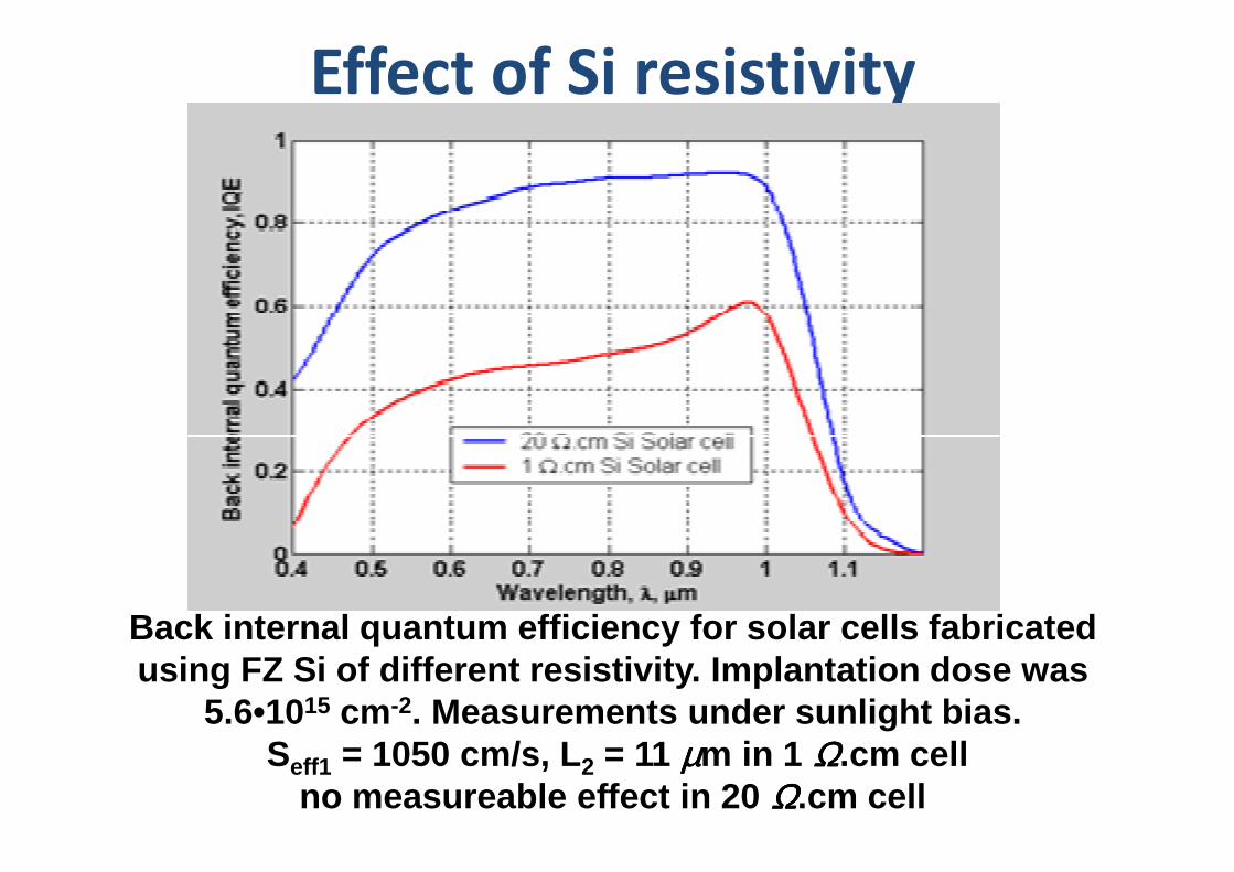
Effect of Si resistivity
Back internal quantum efficiency for solar cells fabricated using FZ Si of different resistivity. Implantation dose was
5.6•1015 cm -2. Measurements under sunlight bias.Seff1 = 1050 cm/s, L2 = 11 µµµµm in 1 ΩΩΩΩ.cm cell
no measureable effect in 20 ΩΩΩΩ.cm cell
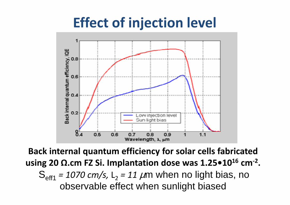
Effect of injection level
Back internal quantum efficiency for solar cells fabricated
using 20 Ω.cm FZ Si. Implantation dose was 1.25•1016 cm-2.
Seff1 = 1070 cm/s, L2 = 11 µm when no light bias, no observable effect when sunlight biased
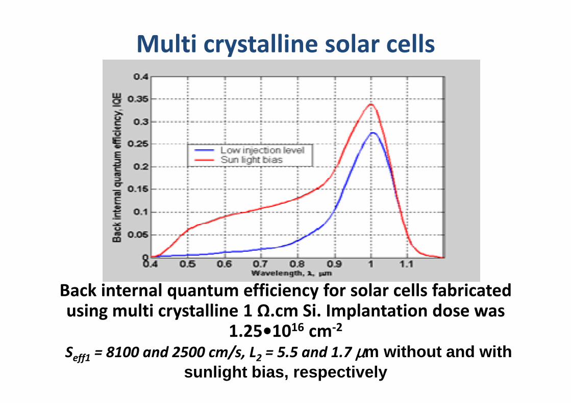
Multi crystalline solar cells
Back internal quantum efficiency for solar cells fabricated using multi crystalline 1 Ω.cm Si. Implantation dose was
1.25•1016 cm-2
Seff1 = 8100 and 2500 cm/s, L2 = 5.5 and 1.7 µµµµm without and with sunlight bias, respectively
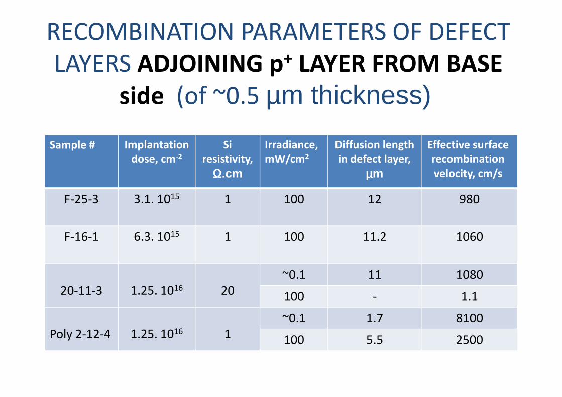
RECOMBINATION PARAMETERS OF DEFECT
LAYERS ADJOINING p+ LAYER FROM BASE
side (of ~0.5 µm thickness)
Effective surface
recombination
velocity, cm/s
Diffusion length
in defect layer,
µµµµm
Irradiance,
mW/cm2
Si
resistivity,
ΩΩΩΩ.cm
Implantation
dose, cm-2
Sample #
9801210013.1. 1015F-25-3 9801210013.1. 1015F-25-3
106011.210016.3. 1015F-16-1
108011~0.1
201.25. 101620-11-3 1.1-100
81001.7~0.1
11.25. 1016Poly 2-12-4 25005.5100
SUMMARY
• Bifacial Si solar cells are able to supply 15-45 % more energy than regular Si cells on LEO space craft.
• The advantages of bifacial Si solar cell are expressed in equivalent efficiency achieving 25 %.
• Technology of space bifacial cells based on the combination of thermal P diffusion for n+ layer doping and B ion implantation thermal P diffusion for n+ layer doping and B ion implantation for p+ layer doping is very promising for fabrication of terrestrial bifacial cells.
• Formation of the defect layer adjoined to BSF should be prevented in fabrication process.
• Ion dose, Si parameters (resistivity, single or multi crystalline) as well as carrier injection level during the measurements are factors affecting the influence of such a layer.