Embed Size (px)
Citation preview

Investigation and Comparison of BZT-Ti6Al4V and
Alumina-Ti6Al4V Brazing for RF Window Application
under High Vacuum Condition
Presentation by
Suresh Beera
12ETMM11
M.Tech
Materials Engineering
SEST, UoH
1/27/2018
Supervisiors :
Dr. Dibakar Das Dr. G. Madhusudhan Reddy
Associate Professor Scientist “G” ,Group Head--MJG
SEST, UoH DMRL, HYDERABAD

CONTENTS
Introduction
Objective
Literature review
Experimental procedure
Result and discussion
Conclusions
References
1/2
7/2
018
2

3
INTRODUCTION
Ceramic materials are inorganic, non-metallic materials made
from compounds of a metal and a non metal.They are formed
by the action of heat and subsequent cooling
Traditional ceramics
Advance ceramics
-Oxides
-Non-oxides
:
Ceramics
Industries are extremely attractive towards engineering ceramics
because of their properties
low density & high hardness,
corrosion and oxidation resistance at elevate temperature
low thermal conductivity, high electrical resistance
low friction, good chemical resistance
exhibit excellent dielectric properties
These materials are brittle and stronger than that of
metals because of their covalent and ionic bonding.

4
Applications of advanced ceramics
Electronic Components
Vacuum tubes
Gas Turbine, Diesel Engines
Nuclear Reactors
Electrical Insulators
Oil drill bit
However, they are relatively
expensive and Ceramics are most
frequently used in conjunction with
other material where joining
becomes a critical issue
tensile force
Ao
Addie
die
Adapted from
Fig. Callister
7e.
The main problems when joining ceramics are miss matches
coefficient of thermal expansion, poor wettability of
ceramics by most metals and alloys. Most of the regular
filler materials do not wet ceramics.

1/2
7/2
018
5
CERAMIC-METAL JOINING PROCESS
These are chosen on the basis of temperature, ease of implementation, functionality .
Among those joining processes, the most adaptable technique is Brazing.

It is a metal-joining process whereby a filler
metal is brought slightly above its melting (liquidus)
temperature (>450°C), but lower than the melting
temperature of the base metal and distributed between
two or more close-fitting parts by capillary action.
It is protected by a suitable atmosphere, usually a flux.
It is similar to soldering different to welding process.
Merits & demerits of brazing process
1/2
7/2
018
6
wettability & contact angle in brazing process
wettability is the capability of solids to build interfaces with liquids.
Wetting is measured in terms of the contact angle.
BRAZING

7
Indirect Brazing (Metallisation) : The ceramic surface is usually coated with a metal
which is suitable to be wetted by a regular filler metal. The metallic coating acts as a
transition material between metal and ceramic. The most widely used method of
metallisation are metalizing by Moly-Manganese Paste process
Direct Brazing(Active Metal Brazing) : This is a single step processes where an active
filler metal is placed between the ceramics & metals and then heated in vacuum. The
reactive metal that is able to form a reaction layer on the ceramic surface that can be
wetted by the conventional filler metal..
Methods to Increase Wettability
Apply surface treatments to the ceramics so that the brazing alloy will wet,
Deposit reactive metal into the brazing alloy that will induce wetting
Advantages of Active metal brazing over
metalizing Route
single step process.
Processing Time is less
It is an economical process
The main drawback is brazed joint
strength is less

Flux & Filler materials for Vacuum Brazing
The filler metal for a particular application is chosen based on its
ability to:
• Wet the base metals
• Withstand the service conditions required.
• Melt at a lower temperature than the base metals or at a very
specific temperature
Filler materials are generally alloys of silver (Ag), gold (Au), copper
(Cu), cobalt (Co) or nickel (Ni). Brazing of non-metallic materials
ceramics and graphite active brazing alloys containing active metals(
Ti, Vor Hf,)are used
1/2
7/2
018
8
Brazing operation takes place either in a controlled atmosphere, such as nitrogen
or argon, or a vacuum better than 10-3N.m-2

9
In the framework of thermonuclear fusion
reactor, RF power is used to heat the plasma and
accelerate particles in order to drive steady state
currents in the plasma.
Radio frequency windows, used in transmission
lines of the Tokamak reactor, are one of the
critical components limiting the power that can be
coupled with the plasma current into the reactor.
The critical functions of RF window are to act as
temperature barrier, vacuum barrier and to be
transparent to RF power with minimal losses.
The window failures are thought to be due to
multipacting and material imperfection.64 Waveguide RF Window
Schematic view of In-vessel LHCD
system on SST 1 Tokamak
The most common material used for RF windows is high purity
polycrystalline alumina and the frame is made of Ti6Al4V alloy.
RF window in Tokamak fusion reactor

Barium Zinc Tantalate (BZT)ceramics
Large dielectric constant
High quality factor(low dielectric loss) at the microwave frequency.
low temperature coefficient of resonant frequency
1/2
7/2
018
10
Radio frequency (RF) window sections require high mechanical strength along
with excellent microwave dielectric properties which are exhibits in Perovskite
ceramics Barium Zinc Tantalate (BZT.)
Therefore we can develop a BZT ceramic considered as an alternative dielectric
material for high power RF window application
Applications of BZT ceramics
Dielectric resonator
Microwave telecommunication
In satellite broadcasting
In mobile phone base stations

LITERATURE REVIEW
1/2
7/2
018
11
12
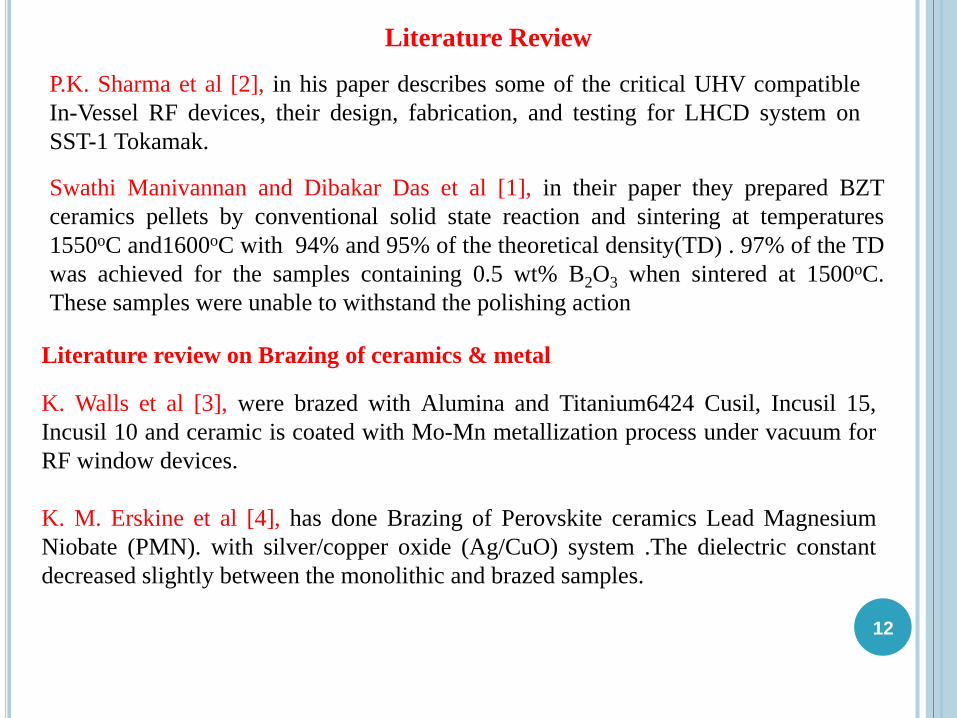
P.K. Sharma et al [2], in his paper describes some of the critical UHV compatible
In-Vessel RF devices, their design, fabrication, and testing for LHCD system on
SST-1 Tokamak.
Swathi Manivannan and Dibakar Das et al [1], in their paper they prepared BZT
ceramics pellets by conventional solid state reaction and sintering at temperatures
1550oC and1600oC with 94% and 95% of the theoretical density(TD) . 97% of the TD
was achieved for the samples containing 0.5 wt% B2O3 when sintered at 1500oC.
These samples were unable to withstand the polishing action
Literature Review
K. Walls et al [3], were brazed with Alumina and Titanium6424 Cusil, Incusil 15,
Incusil 10 and ceramic is coated with Mo-Mn metallization process under vacuum for
RF window devices.
K. M. Erskine et al [4], has done Brazing of Perovskite ceramics Lead Magnesium
Niobate (PMN). with silver/copper oxide (Ag/CuO) system .The dielectric constant
decreased slightly between the monolithic and brazed samples.
Literature review on Brazing of ceramics & metal

13
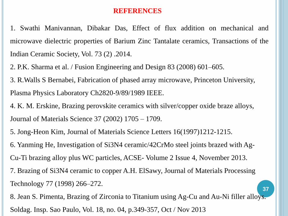
Jong-Heon Kim et al [5], Alumina brazed with Ag-Cu-Zr alloy, and the brazing alloy
interface was identified as single ZrO2 layer.. The fracture shear strength was strongly
influence by morphology of the joint, which was related to ductility of the joint.
Yanming He et al [6],in their paper discussed with Ag-Cu-Ti+WC composite filler was
employed for the joining of Si3N4 ceramic and 42CrMo steel, with increasing in the
content of WC particle, was gradually decreasing. the thickness of reaction layer and
increase in the flexural joint strength over the Ag-Cu-Ti brazing alloy
A.H. ElSawy et al [7], has done Brazing of Si3N4 to Cu using Cusil-ABA. The shear
strength of the brazed joints increased substantially as a result of applying a light load
on the joints during brazing and fine surface finish of copper base-metal
Jean S. Piment et al [8] reported on brazing with Zirconia and Titanium metal using
non active eutectic Ag-28Cu filler alloy. Titanium diffusion from the metallic
counterpart to the ceramic surface produced sound brazing joints.
Literature Review

OBJECTIVE OF THE WORK1/2
7/2
018
14
The current study is to prepare a BZT ceramic by conventional solid state
method.
To develop a brazing procedure with a suitable filler materials and that
provides a high quality hermetic seal between BZT –Ti6Al4V alloy that
withstand operating temperature up to 250°C, under vacuum with a
differential pressure of 3 bar.
Technical approach
BZT was brazed with Ti6Al4V using active and non active brazing alloy of Ag-Cu
alloys. Ticusil® (4.5%Ti) Cusil-ABA® (1.5%Ti), BAg8 were brazed under high
vacuum.
Optical microscopy, Scanning Electron Microscopy, Dispersive Energy
Spectroscopy (SEM-EDS), and Electron Probe Micro Analyser(EPMA) were
characterised in order to study the interface of brazed joints.
Using universal testing machine, Shear strength of the brazed sample were carried
out.
For comparison study, alumina is also brazed with Bag8

15
Experimental Procedure

16
Preparation of Barium Zinc Tantalate Ba(Zn0.33Ta0.67)O3 Ceramic Pellet -Solid
State Method
BZT powder
Green pellet
Sintered pellet
1 inch X 1 inch size square pellets (25.4 X25.4 X4 mm) 97-98% of (Theoretical
Density-TD).Density of BZT- 7.92 g/cc

17
Chemical compounds Al2O3 SiO2 MgO Na2O Fe2O3 CaO
Wt% 99.7% 0.05 0.08 0.03 0.015 0.03
Moreover to study the effect of ceramic on the brazed joint strength, commercially
available Alumina plates (97-98% of TD) with the same dimension as that of BZT
pellet were used for brazing. The nominal chemical composition of alumina is as
follows
Eleme
nt
Titaniu
m
Aluminiu
m
Vanadiu
m
Carb
on
Iro
n
Oxyg
en
Nitrog
en
Hydrog
en
Wt% 89.707 6 4 0.03 0.1 0.15 0.01 0.003
Chemical Specification of Ti6Al4V alloy
Ti6Al4V alloy is commercially available and its chemical composition as follows
Alumina Plate
Prior to brazing process all polished samples were cleaned by acid pickling
process to remove the surface impurities, tough deposits of scale and oxides.

1818
Brazing filler
alloy
% copper in
alloy
% silver in
alloy
%titanium in
alloy
Ticusil 26.7 68.3 4.5%
Cusil-ABA 35.25 63 1.75%
BAg8 28 72 nil
Brazing Filler alloy Composition
Thickness of filler material (foil) is around 100-130 μm
Eutectic Cu-Ag alloy used in ceramic brazing
-chemically inert & ductile
-reduces the oxidation behavior at the interface
-minimize residual stress during cooling at the end of the joining
process
Cu-Ag Brazing Filler Material
A normal load was applied to the assembly on
each joint to avoid eventual misalignments.
Brazed joint of ceramics and TI6Al4V alloy

Comparison
Active Brazing
Alloy
Ag-Cu
(BAg8)
TiCuSilCuSil-ABA
Ceramics (BZT) &
Ti alloy (Ti-6Al-4V)Ceramics (Al2O3) &
Ti alloy(Ti-6Al-4V)
BRAZING
Ag-Cu
(BAg8)
19
Flowchart of Brazing operation on various filler alloy with Ti6Al4V
alloy
Brazed joint of ceramics

20
Brazing Process in Vacuum Brazing Furnace
20
S.No Ceramics Base
material
Filler
Material
Brazing
Temperature
Soaking
Time
(min.)
1 BZT Ti-6Al-4V Ticusil 8500 C 30
2 BZT Ti-6Al-4V Cusil-ABA 8500 C 30
3 BZT Ti-6Al-4V BAg8 8300 C 30
4 Al2O3 Ti-6Al-4V BAg8 8300 C 30
During brazing process The assembly is maintained vacuum pressure of
1.5 x10⁻⁵ to 3 x10⁻⁵ mbar.

21
Square Threaded PlungerFixture assembly for shear strength
Shear Test using Universal Testing Machine
UTM-Walter-baiag
Shear strength-τ MPa
Load –F kN
Brazed Area-A mm2
Initial load of 0.05kN is applied with a cross
head speed of 0.1 mm/min.
All dimension are in mm
Brazed lap joint of ceramics -TI6Al4V alloy

22
Shear Testing with Brazed Lap Joint

23
Characterization Techniques

24
Scanning Electron Microscope Equipment
Electron Probe Micro Analyzer Equipment
Inverted Olympus Optical Microscope

25
Results and discussion

26
26
Figure 1 Optical Micrographs of BZT-Ti6Al4V-TiCuSil Figure 2 Optical Micrographs of BZT-Ti6Al4V-CuSil ABA
Figure 3 optical Micrographs of BZT-Ti6Al4V-BAg8 Figure 4 Optical Micrographs of alumina -Ti6Al4V-BAg8
The joints are free of interfacial
micro defects, and exhibit excellent
physical contact and good
metallurgical bonding with high
diffusivity.
Ceramic FillerReaction
Zone (µm)
Ceramic-
filler (µm)
Filler-base
metal (µm)
BZT Ticusil 90 9 25
BZT Cusil-ABA 80 5 30
BZT BAg8 120 25 48
Al2O3 BAg8 100 24 50
Optical Micrographs of Brazed JointTable Thickness layer of various brazed joints

27
EDS % WT of Brazed JointBZT-Ti6Al4V-TiCuSil BZT-Ti6Al4V-CuSil ABA
Element
spot 1 spot 2 spot 3 spot4 spot 5
Element
spot 1 spot 2 spot 3 spot4 spot 5
Weight% Weight% Weight% Weight% Weight% Weight% Weight% Weight% Weight% Weight%Ti K 49.12 34.66 8.1 34.57 32.11 Ti K 4.38 44.59 33.95 43.44 66.59
Cu L 41.92 45.43 14.66 47.13 42.73 Cu L 12.07 44.88 0 45.83 29.48
Ag L 0 19.91 77.23 18.3 21.11 Ag L 83.55 6.05 20.52 10.73 3.94
O K 8.96 0 0 0 4.04 O K 0 4.48 45.53 0 0Totals 100 100 100 100 100 Totals 100 100 100 100 100
BZT-Ti6Al4V-BAg8 ALUMINA-Ti6Al4V-BAg8
Element
spot 1 spot 2 spot 3 spot4 spot 5
Element
spot 1 spot 2 spot 3 spot4 spot 5
Weight% Weight% Weight% Weight% Weight% Weight% Weight% Weight% Weight% Weight%Ti K 28.51 6.69 43.34 46.05 32.26 Ti K 19.65 16.44 28.52 43.77 29.97
Cu L 57.13 11.98 15.64 37.18 63.84 Cu L 54.93 67.32 68.13 46.14 0Ag L 14.35 73.18 28.36 5.8 3.9 Ag L 25.42 16.23 3.35 0 70.03
O K 0 8.15 12.66 10.98 0 O K 0 0 0 10.09 0Totals 100 100 100 100 100 Totals 100 100 100 100 100
Element Composition at the Interface of the Brazed Joint with SEM-EDSFigure Brazed joint with EDS spectrum and SEM-SE Micrograph

28
Electron Probe Micro Analyzer
Elemental Mapping & Line Scan analysis between brazed interface

29
EPMA- Mapping & Line analysis of BZT-
Ti6Al4V-Ticusil
EPMA-Elemental Mapping of BZT-Ti6Al4V-Ticusil
EPMA-Line scan analysis of BZT-Ti6Al4V-Ticusil
2 1

30
EPMA-Elemental Mapping of BZT-Ti6Al4V-Ticusil
1 2
EPMA-Line Scan analysis of BZT-Ti6Al4V-CusilABA
EPMA- Mapping & Line analysis of BZT-
Ti6Al4V-Cusil ABA

31
EPMA-Elemental Mapping of BZT-Ti6Al4V-BAg8
EPMA-Line Scan analysis of BZT-Ti6Al4V-BAg8
2
EPMA- Mapping & Line analysis of BZT-
Ti6Al4V-BAg8
1

32
1 2
EPMA- Mapping & Line analysis of
Alumina-Ti6Al4V-BAg8
Figure EPMA-Elemental Mapping of Alumina-Ti6Al4V-BAg8
EPMA-Line Scan analysis of Alumina-Ti6Al4V-BAg8

S.No Brazed Sample Id Length(mm) Breath(mm) Max
Load(kN)
Shear
Strength(MPa)
1(a) BZT-Ti64-TiCuSil(4.5%Ti) 25.10 15 12.12 32
1(b) BZT-Ti64-TiCuSil(4.5%Ti) 24.5 15 12.13 33
1(c) BZT-Ti64-TiCuSil(4.5%Ti) 22.8 13.5 10.41 34
2(a) BZT-Ti64-CuSilABA(1.75%Ti) 24.5 14.3 10.52 30
2(b) BZT-Ti64-CuSilABA(1.75%Ti) 22.85 12.6 8.9 31
2(c) BZT-Ti64-CuSilABA(1.75%Ti) 25 15 11.98 32
3(a) BZT-Ti64-Bag8(72ag) 23.15 15.3 16.20 46
3(b) BZT-Ti64-Bag8(72ag) 22.7 15.5 15.90 45
3(c) BZT-Ti64-Bag8(72ag) 22.8 15.5 15.90 45
4(a) Al203-Ti64-Bag8(72ag) 25.1 14.9 16.74 45
4(b) Al203-Ti64-Bag8(72ag) 25.1 14.6 15.91 43.5
4(c) Al203-Ti64-Bag8(72ag) 25.1 15.6 17.23 44
33
Shear Strength calculation of the Brazed Joint
In Ticusil, Cusil-ABA, the excess amount of Titanium (due to base & filler material)
leads to brittle joint, forming an inter-metallic compounds at the brazed interface thereby
strength has decreased

34
Brazed sample of Ticusil, BZT & Ti-6Al-4V alloy Brazed sample of CuSil-ABA , BZT & Ti-6Al-4V
alloy
Partial Failure is on ceramic region and remaining is between ceramics & filler material
In a ceramic brazed joint, the base material and ceramic components
experience tensile and compressive residual stresses. The maximum thermal
residual stress appeared in the ceramic region adjacent to the ceramic/filler
interface
Fracture Surface of Active Brazed Joint( Ticusil, Cusil-ABA)

35
Fracture Surface of (BAg8) Non Active Brazed Joint
35
Brazed sample of BZT & Ti-6Al-4V alloy
complete fracture is on ceramics side only
Brazed Sample Of Alumina & Ti-6al-4v Alloy

36
BZT pellets are prepared by solid state reaction with a maximum of 97~
98% Theoretical Density (TD) respectively.
Brazing of BZT and Ti-6Al-4V was carried out with active (Ticusil,
Cusil-ABA) and non active (BAg8) brazing alloy. Alumina-Ti6Al4V is
successfully brazed with BAg8.
Titanium layer is distributed between ceramic and brazing alloy along
the brazed joints. the presence of Titanium enhance more wettability for
getting sound brazed joints.
Non active brazing alloy (BAg8) exhibits more shear strength (~45MPa)
when compared to active brazing alloy, since reaction layer thickness
(∼25μm) is more in BAg8.
Visual observation of fracture surface of shear strength test samples of
brazed joints indicates, complete fracture were observed in ceramic side
in case of BAg8 (non active filler alloy) brazed joints, where as partial
fracture was noticed in ceramic side of Ticusil, Cusil-ABA (active filler
alloy) brazed joints.
CONCLUSION
37
1. Swathi Manivannan, Dibakar Das, Effect of flux addition on mechanical and
microwave dielectric properties of Barium Zinc Tantalate ceramics, Transactions of the
Indian Ceramic Society, Vol. 73 (2) .2014.
2. P.K. Sharma et al. / Fusion Engineering and Design 83 (2008) 601–605.
3. R.Walls S Bernabei, Fabrication of phased array microwave, Princeton University,
Plasma Physics Laboratory Ch2820-9/89/1989 IEEE.
4. K. M. Erskine, Brazing perovskite ceramics with silver/copper oxide braze alloys,
Journal of Materials Science 37 (2002) 1705 – 1709.
5. Jong-Heon Kim, Journal of Materials Science Letters 16(1997)1212-1215.
6. Yanming He, Investigation of Si3N4 ceramic/42CrMo steel joints brazed with Ag-
Cu-Ti brazing alloy plus WC particles, ACSE- Volume 2 Issue 4, November 2013.
7. Brazing of Si3N4 ceramic to copper A.H. ElSawy, Journal of Materials Processing
Technology 77 (1998) 266–272.
8. Jean S. Pimenta, Brazing of Zirconia to Titanium using Ag-Cu and Au-Ni filler alloys.
Soldag. Insp. Sao Paulo, Vol. 18, no. 04, p.349-357, Oct / Nov 2013
REFERENCES

9.Humpston & Jacobson, Principles of Soldering and Brazing 1993.
10. Brazing ,joining process of ceramic picture - Wikipedia, the free encyclopedia.
11. An introduction to brazing, Sulzer metco, August-2011.
12.C.Ferro A.Orsini, Multiple brazing of ceramic windows to a single flange491,Fusion
Technology 1992.
13.Review Advances in brazing of ceramics O. M. Akselsen . Journal Of Materials
Science 27 (1992) 1989 2000.
14.Brazing of Si3N+ ceramic to copper A.H. ElSawy, Journal of Materials Processing
Technology 77 (1998) 266–272.
15.Victor A. Green hut, Metal-Ceramic joining, the Minerals, Metals & Materials
Society, 1991, 104-119.
16.Welding Hand Book, 8th Edition Vol. 3, 390-416
17. Markku Ainali, the Cuprobraze brazing Handbook Edition Nr 8, September 2006.
18.The CuproBraze brazing handbook, Edition Nr 8, September 2006
1/2
7/2
018
38
REFERENCES

27-01-2018
39
University of Hyderabad
Dr. Dibakar Das,
Associate Professor , SEST
Prof.Rajender Singh,
Dean, SEST
Prof. M. Sundararaman, former Dean,
and other faculty of SEST
Mr Mallesh, Smt.M. Padma, Mr Venu,
Mr Venkat Ramana and
other staff members of SEST
ACKNOWLEDGEMENTS
DMRL,HYD
Dr. G. Madhusudhan Reddy, Sci- “G
Dr.Amola Gokhale, Outstanding Sci, Director
Mr. Amit Singh Sci-“D”,
Mr. Ramdas
I express my gratitude towards
Mr. Vamsi Krishna R, Mrs. Swathi M,
Paul, Y.Pardhu, K.V.Sreenivasulu,
Vijay , Sunil, Vinitha, my friends,
classmates, students of SEST in UoH
My parents DhanaRaju Beera, Smt. Pusphavathi and
my family members for their financial support, strong
motivation and constant encouragement during the
course of my project work

40
1/2
7/2
018
40
Thank you for kind attention
-Suresh Beera