Embed Size (px)
Citation preview

artisan
Hydraulic Swing Arm
Die Cutting Press
“Clicker”
TAIWEI MODEL
A-TW-520 C
F-45
Made in China

Clicking press instruction manual
CONTENTS
Guarantee conditions · · · · · · · · · · · · · · · · · · · · · .. · · .. · ... · ................................ : . . . . . . . . . . . . . . . . . . . . . . Page 1
General information · · · · · · · · · · · · · .. · · · · · .. · · · ·.......................................................... Page 1
Identification of the machine · · · · · · · · · · · · · · · · .... · · ....... · ·. . . . . . . .. . . . . . . . . . . . . . . . . . .. . . . . . . . . . . . . . . . . Page 2
Distance to be left free · · · · · · · · · · · · · · · · · · · · · · · · · · · · · · ..... · · · · ..... ·. · ... · ....... · · .............. ·.. . . . . Page 2
General safety regulations · · · · · · · · · · · · · · ·. · · · · . · .. · · · .... · · · ·.. . . . . . . . . . . . . . . . . . . . . . . . . . . . . . . . . . . . . . . . . . Page 3
Transport and handling · · · · · · · · · · · · · · .... . ·.... .. ....................................................... Page4-5
Preliminary control checks · · · · · · · · · · · · · .. · · · ·. . . . . . . . . . . . . . . . . . . . . . . . . . . . . . . . . . . . . . . . . . . . . . . . . . . . . . . . . . . Page 6
Machine start-up and stop · · · · · · · · · · · · · · · · · · · · · · · · · · · · · · · · · · · · · .. · · · · · · .. · · · ·. · · · · · · · · · .. · · · · · · · · · · · · · · · Page 6
Adjustinent setting controls · · · · · · · · · · · · · · · · · · · · · · · · · · · · · · · · · · · · · · · · · · · · · · · · · · · · · · · · · · · · · · · · · · · · · · · · · · · · · · Page 7
Cutting force adjustment · · · · · · · · · · · · · · · · · · · · · · · · · ... · · .. · · ..... · ............. .................. ·. · · ·. · · ·. Page 8
Die cutting instructions · · · · · · · · · · · . · · · · · · · · · · · .... · ....... · · · ....... · .... · · · ..... · · · · .... · · · · · · · · · · · · · · · Page 8
Clicking press maintenance · · · · · · · · · · · · · · · · · · · · · .. .. · · · · · ·. · · .. · .... · ............... · .......... · · · · · · · · · · Page9-10
Troubleshooting-identification instructions · · ·· · ··· ·· · ·· · ·· · ··· · · ·· · ·· · ·· · · ·· ··· ··· · ·· · ·· · ·· · ·· · ···· Pagell-12
Machine parts subject to wear · · · · · · · · · · · · · · · · · ·. · · · · · · · · · · .. · · · · · · .... · · · ·. · ...... · ........ · · · · · · · · · · Page, 13
Spare parts · · · · · · · · · · · · · · · · · · · · · · · · · · · · · · · · · · · · · · · · ·. · . ... . ... · . .. .. ·. · · . · · · .. · · · · · · · .... · · · · · ...... · · · · · · · · · · Page 13
Optional accessories · · · · · · · · · · · · · · · · · · · · · · · · · · · · · · · · · · · · · · · · · · · · · · · · · . · · · · · · · · · · · · · · · · · · · · · · · · · · · · · · · · · · · · · Page 13
Technical information ·· ···· ····· ... ····· ...... . ...... . ....... . ...... . . ...... ·· · .......... ················ Page 14
Machine measurements · · · · · ... · · · .. · .. . . · · ...... ...... . .. .... · .......... · · · ·. · · · .. · · · · · · · · · · · · · · · · · · · · · Page 15
Hydraulic oil layout · · · · · · · · · · · .. · · · · .................... : ....................................... · · · · · · · · · · Page 16
Hydraulic oil distribution · · · · ... · . · .. · .... · ............... ...... · . · ... .... · .......... · · · ·. · · · · · · · · · · · · · · · · Page 17
Machine base ..... _ ......................... .. ....................... . ........................................ Page 18
Swing beam group · · · · · · · · · · · · ............. . ................................ · .... · ... ·. · · · · · · .. · ·. · · · · · · · · · · Page 19
Piston-cylinder group · · · · · · · · ... · ....... . ...................... · .......... · · · . · ..... · · · · · · · · · · · · · · · · · · · · · ~age 20
Electrical layout · · · · · · · · · · · · · · · · · · · · · · · · · · · · · · · · · · · · · · .. · · · · · · · · · · · · · · · · · · · · · · · · · · · · · · · · · · · · · · · · · · · · · · · · · · · · · Page 21

Clicking press instruction manual Page 1
MACHINE GUARANTEE.
The Company undertakes to supply machinery which is free of any faulty parts which can compromise the perfonnance and use for which the machine was designed. It will not be held responsible for any faulty electrical or electronic parts, or for any parts which deteriorate due to nonnal wear and machine use such as gaskets and seals, fuses, microswitches, etc.
Tue Vendor will not be held responsible for any damage caused by use not included in the instructions in this manual, or caused by negligence or incorrect use. The company will also not be held responsible for any unauthorised modifications or changes made to the machine by the purchaser, who then becomes responsible for the machine.
The machine is delivered to the customer already tested.
This machine is covered by a six month guarantee. All parts replaced during the guarantee period are covered by the guarantee until the expiry of the machine guarantee. To benefit from the guarantee comditions, the purchaser must inform the manufacturer of any faulty parts or construction in writing , within 10 days of the discovery and accurate testing of the machine. He must also agree to reasonable control checks by the vendor, and return the faulty parts which are the source of complaint, to the manufacturer, if requested.
After receiving the complaint from the purchaser, the vendor will, at his own expense, provide for one of the following:
a)replace the faulty part b )have the replacement made by a third party
Where the fault is the responsibility of the vendor, any damages paid to cover expenses cannot exceed the sum equivalent to items a and b, described above.
The replacement will be delivered ex works from the manufacturer' s plant. If any intervention by a
technician is necessary, all rosts will be invoiced.
The machine measurements and technical date included in this manual are not binding, and can be updated at any time without prior notice from the manufacturer.
GENERAL INFORMA T/ON.
Before using the machine, please take care to read all the instructions included in this manual, as well as the information included on the plate attached to the machine. This instruction manual has been drawn up for the customer's information, and is considered as part of the machine, in the same manner as any mechanical, pneumatic or electrical part. Therefore, for obvious reasons, please keep the manual near the machine, on hand for easy reference at all times.
Before any work or maintenance operations, the machine must be disconnected from the main electricity line. The Constructor will not be held responsible if these rules and precautions are not followed .scrupulously.
The machine is equipped with all the protection guards necessary for safeguarding the operator while working on the machine; the protection systems must never be removed except for maintenance operations. Before beginning any type of work on the machine the operator must wear all the necessary types of protective clothing suitable for the job in hand.
Page 2
MACHINE /DENT/FICA TION.
The plate attached to the machine provides the . following information:
• machine range
• machine model
• serial number
• voltage motor pump
voltage connection motor pump
Clicking press instruction manual
It is strictly forbidden to remove change or alter the information provided on the identification plate. If the seal should be accidentally damaged, the customer must inform the manufacturer immediately.
When the machine is delivered, please control that all parts correspond with the customer s order, and that no machine parts have been damaged druing transport. If the machine has suffered any damage, please contact the manufacturer or the transport company immediately.
When requesting information or service assistance, always quote the serial n° and the year of construction of the machine.
Before connecting the machine to the current, check that the main line voltage is the same as that shown on the machine plate: If it should be necessary to change the voltage of the carriage and pump motors, the voltage must also be changed at the transformer so that all electrical equipment on the machine is connected to the correct voltage.
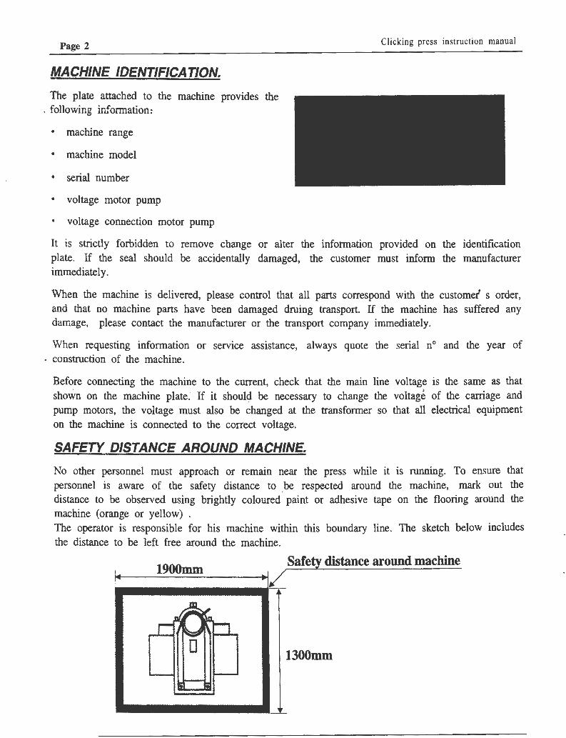
SAFETY DISTANCE AROUND MACHINE.
No other personnel must approach or remain near the press while it is running. To ensure that personnel is aware of the safety distance to be respected around the machine, mark out the distance to be observed using brightly coloured· paint or adhesive tape on the flooring around the machine (orange or yellow) . The operator is · responsible for his machine within this boundary line. The sketch below includes the distance to be left free around the machine.
1900mm Safety distance around machine ----/
1300mm

Clicking press instruction manual Page 3
GENERAL SAFETY REGULATIONS. Before starting up the machine, or carrying out any maintenance operations, it is essential that the chapters relative to each operation be read carefully; in particular, please read transport and handling instructions, ' connection to main electrical supply, and use and maintenance instructions with care.
In order to safeguard the operators working on the machine from any injury, please ensure that personnel obey all the safety instructions provided below with the utmost care: -
• No other personnel must approach or remain near the press while it is running.
• When the press is running, never place the hands between the cutting plate and the mobile arm (for example: in order to change die position) . This must also be observed while the machine is teing switched off, since the oil pressure which supports the mobile arm will be released and the press head will descend.
• Never wear clothing or jewellery which can provoke a risk of injury when working on tbe machine (e.g.: wide or flapping clothing, scarves, ties, or wide cuffed sleeves) .
• Never place any tools or other objects not directly used for the work in hand on the cutting plate or the mobile arm. Vessels containing liquid or beverages can spill into the electrical box causing severe electrical shock.
• All interventions for adjustment settings and maintenance must be carried out by qualified personnel and only after the machine has been disconnected from the main line current.
• Never remove the labels attached to the machine and always respect the warmings printed on these labels: If they are damaged in any way, the labels must be replaced for safety reasons.
• Never change or modify any of the protective covers or shields on the machine (protective panels, end-of-stroke blocks, pressure switches, etc.) nor any of the safety devices provided to protect the operator from injury. It is severely forbidden to tamper with the electrical installation or modify it in any way without the permission of the manufacturer. If these ins~ctions are not followed as described, the machine is no longer covered by the guarantee. All results from lack of respect of these regulations and standards (machine damage, injury to personnel, ete.) will be the total responsibility of the customer.
• To clean the machine, never use strong water jets, solvents, gasoline, or any type of corrosive substance. Use only soft cloths soaked in detergent liquid, and when cleaning the electrical command panel, use a brush to remove the dust from the less accessible areas.
• When carrying out machine maintenance, warn all personnel not to use the machine.While maintenance operations are underway, and whenever the press is being used, the operator must always remain near the machine.
• When any machine components need replacing, request original spare parts from the manufacturer or from the authorised sales agent.
This press has been designed and built for die cutting flexible and semi-rigid materials. Never . attempt to cut other types of material on this machine such as:metal, wood, hard plastics, bakelite, or any materials containing toxic waste or ''ust such as asbestos. Take care to check that the interior of the material to be cut does not ·;ontain metal meshing or similar, which will not only damage the dies, bur also cause violent splinter flying.
This press has not been designed for cutting materials for foodstuffs or medical use, or for other uses not specified in this manual.

Page 4 Clicking press instruction manual
TRANSPORT AND HANDLING.
All the transit and installation area, plus the transport vehjcle area must be carefully inspected before handling to ensure they are well clear of all objects and personnel. All obstacles must be removed before handling.
According to the transport request made by the customer, the machine is delivered on a pallet and covered with protective plastic film, or in an open or closed wooden case or crate. The plastic film will only protect the machine from damp and dust during transport: it cannot protect the machine against banging during handling operations. The press is bolted to the pallet or to the crate base in three points.
The machine can be safely handled and moved on the ground using a fork lift adequate for the machine weight (refer to the technical information paragraph) .
Clicking press on pallet
If the press to be raised is attached only to a pallet, the hoisting chains or cables must be attached to the eyeblots (Fig.I) Never raise the machine ~y passing ropes or slinging straps around the mobile arm as this will damage the internal components, as well as leading to arm rotation, causing load oscillation which cannot be controlled and which provokes a serious danger for machine and personnel. Proceed slowly when beginning the initial raising operation to maintain the press in equilibrium without banging or swaying. Make sure that all personnel not directly involved in the manoeuvres are kept well clear of the area.
Never remove the safety block until the machine has been safely placed in its final pofition. This block
stops the mobile arm from rotating during handling operations.
Fig. 1
' : .,
Safety block
D • • Eyebolt
Pallet attachment
Pallet
m

Clicking press instruction manual Pag~ 5
TRANSPORT AND HANDLING.
(CONTINUED FROM PREVIOUS PAGE)
Press in wooden case or crate.
Whether the press is packed in an open or closed crate or packing case, it must be raised using chains or cables which are adequate for the combined weights of machine and case (See paragraph TECHNICAL INFORMATION) . The chains or cables must be passed under the packing crate in the points shown by the arrows in the drawing (Fig.2) . To place the press in position, proceed as follows:
1) Remove the packing crate and the plastic protective film. 2) Remove the three bolts which attach the press feet to the pallet (Fig. 1) .
3) Raise the press by hooking up to the eyebolts (Fig 1) , remove the pallet and place the press on a fork lift to transport it to its final position.
4)
Before placing the press in position, check that the floor is level, and clean of all oil or viscous liquids. The machine does not need bolting to the floor; where necessary, it is sufficient to insert rubber squares between the feet and the flooring. The squares must have the correct degree of elasticity: if they are too soft the weight of the machine will flatten them and they will loose their absorbing effect; if they are too hard, the machine will slip
Now the press can f placed in position.
Fig. 2
POINT FOR PASSING CHAINS/CABLES

Page 6
PRELIMINARY CONTROL CHECKS
In order to check on any damage the machine may have
suffered during transport, control the condition of the press commands (at least from the outside) and check for any oil leakage.
Before connecting the machine to the main line, check that the voltage is the same as that of the machine printed on the plate attached to the electrical box. If the voltage or frequency is different from that of the main line, ask advice from the manufacturer or the sales agent.
A TTfNT/ON!According to the agreement made with the customer, the press can be delivered with or without the hydraulic oil load. Never start the machine until the oil level has been carefully checked to be sure it is correct for machine function. The oil tank is filled through the opening on the left hand side of the press (Fig. 1) after removal of the protection shield. Pour the hydraulic oil into the tank till it reaches a level of about 3 centimetres under the lip of the openting.
Clicking press instruction manual
Fig. I
Oil level-30mm f
(See paragraph TECHNICAL INFORMATION for the type of oil to be used.) i>o not open the right
hand side cap as this will empty the oil in the tank.
MACHINE STOP AND START UP.
To start up the machine, tum the ignition switch I to position "I" (Fig. 2) . If the mobile arm rises, the rotation direction is correct, if the arm does not rise, the electrical phase wires must be inverted. The motor should turn in an anticlockwise direction. ·
To stop the machine tum the switch I to " O" position. The motor takes about I minute to stop completely. After this time, the arm will start to descend slowly.
During the descent of the mobile arm, keep hands well clear of the machine to avoid crushing between the arm and the cutting plate.
II
Fig. 2
• t
1

Clicking press insfruction manual
ADJUSTMENT SETTING CONTROLS.
l) Start up switch. 2) Signal led: machine ON. 3) Right hand push button. 4) Left hand push button.* 5) Handwheel for setting height. 6) Pressure steeing. * 7) Cutting method switch
*Optional: programmable push button paneL
When the switch (1) , is turned to "I" position, the motor will start up and the signal led ( 2)
will light up. When motor rotation has reached its maximum rate, the mobile arm will rise to the_ height previously set using the handwheel (5) :
CLOCKWISE DIRECTION: The arm will be lowered
ANTICLOCKWISE DIRECTION: The arm will be raised.
Page 7
Fig. l
II
' Do not force handwheei rotation at ·the end of either setting to avoid damaging the mechanism. When the arm is being lowered, keep hands well chear of the machine to avoid crushing between the arm and the cutting plate.
When the arm is raised in work position, it can be rotated both to the left and right, using the two knobs which contain the two push-buttons that control the die cutting action. This is a twohanded conrtol system; both buttons must be pressed at the same time to lower the mobile arm . If the buttons are pressed with a difference of more than three tenths of a second, the lowering action is deactivated. It is impossible to activate the press using a single button.
The release of one or both buttons will provoke the arrest of the descent action and the return of the arm to its work position, otherwise the arm down stroke will finish at the dies.
When the work cycle on the press is completed, tum the switch (1) back to "O" position, and do not leave the machine unattended until the arm has returned to its rest position.

Page 8 Clicking press instruction manual
CUTTING FORCE ADJUSTMENT. According to the agreement made with the customer, the press can be equipped with a standard press button panel with a single cutting force setting, or with an optional panel that can be programmed for three settings.
Single setting control panel
Turn the index of knob 3 ( Fig. l) in a clockwise direction to obtain a gradual increase in cutting stroke force. The cutting force used must be in proportion with the size of the die and the type of material to be cut.
Programmable panel
The programmable control button panel ( optional,Fig2) permits three different cutting force settings, adjustable using the regulators Rl , R2, and R3, and able to be recalled using the corresponding button Pl, P2, or P3. This device is · located on the left hand handle in place of the single press-button.
Cutting method switch.
Switch n° 7 is used to select the cutting method for use on the machine:
P2
~ Pressure gauge cut; the pressure is activated as soon as the beam comes into contact with the cutting die.
\J Timer cut; the pressure is automatically set on maximum value 6 by the electronic card; the beam descent time is set by
adjusting the potentiometer pressure. When this period is completed the beam returns to its original positions.
DIE CUTTING INSTRUCTIONS.
Fig. 1
1
single setting control panel Fig. 2
1) Tum the main switch (1) to start up the press; the arm will rise. 2) Select the cutting method (pressostate or timer) . 3) Move the arm to one side to leave the cutting plate free, spread the material to be cut,
and place the dies on top of the material. 4) Tum the arm so that it covers the whole die ; tum the handwheel (2 ) in a clockwise
direction to bring the arm down to 8 mm from the die. 5) Set the cutting pressure or cutting time using command(3), according to the type of cutting die or
material to be cut. 6) Press buttons Pl and P2 at the same time to command cutting action. 7) After the cutting action, the arm will rise; move the arm to one side in order to remove the cut rilaterial. Programmable panel
The cutt.ing action is the same as the single setting function except that button Pl must be pressed at the same time as one of the three buttons P2, P3, and P4 according to the respective values programmed on the potentiometers R2, R3 , and R4.
In both cases, make sure that the arm stroke hits the centre of the die during the cutting action to prevent all danger of the die spitting out and causing serious injury.

Clicking press instruction manual
CLICKING PRESS MAINTENANCE INSTRUCTIONS.
In order to preserve the working life and efficiency of the machine, certain regular maintenance operations must be carried out as follows:
The cutting block (Fig. 1) must be turned upside down every six working days to provide uniform wear. When a hollow of approximately 2 mm is formed, the block must be planed fiat.
The aluminium plate (Fig. 1) attached to the arm
must be rotated 180° at least every two months of machine work life, to make Wear as uniform as possible and to maintain the plate reasonably flat.
During die cutting operations, dust is formed by the cut material. This dust deposits on the seal ring (Fig. 1) of the column. With time, this dust forms a sponge effect, absorbing the oil on the column, depositing a coat of oil on the seal ring similar to an oil leak. The area around the ring must be cleaned once a mouth.
Dust left on the hand has a tendency to accumulate in the cutting action control buttons (Fig. 2) . hi spite of their self-cleaning action, these buttons can block if left for long periods, with the danger of blocking the machine action. To clean the inside of the button, press a piece of adhesive tape onto the button, pull .the command rod upwards so that the dust can be cleaned ( better still if a strong air blast with compressed aii is used) .
Dust and small cut material waste penetrate in the air vents to the motor and under the base of the press at floor level ( Fig. 2) where they deposit blocking the motor cooling air circulation, risking electrical motor overheating and burning. At least every six months clean inside the motor area carefully, after removing the front protection shield.
Aluminium plate
Seal ring
Page 9
Fig. I
Fig. 2
ut
tc

Page 10
CLICKING PRESS MAINTENANCE INSTRUCTIONS.
(CONTINUED FROM PREVIOUS PAGE)
Replacement of hydraulic oil
After approximately five year's work the oil and oil filter under the pump must be replaced. To carry out this operation, remove the shield on the left side of the machine base (Fig. 3) and siphon out all the oil using a small pump, such as the mechanical pumps used for application on portable hand drills. At this point, the right hand shield can be removed for better access to the oil tank. Clean thoroughly to remove all deposit from the bottom of the tank. The filter can be removed by gripping it with the right hand and pushing it towards the bottom of the oil tank, pressing down on the spring which maintains it inserted inside the pump suction opening. A TIENTION! The screw inside the suction hose regulates the pump noise level. The manufacturer recommends that the position of this setting not be altered as this can increse the noise level of the machine. Check that the grub screw that blocks the rotation of the internal screw is well tightened.
For all physical-chemical characteristics of the oil to be used on the machine, please refer to the unified mark "ISO 46 3,8° Engler at SO°C " easily recognised by all hydraulic oil retailers.
Check the paragraph "TECHNICAL INFORMATION" for the amount of oil necessary, and refer to the paragraph " PRELIMINARY CHECKS" for the oil level position, remembering that as a rule, while the press is running,the oil circulation should not create turbulence with the air present in the tank.
According to environmental rulings, all waste oil must be clollected in adequate containers and delivered to specialists in the disposal of polluting substances.
Clicking press instruction manual
Fig.3
Shield
Suction hose
Oil filter
~ Filter spring
-~ I
,. .. ,.. f

Clicking press instruction manual
TROUBLESHOOTING AND /DENT/FICA TION INSTRUCTIONS~
When the ignition switch is turned on , the motor does not start up.
• No current; check the line and relative fuses. • The motor overload cutout has been triggered. Check the
cutout setting according to the motor line amperes; where necessary increase the setting before attempting to
press the motor overload cutout button again.
When the cutting stroke buttons are pressed, the arm is not lowered.
• Check that the red LED on the card (Fig.I) is lit up. This LED shows the condition of the button and the internal contact of the pressure switch. If the LED is OFF, check the button conductivity level using a tester ( Fig.2) as well as the relative wiring to the electronic card.
• Check the condition of the internal contact of the pressure switch (see page 14) .
• Check the fuse on the transformer entry line. • Check the electronic card and the electromagnet working
voltage on the transformer usif!g a tester. • Try replacing the electronic card.
When the cutting stroke buttons are pressed, the arm is
lowered but the machine does not rnt : low machine pressure.
• Check that there are no oil leaks such as spray from the delivery hose or from any of its connections (Fig. 3) .
• Check if there are any oil leaks around the pump cover (Fig.4: shown by arrows)
The motor starts up but the arm does not rise.
• Check the same leaks as described above. • Check that the key on the pump is not broken (Fig.4) :
the motor turns, but is almost still, or turns more slowly because of gasket friction .
Electronic card
Page 11
Fig. 1
LED
Fig. 2
Handle/ Knob
e/ Knob base
Micros witch
Fig.~
Delivery hose connections
Fig. 4
Pump key
I

Page 12 Clicking press instruction manual
TROUBLESHOOTING AND /DENT/FICA TION INSTRUCTIONS.
Die cutting is not complete, and cuts deeper.
Check the potentiometer ( s) and their connection wmng using a tester (Fig.l) .
• Check the condition of the internal contact of the pressure switch (Fig.2) as follows. Disconnect the two pressure switch wires and short circuit them. Connect the tester ( Ohm position) to the pressure switch connections. Start up the machine cutting down on a wood or nylon block without mounting the die and check the opening of the internal contact on the tester.
• To disassemble the hydraulic distributor and to remove eventual residual which can compromise the correct operation.
The handwheel does not control the arm movement.
• Check the condition of the multispiral spring inside the column and control whether it has been damaged.
• Check that the multispiral spring is tight between the two clamps to be able to transmit rotation action to the setting screw.
The handwheel unscrews slightly in an anticlockwise direction with each cutting stroke.
• This fault increases the arm stroke. Gradually adjust the two nuts behind the knob (Fig.4) to increase the braking action that the compressed rubber plug exercises on the transmission pin.
Handwheel braking adjusteme\
Rubber rin
Arm height adjustement handwheel
Multispiral spring
Fig. l
Fig. 2
'Pressure switch contacts
Fig. 4

Clicking press instruction manual Page 13
PARTS SUBJECT TO WEAR
p 663 Arm pfate 370x500xl2
p 614 Cutting plate 900x430x30
N 194 Self blocking nut (P 660)
N 865 Cupped washer (P 660)
N 1211 Flared head screw (P 660)
SPARE PARTS
N 779 Left and right knobs/handles
p 672 Pump seal
p 417 Flexible sheath -p 966 Pump flexible hose
N 107 Pump key
N 225 Electromagnet 24 VDC
N 511 Magnetothermal switch (overload cutoff)
N 520 16 amp. three phase switch
N 603 Pressbutton panel double rnicroswitch
.N 770 lMQ potentiometer
N 931 Electronic card 24 VDC
N 948 Star '
G 170 Suction filter unit with hose
G 172 Electrovalve unit 24VDC
G 180 Power regulator (Potentiometer)
G 182 Pressure switch unit
OPTIONAL ACCESSORIES
p 181 Side tables (pair)
N 116 Adding stroke counter
N 118 Programmable stoke counter
G 191 Programmable press button panel (3 buttons)
W ARNING:Tampering with machine command controls, and replacement of machine parts with non original manufacturer's parts make the customer completely responsible for any danger risk during work operations
•.· .

Page 14 Clicking press instruction manual
TECHNICAL INFORMATION
CLICKIN PRESS TW-520C, TW-528C-TECHNICAL INFORMATION
TW-520C TW-528C ( ) ( )
Max.cutting force T. 20 28
Arm run mm. 80 100
Arm descent speed mm/sec. 100 84
Arm rise speed mm/sec. 110 158
Actual cutting surface mm 370*430 500*500
Noise level db( A) 67170 67*70 •
Power Kw 0.75-1.1 1.1
HP 1-1.5 1.5
Weight with oil load kg 580 850
Oil quantity kg 42 52
Weight witn pallet kg 600 880
Weight with sea packing kg 650 1000
ISO 46 3, 8° ENGLER a SO°C •

Clicking press instruction manual
MACHINE MEASUREMENTS .
• H
D
-----------" • I lb l
•
i
I • i
I
! ' f
ia i
I i ! I
____ J ,__ ____ ~!· i ______ c ___ ! I
.-~~---"'d'--~~--·l
~% H B a b
TW-520C 120 40 900 370 ( )
TW-528C 140 40 1000 500 ( )
Page 15
D
c d e f
430 935 970 1300
500 1030 970 1360

Page 16 Clicking press instruction manual
HYDRAULIC OIL CIRCUIT LAYOUT DRAWING
No Description l Filter 2 Pump 3 Electrovalve 4 Discharf e oassaf e 5 Un-stroke oassa~e 6 Cylinder arm down-stroke 7 Piston 8 Cvlinder arm uo-stroke 9 Adiustment stroke valve 10 Down-stroke oassaf e 11 Max oressure valve 12 Press switch

tj N~
e p~n
/
/ /
* /
N.8
76
/
---.
...,
: ./ ./
N.8
65
L---/
-,
.<H
J IF
»-45
1-PU
MP
GR
OU
P2
P.6
91 I 1
'4.>
-48 I-P
UMP G
RO
UP
3
.174
-PU
MP
G
RO
UP
2
.175
-P
UM
P G
RO
UP
5
.10
8lx
P.6
87
-P. 6
73
. 1
07
9x
P.
48
5
~~===
-l
N.
42
Sx
P.6
87
IN. 4
26
xP
.67
3
~-
43
4x
P.4
85
N.1
062 -
.759
IF 3
0-45
f-PU
MP
GR
OU
P 2
. 769
IF45
-481
-PU
MP
GR
OU
P 3
.107
-PU
MP
GR
OU
P 2
.108
-PU
MP
GR
OU
P 3
P.3
45
/ /
:z: ~ ~ ?: 0 Q
..... ~
C/)
~
ijj
c::
::!
0 :z: ~ - :-t
·O
·c;·.
r~
.i:s:.
(JQ
·.
rg.
•Cl>
• "' "' s·
~
..., c ~
c;·
::i 3
I I>
)
::i c !:'...
~
~ .... -..J

Page 18
MACHINE BASE
N. 626 liP l . 3
N. 632 hp 1.5 ,___ __ N. 629 hp l
N. 635 hp 1.5
P.613 800x400x30 IF 30-351
P.614 900x400x30 IF 40-481
P.610
N.102
v.2ID-5Q hz MONOPHASE
v .220 I 380-50 Hz
v.220 I 38(}-50 Hz
v.220 I 380-60 Hz
Clicking press instruction manual
P.610
N.1064 ~

. f n manual Clicking press mstruc 10
SWING BEAM GROUP
P. 554 F30-35
P. 560 F40-43
N.770 P.500 \
N~ N..QQQ___~
~
N.1202
N.779 e N 278 ,~
~ ~e
P.666
Nl044 ~
~ · N.1049/~ (/ J?V /.
· (;~ ~
\'-------~--:-:-i P.6601350x480xl2 I
P.6631370x500xl2 I
P.66Bl 460x500x20 1
Page 19
N.1049 P.477 . ~, ,,.---
N902 ~.., ~~
P.654 ,.,,----
J N.902
r-p .

Page 20 Clicking press instruction manual
PISTON. CYLINDER GROUP
N~<&- -- -- l
P.639 6 I I
r~~ I
p~e :
N_.25 d) P.652 ~ -~
0 P686 I I
I ~ P.458
I ~ P.457
I J N.883
I P.472 ~ I --·o P.642
P_.4_57_~ I N_.88_1_; I
N.431
P.641
I I I I I I I I I I I I I I I I I P~ l : ~~ I N~~ L ___ ___ _ _J

LI
L2
L3
QS
1
FU2
w
ov
3
1Q.Y
.
ill:'.
2
4V
ov
17
16
13
YV
tt!.l!i
J
14
15
12-4
1
2-1
J2
-2
J2-3
J2
-6
12-5
I J l
;3
l'k ~ J
5 I
f9;f
fi E
~
T-~ ~
;t&
Jl-6
Jl
-5
Jl-7
rs
PB
l r7
SQ~
9
~ffiE'
I
ffi. f
J r-1 S
A2
t!tW
T:tf
~:®~
DI it~$
f--"
\ S
A I it~f
f7f;
i::
Jl-8
Jl
-9
10
111
J D\j
.H
f--\ S
Al
RP
I
if.] 1
J it~ff T
F:*
~ ~ ~ ~
~ " " l::ai. ~ c::
:: ...... ~ :b: ~ ~ •
n ;:;· ~
::i
(IQ
'C .... (t
) 0
0
00
5·
~
.... c n ~
0 ::i 3 I»
::i c ~
~
(JQ
ID
N .....

,