Embed Size (px)
Citation preview

�� ������� ������ ���������� �������� ������ ��������� �����������������
���� !"!#$!%$&!!'
������������
General Information INDICATOR HAPPY FEEDER III RevC0
ENG
LISH
►
► - 1
INDEX ► General Information INDEX ______________________________________________________________________________ 1 TECHNICAL DATA ____________________________________________________________________ 2 CONFIGURATION _____________________________________________________________________ 3 CONNECTIONS SCHEME ______________________________________________________________ 4
Power and sensor connections (system with junction box) ______________________________ 4
►► Configuration SETTING OF THE PARAMETERS ________________________________________________________ 1
ACCESS TO THE PASSWORD MENU ________________________________________________ 1
TO EXIT THE PASSWORD MENU ____________________________________________________ 3
LIST OF THE PASSWORDS _________________________________________________________ 3
PASSWORD 19: HOW TO SET THE BASE PARAMETERS ________________________________ 4
PASSWORD 19: SETTING PROCEDURE ______________________________________________ 5
PASSWORD 23: HOW TO SET THE PREDEFINED CALIBRATION _________________________ 9
PASSWORD 67: HOW TO MODIFY THE WEIGHING ____________________________________ 11
PASSWORD 99: HOW TO SET THE WEIGHT LIMIT ____________________________________ 12
PASSWORD 444: HOW TO SET THE WORKING MODE _________________________________ 14
PASSWORD 454: HOW TO SET THE UNIT OF MEASUREMENT __________________________ 17
►►►Use USE OF THE MICROCOMPUTER ________________________________________________________ 1
PARTIAL / TOTAL WORKING _______________________________________________________ 1
NET/GROSS WORKING MODE ______________________________________________________ 2
LEGEND ____________________________________________________________________________ 6 ►►►►Accessories OPTIONAL ACCESSORIES _____________________________________________________________ 1
PRINTER – Cod. 999-0010 __________________________________________________________ 1
WEIGHT REPEATER – Cod. 999-0175 ________________________________________________ 1
DATA TRANSFER MANAGEMENT (DTM™) ____________________________________________ 2
RADIO CONTROL – Cod. 979-0103 ___________________________________________________ 2
Dina TEL 2 – Cod. 999-0248 ________________________________________________________ 2
MOTOR CONTROL – Cod. 979-0077 __________________________________________________ 3
GSM CONNECTION _______________________________________________________________ 4
IRM™ ANALYSIS SYSTEM _________________________________________________________ 4
►►►►► Service SEARCHING FOR FAULTS _____________________________________________________________ 1
CHECK THE DAMAGED COMPONENTS ______________________________________________ 3
►► ►►►► Rules CE CONFORMITY DECLARATION _______________________________________________________ 1 WARNING ___________________________________________________________________________ 2 GUARANTEE ________________________________________________________________________ 3

General Information INDICATOR HAPPY FEEDER III RevC0
2 - ►
TECHNICAL DATA
Range (f.s.): 0 – 99.999
Resolution: 1 - 2 - 5 -10 kg
Accuracy: < +/- 0,015 % f.s.
Operating temperature: -30 / +65 °C
Power supply: 9,5 – 32 Vd.c. (“LOW BATTERY” alarm < 9,5 Vdc)
Dimensions (mm): 234 x 200 x 100
Weight (gr): 2000
Case: PC+ABS
Protection grade: IP 68
Display: 5 digit high efficiency red LED diodes 40mm high.
Display view: > 15 m
* Completely dust-proof and splash-proof, water-proof in full water immersion up to 1 meter with
connectors closed by cap or with cables/ accessories connected.
General Information INDICATOR HAPPY FEEDER III RevC0
ENG
LISH
►
► - 3
CONFIGURATION
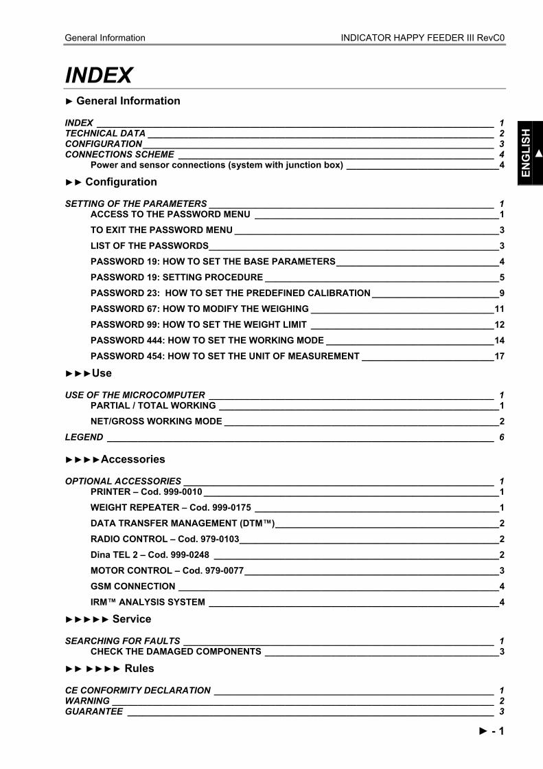
1. ON /OFF key. 2. Connectors. 3. Function and setting key. 4. 5 digit high efficiency red LED diodes 40 mm high. 5. Fixing support. 6. Identification label.

General Information INDICATOR HAPPY FEEDER III RevC0
4 - ►
CONNECTIONS SCHEME
Power and sensor connections (system with junction box)
Configuration INDICATOR HAPPY FEEDER III RevC0
ENG
LISH
►►
►► - 1
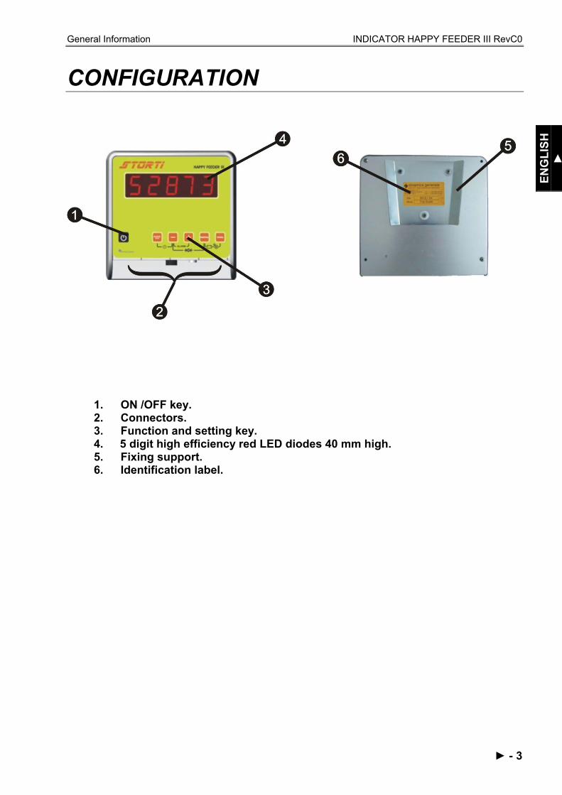
SETTING OF THE PARAMETERS
ACCESS TO THE PASSWORD MENU
1 Switch on by pressing
2 Once the last software revision has appeared on the display, upon display of…
3 Keep pressed at the same time
4 Upon display of -SET-. * Note 1
Configuration INDICATOR HAPPY FEEDER III RevC0
2 - ►►
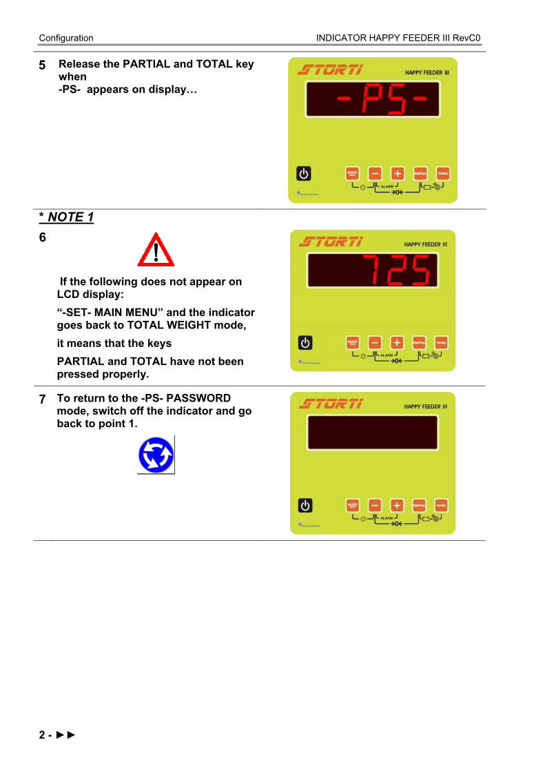
5 Release the PARTIAL and TOTAL key when -PS- appears on display…
* NOTE 1 6
If the following does not appear on LCD display: “-SET- MAIN MENU” and the indicator goes back to TOTAL WEIGHT mode, it means that the keys PARTIAL and TOTAL have not been pressed properly.
7 To return to the -PS- PASSWORD mode, switch off the indicator and go back to point 1.

Configuration INDICATOR HAPPY FEEDER III RevC0
ENG
LISH
►►
►► - 3
TO EXIT THE PASSWORD MENU
1
Set the password ZERO by using the MINUS and PLUS keys.
2 Press the ENTER key.
3 Upon display of “PLEASE WAIT” the indicator goes back to TOTAL WEIGHT mode and the weight appears on the display.
LIST OF THE PASSWORDS
19 Base parameters 23 Predefined calibration 67 Weighing modification in % (fine calibration) 99 Setting of the weight limit (over-range) 444 Setting of the unit of measurement (N/G – P/T) 454 Setting kg / Libbre

Configuration INDICATOR HAPPY FEEDER III RevC0
4 - ►►
PASSWORD 19: HOW TO SET THE BASE PARAMETERS
Password 19 includes the following base parameters:
1 From the -PS- PASSWORD mode set up the number 19, by using the MINUS and PLUS keys.
2 Confirm by pressing the ENTER key.
3 Once entered, it is necessary to roll up all the parameters by pressing the PARTIAL and TOTAL keys in order to get out.

Configuration INDICATOR HAPPY FEEDER III RevC0
ENG
LISH
►►
►► - 5
PASSWORD 19: SETTING PROCEDURE
1 ADDRESS (Default: 3) ADDRESS is an identification code which allows the indicator to get connected by RF only to those devices that communicate using the same address, with no interference with other devices using different addresses. The change of the parameter has to be done with the MINUS and PLUS keys.
To confirm and go on to the next parameter, press at the same time the PARTIAL and TOTAL keys.
2 MOTION (Default: 250) MOTION is an alarm that signals sudden weight changes that can damage the system.
If it activates, check the installation, the state of the weight system and the calibration settings. The change of the parameter has to be done with the MINUS and PLUS keys.
Dinamica Generale recommends not to change this value.
To confirm and go on to the next parameter, press at the same time the PARTIAL and TOTAL keys.

Configuration INDICATOR HAPPY FEEDER III RevC0
6 - ►►
3 RESOLUTION OF THE WEIGHT VISUALISATION (Default:2) Displayed weight resolution setting.
The setting up of the division of the Kg. to be displayed can be set at 1, 2, 5 or 10 kg always by pressing the PLUS and MINUS keys.
To confirm and go on to the next parameter, press at the same time the PARTIAL and TOTAL keys.
4
WEIGHT DEVIATION ALARM (%) (Default:10). The setting of the percentage of weight deviation to activate the sound alarm which controls the weighing, corresponds to the activation of the pre-alarm phase (intermittent acoustic signal).
This is the pre-alarm phase and the sound signal is working in an intermittent way. By setting 15, the alarm will be activated by the deviation of 15% of the programmed weight. For example, by setting 100 for the load/unload value and 15 for the percentage, the value becomes 85, activating in this way the intermittent acoustic signal. The parameter change has to be done with the MINUS and PLUS keys.
Recommended setting: 15.

Configuration INDICATOR HAPPY FEEDER III RevC0
ENG
LISH
►►
►► - 7
To confirm and go on to the next parameter, press at the same time the PARTIAL and TOTAL keys.
5 ALARM TIME (Default:7).
The programming of the sound alarm time at the end of the load/unload phase.
The set number corresponds to the duration of the sound alarm, which is expressed in seconds and starts when the programmed setting is reached.
The change of the parameter has to be done with the PLUS and MINUS keys.
The maximum programmable duration of the sound alarm is 60 seconds.
To confirm and go on to the next parameter, press at the same time the PARTIAL and TOTAL keys.
6
SETTING UP THE FILTER TO STABILIZE WHEIGHT READING (Default:4).
At low settings, the display of the weight will be very sensitive to even the slightest variation. At high settings, the weight display will be more stable and less sensitive to variation.
The change of the parameter has to be done with the MINUS and PLUS keys
Recommended setting = 4 or 5.

Configuration INDICATOR HAPPY FEEDER III RevC0
8 - ►►
7 Press at the same time the PARTIAL and TOTAL keys and the indicator will display –PS– PASSWORD-.
8 The indicator displays - P 0 -.
Configuration INDICATOR HAPPY FEEDER III RevC0
ENG
LISH
►►
►► - 9
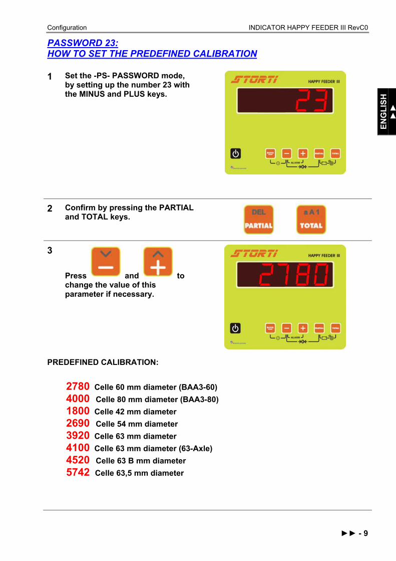
PASSWORD 23: HOW TO SET THE PREDEFINED CALIBRATION
1 Set the -PS- PASSWORD mode, by setting up the number 23 with the MINUS and PLUS keys.
2 Confirm by pressing the PARTIAL and TOTAL keys.
3
Press and to change the value of this parameter if necessary.
PREDEFINED CALIBRATION:
2780 Celle 60 mm diameter (BAA3-60) 4000 Celle 80 mm diameter (BAA3-80) 1800 Celle 42 mm diameter 2690 Celle 54 mm diameter 3920 Celle 63 mm diameter 4100 Celle 63 mm diameter (63-Axle) 4520 Celle 63 B mm diameter 5742 Celle 63,5 mm diameter

Configuration INDICATOR HAPPY FEEDER III RevC0
10 - ►►
4 Press the
keys at the same time in order to confirm the new calibration parameter, upon display of…
5 The indicator displays –P 0-.

Configuration INDICATOR HAPPY FEEDER III RevC0
ENG
LISH
►►
►► - 11
PASSWORD 67: HOW TO MODIFY THE WEIGHING
1 From the -PS- PASSWORD mode set up the number 67, by using the MINUS and PLUS keys.
2 Confirm by pressing the PARTIAL and TOTAL keys.
3 By pressing the MINUS and PLUS keys, set up the percentage of weighing modification. Selectable range: from – 10,0% to + 10,0%.
Minimum range 0,1%.
4 To confirm the parameter press the PARTIAL and TOTAL keys, until the message -END- is displayed....

Configuration INDICATOR HAPPY FEEDER III RevC0
12 - ►►
5
The indicator displays again –P 0-.
PASSWORD 99: HOW TO SET THE WEIGHT LIMIT
1
From the -PS- PASSWORD mode set up the number 99, with the MINUS and PLUS keys.
2 Confirm by pressing the PARTIAL and TOTAL keys.
3 If necessary, change the parameter by using the MINUS and PLUS keys.
This parameter depends on the capacity of the machine. Dinamica Generale recommends to put in the maximum load capacity.

Configuration INDICATOR HAPPY FEEDER III RevC0
ENG
LISH
►►
►► - 13
4 To confirm the parameter press the PARTIAL and TOTAL keys, until the message -END- is displayed…
5 The indicator displays again -PS- and -P 0-.

Configuration INDICATOR HAPPY FEEDER III RevC0
14 - ►►
PASSWORD 444: HOW TO SET THE WORKING MODE
1
From the –P 0- mode set up the number 444, by using the MINUS and PLUS keys.
2 Confirm by pressing the PARTIAL and TOTAL keys.
Setting up of the PARTIAL/TOTAL or GROSS/NET working mode by pressing the keys MINUS and PLUS.
3
Setting up the “1 P-t” PARTIAL/TOTAL mode, press the TOTAL key to display the total weight loaded in that moment. In order to do partial weighing, press the PARTIAL key: the display is zeroed and it will increase its value at the increasing of the loaded weight.
Once all the partial weighing has been done, press TOTAL to display the total weight loaded till that moment. Passing from PARTIAL to TOTAL mode, the previously displayed partial weight gets lost, for each partial weighing is added up to the total one.
Configuration INDICATOR HAPPY FEEDER III RevC0
ENG
LISH
►►
►► - 15
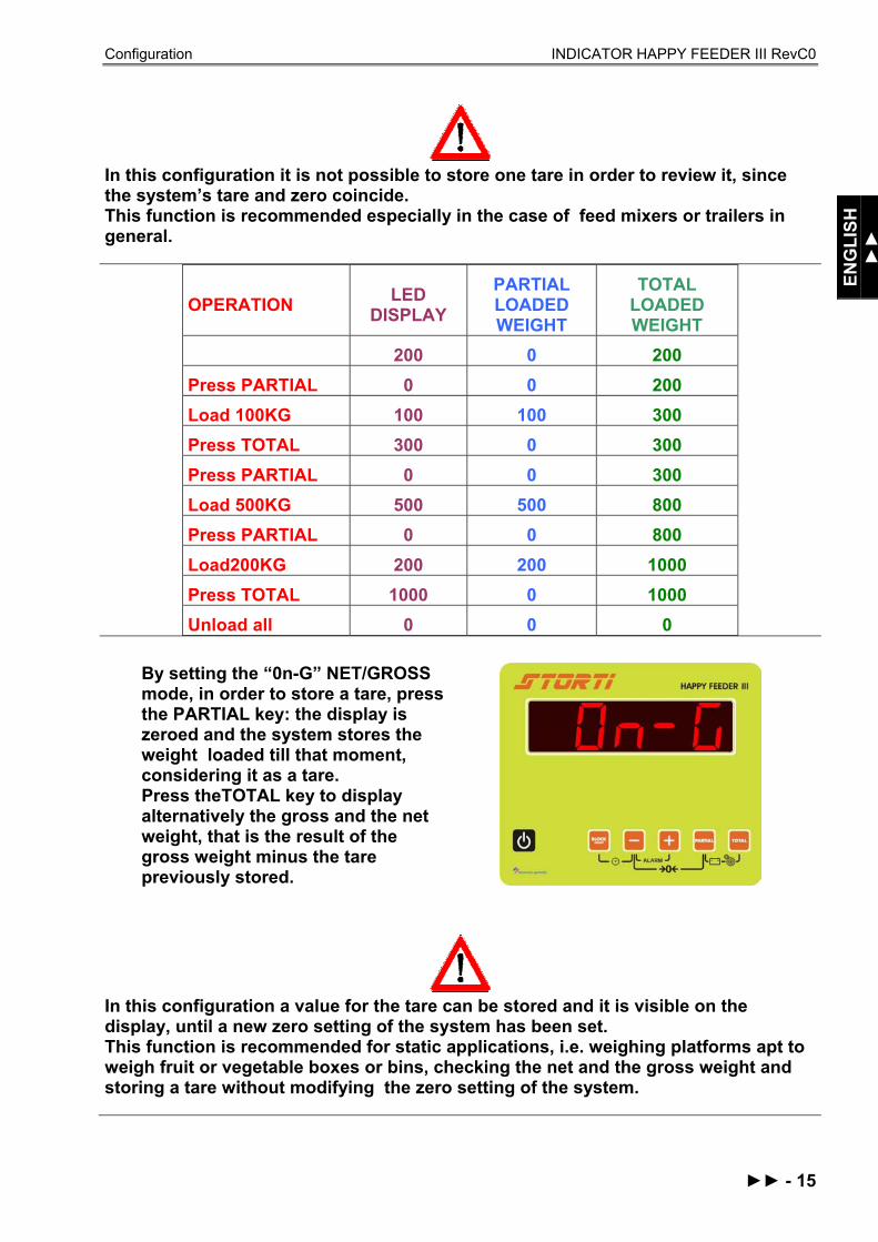
In this configuration it is not possible to store one tare in order to review it, since the system’s tare and zero coincide. This function is recommended especially in the case of feed mixers or trailers in general.
OPERATION LED DISPLAY
PARTIAL LOADED WEIGHT
TOTAL LOADED WEIGHT
200 0 200 Press PARTIAL 0 0 200 Load 100KG 100 100 300 Press TOTAL 300 0 300 Press PARTIAL 0 0 300 Load 500KG 500 500 800 Press PARTIAL 0 0 800 Load200KG 200 200 1000 Press TOTAL 1000 0 1000 Unload all 0 0 0
By setting the “0n-G” NET/GROSS mode, in order to store a tare, press the PARTIAL key: the display is zeroed and the system stores the weight loaded till that moment, considering it as a tare. Press theTOTAL key to display alternatively the gross and the net weight, that is the result of the gross weight minus the tare previously stored.
In this configuration a value for the tare can be stored and it is visible on the display, until a new zero setting of the system has been set. This function is recommended for static applications, i.e. weighing platforms apt to weigh fruit or vegetable boxes or bins, checking the net and the gross weight and storing a tare without modifying the zero setting of the system.

Configuration INDICATOR HAPPY FEEDER III RevC0
16 - ►►
OPERATION LED DISPLAY NET WEIGHT GROSS
WEIGHT TARE
200 0 200 200
Press PARTIAL 0 0 200 200
100 0 200 200
Press TOTAL 200 0 200 200
Load 100KG 300 100 300 200
Press TOTAL 100 100 300 200
Load 500KG 600 600 800 200
Press TOTAL 800 600 800 200
Unload all 200 0 200 200
Press TOTAL 0 0 200 200
4 To confirm the parameter, press the PARTIAL and TOTAL keys. The message displayed is again -P 0-.

Configuration INDICATOR HAPPY FEEDER III RevC0
ENG
LISH
►►
►► - 17
PASSWORD 454: HOW TO SET THE UNIT OF MEASUREMENT
By setting up U or M: Pounds the weight is displayed in Pounds (lb).
One pound = 0,454 kg
By setting up U o M: Kg the weight is displayed in kilograms (kg).
1
From the -PS- PASSWORD mode set up the number 454, by pressing the MINUS and PLUS keys.
2 Confirm by pressing the PARTIAL and TOTAL keys.
3 Set up the unit of measurement in kilograms (kg) or in pounds (lb) by pressing the MINUS and PLUS keys. The same choice will be indicated beside the weight value on all the printed coupons.

Configuration INDICATOR HAPPY FEEDER III RevC0
18 - ►►
4
To confirm the parameter, press the PARTIAL and TOTAL keys. The message -PS- PASSWORD appears on the display.

Use INDICATOR HAPPY FEEDER III RevC0
ENG
LISH
►►►
►►► - 1
USE OF THE MICROCOMPUTER
SWITCH ON a) Switch on the equipment by pressing
, the last software revision appears on the display, then the message “PLEASE WAIT”.
b) A weight value appears on the red
LED display.
It is recommended to use the indicator at least 15 minutes after the switching, especially in case of cold temperatures (<0°C).
* The weight value is just symbolical
PARTIAL / TOTAL WORKING
ZEROING a) By using the MINUS and PARTIAL
keys, zero the system. b) The message
-TA- appears; keep pressed the MINUS and PARTIAL keys, until the message -END- is displayed.
c) The message of the indicator is again TOTAL WEIGHT.
* The weight value is just symbolical

Use INDICATOR HAPPY FEEDER III RevC0
2 - ►►►
The zeroing of the system is a very delicate passage. It depends also on the machine’s conditions, on the soil’s and temperature’s conditions, and on the mechanical stresses. In fact, if the machine is moving on a sloping surface or it is subjected to a different range of temperature or to different mechanical conditions, it is likely that the value displayed may change during the weighing process. A displayed weight value of 0 Kg for a machine on a plane surface, could change for a machine moving on a sloping surface.
PARTIAL WEIGHING a) After zeroing the displayed weight by
pressing the PARTIAL key (while the previously displayed value has been stored), it is possible to load/unload other material, starting from a fixed value.
b) Once the load/unload phase has been
executed, another partial weighing can be displayed, repeating all the passages starting from the “a” or even displaying the total weight by pressing the TOTAL key. The total weight is the sum of all the partial weighings.
* The weight value is just symbolical
NET/GROSS WORKING MODE ZEROING a) Zero the system by pressing the
MINUS and PARTIAL keys b) The messages
-TA-, -END- and –TOT- appears.
c) The indicator displays again GROSS
WEIGHT. After zeroing the system, net and gross weight coincide and correspond to zero.
* The weight value is just symbolical

Use INDICATOR HAPPY FEEDER III RevC0
ENG
LISH
►►►
►►► - 3
NET/GROSS WEIGHT a) In this mode the PARTIAL key is used
to store a tare.
Now the weight “zero” is displayed and the previously displayed one is summed up to the gross weight. By pressing the TOTAL key, the NET WEIGHT and the GROSS WEIGHT are alternatively displayed. The net weight is the gross weight minus the previously stored tare.
LOAD WITH ALARM Available in both the working modes.
a) Starting from the TOTAL WEIGHT or
GROSS WEIGHT mode, press at the same time the MINUS and PLUS keys, until the message –AL- is displayed.
b) Set up the weight with the MINUS and
PLUS keys.

Use INDICATOR HAPPY FEEDER III RevC0
4 - ►►►
c) Confirm the set weight by pressing
the PARTIAL key and go on with the load/upload phase. The weight is displayed with a decreasing order, despite the fact it is laoding/unloading.
Once the percentage that has been set up with Password 19 (see -PAL-PREALARM) has been reached, the alarm signal starts sounding in an intermittent way. When the programmed duration of the sound alarm, that has been set up with the password 19, is over, the acoustic signal becomes continuous (see -AT- ALARM TIME). d) At the end the indicator passes
automatically on TOTAL WEIGHT or GROSS WEIGHT.
UNLOAD WITH ALARM Follow the same procedure of the LOAD WITH ALARM. The instrument automatically recognises the unloading phase.
If a load/unload alarm has already been set and during the transfer of the instrument the weight changes, then it is possible to reset it by pressing the PARTIAL key. If the indicator is switched off with a set load/unload alarm, this value is set at zero.
* The alarm value is just symbolical.

Use INDICATOR HAPPY FEEDER III RevC0
ENG
LISH
►►►
►►► - 5
ADDICTIONAL FUNCTIONS BATTERY CONTROL
Hold pressed the keys at the same time in TOTAL WEIGHT or GROSS WEIGHT mode, in order to display the voltage of the battery.
THE NEXT FUNCTIONS ARE AVAILABLE ONLY IF THE INSTRUMENT IS EQUIPPED TO BE CONNECTED TO THE PRINTER (FULL VERSION). This note is suitable only for the non-HP indicators.
a) In order to print the weight value, hold pressed the PRINT BLOCK key for 3 seconds, as confirmed by the message on the display. Then the indicator returns to TOTAL WEIGHT.
Always check that the printer is properly connected to the indicator before proceeding on with the printing.
WEIGHT BLOCK It is possible to block the weight on the display in any given moment. By pushing the PRINT BLOCK key the weight will be memorized and blocked; the message BLO- will appear on the indicator. In order to return to the manual mode push again the PRINT BLOCK key. Once this operation has been carried out the weight before the block function was activated will be seen on the indicator. If the weight block mode was activated without error it is possible to exit the block function without memorizing the weight by pushing the TOTAL key.

Use INDICATOR HAPPY FEEDER III RevC0
6 - ►►►
LEGEND CONVENTIONAL SIGNS This handbook uses some conventional signs, in order to lead the user during the reading of important instructions and advices; these regard especially the setting of the parameters of the system and thus its correct working. Please pay attention to the following icons:
It indicates explaining and further information.
It highly recommends to pay attention.
It signals an operation that can be repeated many times, cyclically.
It highlights a double working option.
It suggests to follow some hint.
*
It signals that the weight value on the red LED display is just symbolical, because put in as an instance. It can also signal the presence of notes.

Accessories INDICATOR HAPPY FEEDER III RevC0
ENG
LISH
►►►►
►►►► - 1
OPTIONAL ACCESSORIES
• It is connectable to every Dinamica generale microcomputer. • Possibility to define the customer’s headline, name, address, company title etc... • Watertight case IP65 for critical environment. • Low cost of maintenance. • Operating temperature from 0 to 50°C. • Thermal Roll paper, width 57,5 mm, max. diameter 50 mm. • Print module with thermal impact. • In accordance with EEC directives. • During manual working, it is possible to print the current weight value (TOTAL and/or PARTIAL) with
date and time by pressing the PRINT key. • During the execution of loading or unloading with program, the RECIPE or the UNLOADING program
are automatically printed at the end of the process. • As for the printing of LOADING and UNLOADING programmes stored in the weight system see the
specific instructions in the user’s manual of the microcomputer in use • In order to get the advancing of the paper by hand, press the Feed key on the printer panel.
Weight repeater display with big digits connectable to every microcomputer • Dimensions 281 x 125 x 90. • High efficiency red “led diodes” display 60 mm high. • Display visibility over 20 meters. • Weight reading up to 99.999 Kg / Pounds. • ABS with IP66 protection, noise shielded. • Simple connection direct to microcomputers DINAMICA GENERALE. • Possibility of a series connection of more displays. • Every datum which is displayed by the microcomputer is repeated on the Weight Repeater • Possibility to convert a wire communication to a wireless (WINET™) one at any time.
PRINTER – Cod. 999-0010
Happy Feeder III
Happy Feeder Plus III
Top Feeder
О √ √
WEIGHT REPEATER – Cod. 999-0175
Happy Feeder III
Happy Feeder Plus III
Top Feeder
O √ √

Accessories INDICATOR HAPPY FEEDER III RevC0
2 - ►►►►
Data transfer on the Cartridge, from the microcomputer to the PC and vice-versa • With Data Transfer installed on your weight system, you can store all work phases and then check and
analyse them. • 6 months continuous acquisition. • Programming for 99 Recipes each with 24 components. • Storage and costs control and statistics analysis.
Radio Frequency communication (WiNET™) • Repeat all the functions of the microcomputer (except ON / OFF). • Range up to 25 meters. • Battery type AAA 1,5 Volt. • Autonomy 120 days (normal function).
Radio Frequency communication (WiNET™) • Hand held control for remote control of the weight system up to 25 metres from the microcomputer, with
possibility to execute the main functions: Tare of the system;
Total and partial weighing;
Execution of loadings;
Visualisation of weight and of functions on graphical display.
DATA TRANSFER MANAGEMENT (DTM™)
Happy Feeder III
Happy Feeder Plus III
Top Feeder
О - √
RADIO CONTROL – Cod. 979-0103
Happy Feeder III
Happy Feeder Plus III
Top Feeder
O √ -
Dina TEL 2 – Cod. 999-0248
Happy Feeder III
Happy Feeder Plus III
Top Feeder
O √ √
Accessories INDICATOR HAPPY FEEDER III RevC0
ENG
LISH
►►►►
►►►► - 3
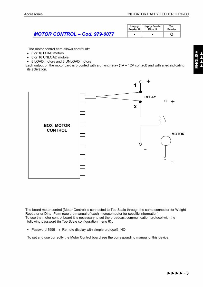
MOTOR CONTROL – Cod. 979-0077
Happy Feeder III
Happy Feeder Plus III
Top Feeder
- - О
The motor control card allows control of:: • 8 or 16 LOAD motors • 8 or 16 UNLOAD motors • 8 LOAD motors and 8 UNLOAD motors
Each output on the motor card is provided with a driving relay (1A – 12V contact) and with a led indicating its activation.
The board motor control (Motor Control) is connected to Top Scale through the same connector for Weight Repeater or Dina- Palm (see the manual of each microcomputer for specific information). To use the motor control board it is necessary to set the broadcast communication protocol with the following password (in Top Scale configuration menu 6) : • Password 1999 → Remote display with simple protocol? NO To set and use correctly the Motor Control board see the corresponding manual of this device.
+
-
MOTOR
1
2
-
+
BOX MOTOR CONTROL
RELAY

Accessories INDICATOR HAPPY FEEDER III RevC0
4 - ►►►►
The GSM communication module allows Dina Service remote service center to: • Check the status of Top Scale installed in customers’ farm • Work on configuration parameters of Top Scale in case the customer needs it
The GSM communication module is connected to specific connector through GSM and Can Bus (see the manual of each microcomputer for specific information).
Besides the execution of the normal weighing operations with/without loading/unloading programs, the Top Scale microcomputer can also have a accessory system I.R.M. (Intelligent Ration Management). The purpose of the IRM ™ system is: • To analyse the alimentary components that have to be loaded according to the loading recipes • To Modulate the weight of the components set in the recipes, according to the values of chemical
parameters requested by the nutritionist that the breeder is following In particular there are two types of IRM™ systems: • "Advanced" IRM™ that enables analysing of the components as regards only the parameter
HUMIDITY • “Professional IRM ™" that enables analysing of the components as regards the chemical parameters
HUMIDITY, STARCH, PROTEIN, FIBER ADF, FIBER NDF, ASHES In order to set up the IRM™ system on the Top Scale microcomputer you need to enter the password: Password 113 → IRM™ setting parameters.
For further information about the setting and the correct use of the IRM™ system please see the appropriate manual supplied with this accessory device.
Legend:
GSM CONNECTION
Happy Feeder III
Happy Feeder Plus III
Top Feeder
- - О
IRM™ ANALYSIS SYSTEM
Happy Feeder III
Happy Feeder Plus III
Top Feeder
- - О
√ Standard accessory interface О Accessory interface on request - Accessory interface not available
Service INDICATOR HAPPY FEEDER III RevC0
ENG
LISH
►►►►►
►►►►► - 1
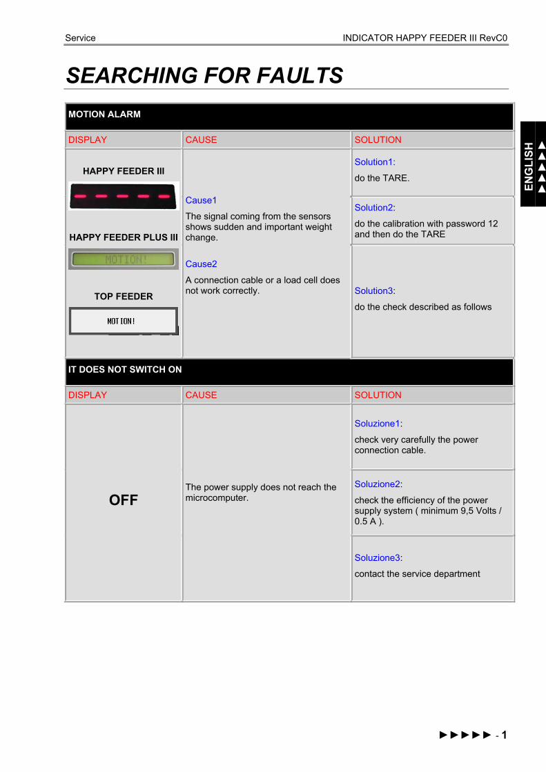
SEARCHING FOR FAULTS
MOTION ALARM
DISPLAY CAUSE SOLUTION
HAPPY FEEDER III
HAPPY FEEDER PLUS III
TOP FEEDER
Cause1
The signal coming from the sensors shows sudden and important weight change.
Cause2
A connection cable or a load cell does not work correctly.
Solution1:
do the TARE.
Solution2:
do the calibration with password 12 and then do the TARE
Solution3:
do the check described as follows
IT DOES NOT SWITCH ON
DISPLAY CAUSE SOLUTION
OFF The power supply does not reach the microcomputer.
Soluzione1:
check very carefully the power connection cable.
Soluzione2:
check the efficiency of the power supply system ( minimum 9,5 Volts / 0.5 A ).
Soluzione3:
contact the service department
Service INDICATOR HAPPY FEEDER III RevC0
2 - ►►►►►
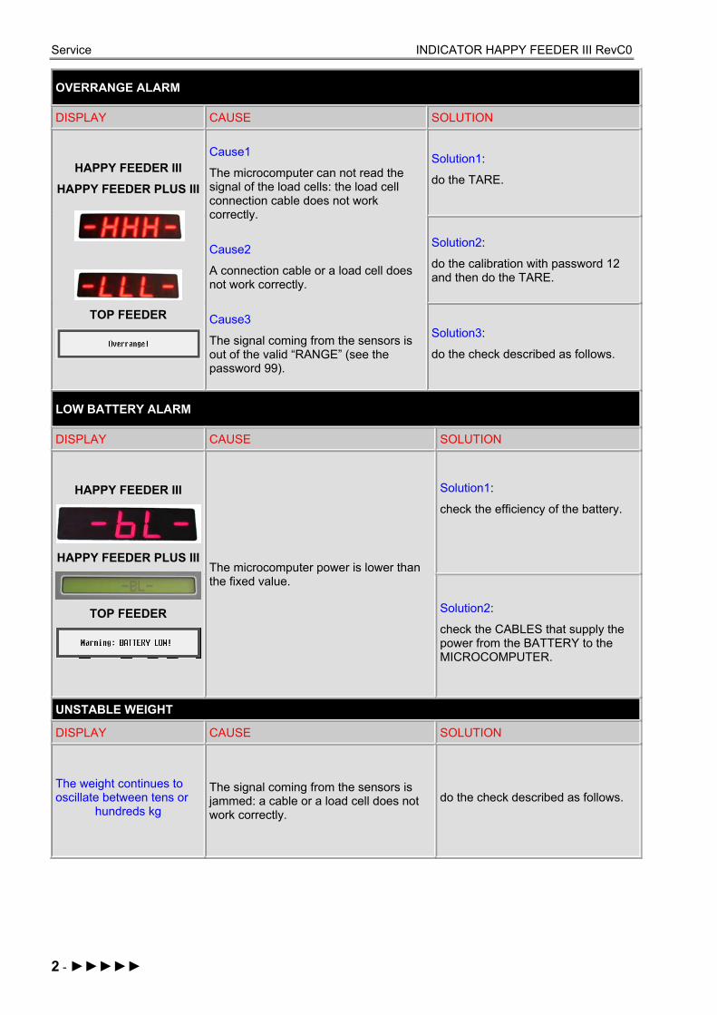
OVERRANGE ALARM
DISPLAY CAUSE SOLUTION
HAPPY FEEDER III
HAPPY FEEDER PLUS III
TOP FEEDER
Cause1
The microcomputer can not read the signal of the load cells: the load cell connection cable does not work correctly.
Cause2
A connection cable or a load cell does not work correctly.
Cause3
The signal coming from the sensors is out of the valid “RANGE” (see the password 99).
Solution1:
do the TARE.
Solution2:
do the calibration with password 12 and then do the TARE.
Solution3:
do the check described as follows.
LOW BATTERY ALARM
DISPLAY CAUSE SOLUTION
HAPPY FEEDER III
HAPPY FEEDER PLUS III
TOP FEEDER
The microcomputer power is lower than the fixed value.
Solution1:
check the efficiency of the battery.
Solution2:
check the CABLES that supply the power from the BATTERY to the MICROCOMPUTER.
UNSTABLE WEIGHT
DISPLAY CAUSE SOLUTION
The weight continues to oscillate between tens or
hundreds kg
The signal coming from the sensors is jammed: a cable or a load cell does not work correctly.
do the check described as follows.

Service INDICATOR HAPPY FEEDER III RevC0
ENG
LISH
►►►►►
►►►►► - 3
CHECK THE DAMAGED COMPONENTS
DEFINE THE TEST PROCEDURE:
HAVE YOU GOT A WEIGHING
SIMULATOR DG 979-0007?
EXECUTE PROCEDURE 4
EXECUTE PROCEDURE 3
HAVE YOU GOT A SYSTEM WITH
JUNCTION BOX?
EXECUTE PROCEDURE 2
EXECUTE PROCEDURE 1
HAVE YOU GOT A SYSTEM WITH
JUNCTION BOX?
YES
NO
NO YES
YES
NO

Service INDICATOR HAPPY FEEDER III RevC0
4 - ►►►►►
PROCEDURE 1 Ref. YES / YES
Check the working of the scale
a) Switch off the microcomputer.
b) Disconnect the sensor cable between the scale and the junction box.
c) Connect the WEIGHT SIMULATOR (calibrator 979-0007) with the lever in position “Var” (varying) to the SENSRORS connector of the scale.
d) Switch on the microcomputer.
e) Do the TARE (for the execution see the microcomputer manual).
f) The scale has to become stable displaying “0” kg.
g) Verify the correct functioning of the scale by turning the WEIGHT SIMULATOR knob (turning clockwise increases the weight, counter-clockwise decreases the weight).
RESULT CAUSE ACTION Zero stable and
correct functioning The microcomputer is NOT
damaged Proceed with the other tests
Zero NOT stable or NOT correct functoning
The microcomputer is damaged Contact the service department
Check the functioning of the SENSOR CABLES and of the JUNCTION BOX
a) Switch off the microcomputer.
b) Open the JUNCTION BOX.
c) Disconnect the sensors, leaving only the cable that reaches the weight system (SENSOR CABLES).
d) Connect the WEIGHT SIMULATOR (979-0007) in place of one of the sensors using the proper adaptor. .
e) Switch on the microcomputer.
f) Do the TARE (use the microcomputer’s manuals for instructions).
g) The scale has to become stable displaying “0” kg.
h) Check the correct functioning by turning the knob of the WEIGHT SIMULATOR (turning clockwise, the weight increases, counter clockwise, the weight decreases).
REPEAT THE TEST CONNECTING THE WEIGHT SIMULATOR IN PLACE OF EACH SENSOR.
Service INDICATOR HAPPY FEEDER III RevC0
ENG
LISH
►►►►►
►►►►► - 5
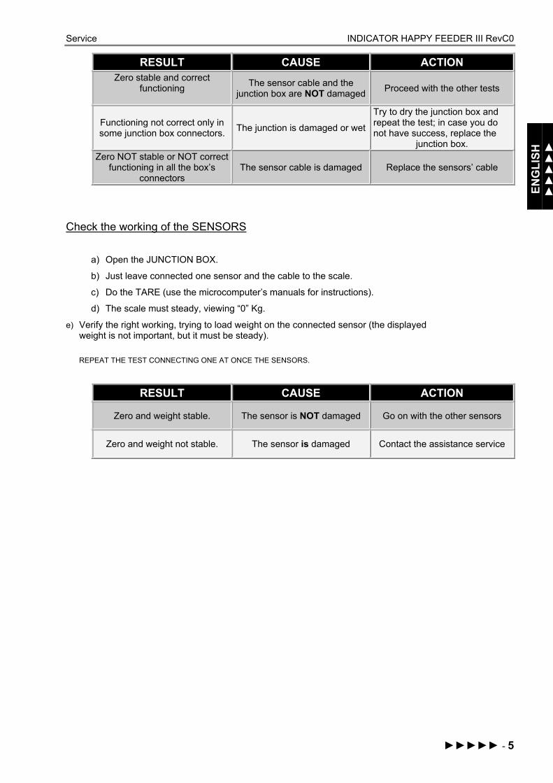
RESULT CAUSE ACTION Zero stable and correct
functioning
The sensor cable and the junction box are NOT damaged Proceed with the other tests
Functioning not correct only in some junction box connectors. The junction is damaged or wet
Try to dry the junction box and repeat the test; in case you do not have success, replace the
junction box. Zero NOT stable or NOT correct
functioning in all the box’s connectors
The sensor cable is damaged Replace the sensors’ cable
Check the working of the SENSORS
a) Open the JUNCTION BOX.
b) Just leave connected one sensor and the cable to the scale.
c) Do the TARE (use the microcomputer’s manuals for instructions).
d) The scale must steady, viewing “0” Kg.
e) Verify the right working, trying to load weight on the connected sensor (the displayed weight is not important, but it must be steady). REPEAT THE TEST CONNECTING ONE AT ONCE THE SENSORS.
RESULT CAUSE ACTION
Zero and weight stable. The sensor is NOT damaged Go on with the other sensors
Zero and weight not stable. The sensor is damaged Contact the assistance service

Service INDICATOR HAPPY FEEDER III RevC0
6 - ►►►►►
PROCEDURE 2 Ref. YES / NO
Check the functioning of the scale
a) Switch off the microcomputer.
b) Disconnect all the sensors.
c) Connect the WEIGHT SIMULATOR (calibrator) with the lever in " “Var” (varying) position to one of the sensor connectors of the weighing system.
d) Switch on the microcomputer.
e) Do the TARE (use the microcomputer’s manuals for instructions).
f) The scale must steady, viewing “0” Kg.
g) Verify the correct functioning, turning the knob of the WEIGHT SIMULATOR (clockwise, the weight increase, anticlockwise, the weight decreases
REPEAT THE TEST CONNECTING THE WEIGHT SIMULATOR AT THE PLACE OF EACH SENSOR.
RESULT CAUSE ACTION
Zero stable and correct working of all the connectors The sensor is NOT damaged Go on with the other tests.
Zero not stable and incorrect working of all the connectors The sensor is damaged Contact the assistance service
Check the working of the SENSORS
a) Switch-off the microcomputer.
b) Just leave one sensor connected to the scale connector.
c) Switch-on the microcomputer.
d) Do the TARE (use the microcomputer’s manuals for instructions).
e) The scale has to be stable, displaying “0” Kg.
f) Check the correct functioning, by trying to load weight on the connected sensor (the displayed weight is not important, but it must be steady).
REPEAT THE TEST CONNECTING THE SENSORS ONE AT A TIME.
RESULT CAUSE ACTION
Zero and weight stable. The sensor is NOT damaged Proceed with the other sensors.
Zero and weight not stable. The sensor is damaged Proceed with the other sensors. Contact the assistance service.

Service INDICATOR HAPPY FEEDER III RevC0
ENG
LISH
►►►►►
►►►►► - 7
PROCEDURE 3 Ref. NO / YES
Check the functioning of the SYSTEM and of the SENSORS
a) Switch off the microcomputer.
b) Open the JUNCTION BOX.
c) Just leave connected one sensor and the cable to the scale (SENSORS’ CABLE).
d) Switch on the microcomputer.
e) Do the TARE (use the microcomputer manuals for instructions).
f) The scale has to be stable, displaying “0” Kg.
g) Verify the correct functioning, trying to load weight on the connected sensor (the displayed weight is not impostnat, but it must be steady).
REPEAT THE TEST CONNECTING ONE AT ONCE EACH SENSOR IN ITS FIRST POSITION
RESULT CAUSE ACTION
Zero and weight stable in all the connectors The system works correctly. Connect everything and try again
with normal use.
Zero and weight NOT stable only in some connectors of the
junction box
The box and the sensors connected to those connectors
are damaged
Connect a working sensor to the “critical” connector; repeat the test and check the two following
lines. With a new sensor: zero and
weight NOT stable. The junction box is damaged. Replace the junction box and repeat the tests.
With a new sensor: zero and weight stable.
The sensor previously connected is damaged. Contact the assistance service
Zero and weight NOT stable in all the connectors of the
junction box
The sensor cable or the microcomputer is damaged
Replace the sensor cable, repeatthe tests and check the following
line. Zero and weight NOT stable
yet The microcomputer is
damaged Contact the assistance service

Service INDICATOR HAPPY FEEDER III RevC0
8 - ►►►►►
PROCEDURE 4 Ref. NO / NO
Check the functionig of the SYSTEM and of the SENSORS
a) Switch off the microcomputer.
b) Just leave connected one sensor to the scale.
c) Switch on the microcomputer.
d) Do the TARE (use the microcomputer’s manuals for instructions).
e) The scale has to be stable, displaying “0” Kg.
f) Check the correct functioningtrying to load weight on the connected sensor (the displayed weight is not important, but it must be steady).
REPEAT THE TEST CONNECTING EACH SENSOR, ONE AT A TIME, IN THE ORIGINAL CONNECTOR .
RESULT CAUSE ACTION Zero and weight of a sensor
NON stable. The sensor is damaged Contact the assistance service
Zero and weight of all the sensors on the same connector
NOT stable
The microcomputer is damaged Contact the assistance service
Zero and weight stable with all the sensors in the same
connector None Repeat the test with another
scale connector.
Zero and weight stable with all the sensors in all the
connectors The system works correctly. Connect everything and try again
in normal use

Rules INDICATOR HAPPY FEEDER III RevC0
ENG
LISH
►►►►►►
►►►►►► - 1
CE CONFORMITY DECLARATION Company: Dinamica Generale srl Address: Via Mondadori, 15 46025 Poggio Rusco (MN) ITALY WE DECLARE THAT THE PRODUCT:
Model: All weighing microcomputer Dinamica Generale
Description: Simple and programmable weighing system
Options: All the configurations is in conformity with all the essential requirements of European Directive 2004/108/EC, making with the following directives: EMC for emission:
EN 61326-1 EN 55011(1999) – A1(2000) – A2(2003)
EMC for immunity: EN 61000-4-2 (96) – A1 (99) – A2 (01) EN 61000-4-3 (97) – A1 (02) EN 61000-4-4 (96) – A1 (01) – A2 (01) EN 61000-4-5 – (1997) EN 61000-4-6 (97) – A1 (01) EN 61000-4-8 (97) – A1 (01) The systems were tested in a typical configuration with "Dinamica Generale s.r.l." load cells. POGGIO RUSCO, 28/08/2006
Rules INDICATOR HAPPY FEEDER III RevC0
2 - ►►►►►►
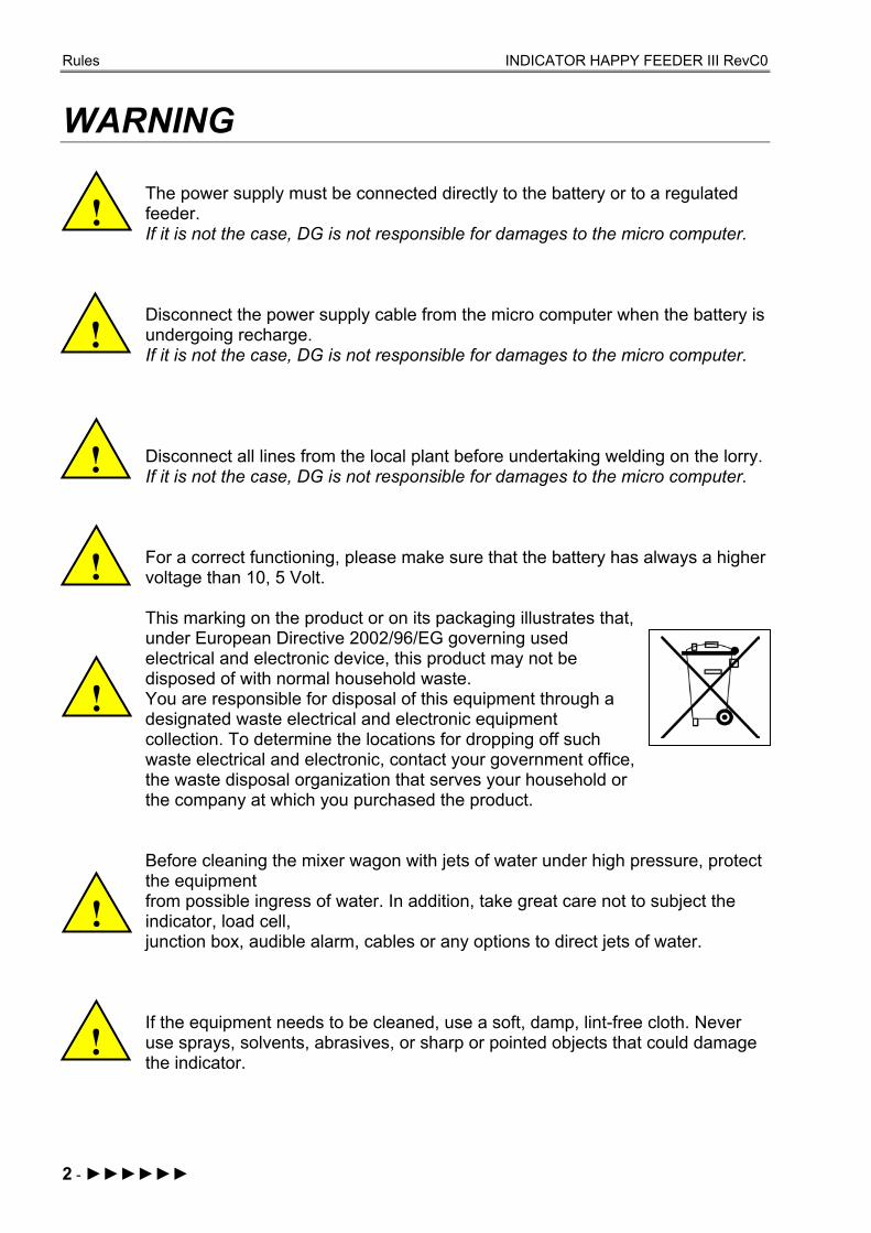
WARNING
The power supply must be connected directly to the battery or to a regulated feeder. If it is not the case, DG is not responsible for damages to the micro computer. Disconnect the power supply cable from the micro computer when the battery is undergoing recharge. If it is not the case, DG is not responsible for damages to the micro computer. Disconnect all lines from the local plant before undertaking welding on the lorry. If it is not the case, DG is not responsible for damages to the micro computer. For a correct functioning, please make sure that the battery has always a higher voltage than 10, 5 Volt. This marking on the product or on its packaging illustrates that, under European Directive 2002/96/EG governing used electrical and electronic device, this product may not be disposed of with normal household waste. You are responsible for disposal of this equipment through a designated waste electrical and electronic equipment collection. To determine the locations for dropping off such waste electrical and electronic, contact your government office, the waste disposal organization that serves your household or the company at which you purchased the product. Before cleaning the mixer wagon with jets of water under high pressure, protect the equipment from possible ingress of water. In addition, take great care not to subject the indicator, load cell, junction box, audible alarm, cables or any options to direct jets of water. If the equipment needs to be cleaned, use a soft, damp, lint-free cloth. Never use sprays, solvents, abrasives, or sharp or pointed objects that could damage the indicator.
!
!
!
!
!
!
!

Rules INDICATOR HAPPY FEEDER III RevC0
ENG
LISH
►►►►►►
►►►►►► - 3
GUARANTEE The supplier guarantees, for 24 months from the delivery date, the good quality of materials used, the excellent construction and the steady functioning of the instrument they have manufactured and that bears the trademark or the production serial number. During the guarantee period the supplier undertakes to repair or replace, free supplier’s head office, faulty parts due to poor materials or faulty construction, provided that such parts are delivered free port supplier’s head office. Shortcomings and defects due to incorrect use of instruments, inadequate maintenance, changes carried out without the supplier’s approval, normal wear are not included in this guarantee. Liability and compensations by the supplier due to direct or indirect damages to persons, objects or production, even as a consequence of faulty functioning of the supplied instruments or of material or construction defects, are not included in this guarantee. Dinamica Generale maintains the faculty to modify the content of this handbook due to hardware and software implementations in order to improve their products and thus to guarantee the best service to their users.
NOTES:

Rules INDICATOR HAPPY FEEDER III RevC0
4 - ►►►►►►
Congratulations Dear User! You have chosen a product by Dinamica Generale, a leader company in the development and production of electronic weighing systems, automation and NIR solutions, and with high technological level in every field of application: zootechnical, feeding, industrial and biomedical. Year by year the international market recognizes our quality, our experience, our reliability and most of all our innovative technology, as a mark of an highly developed and innovative know how. These are the pillars of our job and according with these beliefs we are at your service, providing you with a simple as well as new, precise and professional product, which is going to make your job easier for many years. This handbook aims to take you through the different performances of the weighing system in the most comfortable way and to show you some new functions as well. Dinamica Generale does not forget to provide you even with the basic information: the configuration, the use of different accessories at your disposal, the service of “searching for faults” and the equipment’s safety rules, in order to guarantee to our customers always more and more support and technical assistance and help for the years to come. Now there is nothing left for us to do but wish you all the best!
The team of Dinamica Generale

������������ ������