Embed Size (px)
Citation preview

High-sensitivity optical sensor高感度光センサー

116 CITIZEN ELECTRONICS CO., LTD. JAPAN 2010.12
あらゆる情報検出から赤外線データ通信まで、幅広い
用途に使える、超小型&高感度・光センサー。
Ultra-compact, high-sensitivity optical sensors for various app lications
ranging from information detection to infrared data communicati on
CITISENSOR(当社商標)は、非可視光線である赤外光の受・発
光素子(赤外LED、フォトトランジスタ、フォトダイオード)を
高感度センサーとして活用した製品です。各種情報検出、情報伝達
機器に利用され、とりわけ最近ではパソコンとプリンター間、ある
いはPDA とパソコン間など、赤外線通信の分野へも活躍の場を
広げています。いずれも超小型・高感度を実現するとともに、表面
実装技術に対応しています。
The CITISENSOR (Citizen trademark) series makes
use of infrared light emitting and receiving devices
(infrared LEDs, phototransistors, photodiodes).
The highly sensitive sensors are proving useful in
many applications. A growing trend is their use
for infrared links, for example between computer
and printer, or PDA and computer. All CITISENSOR
products feature compact dimensions, high
sensitivity, and are suitable for surface mounting.
1.全機種SMD(表面実装)タイプのセンサーです。
2.全てのCITISENSORはリフローはんだが可能です。
1. SMD (Surface Mount Device) type sensors are used
for all models.2. Reflow-soldering is available for all CITISENSORs.
高出力
High output
CITISENSOR
超小型
Ultra small sizeCL-170IR-X
CL-190IR-X
CPT Series
CPI Series
PR Series
CIM Series
CL-330IRS-X
赤外チップLED
Infrared chip LED
チップフォトトランジスタ
Chip photo-transistor
フォトインタラプタ
Photo-interrupter
フォトリフレクタ
Photo-reflector
赤外線データ通信モジュール
IrDA compliant transceiver
赤外線リモートコントロール受光ユニット
Infrared remote control receiver unitRS Series
特徴 Features
製品構成 Composition of Products

117CITIZEN ELECTRONICS CO., LTD. JAPAN 2010.12
携帯電話 Cellular phone
リモコン Remote control
送信用赤外線光源 Infrared transmitter
DVDビデオレコーダー DVD video recorder
ディスク位置検出センサー Optical detection sensor
コンピュータ Computer
赤外線通信(IrDA)モジュール Infrared data association module
ディスク位置検出センサー Optical detection sensor
デジタルカメラ Digital still camera
PDA Personal digital assistant
タッチパネルセンサー Touch panel sensor
送信用赤外線光源 Infrared transmitter
赤外線通信(IrDA)モジュール Infrared data association module
エアコン Air conditioner
リモコン受光部 Infrared signal receiver for remote control
マウス Mouse
ボール回転検出センサー Mouse ball detection sensor
外光検知用受光センサー Sensor for detecting infrared signals
赤外線通信(IrDA)モジュール Infrared data association module
送信用赤外線光源 Infrared transmitter
ズーム位置検出センサー Focus position detection sensor
用途 Applications
118
CITIZEN ELECTRONICS CO., LTD. JAPAN 2010.12
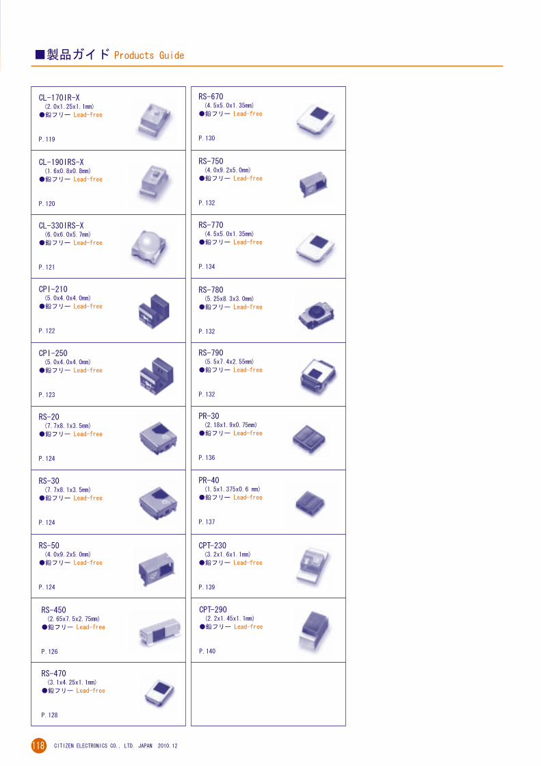
製品ガイド Products Guide
CL-330IRS-X(6.0x6.0x5.7mm)
鉛フリー Lead-free
P.121
CL-170IR-X(2.0x1.25x1.1mm)
鉛フリー Lead-free
P.119
CL-190IRS-X(1.6x0.8x0.8mm)
鉛フリー Lead-free
P.120
CPT-230(3.2x1.6x1.1mm)
鉛フリー Lead-free
P.139
CPT-290(2.2x1.45x1.1mm)
鉛フリー Lead-free
P.140
PR-30(2.18x1.9x0.75mm)
鉛フリー Lead-free
P.136
CPI-210(5.0x4.0x4.0mm)
鉛フリー Lead-free
P.122
RS-50(4.0x9.2x5.0mm)
鉛フリー Lead-free
P.124
RS-30(7.7x8.1x3.5mm)
鉛フリー Lead-free
P.124
RS-20(7.7x8.1x3.5mm)
鉛フリー Lead-free
P.124
RS-670(4.5x5.0x1.35mm)
鉛フリー Lead-free
P.130
RS-770(4.5x5.0x1.35mm)
鉛フリー Lead-free
P.134
RS-790(5.5x7.4x2.55mm)
鉛フリー Lead-free
P.132
RS-780(5.25x8.3x3.0mm)
鉛フリー Lead-free
P.132
RS-750(4.0x9.2x5.0mm)
鉛フリー Lead-free
P.132
RS-470(3.1x4.25x1.1mm)
鉛フリー Lead-free
P.128
RS-450(2.65x7.5x2.75mm)
鉛フリー Lead-free
P.126
CPI-250(5.0x4.0x4.0mm)
鉛フリー Lead-free
P.123
PR-40(1.5x1.375x0.6 mm)
鉛フリー Lead-free
P.137
119
CITIZEN ELECTRONICS CO., LTD. JAPAN 2010.12
赤外チップLED
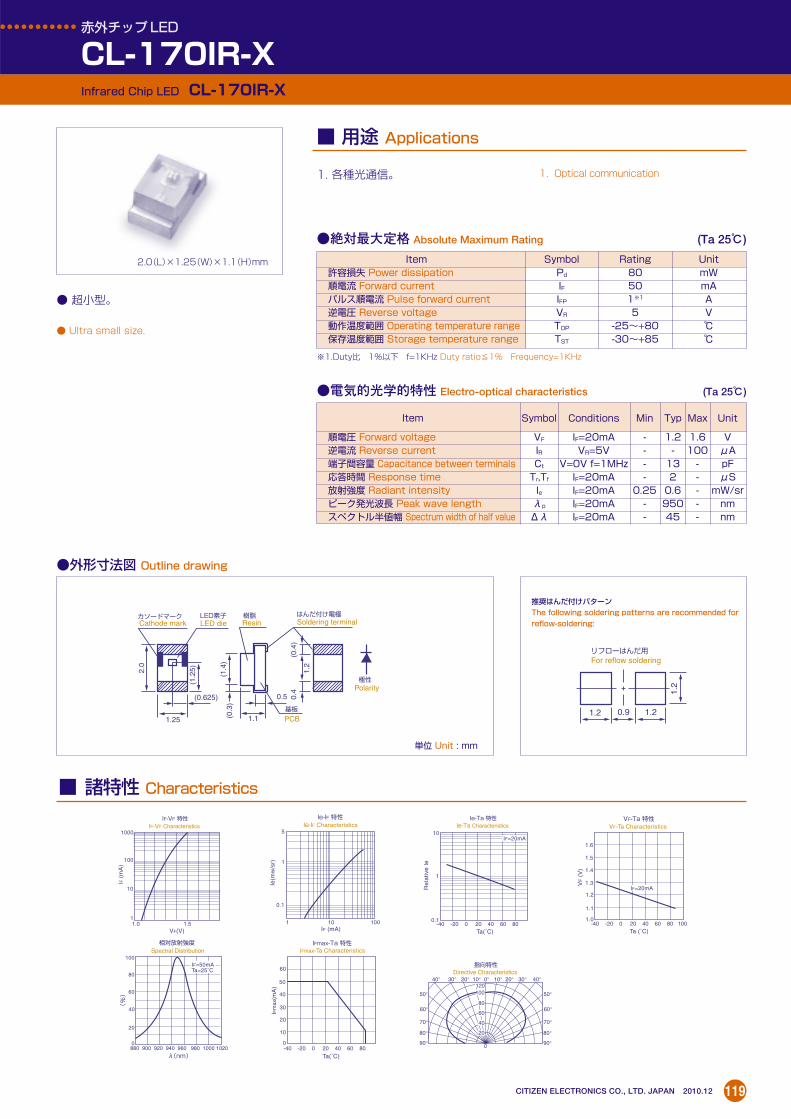
CL-170IR-XInfrared Chip LED CL-170IR-X
1. 各種光通信。
絶対最大定格 Absolute Maximum Rating (Ta 25)
電気的光学的特性 Electro-optical characteristics (Ta 25)
Item Symbol Rating Unit許容損失 Power dissipation Pd 80 mW順電流 Forward current IF 50 mAパルス順電流 Pulse forward current IFP 1※1 A逆電圧 Reverse voltage VR 5 V動作温度範囲 Operating temperature range TOP -25~+80 保存温度範囲 Storage temperature range TST -30~+85
※1.Duty比 1%以下 f=1KHz Duty ratio≦1% Frequency=1KHz
Item Symbol Conditions Min Typ Max Unit
順電圧 Forward voltage VF IF=20mA - 1.2 1.6 V逆電流 Reverse current IR VR=5V - - 100 μA端子間容量 Capacitance between terminals Ct V=0V f=1MHz - 13 - pF応答時間 Response time Tr,Tf IF=20mA - 2 - μS放射強度 Radiant intensity Ie IF=20mA 0.25 0.6 - mW/srピーク発光波長 Peak wave length λp IF=20mA - 950 - nmスペクトル半値幅 Spectrum width of half value Δλ IF=20mA - 45 - nm
用途 Applications
2.0(L)×1.25(W)×1.1(H)mm
1. Optical communication
超小型。
Ultra small size.
外形寸法図 Outline drawing
単位 Unit : mm
推奨はんだ付けパターンThe following soldering patterns are recommended for
reflow-soldering:
50°120100
80
60
40
20
60°
70°
80°
90°
50°
60°
70°
80°
90°
40° 30° 20° 10° 0° 10° 20° 30° 40°
指向特性 Directive Characteristics
50
60
40
20
30
0
10
IFmax-Ta 特性
VF-Ta 特性
IFmax-Ta Characteristics
-40 -20 0 20 40 60 80
-40 -20 0 20 40 60 80
-40 -20 0 20 40 60 80 100
10
1
0.1
Ta(˚C)
Ta(˚C)
Ie-Ta 特性 Ie-Ta Characteristics
Re
lativ
e le
IF (mA)
IFm
ax(m
A)
880 900 920 940 960 980 1000 1020
80
60
40
0
20
100
(%)
λ(nm)
Ie-IF 特性 Ie-IF Characteristics
IF=20mA
IF=20mA
0
1 10 100
5
1
0.1
Ie(m
w/s
r)
相対放射強度 Spectral Distribution
1.5
1.6
1.4
1.3
1.2
1.0
1.1
VF-Ta Characteristics
Ta (˚C)
VF (
V)
Ta=25˚CIF=50mA
1.0 1.5
1000
100
10
1
VF(V)
IF-VF 特性 IF-VF Characteristics
IF (
mA
)
LED素子 LED die
基板
PCB1.1
0.5
1.25
(0.625)
(1.4
)
(1.2
5)2.0
1.2
(0.3
)
(0.4
)
カソードマーク Cathode mark
極性
Polarity
はんだ付け電極 Soldering terminal
樹脂 Resin
0.4
0.9 1.21.2
1.2
リフローはんだ用 For reflow soldering
諸特性 Characteristics
120
CITIZEN ELECTRONICS CO., LTD. JAPAN 2010.12
赤外チップLED
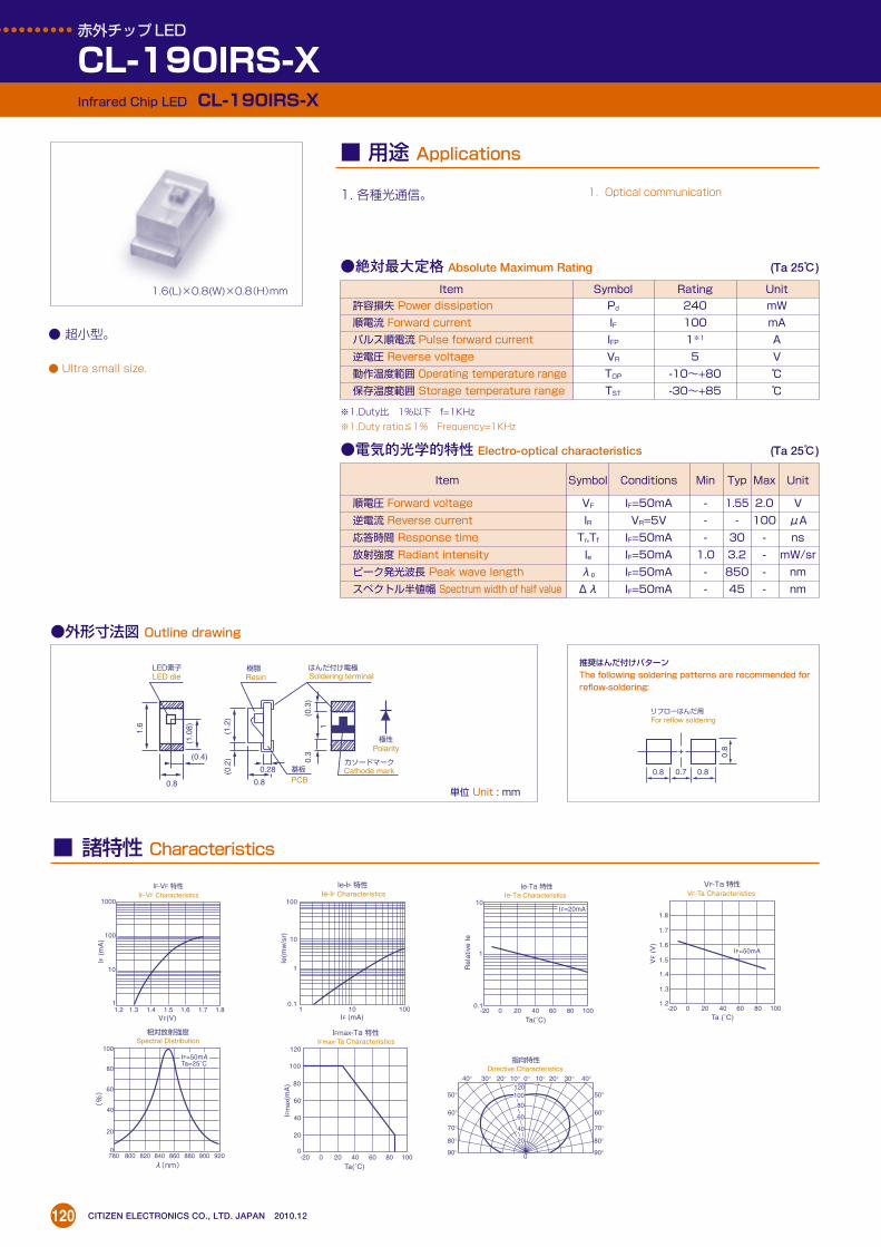
CL-190IRS-XInfrared Chip LED CL-190IRS-X
外形寸法図 Outline drawing
単位 Unit : mm
推奨はんだ付けパターン
The following soldering patterns are recommended forreflow-soldering:
1. 各種光通信。
絶対最大定格 Absolute Maximum Rating (Ta 25)
電気的光学的特性 Electro-optical characteristics (Ta 25)
Item Symbol Rating Unit
許容損失 Power dissipation Pd 240 mW
順電流 Forward current IF 100 mA
パルス順電流 Pulse forward current IFP 1※1 A
逆電圧 Reverse voltage VR 5 V
動作温度範囲 Operating temperature range TOP -10~+80
保存温度範囲 Storage temperature range TST -30~+85
※1.Duty比 1%以下 f=1KHz
※1.Duty ratio≦1% Frequency=1KHz
Item Symbol Conditions Min Typ Max Unit
順電圧 Forward voltage VF IF=50mA - 1.55 2.0 V
逆電流 Reverse current IR VR=5V - - 100 μA
応答時間 Response time Tr,Tf IF=50mA - 30 - ns
放射強度 Radiant intensity Ie IF=50mA 1.0 3.2 - mW/sr
ピーク発光波長 Peak wave length λp IF=50mA - 850 - nm
スペクトル半値幅 Spectrum width of half value Δλ IF=50mA - 45 - nm
Ie-IF 特性 Ie-IF Characteristics
VF-Ta 特性
-20 0 20 40 60 80 100
780 800 820 840 860 880 900 920
80
60
40
0
20
100
(%)
λ(nm)
IF=50mA
相対放射強度 Spectral Distribution
1.7
1.8
1.6
1.5
1.4
1.2
1.3
VF-Ta Characteristics
Ta (˚C)
VF (
V)
Ta=25˚CIF=50mA
1.2 1.3 1.4 1.5 1.6 1.7 1.8
1000
100
10
1
VF(V)
IF-VF 特性 IF-VF Characteristics
IF (
mA
)
-20 0 20 40 60 80 100
10
1
0.1
Ta(˚C)
Ie-Ta 特性 Ie-Ta Characteristics
Re
lativ
e le
IF=20mA
100
120
80
40
60
0
20
IFmax-Ta 特性 IFmax-Ta Characteristics
-20 0 20 40 60 80 100
Ta(˚C)
IFm
ax(m
A)
50°120100
80
60
40
20
60°
70°
80°
90°
50°
60°
70°
80°
90°
40° 30° 20° 10° 0° 10° 20° 30° 40°
指向特性 Directive Characteristics
0
IF (mA)1 10 100
100
10
1
0.1
Ie(m
w/s
r)
0.7 0.80.8
0.8
リフローはんだ用 For reflow soldering
LED素子 LED die
樹脂
基板
Resin
PCB0.8
0.28
(0.4)
0.8
0.3
1.6
(1.2
) (0.3
)
(1.0
8) 1
(0.2
) カソードマーク Cathode mark
極性 Polarity
はんだ付け電極 Soldering terminal
用途 Applications
1.6(L)×0.8(W)×0.8(H)mm
諸特性 Characteristics
1. Optical communication
超小型。
Ultra small size.

121
CITIZEN ELECTRONICS CO., LTD. JAPAN 2010.12
赤外チップLED
CL-330IRS-XInfrared Chip LED CL-330IRS-X
外形寸法図 Outline drawing
単位 Unit : mm
3.2 1.91.96.
0
リフローはんだ用
For reflow soldering
推奨はんだ付けパターンThe following soldering patterns are recommended for
reflow-soldering:
特徴/Features
1. データ通信用の送信用赤外光源。2. 各種光センサ用光源。
1. Infrared signal source for communicationsapplications.
2. IR light source for opto-sensors.
諸特性/Characteristics
絶対最大定格 Absolute Maximum Rating (Ta 25)
電気的光学的特性 Electro-optical Characteristics (Ta 25)
Item Symbol Rating Unit
許容損失 Power dissipation Pd 280 mW順電流 Forward current IF 130 mAパルス順電流 Pulse forward current IFP 1※1 A逆電圧 Reverse voltage VR 5 V動作温度範囲 Operating temperature range TOP -25~+80 保存温度範囲 Storage temperature range TST -30~+85
※1.Duty比 1%以下 f=1KHz Duty ratio≦1% Frequency=1KHz
Product code Radiant intensityVF(IF=50mA)
λP ΔλIe(IF=50mA)
TYP(V) MAX(V) (nm) (nm)MIN TYP
(mW/sr) (mW/sr))
CL-330IRS 赤外 Infrared 1.45 1.9 870 45 80 120
50°120100
80
60
40
20
60°
70°
80°
90°
50°
60°
70°
80°
90°
40° 30° 20° 10° 0° 10° 20° 30° 40°
指向特性 Directive Characteristics
T a(°C) T a(°C)-40 -25 0 20 40 60 80 100
1.8
1.9
1.7
1.6
1.5
1.4
1.3
1.2
VF-Ta 特性 VF-Ta Characteristics
1.2 1.3 1.4 1.5 1.6 1.7 1.8
1000
100
10
1
VF(V) IF(mA)
IF-VF 特性 IF-VF Characteristics
IF (
mA
)
CL-330IRS
VF (
V)
Ie-IF 特性 Ie-IF Characteristics
0
1 10 100 1000
1000
100
10
1
Ie(m
w/s
r)
T a(°C)
-40 -20 0 20 40 60 80 100
60
80
100
120
140
40
20
0
IFmax-Ta 特性 IFmax-Ta Characteristics
IFm
ax (
mA
)
-20 0 20 40 60 80
10
1
0.1
Ie-Ta 特性 Ie-Ta Characteristics
Rel
ativ
e Ie
用途 Applications
6.0(L)×6.0(W)×5.7(H)mm
諸特性 Characteristics
上面発光・高出力タイプ。
Top face emitting, high output type.
LED素子 LED die
基板 PCB
6 5.7
(3) (2.4) (1.5)3
6
(3) (1
.1)
(4.9
)
カソードマーク Cathode mark
極性※
Polarity
はんだ付け電極 Soldering terminal

122
CITIZEN ELECTRONICS CO., LTD. JAPAN 2010.12
フォトインタラプタ
CPI-210 SeriesPhoto-interrupter CPI-210 Series
外形寸法図 Outline drawing
単位 Unit : mm
推奨はんだ付けパターンThe following soldering patterns are recommended for
reflow-soldering:
IF-VF 特性 IF-VF Characteristics
50
100
20
10
5
2
11.0 1.2 1.4 1.6
VF(V)
IF(m
A)
- 40 0 40 80
1.6
1.5
1.3
1.4
1.2
1.0
0.9
1.1
VF-Ta 特性 VF-Ta Characteristics
T a(°C)
VF(V
)
-40 0 40 80
Ta(˚C)1 2 5 10 20 50 100
1000
500
200
100
20
50
10
IF(mA)
Ic-IF 特性 Ic-IF Characteristics
Ic(µ
A)
100
80
60
40
20
P(m
W)
120
140
PD,PC-Ta 特性 PD,PC-Ta Characteristics
出力(PC)
入力(PD)
IF=20mA
IF=5mA
1
2
4
3
① ①アノード
②
②カソード
④
④コレクタ ③
③エミッタ
①Anode②Cathode
④Collector③Emitter
5.0
2.0
A
A'
1.5 0.3
A-A'断面図
(1.0)
(0.5) (0.5)
1.0
4.0
4.0
1.0 1.
02.8
2.2
1.6
Section A-A'
3.0 2.02.0
0.6
1.6
1.6
リフローはんだ用 For reflow soldering
絶対最大定格 Absolute Maximum Rating (Ta 25)
Item Symbol Rating許容損失 Power dissipation (mW) PD 37.5順電流 Forward current (mA) IF 25
Inputパルス順電流 ※1 Pulse forward current ※1 (A) IFP 0.1逆電圧 Reverse voltage (V) VR 5コレクタ損失 Collector dissipation (mW) PC 75コレクタ電流 Collector current (mA) IC 20
Outputコレクターエミッタ間電圧 Voltage between collector and emitter (V) VCEO 20エミッターコレクタ間電圧 Voltage between emitter and collector (V) VECO 5
動作温度 Operating temperature range () Topr -30~+85保存温度 Storage temperature range () Tstg -40~+90
次の通り各種センサとして使用できます。1. CDプレーヤ及びフロッピーディスクドライブの位置検出用センサ。
2. プリンターヘッドの位置検出、カメラのフィルム検出用センサ。
3. カメラのレンズ駆動部の位置検出。
This can be used as a sensor in thefollowing applications.1. Position sensing for compact discplayers and floppy disc drives
2. Position sensing for printer heads orfilm in cameras
3. Position sensing for the lens drive unitof cameras
電気的光学的特性 Electro-optical characteristics (Ta 25)
※1 Duty: 1/100 、パルス幅0.1msec Duty: 1/100 , Pulse width: 0.1msec
Item Symbol Conditions Min Typ Max
順電圧 Forward voltage (V) VF IF=5mA - 1.1 1.3逆電流 Reverse current (μA) IR VR=5V - - 10
Input端子間容量 Capacitance between teminals (pF) Ct V=0V, f=1KHz - 30 -ピーク発光波長 Peak wave length (nm) λp IF=20mA - 940 -
暗電流 Collector dark current (μA) ICEO VCE=10V - - 0.1Output
結合光電流 Light current (μA) IC VCE=5V IF=5mA 50 150 (500)
特性Coupling 立上がり時間 Rise time (μsec) tr VCE=5V, IC=100μA - 10 -Characteristics 立下がり時間 Fall time (μsec) tf RL=1KΩ - 10 -
用途 Applications
5.0(L)×4.0(W)×4.0(H)mm
諸特性 Characteristics

123
CITIZEN ELECTRONICS CO., LTD. JAPAN 2010.12
フォトインタラプタ
CPI-250 SeriesPhoto-interrupter CPI-250 Series
外形寸法図 Outline drawing
単位 Unit : mm
推奨はんだ付けパターンThe following soldering patterns are recommended for
reflow-soldering:
受光素子を2個搭載したことにより、位相差検出が可能となりました。
Mounting of two photoreceptor elementsallows differential position sensing.
絶対最大定格 Absolute Maximum Rating (Ta 25)
Item Symbol Rating許容損失 Power dissipation (mW) PD 37.5
入力 順電流 Forward current (mA) IF 25Input パルス順電流 ※1 Pulse forward current ※1 (A) IFP 0.1
逆電圧 Reverse voltage (V) VR 5コレクタ損失 Collector dissipation (mW) PC 75
出力 コレクタ電流 Collector current (mA) IC 20Output コレクターエミッタ間電圧 Voltage between collector and emitter (V) VCEO 20
エミッターコレクタ間電圧 Voltage between emitter and collector (V) VECO 5動作温度 Operating temperature range () Topr -30~+85保存温度 Storage temperature range () Tstg -40~+90
次の通り各種センサとして使用できます。1. マウスのボール回転検出。2. 各種エンコーダーの検出。
This can be used as a sensor in thefollowing applications.1. Rotation sensing for mouse balls2. Sensing for various types of encoderapplications
電気的光学的特性 Electro-optical characteristics (Ta 25)
※1 Duty: 1/100 、パルス幅0.1msec Duty: 1/100, Pulse width: 0.1msec
Item Symbol Conditions Min Typ Max
順電圧 Forward voltage (V) VF IF=5mA - 1.1 1.3逆電流 Reverse current (μA) IR VR=5V - - 10
Input端子間容量 Capacitance between teminals (pF) Ct V=0V, f=1KHz - 30 -ピーク発光波長 Peak wave length (nm) λp IF=20mA - 940 -
暗電流 Collector dark current (μA) ICEO VCE=10V - - 0.1Output
結合光電流 Light current (μA)
IC1 VCE=5V IF=5mA50 150 (500)
特性 IC2 VCE=5V IF=5mACoupling 立上がり時間 Rise time (μsec) tr VCE=5V, IC=100μA - 10 -Characteristics 立下がり時間 Fall time (μsec) tf RL=1KΩ - 10 -
IF-VF 特性 IF-VF Characteristics
50
100
20
10
5
2
11.0 1.2 1.4 1.6
VF(V)
IF(m
A)
- 40 0 40 80
1.6
1.5
1.3
1.4
1.2
1.0
0.9
1.1
VF-Ta 特性 VF-Ta Characteristics
T a(°C)
VF(V
)
-40 0 40 80
Ta(˚C)1 2 5 10 20 50 100
1000
500
200
100
20
50
10
IF(mA)
Ic-IF 特性 Ic-IF Characteristics
Ic(µ
A)
100
80
60
40
20
P(m
W)
120
140
PD,PC-Ta 特性 PD,PC-Ta Characteristics
出力(PC)
入力(PD)
IF=20mA
IF=5mA
1
2
3
6
5
4
① ①アノード
② ③カソード
④
⑤
⑥
⑥コレクタ ③
④エミッタ2
①Anode③Cathode
⑥Collector
④Emitter2⑤エミッタ1⑤Emitter1
5.0
2.0
A
A'
1.5 0.30.8
A-A'断面図
(1.0)
(0.5) (0.5)
1.0
4.0
4.0
1.0 1.
12.8
1.4
1.4
1.0
Section A-A'
0.4
0.4
2.0 3.0 2.0
1.0
1.0
1.0
リフローはんだ用 For reflow soldering
用途 Applications
5.0(L)×4.0(W)×4.0(H)mm
諸特性 Characteristics

124
CITIZEN ELECTRONICS CO., LTD. JAPAN 2010.12
搬送周波数 Carrier frequency 仕様 SpecificationsSeries Feature
40KHz 38KHz 36.7KHzフォトダイオードサイズ 到達距離Size of photo-diode Reaching distance
高感度8m以上
RS-20 Series For high RS-20 RS-21 RS-22 3mm8 meters min.sensitivity
汎用5m以上
RS-30 Series For general RS-30 RS-31 RS-32 2mm5 meters min.purpose
側面受光用5m以上
RS-50 Series For side-mounted RS-50 RS-51 RS-52 2mm5 meters min.receiver
赤外線リモートコントロール受光ユニット
RS-20, RS-30, RS-50 SeriesInfrared Remote Control Receiver Unit RS-20, RS-30, RS-50 Series
単位 Unit : mm
推奨はんだ付けパターンThe following soldering patterns are recommended for
reflow-soldering:
GND1
1.6
1.7
1.7
1.6
1.6
1.7
1.5
2.0
2.2 2.8 2.8 2.2
(注)リモコン受光ユニット(RS)下面は、ベタアースとする。
(Note)Remote control receiver unit (RS) should be
grounded wholly on its bottom side.
RS-20、30シリーズ RS-20, 30 Series
TV、VTR、オーディオ機器、エアコン、カーステレオ、カメラ、その他
TV, VCR, audio equipment, air conditioner,automotive equipment, camera etc.
絶対最大定格 Absolute Maximum Rating (Ta 25)
Item Symbol Rating Unit
電源電圧 Power supply voltage V 6 V
動作温度範囲 Operating temperature range TOP -30~+85 保存温度範囲 Storage temperature range TST -40~+90
動作電圧 Recommended Operating Conditions推奨動作範囲
Item SymbolRecommended Operating Voltage
Unit
電源圧力 Power voltage VCC 4.5~5.5 V
仕様 Specifications
内部結線部 Internal circuit diagram
GND1
GND
C2
Cd
OUT
Vcc
VccRs
R1
fo4 3 1
2
657
8 B TP RF A+ P
ABLC
IN-
C1
P-DiA
K
TP1IN+
GND2
TP2
リモコン用ICIC for remote control
初段アンプ Pre-amplifier
リミッタ Limiter
検波 Wave rectifying
波形整形 Wave form shaping
RL 33kΩ ±25%
RS-20.30
外形寸法図 Outline drawing
RS-50
RS-50シリーズは、RS-750シリーズと同一 RS-50 Series identical to RS-750 Series
用途 Applications
7.7(L)×8.1(W)×3.5(H)mm
4.0(L)×9.2(W)×5.0(H)mm
8.1
1.0
TP-2
4-R0.4
0.7 6.1
TP-1
3.5
1.4
7.7
5.0
1.6
Vcc
OUT
CASE GND
GND1
GND2
TOP VIEW
4X5
受光中心
Center of photo-diode
超小型。
Ultra small size.

125CITIZEN ELECTRONICS CO., LTD. JAPAN 2010.12
電気的特性(RS-20) Electrical characteristics (RS-20) (Vcc 5.0V,Ta 25)
(注1) 下図に示すバースト波を標準送信機にて送信するものとします。
(Note 1)Burst waves as shown below are transmitted from standard transmitters.
(注2) 光学的測定は外乱光及び反射物のない場所(暗闇)で行うものとします。
(Note 2) Optical measurements should be conducted at dark locations where light disturbances and
reflective objects are not present.
Conditions
無信号入力時においてWhen no signal is put in
光軸において(注1)(注2)At optical axis(Note 1)(Note 2)受光面を頂点として光軸に対して30°の円錐形の範囲においてWithin the range of 30°circularcone to optical axis at the topsurface of photo sensor window受光面を頂点として光軸に対して45°の円錐形の範囲においてWithin the range of 45°circularcone to optical axis at the topsurface of photo sensor window光軸上30cmの距離において(注1)At distance of 30 cm on opticalaxis (Note 1)
光軸上30cmの距離において(注1)At distance of 30 cm on opticalaxis (Note 1)
5cmから到達距離までの範囲において出力のTWL期間幅で規定(注1)To be determined based on theoutput TWL time required withinthe range from 5 cm to thereaching distance (Note 1)
Symbol
ICC
L0
L30
L45
VL
VH
TWL
f0
Items
消費電流Currentconsumption
到達距離Reachingdistance
Lowレベル出力電圧Low leveloutput voltageHighレベル出力電圧High leveloutput voltageLowレベルパルス幅Low levelpulsewidth
搬送周波数Carrierfrequency
No
1
2
3
4
5
6
Minimum Typical Maximum
- 2.1 2.8
8 10 -
5 7 -
3.5 5 -
- 0.2 0.4
4.8 5 -
400 600 800
- 40 -
Unit
mA
m
V
V
μs
KHz
指向図 Directive diagram
fo
600µS 600µS
20
40
60
80
100
-60°
-75°
-90°
60°
75°
90°
-45° -30° -15° 0° 15° 30° 45°
指向特性 Directive Characteristics
RS-20,30,50 シリーズ
RS-20,30,50 Series

126
CITIZEN ELECTRONICS CO., LTD. JAPAN 2010.12
赤外線リモートコントロール受光ユニット
RS-450 SeriesInfrared Remote Control Receiver Unit RS-450 Series
外形寸法図 Outline drawing
単位 Unit : mm
推奨はんだ付けパターン
The following soldering patterns are recommended forreflow-soldering:
RS-450シリーズ RS-450Series
TV、VTR、オーディオ機器、エアコン、カーステレオ、カメラ、その他
TV, VCR, audio equipment, air conditioner,automotive equipment, camera etc.
絶対最大定格 Absolute Maximum Rating (Ta 25)
Item Symbol Rating Unit電源電圧 Power supply voltage V 6 V動作温度範囲 Operating temperature range TOP -30~+85 保存温度範囲 Storage temperature range TST -40~+90
動作電圧 Recommended Operating Conditions推奨動作範囲
Item SymbolRecommended Operating Voltage
Unit
電源圧力 Power voltage VCC 2.7~5.5 V
仕様 Specifications搬送周波数 Carrier frequency 仕様 Specifications
Series Feature40KHz 38KHz 36.7KHz
フォトダイオードサイズ 到達距離Size of photo-diode Reaching distance
側面受光用5m以上
RS-450 Series For side-mounted RS-450 RS-451 RS-452 1.78mm5 meters min.receiver
内部結線部 Internal circuit diagram
GND
OUT
Vcc
1
5
42
3入力回路
Input Stage
出力回路
Output Circuit
アンプフィルター回路 Amplifier +
バンドパスフィルター B.P.F
AGC回路/ATC回路 AGC Circuit ATC Circuit
+ 制御回路
Control Circuit
発振回路
Oscillator
30kΩ
用途 Applications
2.65(L)×7.5(W)×2.75(H)mm
受光中心 Light receiving center
ケース GND(2箇所) Case GND(two places)
(3.75)
2.65
2.3
12.7
7
2.8
1.20.4
0.7
1.25
2.2
2.651.750.225
7.5
0.35
0.975
1.4
1.0
0.45
2.752.6
(1.1
)
マウント中心 Mounting center
1.9 2.1 1.21.5② ③ ①
①GND ②Vcc ③OUT
(注)リモコン受光ユニット(RS)下面は、ベタアースとする。
(Note)Remote control receiver unit (RS) should be
grounded wholly on its bottom side.
0.85
0.95
0.36 1.3
(6.8)
2.1 1.35 2.05 1.3
0.753 3
0.75
(7.5)
(2.4
)
2.2
(4)
0.2
ベタアース Grounded wholly
マウント中心 Mounting center
超小型。
Ultra small size.

127CITIZEN ELECTRONICS CO., LTD. JAPAN 2010.12
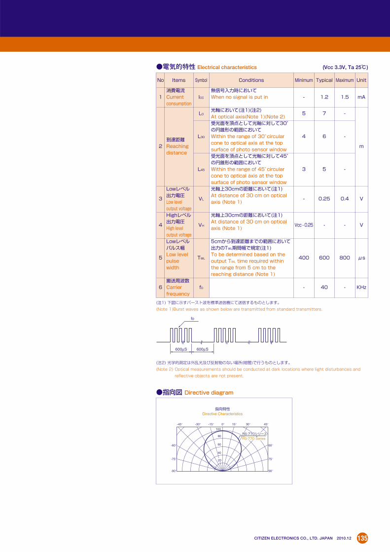
電気的特性 Electrical characteristics (Vcc 3.3V, Ta 25)
(注1) 下図に示すバースト波を標準送信機にて送信するものとします。
(Note 1)Burst waves as shown below are transmitted from standard transmitters.
(注2) 光学的測定は外乱光及び反射物のない場所(暗闇)で行うものとします。
(Note 2) Optical measurements should be conducted at dark locations where light disturbances and
reflective objects are not present.
Conditions
無信号入力時においてWhen no signal is put in
光軸において(注1)(注2)At optical axis(Note 1)(Note 2)受光面を頂点として光軸に対して30°の円錐形の範囲においてWithin the range of 30°circularcone to optical axis at the topsurface of photo sensor window受光面を頂点として光軸に対して45°の円錐形の範囲においてWithin the range of 45°circularcone to optical axis at the topsurface of photo sensor window光軸上30cmの距離において(注1)At distance of 30 cm on opticalaxis (Note 1)
光軸上30cmの距離において(注1)At distance of 30 cm on opticalaxis (Note 1)
5cmから到達距離までの範囲において出力のTWL期間幅で規定(注1)To be determined based on theoutput TWL time required withinthe range from 5 cm to thereaching distance (Note 1)
Symbol
ICC
L0
L30
L45
VL
VH
TWL
f0
Items
消費電流Currentconsumption
到達距離Reachingdistance
Lowレベル出力電圧Low leveloutput voltageHighレベル出力電圧High leveloutput voltageLowレベルパルス幅Low levelpulsewidth
搬送周波数Carrierfrequency
No
1
2
3
4
5
6
Minimum Typical Maximum
- 1.2 1.5
5 7 -
4 6 -
3 5 -
- 0.25 0.4
Vcc - 0.25 - -
400 600 800
- 40 -
Unit
mA
m
V
V
μs
KHz
指向図 Directive diagram
fo
600µS 600µS
20
40
60
80
100
-60°
-75°
-90°
60°
75°
90°
-45° -30° -15° 0° 15° 30° 45°
指向特性 Directive Characteristics
RS-450シリーズ
RS-450 Series

128
CITIZEN ELECTRONICS CO., LTD. JAPAN 2010.12
赤外線リモートコントロール受光ユニット
RS-470 SeriesInfrared Remote Control Receiver Unit RS-470 Series
外形寸法図 Outline drawing
単位 Unit : mm
推奨はんだ付けパターン
The following soldering patterns are recommended forreflow-soldering:
RS-470シリーズ RS-470Series
TV、VTR、オーディオ機器、エアコン、カーステレオ、カメラ、その他
TV, VCR, audio equipment, air conditioner,automotive equipment, camera etc.
絶対最大定格 Absolute Maximum Rating (Ta 25)
Item Symbol Rating Unit電源電圧 Power supply voltage V 6 V動作温度範囲 Operating temperature range TOP -30~+85 保存温度範囲 Storage temperature range TST -40~+90
動作電圧 Recommended Operating Conditions推奨動作範囲
Item SymbolRecommended Operating Voltage
Unit
電源圧力 Power voltage VCC 2.7~5.5 V
仕様 Specifications搬送周波数 Carrier frequency 仕様 Specifications
Series Feature40KHz 38KHz 36.7KHz
フォトダイオードサイズ 到達距離Size of photo-diode Reaching distance
超小型 5m以上RS-470 Series
Ultra smallRS-470 RS-471 RS-472 1.78mm
5 meters min.
内部結線部 Internal circuit diagram
GND
OUT
Vcc
1
5
42
3入力回路
Input Stage
出力回路
Output Circuit
アンプフィルター回路 Amplifier +
バンドパスフィルター B.P.F
AGC回路/ATC回路 AGC Circuit ATC Circuit
+ 制御回路
Control Circuit
発振回路
Oscillator
30kΩ
用途 Applications
3.1(L)×4.25(W)×1.1(H)mm
Vcc
GNDOUT
GND
4 X 5
4.25
(1.95)
1.67
0.65
0.65
0.28
3.1
3.99
1.1
2.84
2.1
(注)リモコン受光ユニット(RS)下面は、ベタアースとする。
(Note)Remote control receiver unit (RS) should be
grounded wholly on its bottom side.
1.2
3.94
1.2
5.09
ベタアース Grounded wholly
超小型。
Ultra small size.

129CITIZEN ELECTRONICS CO., LTD. JAPAN 2010.12
電気的特性 Electrical characteristics (Vcc 3.3V, Ta 25)
(注1) 下図に示すバースト波を標準送信機にて送信するものとします。
(Note 1)Burst waves as shown below are transmitted from standard transmitters.
(注2) 光学的測定は外乱光及び反射物のない場所(暗闇)で行うものとします。
(Note 2) Optical measurements should be conducted at dark locations where light disturbances and
reflective objects are not present.
Conditions
無信号入力時においてWhen no signal is put in
光軸において(注1)(注2)At optical axis(Note 1)(Note 2)受光面を頂点として光軸に対して30°の円錐形の範囲においてWithin the range of 30°circularcone to optical axis at the topsurface of photo sensor window受光面を頂点として光軸に対して45°の円錐形の範囲においてWithin the range of 45°circularcone to optical axis at the topsurface of photo sensor window光軸上30cmの距離において(注1)At distance of 30 cm on opticalaxis (Note 1)
光軸上30cmの距離において(注1)At distance of 30 cm on opticalaxis (Note 1)
5cmから到達距離までの範囲において出力のTWL期間幅で規定(注1)To be determined based on theoutput TWL time required withinthe range from 5 cm to thereaching distance (Note 1)
Symbol
ICC
L0
L30
L45
VL
VH
TWL
f0
Items
消費電流Currentconsumption
到達距離Reachingdistance
Lowレベル出力電圧Low leveloutput voltageHighレベル出力電圧High leveloutput voltageLowレベルパルス幅Low levelpulsewidth
搬送周波数Carrierfrequency
No
1
2
3
4
5
6
Minimum Typical Maximum
- 1.2 1.5
5 7 -
4 6 -
3 5 -
- 0.25 0.4
Vcc - 0.25 - -
400 600 800
- 40 -
Unit
mA
m
V
V
μs
KHz
指向図 Directive diagram
fo
600µS 600µS
20
40
60
80
100
-60°
-75°
-90°
60°
75°
90°
-45° -30° -15° 0° 15° 30° 45°
指向特性 Directive Characteristics
RS-470シリーズ
RS-470 Series

130
CITIZEN ELECTRONICS CO., LTD. JAPAN 2010.12
赤外線リモートコントロール受光ユニット
RS-670 SeriesInfrared Remote Control Receiver Unit RS-670 Series
外形寸法図 Outline drawing
単位 Unit : mm
推奨はんだ付けパターンThe following soldering patterns are recommended for
reflow-soldering:
(注)リモコン受光ユニット(RS)下面は、ベタアースとする。
(Note)Remote control receiver unit (RS) should be
grounded wholly on its bottom side.
1.6
2.5
1.6
2.0
2.1
1.6
1.6 3.0 1.6
2.2
RS-670シリーズ RS-670Series
用途/Application
TV、VTR、オーディオ機器、エアコン、カーステレオ、カメラ、その他
TV, VCR, audio equipment, air conditioner,automotive equipment, camera etc.
絶対最大定格 Absolute Maximum Rating (Ta 25)
Item Symbol Rating Unit電源電圧 Power supply voltage V 6 V動作温度範囲 Operating temperature range TOP -30~+85 保存温度範囲 Storage temperature range TST -40~+90
動作電圧 Recommended Operating Conditions推奨動作範囲
Item SymbolRecommended Operating Voltage
Unit
電源圧力 Power voltage VCC 4.5~5.5 V
仕様 Specifications搬送周波数 Carrier frequency 仕様 Specifications
Series Feature40KHz 38KHz 36.7KHz
フォトダイオードサイズ 到達距離Size of photo-diode Reaching distance
汎用5m以上
RS-670 Series For general RS-670 RS-671 RS-672 2mm5 meters min.purpose
内部結線部 Internal circuit diagram
GND
OUT
Vcc1
2
3
4
初段アンプ First stage amplifier
リミッタ Limiter amplifier
波形成形 Wave form shaping circuit
キャリア除去回路 Carrier elimination
AGCABLC
TRAP
TRAP
Skip
Trimming
circuitfo setting
BPF DetectorIN
22kΩ
用途 Applications
4.5(L)×5.0(W)×1.35(H)mm
Vcc
OUT GND
GND
4 X 5
5.0
2.45
2.2
4.5
1.32
1.35(ケース Case)
2.5
0.85
0.85
3.00.85 0.85
4-R0.55
超小型。
Ultra small size.

131CITIZEN ELECTRONICS CO., LTD. JAPAN 2010.12
電気的特性 Electrical characteristics (Vcc 5.0V, Ta 25)
(注1) 下図に示すバースト波を標準送信機にて送信するものとします。
(Note 1)Burst waves as shown below are transmitted from standard transmitters.
(注2) 光学的測定は外乱光及び反射物のない場所(暗闇)で行うものとします。
(Note 2) Optical measurements should be conducted at dark locations where light disturbances and
reflective objects are not present.
Conditions
無信号入力時においてWhen no signal is put in
光軸において(注1)(注2)At optical axis(Note 1)(Note 2)受光面を頂点として光軸に対して30°の円錐形の範囲においてWithin the range of 30°circularcone to optical axis at the topsurface of photo sensor window受光面を頂点として光軸に対して45°の円錐形の範囲においてWithin the range of 45°circularcone to optical axis at the topsurface of photo sensor window光軸上30cmの距離において(注1)At distance of 30 cm on opticalaxis (Note 1)
光軸上30cmの距離において(注1)At distance of 30 cm on opticalaxis (Note 1)
5cmから到達距離までの範囲において出力のTWL期間幅で規定(注1)To be determined based on theoutput TWL time required withinthe range from 5 cm to thereaching distance (Note 1)
Symbol
ICC
L0
L30
L45
VL
VH
TWL
f0
Items
消費電流Currentconsumption
到達距離Reachingdistance
Lowレベル出力電圧Low leveloutput voltageHighレベル出力電圧High leveloutput voltageLowレベルパルス幅Low levelpulsewidth
搬送周波数Carrierfrequency
No
1
2
3
4
5
6
Minimum Typical Maximum
- 1.6 -
5 7 -
3 5 -
2.5 3.5 -
- 0.2 0.4
4.8 5 -
400 600 800
- 40 -
Unit
mA
m
V
V
μs
KHz
指向図 Directive diagram
fo
600µS 600µS
20
40
60
80
100
-60°
-75°
-90°
60°
75°
90°
-45° -30° -15° 0° 15° 30° 45°
指向特性 Directive Characteristics
RS-670シリーズ
RS-670 Series

132
CITIZEN ELECTRONICS CO., LTD. JAPAN 2010.12
指向図 Directive diagram
20
40
60
80
100
120
60°
45°
75°
90°
60°
45°
75°
90°
30° 15° 0° 15° 30°
指向特性 Directive Characteristics
RS-780 シリーズ RS-780 Series
RS-750,790 シリーズ
RS-750,790 Series
赤外線リモートコントロール受光ユニット
RS-750, RS-780, RS-790 SeriesInfrared Remote Control Receiver Unit RS-750, RS-780, RS-790 Series
超小型。 RS-750シリーズは、低電圧タイプの受光ユニットです。
RS-780シリーズは、レンズ付きで受光距離特性が優れています。
RS-790シリーズは、RS-770シリーズより製品高さを必要とするアプリケーション用です。
Ultra small size. The RS-750 series are low voltage typesensors.
The RS-780 series with lenses provide excellentsensing distance characteristics.
The application of the RS-790 series is suitablefor thicker products compared with those of theRS-770 series.
TV、VTR、オーディオ機器、エアコン、カーステレオ、カメラ、その他
TV, VCR, audio equipment, air conditioner,automotive equipment, camera etc.
絶対最大定格 Absolute Maximum Rating (Ta 25)
Item Symbol Rating Unit
電源電圧 Power supply voltage V 6 V
動作温度範囲 Operating temperature range TOP -30~+85
保存温度範囲 Storage temperature range TST -40~+90
動作電圧 Recommended Operating Conditions推奨動作範囲
Item SymbolRecommended Operating Voltage
Unit
電源圧力 Power voltage Vcc 2.7~5.5 V
( )
仕様 Specifications
搬送周波数 Carrier frequency 仕様 SpecificationsSeries Feature
40KHz 38KHz 36.7KHz フォトダイオードサイズ 到達距離Size of photo-diode Reaching distance
側面受光用 5m以上RS-750 Series For side-mounted RS-750 RS-751 RS-752 2mm
5 meters min.receiver
汎用 2mm 5m以上RS-780 Series For general RS-780 RS-781 RS-782 レンズ付
5 meters min.purpose with lens
汎用 5m以上RS-790 Series For general RS-790 RS-791 RS-792 2mm
5 meters min.purpose
内部結線図 Internal circuit diagram
RS-750
RS-780
RS-790
GND
OUT
Vcc
1
5
42
3入力回路
Input Stage
出力回路
Output Circuit
アンプフィルター回路 Amplifier +
バンドパスフィルター B.P.F
AGC回路/ATC回路 AGC Circuit ATC Circuit
+ 制御回路
Control Circuit
発振回路
Oscillator
30kΩ
用途 Applications
4.0(L)×9.2(W)×5.0(H)mm
5.25(L)×8.3(W)×3.0(H)mm
5.5(L)×7.4(W)×2.55(H)mm

133CITIZEN ELECTRONICS CO., LTD. JAPAN 2010.12
2.05
2.2 3.0 2.2
0.6
1.22
51.
225 5.
5
0.15
2.15
5.1
4-R0.8
R0.5
GND
GND
Vcc
1.1 1.1
7.4
0.95
2.55
OUT
5.1
2-R0.6
GND
4X5
1.55
0.95
1.4
5
1.6
1.95.5
1.6
1.6
2.55
Minimum Typical Maximum Unit
- 1.2 1.5 mA
5 7 -
4 6 -m
3 5 -
- 0.25 0.4 V
Vcc-0.25 - - V
400 600 800 μs
- 40 - KHz
Conditions
無信号入力時においてWhen no signal is put in
光軸において(注1)(注2)At optical axis(Note 1)(Note 2)
受光面を頂点として光軸に対して30 ˚の円錐形の範囲においてWithin the range of 30°circular cone to opticalaxis at the top surface of photo sensor window
受光面を頂点として光軸に対して45 ˚の円錐形の範囲においてWithin the range of 45°circular cone to opticalaxis at the top surface of photo sensor window
光軸上30cmの距離において(注1)At distance of 30 cm on optical axis(Note 1)
光軸上30cmの距離において(注1)At distance of 30 cm on optical axis(Note 1)
5 c mから到達距離までの範囲において出力のTWL期間幅で規定(注1)To be determined based on the output TWLtime required within the range from 5 cm tothe reaching distance (Note 1)
Symbol
ICC
L0
L30
L45
VL
VH
TWL
f0
Item
消費電流Currentconsumption
到達距離Reachingdistance
Lowレベル出力電圧Low leveloutput voltageHighレベル出力電圧High leveloutput voltageLowレベルパルス幅Low levelpulsewidth搬送周波数Carrierfrequency
No
1
2
3
4
5
6
電気的特性(RS-790) Electrical characteristics(RS-790) (Vcc 3.3V)(Ta 25)
(注1) 下図に示すバースト波を標準送信機にて送信するものとします。
(Note 1)Burst waves as shown below are transmitted from
standard transmitters.
(注2) 光学的測定は外乱光及び反射物のない場所(暗闇)で行うもの
とします。
(Note 2) Optical measurements should be conducted at
dark locations where light disturbances and reflective
objects are not present.
fo
600µS 600µS
推奨はんだ付けパターンThe following soldering patterns are recommended forreflow-soldering:
RS-790シリーズ RS-790 Series
推奨はんだ付けパターンThe following soldering patterns are recommended forreflow-soldering:
RS-780シリーズ RS-780 Series
外形寸法図 Outline drawing
5.25
1.0
3.5
ø2.
2
GND
GNDVcc
7.6 1.83.08.3
1.0 R0.5
OUT
4X5
1.6 5.8 1.6
1.6
3.
2
1.6
(注)リモコン受光ユニット(RS)下面は、ベタアースとする。
(Note)Remote control receiver unit (RS) should be
grounded wholly on its bottom side.
3.0 3.0 3.0
2.6
1.9
2.
6
(注)リモコン受光ユニット(RS)下面は、ベタアースとする。
(Note)Remote control receiver unit (RS) should be
grounded wholly on its bottom side.
RS-750シリーズ RS-750 Series
8.1
3.8
4.0
(2places)
9.2
2.15 1.6
3.1 5.
0
0.7
R0.3
GNDVCCOUT
2.5 2.5
4X5
受光中心 Center of photo-diode
Case GND(2ヶ所)
1
1
2
2
3
3
単位 Unit : mm単位 Unit : mm
推奨はんだ付けパターンThe following soldering patterns are recommended forreflow-soldering:
1.8
2.0
2.5 2.5
4.5 4.5
1.4
2.0 2.
21.
4
マウント中心 Center of mounting
ベタアース Grounded wholly
(注)リモコン受光ユニット(RS)下面は、ベタアースとする。
(Note)Remote control receiver unit (RS) should be
grounded wholly on its bottom side.
単位 Unit : mm

134
CITIZEN ELECTRONICS CO., LTD. JAPAN 2010.12
赤外線リモートコントロール受光ユニット
RS-770 SeriesInfrared Remote Control Receiver Unit RS-770 Series
外形寸法図 Outline drawing
単位 Unit : mm
推奨はんだ付けパターン
The following soldering patterns are recommended forreflow-soldering:
(注)リモコン受光ユニット(RS)下面は、ベタアースとする。
(Note)Remote control receiver unit (RS) should be
grounded wholly on its bottom side.
1.6
2.5
1.6
2.0
2.1
1.6
1.6 3.0 1.6
2.2
RS-770シリーズ RS-770Series
TV、VTR、オーディオ機器、エアコン、カーステレオ、カメラ、その他
TV, VCR, audio equipment, air conditioner,automotive equipment, camera etc.
絶対最大定格 Absolute Maximum Rating (Ta 25)
Item Symbol Rating Unit電源電圧 Power supply voltage V 6 V動作温度範囲 Operating temperature range TOP -30~+85 保存温度範囲 Storage temperature range TST -40~+90
動作電圧 Recommended Operating Conditions推奨動作範囲
Item SymbolRecommended Operating Voltage
Unit
電源圧力 Power voltage VCC 2.7~5.5 V
仕様 Specifications搬送周波数 Carrier frequency 仕様 Specifications
Series Feature40KHz 38KHz 36.7KHz
フォトダイオードサイズ 到達距離Size of photo-diode Reaching distance
汎用5m以上
RS-770 Series For general RS-770 RS-771 RS-772 2mm5 meters min.purpose
内部結線部 Internal circuit diagram
GND
OUT
Vcc
1
5
42
3入力回路
Input Stage
出力回路
Output Circuit
アンプフィルター回路 Amplifier +
バンドパスフィルター B.P.F
AGC回路/ATC回路 AGC Circuit ATC Circuit
+ 制御回路
Control Circuit
発振回路
Oscillator
30kΩ
用途 Applications
4.5(L)×5.0(W)×1.35(H)mm
Vcc
OUT GND
GND
4 X 5
5.0
2.45
2.2
4.5
2.5
0.85
0.85
3.00.85 0.85
4-R0.55
1.32
1.35(ケース Case)
超小型。
Ultra small size.
135CITIZEN ELECTRONICS CO., LTD. JAPAN 2010.12
電気的特性 Electrical characteristics (Vcc 3.3V, Ta 25)
(注1) 下図に示すバースト波を標準送信機にて送信するものとします。
(Note 1)Burst waves as shown below are transmitted from standard transmitters.
(注2) 光学的測定は外乱光及び反射物のない場所(暗闇)で行うものとします。
(Note 2) Optical measurements should be conducted at dark locations where light disturbances and
reflective objects are not present.
Conditions
無信号入力時においてWhen no signal is put in
光軸において(注1)(注2)At optical axis(Note 1)(Note 2)受光面を頂点として光軸に対して30°の円錐形の範囲においてWithin the range of 30°circularcone to optical axis at the topsurface of photo sensor window受光面を頂点として光軸に対して45°の円錐形の範囲においてWithin the range of 45°circularcone to optical axis at the topsurface of photo sensor window光軸上30cmの距離において(注1)At distance of 30 cm on opticalaxis (Note 1)
光軸上30cmの距離において(注1)At distance of 30 cm on opticalaxis (Note 1)
5cmから到達距離までの範囲において出力のTWL期間幅で規定(注1)To be determined based on theoutput TWL time required withinthe range from 5 cm to thereaching distance (Note 1)
Symbol
ICC
L0
L30
L45
VL
VH
TWL
f0
Items
消費電流Currentconsumption
到達距離Reachingdistance
Lowレベル出力電圧Low leveloutput voltageHighレベル出力電圧High leveloutput voltageLowレベルパルス幅Low levelpulsewidth
搬送周波数Carrierfrequency
No
1
2
3
4
5
6
Minimum Typical Maximum
- 1.2 1.5
5 7 -
4 6 -
3 5 -
- 0.25 0.4
Vcc - 0.25 - -
400 600 800
- 40 -
Unit
mA
m
V
V
μs
KHz
指向図 Directive diagram
fo
600µS 600µS
20
40
60
80
100
-60°
-75°
-90°
60°
75°
90°
-45° -30° -15° 0° 15° 30° 45°
指向特性 Directive Characteristics
RS-770シリーズ
RS-770 Series

136
CITIZEN ELECTRONICS CO., LTD. JAPAN 2010.12
フォトリフレクタ
PR-30Photo-reflector PR-30
次の通り各種センサとして使用できます。1. カメラモジュールのレンズ位置検出用センサ。
2. ビデオ、オーディオ・テープのスタート、エンドマーク検出用センサ。
3. ビデオ、オーディオテープのリール回転検出用センサ。
4. CDプレーヤの位置検出センサ。5. 複写機、プリンター等の紙検出、タイミング検出用センサ。
This can be used as a sensor in thefollowing applications.1. Lens position sensing for cameramodules.
2. Start and end mark sensing for VCRand audio tapes
3. Reel rotation sensing for VCR andaudio tapes
4. Position sensing for compact discplayers
5. Position and timing sensing for copyingmachines and printers
測定方法 Measuring method
用途 Applications
2.18(L)×1.9(W)×0.75(H)mm
諸特性 Characteristics
超小型・薄型。 検出距離は約1mmであり高精度な位置検出が可能です。
可視光カット樹脂の採用により、外乱光による誤動作を防止できます。
Thin and micro-size. The detectable distance of approx. 1 mm enablesposition sensing to be of high accuracy.
The adoption of the visible-light-cutting resinprevents the malfunction of the photo-reflecter,which may be caused by light disturbance.
VF(V
)
-40 -20 0 20 40 60 80 100
120
140
100
80
60
20
40
P(Po.Pc)-Ta特性 P(Po.Pc)-Ta Characteristics
T a(°C)
許容最大P
(mW
)
1 2 5 10 20 50 100
1.0 1.2 1.4 1.6
1000
500
200
100
20
50
10
IF(mA)
VF(V)
Ic-IF 特性 Ic-IF Characteristics
Ic(µ
A)
50
20
10
5
2
IF(m
A)
100
IF-VF 特性 IF-VF Characteristics
VF-Ta 特性 VF-Ta Characteristics
全許容損失 Total power dissipation
出力(Pc)
入力(Pd)
-40 -20 0 20 40 60 80 100
1.5
1.6
1.4
1.3
1.2
1.0
0.9
1.1
T a(°C)
IF=4mA
IF=20mA
tr tf
90%
RL
output1mm
input
10%出力
Reflecting board反射板
入力 A .蒸着面
A .coated surface
a).光電流 Light current b).応答速度 Response speed
外形寸法図 Outline drawing
推奨はんだ付けパターンThe following soldering patterns arerecommended for reflow-soldering:
絶対最大定格 Absolute Maximum Rating (Ta 25)
リフローはんだ用 For reflow soldering
0.75 0.48 0.75
0.8
0.8
50
.85
単位 Unit : mm
1.05
(0.4
25)
(0.4
25)
1.9
(0.6
6)
(0.1
5)(1
.6)
(0.6
)0.65(0.65)(0.93)
0.475 1.23 0.475
0.75
(0.24)
2.18
(1.13) (0.455)
基板 受光素子中心
発光素子中心 はんだ付け電極 PCBCenter of photo translstor
Center of LED die Soldering lerminal33
44
11
22
回路図 Circuit diagram
Item Symbol Rating許容損失 Power dissipation (mW) PD 32.5順電流 Forward current (mA) IF 25
Inputパルス順電流 ※1 Pulse forward current ※1 (A) IFP 0.1逆電圧 Reverse voltage (V) VR 6コレクタ損失 Collector dissipation (mW) PC 75コレクタ電流 Collector current (mA) IC 20
Outputコレクターエミッタ間電圧 Voltage between collector and emitter (V) VCEO 18エミッターコレクタ間電圧 Voltage between emitter and collector (V) VECO 4
全許容損失 Total power dissipation (mW) P 100動作温度 Operating temperature range () Topr -30~+80保存温度 Storage temperature range () Tstg -40~+85
※1 Duty: 1/100 、パルス幅0.1msec Duty: 1/100, Pulse width: 0.1msec
電気的光学的特性 Electro-optical characteristics (Ta 25)
Item Symbol Conditions Min Typ Max
順電圧 Forward voltage (V) VF IF=4mA - 1.1 1.3逆電流 Reverse current (μA) IR VR=6V - - 10Inputピーク発光波長 Peak wave length (nm) λp IF=20mA - 940 -
暗電流 Collector dark current (μA) ICEO VCE=10V - - 0.1Output
VCE=2V B 105 - 195結合 光電流 Light current (μA) IC IF=4mA C 165 - 310特性 d=1mm D 280 - 515
Coupling もれ電流 Leakage current (μA) ILEAK VCE=2V IF=4mA - - 1Characteristics 立上がり時間 Rise time (μsec) tr VCE=2V, IC=100μA - 25 -
立下がり時間 Fall time (μsec) tf RL=1KΩ - 30 -

137
CITIZEN ELECTRONICS CO., LTD. JAPAN 2010.12
Photo-reflector PR-40
次の通り各種センサとして使用できます。1. カメラモジュールのレンズ位置検出用センサ。
2. ビデオ、オーディオ・テープのスタート、エンドマーク検出用センサ。
3. ビデオ、オーディオテープのリール回転検出用センサ。
4. CDプレーヤの位置検出センサ。5. 複写機、プリンター等の紙検出、タイミング検出用センサ。
This can be used as a sensor in thefollowing applications.1. Lens position sensing for cameramodule.
2. Start and end mark sensing for VCRand audio tapes
3. Reel rotation sensing for VCR andaudio tapes
4. Position sensing for compact discplayers
5. Position and timing sensing for copyingmachines and printers
測定方法 Measuring method
用途 Applications
1.5(L)×1.375(W)×0.6(H)mm
諸特性 Characteristics
超小型・薄型。 検出距離は約1mmであり高精度な位置検出が可能です。
可視光カット樹脂の採用により、外乱光による誤動作を防止できます。
Thin and micro-size. The detectable distance of approx. 1 mm enablesposition sensing to be of high accuracy.
The adoption of the visible-light-cutting resinprevents the malfunction of the photo-reflecter,which may be caused by light disturbance.
VF(V
)
-40 -20 0 20 40 60 80 100
120
140
100
80
60
20
40
P(Po.Pc)-Ta特性 P(Po.Pc)-Ta Characteristics
T a(°C)
許容最大P
(mW
)
1 2 5 10 20 50 100
1.0 1.2 1.4 1.6
1000
500
200
100
20
50
10
IF(mA)
VF(V)
Ic-IF 特性 Ic-IF Characteristics
Ic(µ
A)
50
20
10
5
2
IF(m
A)
100
IF-VF 特性 IF-VF Characteristics
VF-Ta 特性 VF-Ta Characteristics
全許容損失 Total power dissipation
出力(Pc)
入力(Pd)
-40 -20 0 20 40 60 80 100
1.5
1.6
1.4
1.3
1.2
1.0
0.9
1.1
T a(°C)
IF=4mA
IF=20mA
tr tf
90%
RL
output1mm
input
10%出力
Reflecting board反射板
入力 A .蒸着面
A .coated surface
a).光電流 Light current b).応答速度 Response speed
フォトリフレクタ
PR-40
外形寸法図 Outline drawing
推奨はんだ付けパターンThe following soldering patterns arerecommended for reflow-soldering:
リフローはんだ用 For reflow soldering
0.5 0.3 0.5
0.3
75
0.6
0.6
単位 Unit : mm
0.4
0.41.
375
(0.4
15)
(0.0
6)(1
.255
)
(0.4
25)
(0.43)(0.75)
(0.1) (0.1)(0.5) (0.5)
(0.3)0.6
(0.25)
1.5
(0.825) (0.27)基板
受光素子中心
発光素子中心 はんだ付け電極
PCB
Center of photo translstor
Center of LED die Soldering lerminalカソードマーク Cathode mark
33
44
11
22
回路図 Circuit diagram
(0.1
)(0
.1)
(0.3
75)
絶対最大定格 Absolute Maximum Rating (Ta 25)
Item Symbol Rating許容損失 Power dissipation (mW) PD 32.5順電流 Forward current (mA) IF 25
Inputパルス順電流 ※1 Pulse forward current ※1 (A) IFP 0.1逆電圧 Reverse voltage (V) VR 6コレクタ損失 Collector dissipation (mW) PC 75コレクタ電流 Collector current (mA) IC 20
Outputコレクターエミッタ間電圧 Voltage between collector and emitter (V) VCEO 18エミッターコレクタ間電圧 Voltage between emitter and collector (V) VECO 4
全許容損失 Total power dissipation (mW) P 100動作温度 Operating temperature range () Topr -30~+80保存温度 Storage temperature range () Tstg -40~+85
※1 Duty: 1/100 、パルス幅0.1msec Duty: 1/100, Pulse width: 0.1msec
電気的光学的特性 Electro-optical characteristics (Ta 25)
Item Symbol Conditions Min Typ Max
順電圧 Forward voltage (V) VF IF=4mA - 1.14 1.35逆電流 Reverse current (μA) IR VR=6V - - 10Inputピーク発光波長 Peak wave length (nm) λp IF=20mA - 940 -
暗電流 Collector dark current (μA) ICEO VCE=10V - - 0.1Output
VCE=2V B 105 - 195結合 光電流 Light current (μA) IC IF=4mA C 165 - 315特性 d=1mm D 280 - 515
Coupling もれ電流 Leakage current (μA) ILEAK VCE=2V IF=4mA - - 1Characteristics 立上がり時間 Rise time (μsec) tr VCE=2V, IC=100μA - 25 -
立下がり時間 Fall time (μsec) tf RL=1KΩ - 30 -

138
CITIZEN ELECTRONICS CO., LTD. JAPAN 2010.12
チップフォトトランジスタ
CPT SeriesChip Photo-transistor CPT Series
1. 全機種ともSMD(表面実装デバイス)タイプのチップ型フォトトランジスタです。
2. チップマウンターによるプリント基板への自動実装可能。
3. リフローはんだ対応。4. 全てのCPTシリーズは、鉛フリー対応製品です。
1. Chip-type SMD Photo-transistor2. Automatic mounting by chip mounteravailable
3. Reflow soldering available4. All CPT series are lead-free products
製品コード Product code
CPT - 230 S - - 〈シリーズ Series〉
シリーズ Series230:上・下面実装可能型
230:Top and bottom surface mounting type
290:側面実装型
290:Side mounting type
使用素子 Type of elementS:シングル
Single
樹脂 Type of resinV:赤外カット樹脂
Infrared-light-cutting resin
C:可視光カット樹脂
Visible-light-cutting resin
X:透明
Transparent
納入形態 Packing mode無記入 Non-code:バルク Bulk packing
TU:上面テーピング
Taping upward
TS:側面テーピング
Taping sideways
TD:下面テーピング
Taping downward
特徴 Features
絶対最大定格 Absolute Maximum Rating (Ta 25)
Item Symbol Rating Unitコレクタ・エミッタ間電圧Voltage between collecter & emitter
VCEO 25 V
エミッタ・コレクタ間電圧Voltage between emitter & collector
VECO 5 V
コレクタ電流 Collector current IC 20 mAコレクタ損失 Collector dissipation PC 75 mW動作温度範囲 Operating temperature range TOP -25~+80 保存温度範囲 Storage temperature range TST -30~+85

139
CITIZEN ELECTRONICS CO., LTD. JAPAN 2010.12
CPT-230 Series
外形寸法図 Outline drawing
単位 Unit : mm
1. CDプレーヤのディスク位置検出。2. VTR、カメラ一体型VTRのテープ位置検出。
3. 携帯電話の周囲光検出。4. その他の位置検出。
1. Position detecting for compact disc inCD player
2. Position detecting for tape in VCR andportable VCR incorporated with camera
3. Detection of ambient light for cellularphone
4. Position detecting for other equipment
電気的光学的特性 Electro-optical characteristics (Ta 25)
Item Symbol Conditions Min Typ Max Unit
光電流 Light current IC VCE=5V ※1EV=0.1mW/cm2 18 50 (110) μA暗電流 Collector dark current ICEO VCE=5V - 5 100 nAコレクタ・エミッタ間飽和電圧Saturated voltage between collector & emitter
VCE (Sat) IC=100μA ※1EV=0.1mW/cm2 - 0.15 0.4 V
ピーク感度波長 Peak sensitive wave length λp ※2 - - 820 - nm分光感度 Spectral efficiency λ ※2 - 450~1050 nm応答時間 立上がり Rise time Tr VCE=5V IC=2mA - 6 - μSECResponse Time 立下がり Fall time Tf RL=100Ω - 6 - μSEC半値角 Spectral width of half value θ1/2 - - ±75 - deg.
※1 EV=950nmlR光による放射照度 EV=Infrared irradiance at 950 nm
※2 Xタイプ標準 Standard for X type
50°
60°
70°
80°
90°
50°
60°
70°
80°
90°
40° 30° 20° 10° 0° 10° 20° 30° 40°
指向特性 Directive Characteristics
周波数特性 Frequency response
0
-10
-20
-30
-50
-40
1 3 10 30 100
f (KHz)
RL=100Ω
RL=510Ω
Vcc=5VTa=25˚C光源=CL-201IRLighting sourceof CL-201IR
RL=1KΩ
(dB
)
T a(°C)0 2 4 6 8 10 12 14
300
250
200
100
50
0
150
Ic-VCE 特性 Ic-VCE Characteristics
VCE (V)
1 5 10 100
1000
100
50
10
RL(KΩ)
tr/rf-RL 特性 tr/tf-RL Characteristics
tr
tf
tr t
f (µ
S)
0.1 1.0 10
10000
1000
100
E (mW/cm2)
Ic-E 特性 Ic-E Characteristics
Ic (
µA)
Ic (
µ A)
400 600 800 1000 1200
80
60
40
0
20
100
分光感度特性(Ta=25) ※2Spectral Efficiency Characteristics
相対感度(%)
Rel
ativ
e ef
ficie
ncy
波長λ(nm) Wave length
-25 0 25 50 75 100
175
150
120
100
50
75
IRC (%
)
IRC-Ta 特性 IRC-Ta Characteristics
VCE=5VTa=25˚C
0.1
0.2
0.3
0.4
0.5mW/cm2
VCE=3VTa=25˚C
VCC=5V
VCC入力 Input
tf tr
90%
10%
入力パルス Input pulse
出力パルス Output pulse
応答速度測定回路 Measuring circuit for response time
LED:CL-201IR出力 OutputRLR
Ta=25˚CR=100Ω
0100 1001 10 100
100
10
1
0.1
d (mm)
CL-201IRとの組み合わせ特性 Combined Characteristics with CL-201IR
Ic (
mA
)
10mW/Sr
20mW/Sr
Ta=25˚C:VCE=5V
5V
d
素子位置 Position of die
樹脂
基板
Resin
PCB
(0.5) 0.31.11.6
0.5
2.2
(0.5
)
(0.9
)
(1.7
) 3.2
(1.4
)
エミッタマーク
Emitter mark
極性 Polarity
C
E
はんだ付け電極 Soldering terminal
用途 Applications
3.2(L)×1.6(W)×1.1(H)mm
諸特性 Characteristics

140
CITIZEN ELECTRONICS CO., LTD. JAPAN 2010.12
CPT-290 Series
外形寸法図 Outline drawing
単位 Unit : mm
側面方向の受光が可能なチップ型フォトトランジスタです。
1. 光学式タッチパネル。2. その他の位置検出。
1. Optical touch panel2. Position detecting of other equipment
電気的光学的特性 Electro-optical characteristics (Ta 25)
Item Symbol Conditions Min Typ Max Unit
光電流 Light current IC VCE=5V ※1EV=0.1mW/cm2 55 126 197 μA暗電流 Collector dark current ICEO VCE=5V - 5 100 nAコレクタ・エミッタ間飽和電圧Saturated voltage between collector & emitter
VCE (Sat) IC=100μA ※1EV=0.1mW/cm2 - 0.15 0.4 V
ピーク感度波長 Peak sensitive wave length λp ※2 - - 940 - nm分光感度 Spectral efficiency λ ※2 - 860~1090 nm応答時間 立上がり Rise time Tr VCE=5V IC=2mA - 3.2 - μSECResponse Time 立下がり Fall time Tf RL=100Ω - 4.8 - μSEC半値角 Spectral width of half value θ1/2 - - ±75 - deg.
※1 EV=950nmlR光による放射照度 EV=Infrared irradiance at 950 nm
※2 Cタイプ標準 Standard for C type
50
60
70
80
90
50
60
70
80
90
40 30 20 10 0 10 20 30 40
指向特性 Directive Characteristics
周波数特性 Frequency response
0
-10
-20
-30
-50
-40
1 3 10 30 100
f (KHz)
RL=100Ω
RL=510Ω
Vcc=5VTa=25˚C光源=CL-201IRLighting sourceof CL-201IR
RL=1KΩ
(dB
)
T a( C)
1 5 10 100
1000
100
50
10
RL(K )
tr/rf-RL 特性
tr/tf-RL Characteristics
tr
tf
tr t
f (µ
S)
0.1 1.0 10
10000
1000
100
E (mW/cm2)
Ic-E 特性 Ic-E Characteristics
Ic (
µA)
-25 0 25 50 75 100
175
150
120
100
50
75
IRC (
%)
IRC-Ta 特性 IRC-Ta Characteristics
VCE=5VVCE=3VTa=25˚C
VCC=5V
VCC入力 Input
tf tr
90%10%
入力パルス Input pulse
出力パルス Output pulse
応答速度測定回路 Measuring circuit for response time
LED:CL-201IR出力 OutputRLR
Ta=25˚CR=100
0100 1001 10 100
100
10
1
0.1
CL-201IRとの組み合わせ特性 Combined Characteristics with CL-201IR
Ic (
mA
)
10mW/Sr
20mW/Sr
Ta=25˚C:VCE=5V
5V
d
800 900 1000 1100 1200
80
60
40
0
20
100
分光感度特性(Ta=25) ※2Spectral Efficiency Characteristics
相対感度(%)
Rel
ativ
e ef
ficie
ncy
波長λ(nm) Wave length
0 2 4 6 8 10 12 14
700
600
500
400
200
100
0
300
Ic-VCE 特性 Ic-VCE Characteristics
VCE (V)
Ic (
µA)
Ta=25˚C
0.1
0.2
0.3
0.4
0.5mW/cm2
素子中心 Position of die
樹脂
基板
Resin
PCB
(0.55) 1.0
1.1 1.45
0.3
0.3
(1.4
)
(0.3
)1.
6
2.2
エミッタマーク
Emitter mark
極性 Polarity
C
E
はんだ付け電極 Soldering terminal
用途 Applications
2.2(L)×1.45(W)×1.1(H)mm
諸特性 Characteristics
Chip type photo-transistor that can receive lightfrom the side.

147CITIZEN ELECTRONICS CO., LTD. JAPAN 2010.12
CITISENSOR
使用上の注意 Precautions to be taken when mounting CITISENSOR
テーピングCITISENSORをテーピングして納入いたします。なお、テーピングの仕様は機種によって異なりますが、本カタログのテーピング仕様頁に機種別詳細を掲載してありますのでご参照ください。
TapingCITISENSORs are taped for delivery. Taping specifications willdiffer depending on the type. For details concerning each type,please refer to the taping specifications page in this catalog.
納入形態 Shipping Modes
① チップマウンターは画像認識装置を装備したものを使用し、基板穴に対して±0.15mm以内の装置精度でマウントしてください。
② 実装するプリント基板の位置認識は、パターンではなく穴で行ってください。
③ マウントする際製品にかかる荷重は、300g以下で管理願います。
① A chip mounter equipped with an image recognition deviceis used and the product is mounted with an accuracy ofwithin ±0.15 mm with respect to the board holes.
② Positioning recognition of the printed circuit board that is to bemounted is performed by means of the holes, not the pattern.
③ At time of mounting, the load applied to the product shouldbe controlled so that it does not exceed 300 g.
マウント(CPT-230を裏面実装する場合) Mounting (for mounting CPT-230 on the reverse side of PCB)
鉛フリーリフローはんだ① はんだペーストは、下記の仕様のものを推奨します。溶融温度:216~220成 分:96.5 Sn, 3 Ag, 0.5 Cu
② リフローは、樹脂上面温度にて下記の温度プロファイルになるような条件設定で行ってください。
③ リフロー後の取り扱いは、製品が常温に戻ってから行ってください。
Lead-free reflow soldering① Soldering paste meeting the following specifications isrecommended.Melting temperature: 216 to 220Composition: 96.5 Sn, 3 Ag, 0.5 Cu
② The reflow temperature profile in the diagram below showsthe temperatures of the top surface of resin.
③ After reflow soldering, let the product return to roomtemperature before handling.
はんだ付け推奨条件 Recommended Soldering Conditions
推奨鉛フリーリフローはんだ付け温度プロファイル Recommended lead-free reflow soldering temperature profile.
160-180˚C260˚C max.
220˚C
4˚C/sec.max.
4˚C/sec.max.
140秒 60~70秒
時間
温度
Time
Tem
pera
ture
140 Sec. 60~70 Sec.
[RSシリーズ ][RS series]
250
200
150
100
50
(°C)
時間 Time
温度 T
empe
ratu
re
90±30s
30±10s
180°C
150°C
250+5°C
0230°C以上 230°C or more
[CLシリーズ、CPTシリーズ、CPIシリーズ、PRシリーズ、CIMシリーズ]
[CL Series, CPT Series, CPI Series, PR Series, CIM Series]

148 CITIZEN ELECTRONICS CO., LTD. JAPAN 2010.12
手はんだ① はんだは96.5 Sn、3 Ag、0.5 Cuはんだを推奨します。② 手はんだでは樹脂部が吸湿によりクラックを起こすことがありますので、その都度使用前に製品のベーキングを行ってください。
③ はんだゴテは25w以下のものを用い、コテ先温度は350以下にて使用してください。
④ はんだ付けの際には樹脂部に外力を加えないでください。⑤ はんだ付けは各ランドとも3秒以内で行ってください。⑥ はんだ付け後の取り扱いは、製品が常温に戻ってから行ってください。
Manual soldering① Recommended soldering paste composition is as follows:96.5 Sn, 3 Ag, 0.5 Cu.
② When hand soldering is used, a crack may occur due tomoisture absorption by the resin portion. Under suchcircumstances, product baking should be performed priorto use.
③ Use a soldering iron of 25 W or less and keep the temperatureof the soldering iron tip at 350 or less.
④ Do not apply external force to the resin portion when soldering.⑤ Soldering should be kept to within 3 seconds for each land.⑥ After soldering, let the product return to room temperaturebefore handling.
① 製品がはんだ付けされる下面はベタアースとし、周囲からのノイズができる限り入らないようにしてください(CIMシリーズ・RSシリーズ)。
② 電源ノイズは受信エラーの発生率に影響しますので、電源ノイズには十分にご留意ください。電源およびグランドラインのパターンを細く長く引き回すことは望ましくありません(CIMシリーズ)。
③ 電源ラインにノイズリップル等が入る場合は、下図のようにコンデンサ及び抵抗等を入れてできる限り抑えてください(RSシリーズ)。
④ 回路内には必ず電流制限抵抗を接続し、定格内で駆動するようにしてください。また回路のON OFF時に、瞬間的に逆電圧がかからないようにしてください(CPIシリーズ)。
⑤ パルス駆動にて使用する場合は、平均電流値が定格内になるようにしてください(CPIシリーズ)。
① An surface grounding connection should be made with theproduct's entire underside which is soldered so that ambientnoise is limited as much as possible. (CIM and RS Series)
設計上の注意 Design Precautions
V
R S
R
V c c
O U T
G N D
+
O
G1C
G2
② Power supply noise has an effect on the rate of receptionerrors being generated. Please pay careful attention topower supply noise. Long and thin drawing out of powersupply and ground line patterns is not desirable. (CIM Series)
③ If noise or ripple enters the power supply line, insert acapacitor and resistor as indicated in the diagram below tolimit the noise as much as possible. (RS Series)
④ Be sure to include a current limiting resistor in the circuit andensure the circuit remains within its ratings. Also ensure thata reverse voltage is not applied momentarily when the circuitis switched on or off. (CPI Series)
⑤ When using a circuit with pulse drive, ensure that the averagecurrent value is within the rating. (CPI Series)
防湿梱包製品の輸送中および保管中の吸湿を避けるため、アルミパックによる防湿梱包を行っています。このパック内にはインジケーター入りのシリカゲルが入っており、吸湿が進むとグリーンからピンクに変色しますのでご注意ください。
Moisture-resistant PackagingMoisture-resistant packaging using an aluminum envelope isused to avoid moisture absorption while the product is beingtransported or stored. Please note that the envelope containsa desiccant with an indicator which changes from green topink when moisture absorption advances.
梱包仕様 Packaging Specifications
リール Reel
アルミパック Envelope
シリカゲル Desiccant
ラベル Label
防湿梱包 Moisture-resistant Packaging

149CITIZEN ELECTRONICS CO., LTD. JAPAN 2010.12
保管樹脂部の吸湿を避けるうえでドライボックスによる保管が最適ですが、それができない場合は以下の条件を推奨します。温度:5~30(CLシリーズ、CPTシリーズ、PRシリーズ)
10~30(CPIシリーズ、RSシリーズ、CIMシリーズ)湿度:60%RH以下防湿梱包が施されているので開封後は速やかに実装されることをお奨めしますが、開封後に保管される場合は、ドライボックス保管か、またはポリチャックによる再シールをお願いします。
ベーキング防湿梱包状態で6カ月以上、または防湿梱包開封後から長時間が経過した製品は、使用する前に下記条件にてベーキングを行ってください。
StorageDry box storage is recommended in order to avoid moistureabsorption by the resin. When dry box storage is not possible,the following storage conditions are recommended. Temperature: 5 to 30 (CL, CPT, PR Series) Temperature: 10 to 30 (CPI, RS, CIM Series) Humidity: 60% RH or lessPrompt mounting of the product after removal from the envelopeis recommended. However, in cases where the the product is tobe stored after unpacking, we ask that you use dry box storageor reseal in a resealable plastic bag.
BakingProducts that have been in moisture-resistant packaging for6 months or longer, or for which a long period has elapsedafter the moisture-resistant packaging was opened, shouldbe baked according to the following conditions prior to use.
注意事項 Precautions使用上の注意については、個別仕様書をご参考願います。 Please see the individual specifications manual for precautions.
ベーキング条件 Baking Conditions
CL SeriesCPT SeriesPR Series
CPI Series
RS SeriesCIM Series
60×12時間以上(リール状態) 60x 12 hours or longer (Reels)100×45分以上(バルク状態) 100x 45 minutes or longer (Bulk)150×15分以上(バルク状態) 150x 15 minutes or longer (Bulk)
60×24時間以上(リール状態) 60 x 24 hours or longer (Reels)80×4時間以上(バルク状態) 80x 4 hours or longer (Bulk)
60×48時間以上(リール状態) 60 x 48 hours or longer (Reels)100×4時間以上(バルク状態) 100 x 4 hours or longer (Bulk)125×2時間以上(バルク状態) 125 x 2 hours or longer (Bulk)
※ 開封後からの経過時間または日数については、CPIシリー
ズ、RSシリーズ、CIMシリーズでは48時間以上、PR-30とCLシリーズでは72時間以上、CPT-230では15日以上のものが上記条件の対象となります。
※ The aforementioned conditions will apply for- the CPI, RS and CIM Series when 48 hours or longer haselapsed after opening- the PR-30 and CL Series when 72 hours or longer has elapsedafter opening- CPT-230 when 15 days or longer has elapsed after opening.
![ヒライ ユミカ - V.A.S.P...2011.06 [nabijoイベント] 2011.01 [RADIO KICK SPECIAL LISTENING PARTY feat. SUM 41] 2010.12 [SONY WALKMAN発売イベント] 2010.12 [the emporium](https://img.pdfslide.tips/doc/110x75/604eed87a3d81c4b1e2481a9/ff-ff-vasp-201106-nabijofff-201101-radio-kick.jpg)