Embed Size (px)
Citation preview
7/29/2019 chiller
http://slidepdf.com/reader/full/-chiller 1/21
1
Refrigeration
Components
Refrigeration and Air Conditioning
2
Content
Evaporators
Types of Evaporators
Chillers
Condensers
Types of Condensers
Cooling Towers
Expansion devices
Thermostatic Expansion Valve
7/29/2019 chiller
http://slidepdf.com/reader/full/-chiller 2/21
3
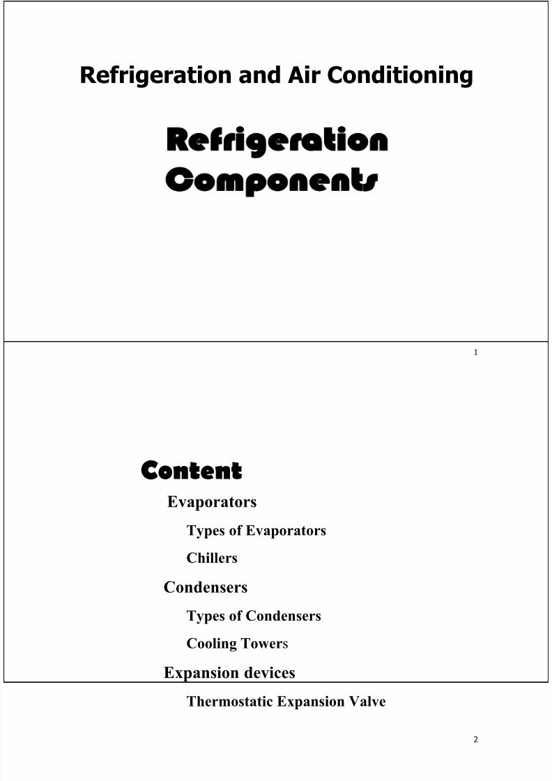
Vapor-Compression Refrigeration Components
expansiondevice
A
F condenser
p r e s s u r e
B
CE D
compressor
enthalpy
evaporator
4
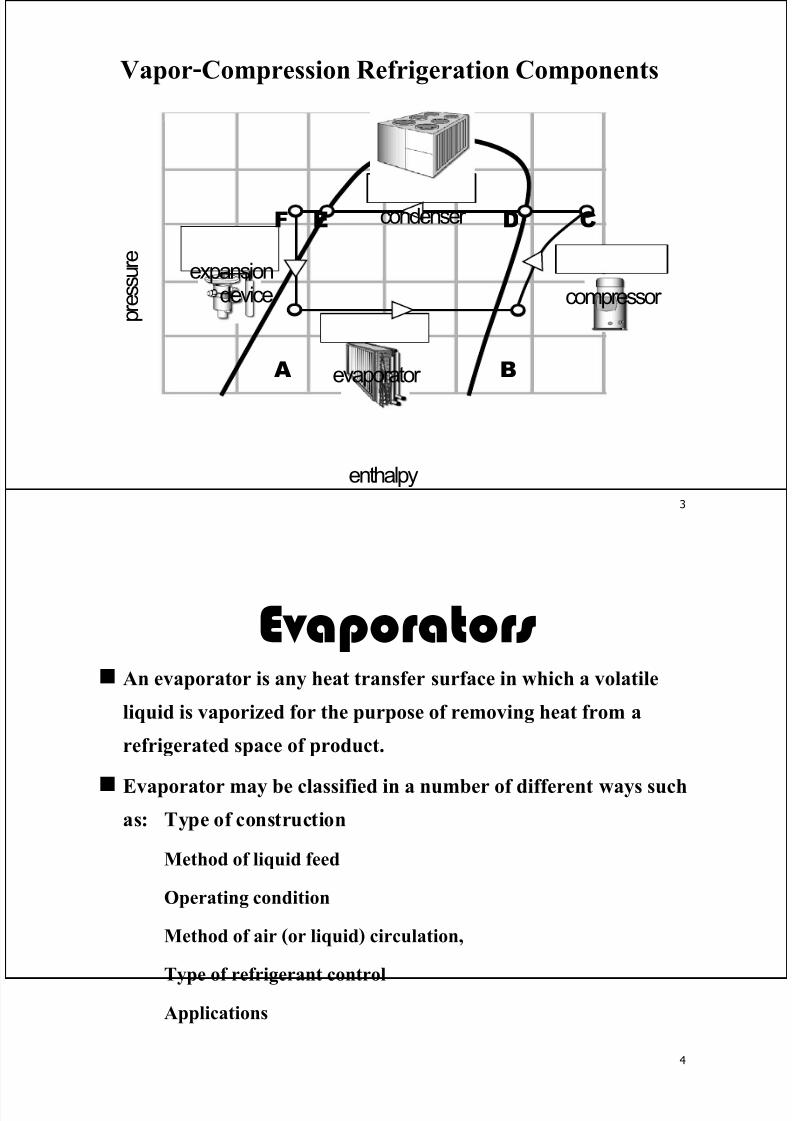
Evaporators An evaporator is any heat transfer surface in which a volatile
liquid is vaporized for the purpose of removing heat from a
refrigerated space of product.
Evaporator may be classified in a number of different ways such
as: Type of construction
Method of liquid feed
Operating condition
Method of air (or liquid) circulation,
Type of refrigerant control
Applications
7/29/2019 chiller
http://slidepdf.com/reader/full/-chiller 3/21
5
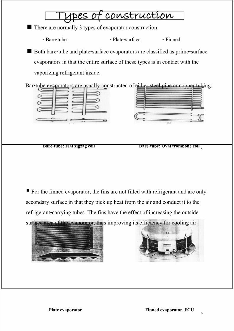
Types of construction There are normally 3 types of evaporator construction:
- Bare-tube - Plate-surface - Finned
Both bare-tube and plate-surface evaporators are classified as prime-surface
evaporators in that the entire surface of these types is in contact with the
vaporizing refrigerant inside.
Bare-tube: Flat zigzag coil Bare-tube: Oval trombone coil
Bar-tube evaporators are usually constructed of either steel pipe or copper tubing.
6Plate evaporator Finned evaporator, FCU
For the finned evaporator, the fins are not filled with refrigerant and are only
secondary surface in that they pick up heat from the air and conduct it to the
refrigerant-carrying tubes. The fins have the effect of increasing the outside
surface area of the evaporator, thus improving its efficiency for cooling air.
7/29/2019 chiller
http://slidepdf.com/reader/full/-chiller 4/21
7
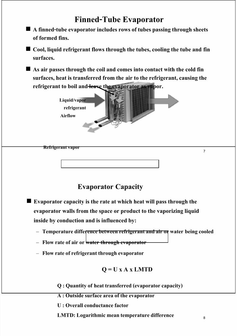
Finned-Tube Evaporator A finned-tube evaporator includes rows of tubes passing through sheets
of formed fins.
Cool, liquid refrigerant flows through the tubes, cooling the tube and fin
surfaces.
As air passes through the coil and comes into contact with the cold fin
surfaces, heat is transferred from the air to the refrigerant, causing the
refrigerant to boil and leave the evaporator as vapor.
Refrigerant vapor
Liquid/vapor
refrigerant
Airflow
8
Evaporator Capacity
Evaporator capacity is the rate at which heat will pass through the
evaporator walls from the space or product to the vaporizing liquid
inside by conduction and is influenced by:
– Temperature difference between refrigerant and air or water being cooled
– Flow rate of air or water through evaporator
– Flow rate of refrigerant through evaporator
Q = U x A x LMTD
Q : Quantity of heat transferred (evaporator capacity)
A : Outside surface area of the evaporator
U : Overall conductance factor
LMTD: Logarithmic mean temperature difference
7/29/2019 chiller
http://slidepdf.com/reader/full/-chiller 5/21
9
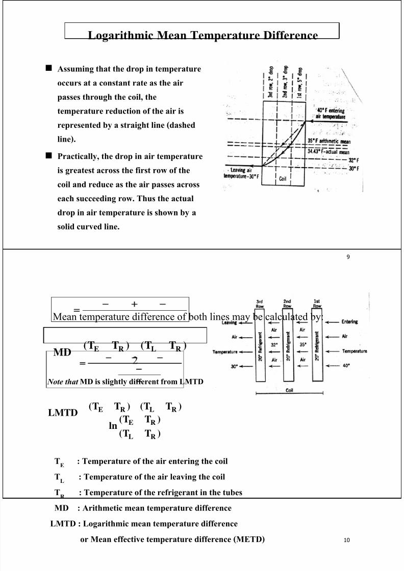
Assuming that the drop in temperature
occurs at a constant rate as the air
passes through the coil, thetemperature reduction of the air is
represented by a straight line (dashed
line).
Practically, the drop in air temperature
is greatest across the first row of the
coil and reduce as the air passes across
each succeeding row. Thus the actualdrop in air temperature is shown by a
solid curved line.
Logarithmic Mean Temperature Difference
10
Mean temperature difference of both lines may be calculated by:
2
)TT()TT(MD RLRE −
=
)TT(
)TT(ln
)TT()TT(LMTD
RL
RE
RLRE
−
−
−=
TE
: Temperature of the air entering the coil
TL
: Temperature of the air leaving the coil
TR
: Temperature of the refrigerant in the tubes
MD : Arithmetic mean temperature difference
LMTD : Logarithmic mean temperature difference
or Mean effective temperature difference (METD)
Note that MD is slightly different from LMTD
7/29/2019 chiller
http://slidepdf.com/reader/full/-chiller 6/21
11
To avoid unnecessary losses in compressor capacity and efficiency, it is
desirable to design the evaporator so that the refrigerant experiences a
minimum drop in pressure.
A certain amount of pressure drop is required, however, to flow the refrigerant
through the evaporator.
The drop in pressure must be sufficient to ensure refrigerant velocities high
enough to sweep the tube surface free of vapor bubbles.
Good design of the evaporator circuiting is required to provide the minimum
necessary pressure drop to produce sufficient refrigerant velocities.
The drop in pressure through any one evaporator circuit will generally depend
on :
The side of the tube
The length of the circuit
The circuit load (the time rate of heat flow through the tube walls of
the circuit).
Evaporator Circuiting
12
The circuit load determines the quantity of refrigerant that must pass through
the circuit per unit time.
The greater the amount of refrigerant flowing through the circuit, the greater
will be the pressure drop.
For a given tube size, the greater the load on the circuit, the shorter the circuit
must be in order to avoid excessive pressure drop.
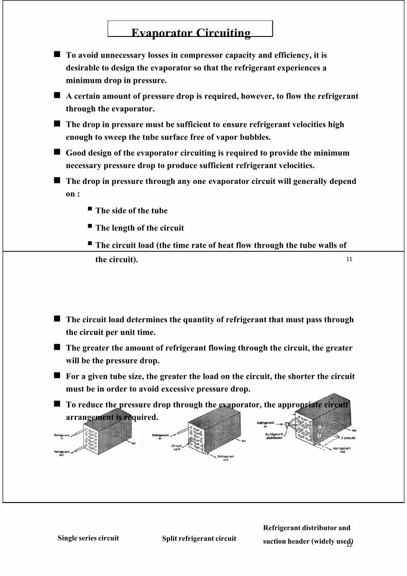
To reduce the pressure drop through the evaporator, the appropriate circuitarrangement is required.
Single series circuit Split refrigerant circuit
Refrigerant distributor and
suction header (widely used)
7/29/2019 chiller
http://slidepdf.com/reader/full/-chiller 7/21
13
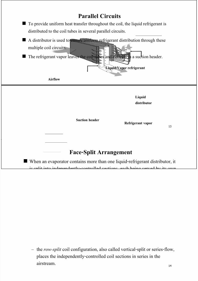
Parallel Circuits
To provide uniform heat transfer throughout the coil, the liquid refrigerant is
distributed to the coil tubes in several parallel circuits.
A distributor is used to ensure uniform refrigerant distribution through these
multiple coil circuits. The refrigerant vapor leaves the coil tubes and collects in a suction header.
Liquid/Vapor refrigerant
Refrigerant vapor
Liquiddistributor
Airflow
Suction header
14
Face-Split Arrangement
When an evaporator contains more than one liquid-refrigerant distributor, it
is split into independently-controlled sections, each being served by its own
expansion valve.
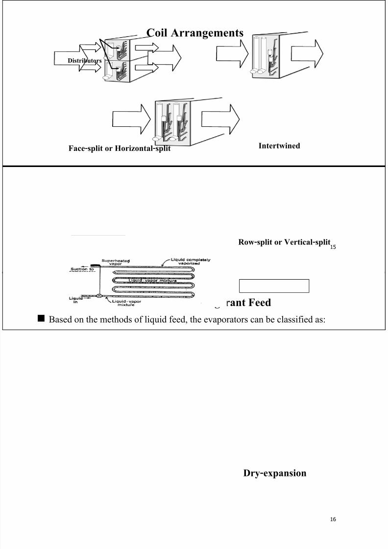
The three common arrangements for splitting finned-tube evaporator coils
include: Face-split
Intertwined
Row-split
– The face-split coil configuration, also called horizontal-split or parallel-
flow, is split into parallel sections.
– The intertwined coil configuration splits the coil sections by alternating
the tubes fed in each row between two distributors.
– the row-split coil configuration, also called vertical-split or series-flow,
places the independently-controlled coil sections in series in the
airstream.
7/29/2019 chiller
http://slidepdf.com/reader/full/-chiller 8/21
15
Coil Arrangements
Distributors
Face-split or Horizontal-split
Row-split or Vertical-split
Intertwined
16
Methods of Refrigerant Feed
Based on the methods of liquid feed, the evaporators can be classified as:
- Dry-expansion - Liquid overfeed - Flooded
With the dry-expansion evaporator, the amount of liquid refrigerant fed into theevaporator is limited to that which can be completely vaporized by the time it
reaches the end of the evaporator.
Dry-expansion
7/29/2019 chiller
http://slidepdf.com/reader/full/-chiller 9/21
17
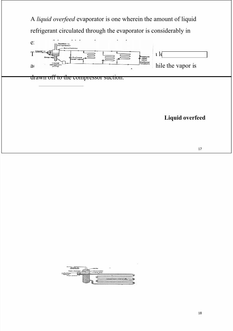
A liquid overfeed evaporator is one wherein the amount of liquid
refrigerant circulated through the evaporator is considerably in
excess of that which can be vaporized.
The excess liquid is separated from the vapor in a low-pressure
accumulator and recirculated to the evaporator while the vapor is
drawn off to the compressor suction.
Liquid overfeed
18
The full-flooded method is operated completely filled with liquid refrigerant,
thus, proving the greatest amount of interior wetted tube surface and the
highest possible heat transfer rate.
– An accumulator serves as a reservoir from which the refrigerant is circulated
by gravity through the evaporator circuits.
– A low-side or high-side float control maintains the liquid level in the
accumulator.
– The vapor generated by the boiling action of the refrigerant in the tubes is
separated from the liquid in the upper part of the accumulator. Therefore, the
flash gas resulting from the reduction of pressure never enters the heat
transfer portion of the evaporator.
7/29/2019 chiller
http://slidepdf.com/reader/full/-chiller 10/21
19
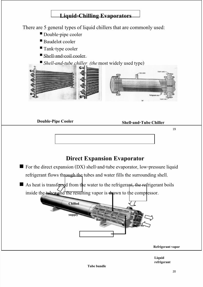
Liquid-Chilling Evaporators
There are 5 general types of liquid chillers that are commonly used:
Double-pipe cooler
Baudelot cooler
Tank-type cooler Shell-and-coil cooler
Shell-and-tube chiller (the most widely used type)
Double-Pipe Cooler Shell-and-Tube Chiller
20
Direct Expansion Evaporator
Refrigerant vapor
Liquid
refrigerant
Chilled
water
return
Chilled
water
supply
Tube bundle
Baffles
For the direct expansion (DX) shell-and-tube evaporator, low-pressure liquid
refrigerant flows through the tubes and water fills the surrounding shell.
As heat is transferred from the water to the refrigerant, the refrigerant boils
inside the tubes and the resulting vapor is drawn to the compressor.
7/29/2019 chiller
http://slidepdf.com/reader/full/-chiller 11/21
21
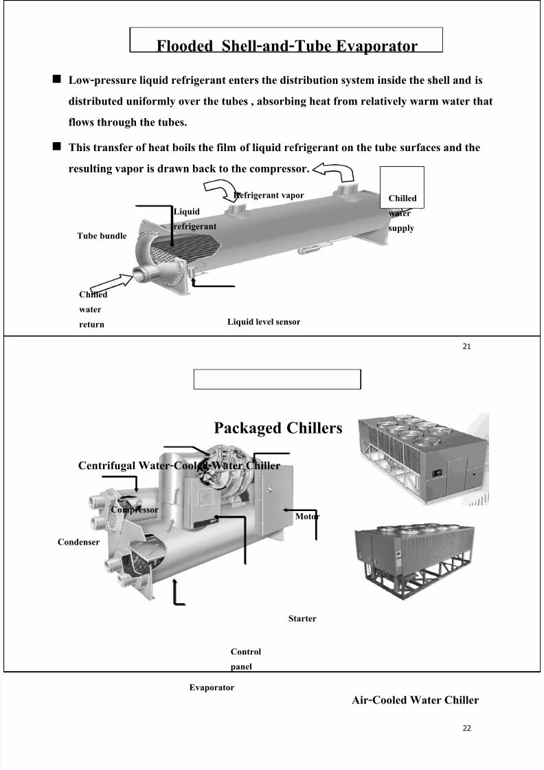
Flooded Shell-and-Tube Evaporator
Low-pressure liquid refrigerant enters the distribution system inside the shell and is
distributed uniformly over the tubes , absorbing heat from relatively warm water that
flows through the tubes.
This transfer of heat boils the film of liquid refrigerant on the tube surfaces and the
resulting vapor is drawn back to the compressor.
Chilled
water
return Liquid level sensor
Tube bundle
Refrigerant vapor
Liquid
refrigerant
Chilled
water
supply
22
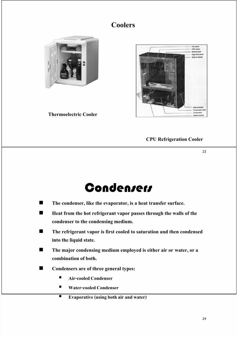
Packaged Chillers
Centrifugal Water-Cooled Water Chiller
Condenser
Compressor
Control
panel
Evaporator
Starter
Motor
Air-Cooled Water Chiller
7/29/2019 chiller
http://slidepdf.com/reader/full/-chiller 12/21
23
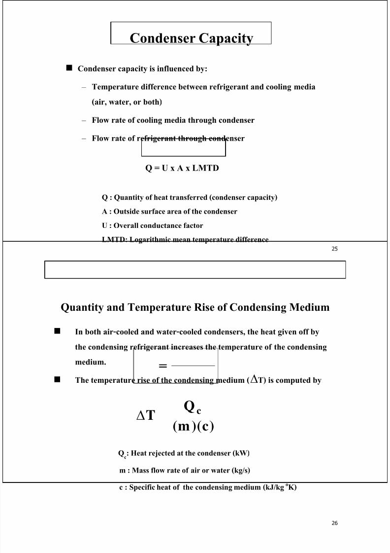
Coolers
CPU Refrigeration Cooler
Thermoelectric Cooler
24
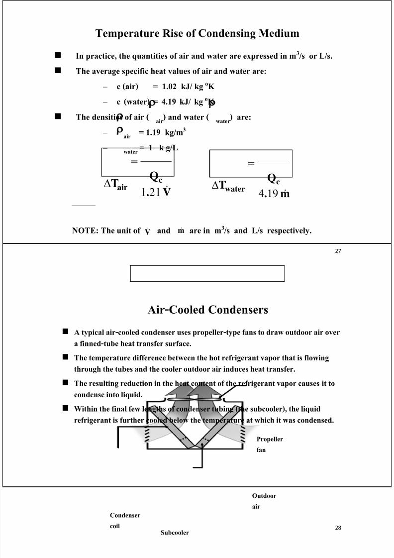
Condensers The condenser, like the evaporator, is a heat transfer surface.
Heat from the hot refrigerant vapor passes through the walls of the
condenser to the condensing medium.
The refrigerant vapor is first cooled to saturation and then condensed
into the liquid state.
The major condensing medium employed is either air or water, or a
combination of both.
Condensers are of three general types:
Air-cooled Condenser
Water-cooled Condenser
Evaporative (using both air and water)
7/29/2019 chiller
http://slidepdf.com/reader/full/-chiller 13/21
25
Condenser Capacity
Condenser capacity is influenced by:
– Temperature difference between refrigerant and cooling media
(air, water, or both)
– Flow rate of cooling media through condenser
– Flow rate of refrigerant through condenser
Q = U x A x LMTD
Q : Quantity of heat transferred (condenser capacity)
A : Outside surface area of the condenser
U : Overall conductance factor
LMTD: Logarithmic mean temperature difference
26
Quantity and Temperature Rise of Condensing Medium
In both air-cooled and water-cooled condensers, the heat given off by
the condensing refrigerant increases the temperature of the condensing
medium.
The temperature rise of the condensing medium (∆T) is computed by
Qc: Heat rejected at the condenser (kW)
m : Mass flow rate of air or water (kg/s)
c : Specific heat of the condensing medium (kJ/kg oK)
)c)(m(
QT c=Δ
7/29/2019 chiller
http://slidepdf.com/reader/full/-chiller 14/21
7/29/2019 chiller
http://slidepdf.com/reader/full/-chiller 15/21
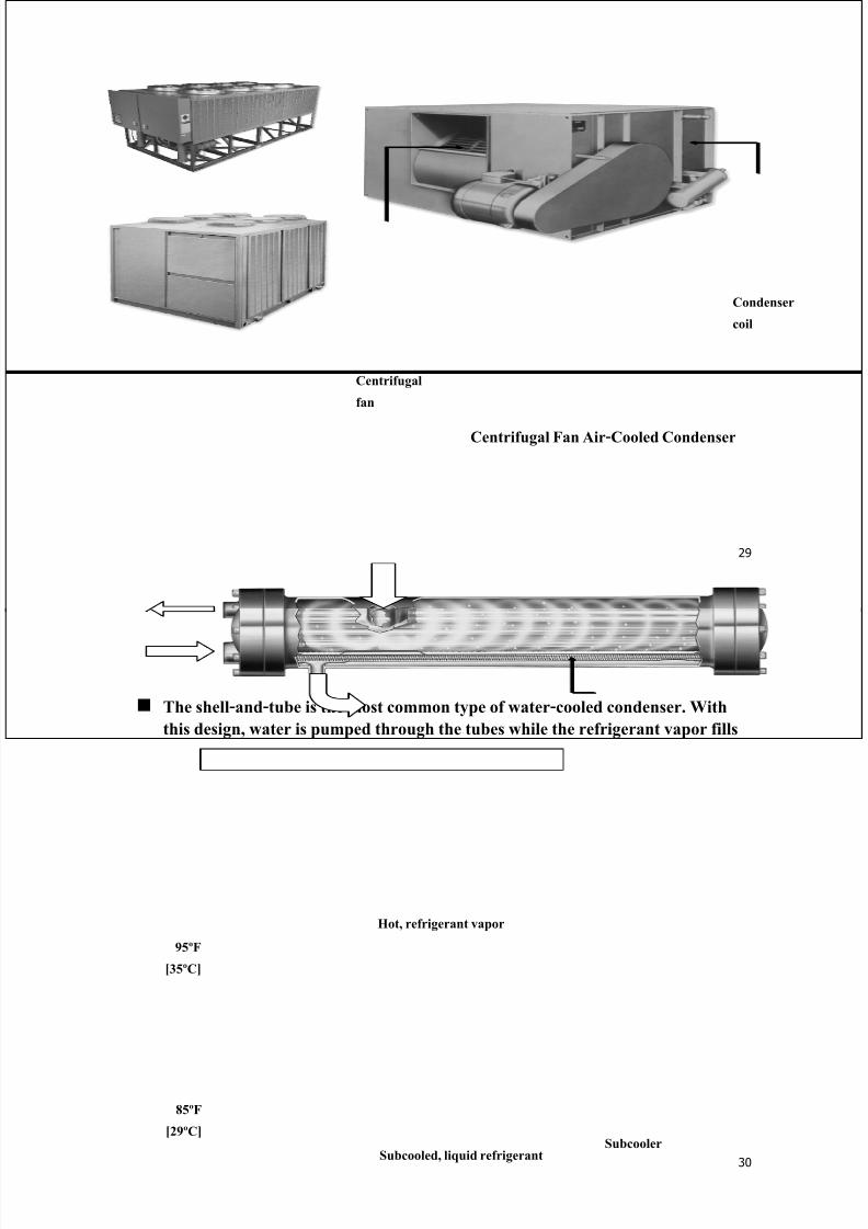
29
Centrifugal
fan
Condenser
coil
Centrifugal Fan Air-Cooled Condenser
30
Water-Cooled Condensers
The shell-and-tube is the most common type of water-cooled condenser. With
this design, water is pumped through the tubes while the refrigerant vapor fills
the shell space surrounding the tubes.
As heat is transferred from the refrigerant to the water, the refrigerant vapor
condenses on the tube surfaces.
The condensed liquid refrigerant then falls to the bottom of the shell, where it
flows through an enclosure that contains additional tubes (the subcooler).
More heat is transferred from the liquid refrigerant to the water inside these
tubes, subcooling the refrigerant.
Cooling water
Subcooled, liquid refrigerantSubcooler
Hot, refrigerant vapor
85ºF
[29ºC]
95ºF
[35ºC]
7/29/2019 chiller
http://slidepdf.com/reader/full/-chiller 16/21
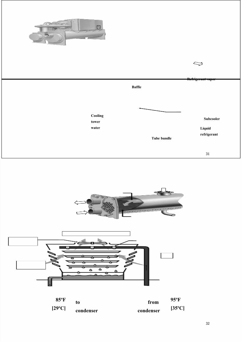
31
Subcooler
Liquid
refrigerant
Baffle
Tube bundle
Refrigerant vapor
Cooling
tower
water
32
Cooling Towers
Sprays
from
condenser
to
condenser
Sump
Propeller
fan
Outdoor
air
85ºF
[29ºC]
95ºF
[35ºC]
Filler
7/29/2019 chiller
http://slidepdf.com/reader/full/-chiller 17/21
33
A cooling tower is a device commonly used to cool condensing water.
Warm water is sprayed over fill in the cooling tower while a propeller fan
draws outdoor air upward through the fill.
The movement of air through the spray causes some of the water to
evaporate, a process that cools the remaining water. This cooled water
then falls to the tower sump to be returned to the condenser.
The evaporation process uses up water to dissipate heat. As the water
evaporates, the dissolved minerals and water treatment chemicals become
concentrated in the sump.
To prevent this solution from becoming concentrated and possibly
corrosive, water is periodically bled from the sump and an equal amount
of fresh water is added.
34
The effectiveness of the cooling tower depends upon:
The web bulb temperature of the entering air
The amount of exposed water surface and the length of time of
exposure
The velocity of the air passing through the tower
The direction of the air flow with relation to the exposed water surface
- Parallel - Transverse - Counter
The temperature of the water leaving the tower will usually be 7-10 oC
above the web bulb temperature of the entering air.
The difference between the temperature of the water leaving the tower
and the wet bulb temperature of the entering air is called the Approach
of the tower
The temperature difference between the entering and leaving water is
called the Range of the tower .
7/29/2019 chiller
http://slidepdf.com/reader/full/-chiller 18/21
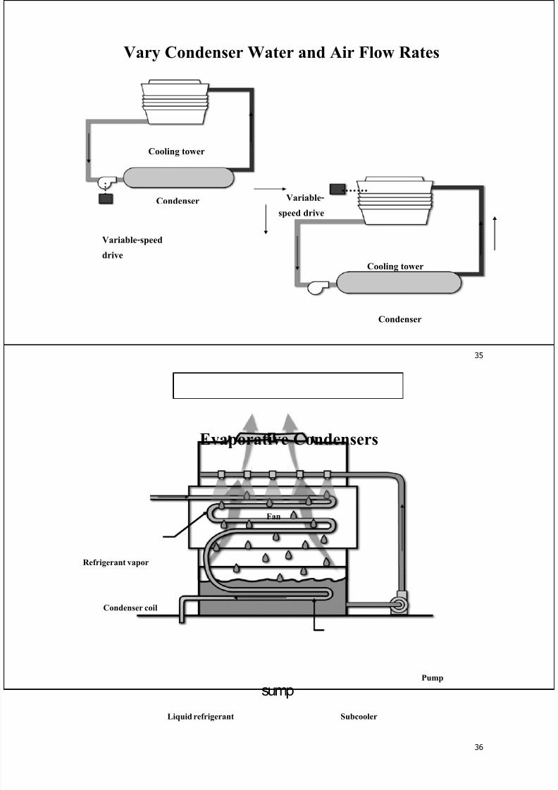
35
Vary Condenser Water and Air Flow Rates
Cooling tower
Condenser
Variable-speed
drive
Cooling tower
Condenser
Variable-
speed drive
36
Evaporative Condensers
sump
Pump
Condenser coil
Refrigerant vapor
Subcooler
Fan
Liquid refrigerant
7/29/2019 chiller
http://slidepdf.com/reader/full/-chiller 19/21
37
A modification of the air-cooled condenser is the evaporative condenser.
Within this device, the refrigerant flows through tubes and air is drawn or
blown over the tubes by a fan. And water is sprayed on the tube surfaces.
As the air passes over the coil, it causes a small portion of the water to
evaporate. This evaporation process absorbs heat from the coil, causing the
refrigerant vapor within the tubes to condense. The remaining water then
falls to the sump to be recirculated and used again.
Subcooling of the refrigerant can be accomplished by piping the condensed
liquid back through another few rows of coil tubing, located either in the
condenser air stream or in the water sump, where additional heat transfer
reduces the temperature of the liquid refrigerant.
38
Expansion Devices
An expansion device is used to maintain a pressure difference between
the high-pressure (condenser) and low-pressure (evaporator) sides of the
system established by the compressor.
This pressure difference allows the evaporator temperature to be low
enough to absorb heat from the air or water to be cooled, while also
allowing the refrigerant to be at a high enough temperature in the
condenser to reject heat to air or water at normally available
temperatures.
There are several types of expansion devices, including expansion valves
(thermostatic or electronic), capillary tubes, and orifices.
Thermostatic expansion valves (TXVs) are commonly used and perform
essentially the same function as other expansion devices.
7/29/2019 chiller
http://slidepdf.com/reader/full/-chiller 20/21
39
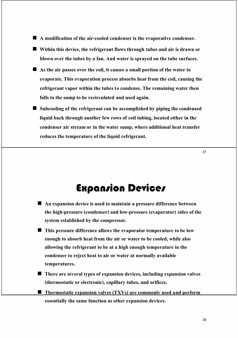
Thermostatic Expansion Valve (TXV)
In addition to maintaining a pressure difference, the thermostatic expansion
valve controls the quantity of liquid refrigerant entering the evaporator.
It ensures that the refrigerant will be completely vaporized within the
evaporator (A) and maintains the proper amount of superheat in the system.
thermostatic
expansion valve
(TXV)
liquid/vapor
mixture
refrigerant
vapor
evaporator
A
liquid
refrigerant
40
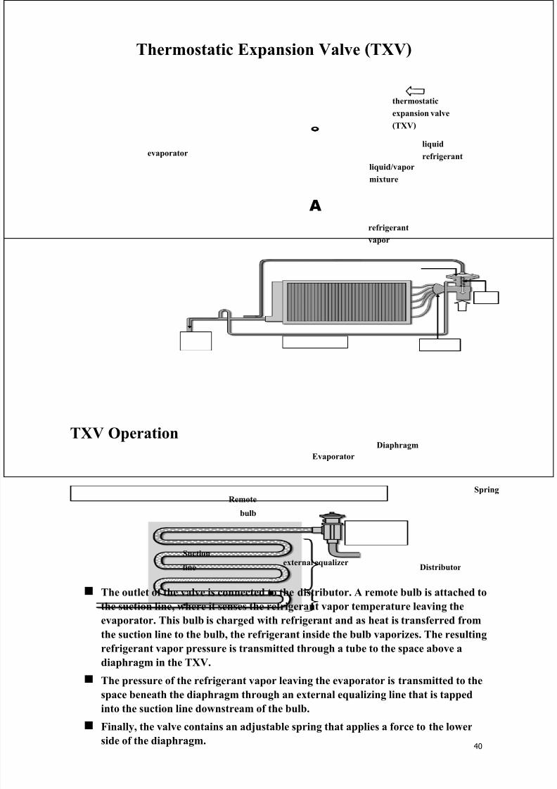
TXV Operation
external equalizer
Remote
bulb
Evaporator
Spring
Suction
line Distributor
Diaphragm
The outlet of the valve is connected to the distributor. A remote bulb is attached to
the suction line, where it senses the refrigerant vapor temperature leaving the
evaporator. This bulb is charged with refrigerant and as heat is transferred from
the suction line to the bulb, the refrigerant inside the bulb vaporizes. The resulting
refrigerant vapor pressure is transmitted through a tube to the space above a
diaphragm in the TXV.
The pressure of the refrigerant vapor leaving the evaporator is transmitted to the
space beneath the diaphragm through an external equalizing line that is tapped
into the suction line downstream of the bulb.
Finally, the valve contains an adjustable spring that applies a force to the lower
side of the diaphragm.
7/29/2019 chiller
http://slidepdf.com/reader/full/-chiller 21/21
41
valve pinsuction
line
spring94ºC
0.54 MPa
0.67 MPa
0.54 MPa 0.13 MPa
valve diaphragm
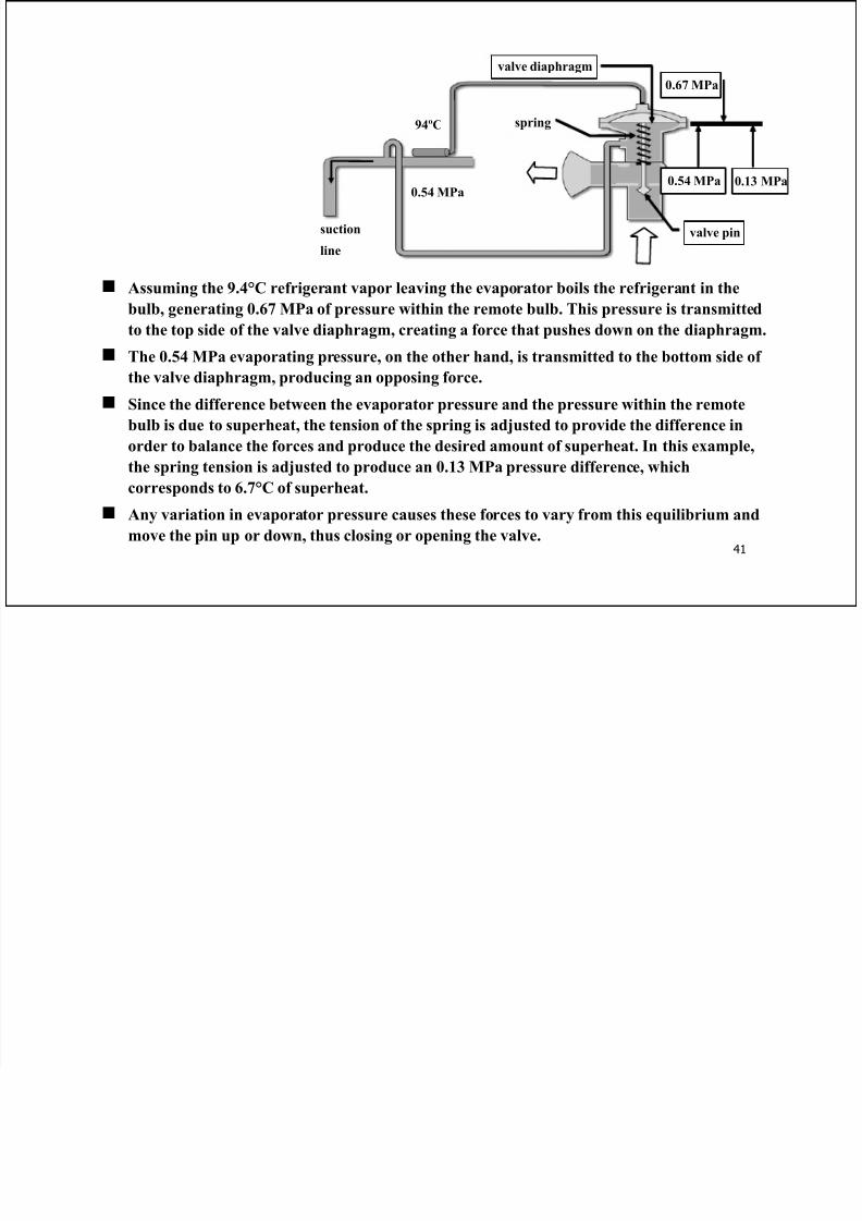
Assuming the 9.4°C refrigerant vapor leaving the evaporator boils the refrigerant in the
bulb, generating 0.67 MPa of pressure within the remote bulb. This pressure is transmitted
to the top side of the valve diaphragm, creating a force that pushes down on the diaphragm.
The 0.54 MPa evaporating pressure, on the other hand, is transmitted to the bottom side of
the valve diaphragm, producing an opposing force.
Since the difference between the evaporator pressure and the pressure within the remote
bulb is due to superheat, the tension of the spring is adjusted to provide the difference inorder to balance the forces and produce the desired amount of superheat. In this example,
the spring tension is adjusted to produce an 0.13 MPa pressure difference, which
corresponds to 6.7°C of superheat.
Any variation in evaporator pressure causes these forces to vary from this equilibrium and
move the pin up or down, thus closing or opening the valve.