Embed Size (px)
Citation preview

CAT.No. 撹 M-35(106)
Mixing Control Technology
Series
Impeller Series
高性能インペラ
High Performance Impellers: Super-Mix Series
®
シリーズ
サタケ インペラシリーズ

1
撹拌の役割
朝の一杯のコーヒーを飲む時、砂糖を入れ、スプーンでカッ
プの中を、かき混ぜることも撹拌であり、また、記録メディアの
品質を維持するための磁性体の反応分散操作も撹拌の一つな
のです。
コーヒーの例で、コーヒーの中の砂糖をかき混ぜなかったら
どうでしょう。化学的にはコーヒーの温度における飽和度に達
するまで砂糖は溶け続けるはずです。しかし、底に沈んだ砂糖
は、その表面を溶かしただけで回りのコーヒーは飽和度に達し
てしまいます。あとはコーヒー液中の拡散現象にまかせるしか
なく、砂糖が溶解して濃度が一様になるには、膨大な時間がか
かるでしょう。この意味からすれば“撹拌”とは時間短縮のため
の操作といえます。
磁性体の反応槽の例を見ますと、化学反応操作と言うもの
は、その高圧、高温に代表される人為的環境操作もそうですが、
それらを反応槽内で均一に保とうとする高撹拌エネルギーが
重要な働きをしています。この場合、“撹拌”は時間を超越した
新物質製造操作といえるでしょう。
インペラは回転エネルギーを運動エネルギーに変換する、撹拌
機にとって最も重要な部分です
インペラは撹拌装置の中で最も重要な部分です。モータから
発生された回転エネルギーはシャフトを通してインペラに伝
わり運動エネルギーに変換されます。
この時、流体運動とともに圧力剪断が発生し、その割合と吐
出流方向により作られるフローパターンによって、インペラの
特性は軸流型と輻流型に分類されます。
代表的な各種インペラ別分類を7ページに示します。またイ
Role of mixing
The technology of mixing is something we’re all
familiar with — stirring sugar into your coffee is a
mixing operation. In the same way, the reaction
dispersion of magnetic material to maintain original the
quality of the recording medium also represents a type
of mixing.
What will happen if you do not stir your coffee?
Chemically speaking, sugar should keep dissolving
until coffee reaches saturation at the specific water
temperature. But as we all know from experience,
sugar stays at the bottom and gets partially dissolved
but the coffee quickly reaches saturation. Without
stirring, it will take very a long time before sugar
diffuses completely and uniformly by the diffusion
phenomenon of the liquid and the coffee is finally
ready for drinking. In this sense,
“mixing” may be defined as a
process of reducing the diffusion
time.
Take the reaction tank of magnetic
material for example, a chemical
reaction requires artificial adjustment
of environmental factors, such as
pressure and temperature. Equally
important is high mixing energy
to keep all these factors uniform
ンペラ重量は、シャフト長さとともに危険回転数の値に大きな
影響を及ぼします。したがって、シャフトをリジット(剛性軸)と
するために、できるだけ軽くしなければなりません。その設計に
は流体反力を考慮した、機械的強度の検討が重要になります。
高性能インペラ スーパーミックスシリーズ
本カタログでは、撹拌目的に最適のインペラを選定いただ
くためのインペラについての基本的な情報と、サタケが自信を
もってお届けする高性能インペラ、スーパーミックスシリーズ
の各インペラをご紹介しています。
より高い信頼性と撹拌効果を追求して撹拌技術は進 歩しつづけます。Evolving toward Better, More Reliable Mixing Tech nology

2
The weight of the impeller has direct impact on the
critical speed of rotation, as well as the shaft length,
and must be minimized in relation to the rigid shaft.
The impeller design requires careful study of the
mechanical strength, taking the reaction force of fluids
into consideration.
High Performance Impellers — Super-Mix Series
This catalog contains basic information about
impellers, and introduces Satake’s impellers in the High
Performance Super-Mix Series. It is designed to guide
you through the selection of impellers to help you meet
your specific needs.
より高い信頼性と撹拌効果を追求して撹拌技術は進 歩しつづけます。Evolving toward Better, More Reliable Mixing Tech nology
減速機構Reduction gear
メカニカルシール簡易交換機構Mechanical seal easy-exchange mechanism
シャフト支持装置(フレーム)Shaft support (frame)
軸封装置Shaft seal
ドライブシャフトDriving shaft
フランジカップリングFlange coupling
ミキシングシャフトMixing shaft
インペラImpeller
フートベアリング(槽底軸受)Foot bearing (at the tank bottom)
安定装置 (スタビライザーリング)Stabilizer ring
モータMotor
within the reaction tank. In this sense, “mixing” may be
defined as a process of producing a new substance.
The impeller is a critical element of the mixer that
converts rotational energy into kinetic energy
The impeller is the most important element of the
mixer. Rotational energy, generated by the motor, is
transmitted from the shaft to the impeller as kinetic
energy. The fluidic motion around the impeller is
associated with pressure shear, and the impellers are
grouped into two characteristic types (axial flow, radial
flow) according to the ratio of pressure shear and the
flow pattern, determined by the direction of discharge
flow. (Typical types of impellers are shown on P7.)
ミキシングシャフトMixing shaft
ベアリングケースBearing case
フートサポートFoot support
スリーブSleeve
フートベアリングFoot bearing
標準Standard

3
インペラの基礎知識
インペラの選定方法
インペラとは、一般の撹拌操作で用
いられる回転式撹拌翼の総称です。撹拌
操作そのものは、多くの産業分野で使用
されていますが、系統だった研究開発が
なされるようになったのは近年のこと
です。その形状やインペラ径は、撹拌目
的、操作条件を前提に回転数と同時に
検討され、決定されるものです。それは、
撹拌槽内の流動状態が撹拌レイノルズ
数(NRe)に影響されるためであり、レイ
ノルズ数自体に決定すべき、さまざまな
ファクターを含むためです。
レイノルズ数とは、流体の流動状態を
知るための指標となり、一般に流体の密
度ρ[kg/m3]、粘度μ[Pa・s]と、その系
の代表長さℓ[m]、代表速度u[m/sec]に
より次式で定義されています。
撹拌の場合には、系の代表長さをイ
ンペラ径d[m]、代表速度をインペラ周
速n・d[m/sec]を用いて次式で表しま
す。
Re=ρ·u·ℓ
μ[—]
撹拌レイノルズ数と流動状態Reynolds number of mixing and fluidic conditions
Basic Knowledge about Imp ellers
撹拌レイノルズ数NReとインペラ形
状がわかれば槽内の大まかな流動状態
を知ることができます。これらのことに
より、単に高粘度・低粘度と選定基準に
するのではなく、インペラ回転数、イン
ペラ径、槽の寸法等の諸条件を踏まえて
総合的に判断することが重要です。
撹拌翼形状と撹拌作用
撹拌装置の構成要素の中で最も重要
な部分を占める撹拌翼は、駆動源から回
転運動の機械的エネルギーを与えられ
ることにより2つの大きな仕事をしてい
ます。
(1)撹拌槽内の液全体を流動させる液
循環作用と、(2)局所的な混合を達成さ
せる速度勾配による剪断作用です。プロ
ペラ翼は、船舶の推進機や航空機の翼か
ら転用され研究したもので、羽根の背面
に生ずる流れの剥離を極力防止させ、効
率良く吐出流を集中させて軸流とさせ
ています。
一方、フラットパドル翼やフラット
タービン翼は羽根板の縁に生ずる剥離
渦や背面の剥離流による圧力や剪断の
割合の大きい撹拌翼です。
但し、最近の研究では流場を利用した
10 102
102
10
1
0.1
103
103 104 105 106
(a)層流 局部的流動
(b)層流 上下循環発生
(c)過渡状態 (d1)邪魔板付き 上下循環が主
(d2)邪魔板なし 旋回流が主
(a・b)リボン翼の場合 強制混合形成
停滞部
層流部
乱流部
(a) Laminar flow (b) Laminar flow
(c) Transient state(d1) Baffled (d2) Non-baffled
(a, b) Ribbon blades
Stagnation zone
Laminar zone
Turbulence zone
Nqd=qd n ·d³
NTM=TM·n
(a)
(b)
(c)(d)
NRe=ρ·n·d²
NTM-NRe
Np-NRe
(擬塑性液)
Np-NRe
Nqd-NRe
(パドル形)(Paddle type)
(タービン形)(Turbine type)
(吐出特性)Discharge characteristics
Nqd-NRe曲線Nqd-NRe curve
Np-NRe曲線 Np-NRe curve
動力特性 Drive characteristics
NTM-NRe曲線 NTM-NRe curve
混合特性 Mixing characteristics
邪魔板つき Baffled邪魔板なし Non-baffled
Np=
P·gc
·n³ ·d⁵
ρ
μ
Local fluidization Vertical circulation Forced mixing
Mainly vertical circulation
Mainly swirls
(Quasi-plasticliquid) NRe
ここではインペラについて理解していただくため、またインペラ選定の参考としていただくため、インペラの基礎知識、選定の基本、吐出性能別分類、各インペラの形状・フローパターンについて記載しています。詳細につきましては当社までお問い合わせください。
The following pages contain
impor tan t re fe rences fo r
u n d e r s t a n d i n g i m p e l l e r s
including basic knowledge
about impel lers and their
selection, classification by
discharge performance, their
shapes and flow patterns.
Please contact Satake for
additional information.
NRe= ρ·n·d2
μ[—]
4
Methods of selecting impellers
An impeller is a generic term for
rotational mixing blades. Mixing itself
is a common operation in many
industries, but systematic R&D efforts
about mixing started only a few years
ago. The impeller shape and diameter
are studied carefully, along with the rate
of rotation, according to the purpose
of mixing and working conditions.
This profess is important as the fluidic
condition in the mixing tank is affected
by Reynolds number which, in turn, is
determined by various factors.
The Reynolds number is an index
that represents the fluidic condition of
a fluid. It is usually expressed by the
following equation taking density ρ[kg/
m3] and viscosity μ[Pa.s] of the fluid,
and the typical length ℓ[m] and typical
speed u[m/sec] of the system into
consideration:
With regard to mixing, the Reynolds
number is expressed as shown below
using the impeller’s diameter d[m] as
the system’s typical length and the
impeller’s circumferential speed n(1/
sec).d[m] as the typical speed:
If the Reynolds number of mixing NRe
and the impeller shape are known, you
should be able to tell rough conditions
of the fluid in the tank. This is to say
the density (low or high) is not the only
criteria of selection. Impellers must be
selected comprehensively taking the
impeller speed and diameter, the tank
dimensions and various other factors
into account.
高剪断の低動力型タービンも開発され
てきており、流動状態と撹拌目的に合っ
た作用を的確に与えることが重要です。
下に示す図は、インペラ形状を選定す
るときの一般的な目安にはなりますが、
撹拌目的や撹拌液の物性などによって
異なりますので、絶対的なものではあり
ません。
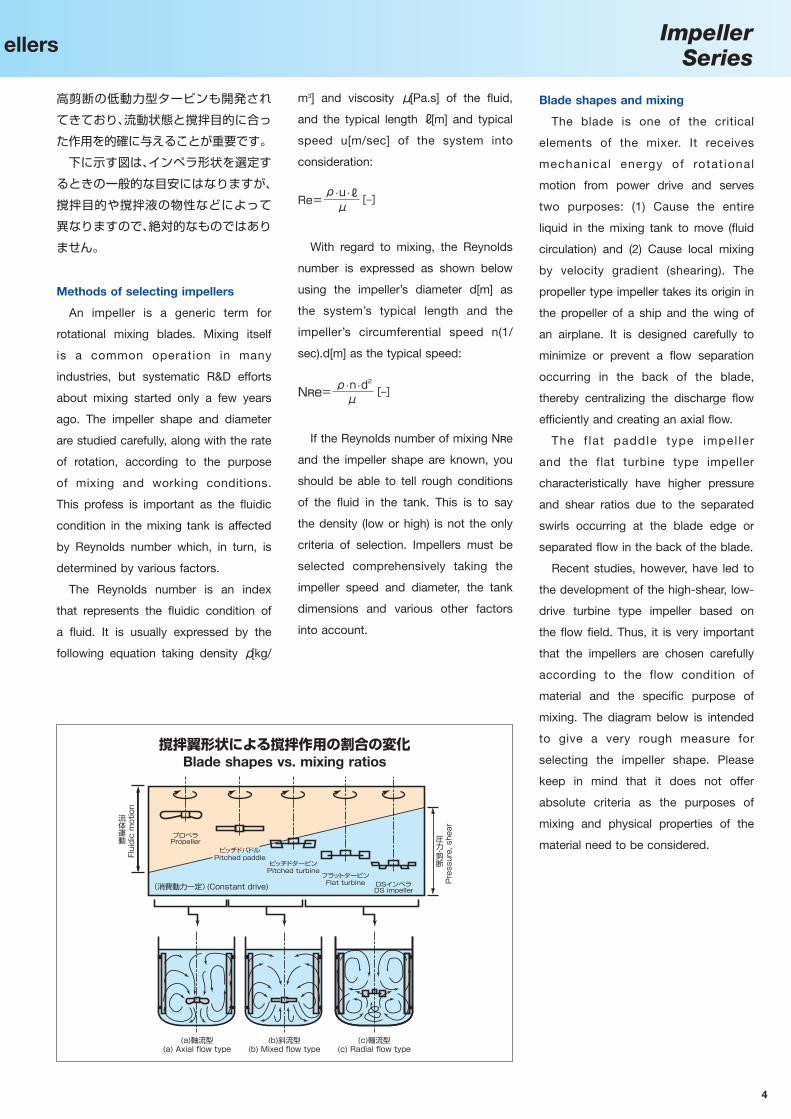
Blade shapes and mixing
The blade is one of the critical
elements of the mixer. It receives
mechanical energy of rotat ional
motion from power drive and serves
two purposes: (1) Cause the entire
liquid in the mixing tank to move (fluid
circulation) and (2) Cause local mixing
by velocity gradient (shearing). The
propeller type impeller takes its origin in
the propeller of a ship and the wing of
an airplane. It is designed carefully to
minimize or prevent a flow separation
occurring in the back of the blade,
thereby centralizing the discharge flow
efficiently and creating an axial flow.
The f lat paddle type impel ler
and the flat turbine type impeller
characteristically have higher pressure
and shear ratios due to the separated
swirls occurring at the blade edge or
separated flow in the back of the blade.
Recent studies, however, have led to
the development of the high-shear, low-
drive turbine type impeller based on
the flow field. Thus, it is very important
that the impellers are chosen carefully
according to the flow condition of
material and the specific purpose of
mixing. The diagram below is intended
to give a very rough measure for
selecting the impeller shape. Please
keep in mind that it does not offer
absolute criteria as the purposes of
mixing and physical properties of the
material need to be considered.
Basic Knowledge about Imp ellers
撹拌翼形状による撹拌作用の割合の変化Blade shapes vs. mixing ratios
(a)軸流型 (b)斜流型 (c)輻流型
プロペラ
ピッチドパドル
ピッチドタービン
フラットタービンDSインペラ(消費動力一定)
流体運動
(a) Axial flow type (b) Mixed flow type (c) Radial flow type
Propeller
Pitched paddle
Pitched turbine
Flat turbineDS impeller(Constant drive)
圧力・剪断
Fluidic motion
Pressure, shear
ImpellerSeries
Re=ρ·u·ℓ
μ[—]
NRe= ρ·n·d2
μ[—]

5
インペラ選定の基本
1.可溶性液体(単一液体含む)の場合
吐出循環性能のよいプロペラ翼(各
種)やピッチドパドル翼を使用し、極め
て低いPv値(単位体積当りの撹拌動力)
で撹拌します。比較的大容量の撹拌(約
10m3)には大型広幅翼やパドル系の翼
を用い低回転にて撹拌します。
最近では、プロペラ翼を高吐出型に改
良したHR100、HR700型翼や同じく、
ピッチドパドル翼を改良したHR320、
HS400により、さらに省エネルギーで
目的を達成しています。
2.非可溶性液体の場合
剪断性能と吐出循環性能をかね備え
た、多翼タービン(DSインペラ)、ファン
タービン翼、ピッチドタービン翼、ピッ
チドパドル翼などを用います。
翼 径 の 槽 径 に 対 す る 割 合 はd/D=
0.15〜0.4程度にしています。また、撹
拌翼の取付位置は界面に設置するのが
望ましいのですが、液の混合比が1対2
以上ある場合、またはZ/Dが1.2以上あ
るときは多段翼とします。非可溶性液体
の場合は、比重差、混合比、槽の形状、及
びノンバッフル偏心・バッフルの条件な
どを十分検討しなければなりません。
(固体粒子の溶解、流動比、懸濁、分散、
解膠、晶析などが撹拌目的となる)
1.固体粒子の溶解の場合
固体粒子の溶けやすいものは、プロペ
ラ翼を用い低いPv値で撹拌します。槽の
容量が大きい(約10m3以上)場合には、
パドル系の翼を使用し、低回転にて行い
ます。また、溶けにくい粒子には、剪断作
用の強いインペラと吐出循環性能のよ
いインペラの組合せを比較的高回転で
撹拌するのもよいでしょう。
バッフルは固体粒子が浮きやすいも
のはバッフルを液面の半分くらいにし、
多少ボルテックス渦を作って粒子を強
制的に巻き込んだ方がよいでしょう。
固体の溶解により、粘度の上昇があ
り高粘性液となる場合は、広範囲の粘性
液に対応できる広幅大型翼のMR203、
MR205型翼が力を発揮します。
2.粒子の流動化及び懸濁の場合
上記同様、小容量(約10m3以下)の撹
拌及び粒子濃度の少ないもの(対象物に
より難易度は大いに異なる)は、プロペ
ラ翼、大容量(約10m3以上)及び粒子濃
度が多い場合には、ピッチドパドル翼な
どが一般的でしたが、粒子の流動化に
対しては低動力にて優れた吐出特性を
有するHR800型翼が適しています。ま
た、槽内全域での分散均一化及び槽底部
インペラ代表形状と各部の名称Typical impeller shapes and names of components
1.スパージャーリング方式の場合
気体分散用には、剪断性能に優れた円
板付きフラットタービン翼が最も多く
用いられています。しかし、吸収速度が
速い気体、または気体の供給量が少ない
ときは、プロペラ翼やパドル翼を用いて
目的を達成していることもあります。
製造用装置のほとんどは、2段以上の
組み合わせ翼を備えています。下段の分
散用にはタービン翼を用い、循環及び気
体滞留促進用に高吐出プロペラ翼(軸流
翼)を中段、または上段に取り付けます。
傾斜タービン翼(ピッチドタービン
翼)を使用した場合は、斜流型の流れが
発生するため、固形分を含む気−液接触
装置に効果を発揮します。液−液撹拌で
は円板上下の液の対流を図るため、円板
に穴を開けるが、気体分散では穴より気
体のショートパスを防ぐために設ける
ことはしません。また、良く用いられる
コーンケーブタービンの利点は、ガス吹
き込み無し時の動力(Po)とガス吹き込
み時の動力(Pg)との比Pg/Poがあまり
小さくならないため、結果的に撹拌機に
使用するモータ動力を小さくできるの
が特徴ですが、最近では通気動力特性と
ガス吸収性能を両立した新型タービン
HS100系翼が開発されています。
2.表面曝気方式の場合
この気−液接触の方式は、水処理関係
の表面曝気槽に用いられます。効率の良
い翼(プロペラ型、タービン型、コーン型
など)が開発されていますが、サタケは曝
気槽の撹拌効果も考慮して、高揚程型表
面曝気翼SA100、SA200型翼を開発、
実用化しています。
これら表面曝気専用に開発された
スーパーミックス翼は、高液深にも対応
できるように工夫されています。
Basics of Impeller Selection
A. 液−液系 B. 固−液系
C. 気−液系
よりスラリー液を均一に排出したい場
合は、槽底部にHS600系翼を用いると
均一な撹拌と均一な排出を同時に実現
できます。
インペラボスImpeller boss
ディスクDisk
ブレードBlade
インペラボスImpeller boss
ブレードBlade
インペラ径Impeller diameterブレード幅Blade width
ディスクDisk
ブレード高さBlade height
インペラボスImpeller boss
タービン型Turbine type
プロペラ型Propeller type
インペラボスImpeller boss
インペラ径Impeller diameter
ブレード角度Blade angleブレード角度Blade angle
Blade cross section
カンバー比Camber ratio
L : Length
= HL
翼断面
L : 長さ
H : 矢高
H : Camber
HR700

ImpellerSeries
6
1. Soluble liquids (including simple liquid)
Propeller impellers (of various
designs) or pitched paddle impellers of
high discharge circulation performance
are used at an extremely low Pv value
(mixing drive force per unit volume).
Impellers with large and wide blades or
paddles may be used at low speed of
revolution for relatively large volumes
(approx. 10m3).
Recently, mixing needs for this type
of liquid are met in a more energy-
saving manner by propellers of higher
discharge type (HR100 impeller, HR700
impeller) or improved pitched paddle
type (HR320 impeller, HS400 impeller).
2. Non-soluble liquids
Multi-bladed turbine impeller (DS
impeller), fan-turbine impeller, pitched
turbine impeller, pitched paddle impeller
are usually preferred for high shearing
and discharge circulation performances.
The ratio of the blade diameter to the
tank diameter (d/D) is between 0.15 and
0.4. The impeller height should preferably
be near the interface. For liquid mixing
ratio of 1:2 or more, or when Z/D is
1.2 or greater, a multi-stage blade type
will give a better result. Specific gravity
differences, mixing ratios, tank shapes,
non-baffle eccentricity, baffle conditions
and other factors must be taken into full
consideration.
1. Sparging
Flat turbine impeller with disks are
most often used for gas dispersion
because of their outstanding shearing
performance. Impellers with propellers
or paddles are also used with gases of
fast absorption speed or when the gas
supply is small.
(Solid particle dissolution, specific
fluidization, suspension, dispersion,
colloidal suspension, crystallization, etc)
1. Solid particles dissolution
Propeller impellers are used at a low
Pv value for soluble solid particles.
Paddle type impellers may be used
A. Liquid mixing
B. Solid-liquid mixing C. Gas-liquid mixing
Manufacturing equipment is normally
designed for combination of two or
more stages. Turbine impellers are
often used for dispersion at the bottom
stage and the high discharge propeller
impellers (axial flow blades) in the
middle or top stage for promoting
circulation and gas stagnation. Inclined
turbine impellers (pitched turbine
impellers) generate mixed flows and
are often preferred for ideal contact
between gas and liquid containing
solids. For liquid mixing, holes are
often provided in the disk to promote
convection between over and under the
disk. For gas dispersion, however, such
holes are not used to eliminate short
passing of gas. Cone cave turbines are
often used because of the relatively
large differential ratio Pg/Po between
drive power without gas introduction (Po)
and drive power with gas introduction
(Pg). This means the mixer requires only
a small motor drive power. The turbine
type impeller HS100 from recent efforts
is designed to meet conflicting needs
of aeration drive characteristics and gas
absorption performance.
2. Surface aeration
This type of gas and liquid contact
mixing is found in surface aeration
tanks in water treatment plants. Various
products of high efficiencies (propeller,
turbine, cone, and other types)
have been developed. Satake have
developed high lift type surface aeration
impellers (SA100 impeller, SA200
impeller) in consideration of mixing
effects in the aeration tank.
The “super-mix” impellers, developed
exclusively for this type of surface
aeration, are designed to allow for large
liquid depths.
at low speed of revolution in case of
large tank volumes (over 10m3). Non-
soluble particle may be mixed by using
a combination of an impeller of high
shearing performance and an impeller of
high discharge circulation performance
at a relatively high speed of revolution.
For solid particles that tend to float
to the surface, the baffle should be
positioned at about half the liquid
surface to create vortexes and introduce
particles into swirls by force.
Dissolution of solids accompanies
an increase in viscosity. In this case,
Impellers with large and wide blades
(MR203 impeller, MR205 impeller) will
give a better result as they are designed
for a broader range of viscous liquids.
2. Particle fluidization and suspension
Convent ional ly, impel lers with
propellers are used with small-volume
mixing (up to 10m3) or liquids of low
particle density, and pitched paddle
impellers with large-volume mixing (over
10m3) or liquids of high particle density.
HR800 impeller of high discharge
characteristics at low drive force is a
better choice when particle fluidization
is critical. Similarly, HS600 type impeller
may be used at the tank bottom for
uniform mixing and uniform discharge at
the same time when uniform dispersion
in the tank and uniform discharge of
slurry from the bottom is critical.

7
各種インペラ別分類Classification of Impellers
スー
パー
ミッ
クス
HR
70
0形
Sup
er-M
ix H
R70
0
AF1
00
イン
ペラ
一体
鋳造
形A
F100
Impe
ller
Inte
gral
type
スー
パー
ミッ
クス
HR
10
0形
Sup
er-M
ix H
R10
0
スー
パー
ミッ
クス
HV
20
0形
Sup
er-M
ix H
V20
0
ピッ
チド
パド
ル
Pitc
hed
padd
le
サタ
ケ L
18
形L1
8
スー
パー
ミッ
クス
HR
60
0形
Sup
er-M
ix H
R60
0
スー
パー
ミッ
クス
HR
32
0形
Sup
er-M
ix H
R32
0
スー
パー
ミッ
クス
HR3
20S
形S
uper
-Mix
HR
320S
オー
プン
ピッ
チド
パド
ルO
pen
pitc
hed
padd
le
ノコ
歯付
パド
ルS
aw-t
ooth
ed p
addl
e
V形
ピッ
チド
パド
ルV-
type
pitc
hed
padd
le
H形
ピッ
チド
パド
ルH
-typ
e pi
tche
d pa
ddle
ピッ
チド
ター
ビン
Pitc
hed
turb
ine
ディ
スク
有孔
形ピ
ッチ
ドタ
ービ
ンP
itche
d tu
rbin
e w
ith
perfo
rate
d di
sc
後退
角付
ピッ
チド
ター
ビン
Pitc
hed
back
swep
t tur
bine
ディ
スク
有孔
形後
退角
付ピ
ッチ
ドタ
ービ
ンPi
tche
d ba
cksw
ept t
urbi
ne w
ith
perfo
rate
d di
sc
シン
グル
リボ
ン
Sin
gle
ribbo
n
ダブ
ルリ
ボン
Dou
ble
ribbo
n
スク
リュ
ーS
crew
シン
グル
リボ
ン+
スク
リュ
ーS
ingl
e rib
bon
+ s
crew
ダブ
ルリ
ボン
+ス
クリ
ュー
Dou
ble
ribbo
n +
scr
ew
サタ
ケ F
Pプ
ロペ
ラ
FP p
rope
ller
軸流
ポン
プ形
Axi
al fl
ow p
ump
type
コン
スタ
ント
アン
グル
形C
onst
ant a
ngle
type
サタ
ケ P
87
形P
87
サタ
ケS
15
形S
15
軸無
しダ
ブル
リボ
ンSh
aftle
ss d
oubl
e rib
bon
スー
パー
ミッ
クス
MR
524形
Sup
er-M
ix M
R52
4
コー
ン上
向U
pwar
d co
ne
コー
ン下
向D
ownw
ard
cone
フラ
ット
パド
ルFl
at p
addl
e
スー
パー
ミッ
クス
HS
60
0系
Sup
er-M
ix H
S60
0 se
ries
湾曲
パド
ルC
urve
d pa
ddle
H形
フラ
ット
パド
ルH
-typ
e fla
t pad
dle
3枚
後退
ブレ
ード
H形
パド
ルH
-typ
e bl
ade
padd
le
アン
カー
パド
ルA
ncho
r pa
ddle
糸巻
形パ
ドル
Spo
ol-s
hape
d pa
ddle
スー
パー
ミッ
クス
MR
205形
Sup
er-M
ix M
R20
5
門形
(ゲー
ト)
パド
ルG
ate-
shap
ed p
addl
e
フラ
ット
ディ
スク
ター
ビン
Flat
dis
c tu
rbin
e
スー
パー
ミッ
クス
HS
10
0形
Sup
er-M
ix H
S10
0 se
ries
コー
ンケ
ーブ
ター
ビン
Con
e ca
ve tu
rbin
e
カー
ブド
ター
ビン
Cur
ved
turb
ine
片羽
根タ
ービ
ンS
ingl
e-si
ded
turb
ine
デル
タタ
ービ
ンD
elta
turb
ine
オー
プン
ター
ビン
Ope
n tu
rbin
e
内歯
付(
DS
イン
ペラ
)D
S Im
pelle
r with
inne
r bla
des
正面
合せ
コー
ンFr
onta
l cou
plin
g co
ne
ダブ
ルコ
ーン
+デ
ィス
クソ
ウD
oubl
e co
ne +
dis
c sa
w
サタ
ケ P
36
形P
36
高吐
出形
プロ
ペラ
Hig
h ef
ficie
ncy
type
プロ
ペラ
Pro
pelle
rパ
ドル
形P
addl
e ty
pe
高・
中R
e域
Hig
h an
d m
ediu
m R
e ra
nge
イ ン
ペ ラ
Imp
elle
r
リボ
ン・
スク
リュ
ー形
Ribb
on/s
crew
type
表面
曝気
形S
urfa
ce a
erat
ion
type
フラ
ット
パド
ル形
Flat
pad
dle
type
特殊
パド
ルS
peci
al p
addl
eタ
ービ
ン形
(ディ
スク
付き
)Tu
rbine
type
(with
disc
)
コー
ン形
Con
e ty
pe
スー
パー
ミッ
クス
MR
203形
Sup
er-M
ix M
R20
3
スー
パー
ミッ
クス
MR
210形
Sup
er-M
ix M
R21
0
(高
)・中
・低
Re
域(H
igh)
, med
ium
and
low
Re
rang
e
スー
パー
ミッ
クス
HR
80
0形
Sup
er-M
ix H
R80
0
オー
プン
ピッ
チド
パド
ルO
pen
pitc
hed
padd
le
SA
10
0形
SA
100
SA
20
0形
SA
200
Sup
er-M
ix(M
R)
Rib
bo
n
Sup
er-M
ix(H
R)
6PT
6FT
4PP
3P
スー
パー
ミッ
クス
AN
100形
Sup
er-M
ix A
N10
0
スー
パー
ミッ
クス
HS
40
0形
Sup
er-M
ix H
S40
0

ImpellerSeries
8
代表的インペラの紹介
3枚プロペラ(中速用)一段装備標準
最も一般的なインペラで、船舶用プロペラに由来する高吐出、低剪断形です。旋回成分を含んだ高速軸流は、伴流を起こして槽内に大きな循環流を作りだします。●用途
液−液混合、低濃度スラリーの懸濁。そのほか通気撹拌を除く低粘度一般。
3-bladed propeller (for medium speeds)
Single stage (standard)
Most common impellers of high discharge
and low shearing type deriving from marine
propellers. The high-velocity axial flow
containing swirls is associated with a wake
flow that creates a large circulating flow.
•Application
Liquid mixing, low-density slurry suspension,
mixing of other low-viscosity materials
excluding aeration agitation.
4枚ピッチドパドル(低速用)一・二段装備標準
長方形の板ブレードからなる櫂型翼で、角度を付けることによって輻流をともなった軸流を作りだします。構造が簡単で製作も容易です。d/D値の大きい用途に適します。プロペラと異なり吐出流は低圧です。●用途
液−液混合、固−液懸濁操作一般、スラリーの沈降防止。
4-bladed pitched paddle (for low speeds)
Single or double stage (standard)
A paddle-shaped impeller consisting of
four rectangular blades that are fitted at an
angle to create an axial flow having radial
components. Easy to fabricate because of
the simple structure and suitable for use
involving large d/D ratios. The discharge
has low pressure unlike the propeller type
impellers.
•Application
Liquid mixing, solid and liquid suspension in
general, prevention of slurry sedimentation
Typical Impellers
オープンピッチドパドル
パドル形の変形タイプであり、用途は主にパドルで処理できない高粘度物や、非ニュートン流体などです。液中を角穴のあいたブレードが回転するとき、半径方向、軸方向のブレード面で局部巻込みが生まれます。そして強い練り作用によって撹拌、混合を行ないます。●用途
粘調性固−液混合
Open pitched paddle
A variation of the paddle type impeller.
Usually used for highly viscous materials that
cannot be treated with the paddle type and
for non-Newtonian fluids. The blades have
rectangular holes, which during rotation,
cause local plunges on the blade surface in
radial and axial directions. This generates
very strong kneading action for agitation and
mixing.
•Application
Viscous solid and liquid mixing
AF100インペラ(側面型用)一段装備標準
翼の吐出効率を向上させるために、エアフォイル翼断面形状を採用したインペラです。側面型撹拌機に見られる、特有なキャビテーションに伴う衝撃変動を少なくするために、スキューバックを設けた翼平面形状としました。回転中の衝撃変動を減少させ、吐出効率を大幅にアップしたインペラです。●用途
貯槽の混合など
AF100 impeller (for side attachment)
Single stage (standard)
Impellers having cross sections of air-foil
blades for higher discharge efficiency. The
flat blade shape has a skew back design
for minimizing shock fluctuation due to
cavitation associated with side attachment
type mixers. Shock fluctuation during rotation
is reduced while significantly increasing the
discharge efficiency.
•Application
Mixing in reservoirs, etc
一体鋳造型
組立型
Integral casting type
Assembly type

9
代表的インペラの紹介
湾曲パドル
輻流形パドルやディスクタービンなどは、消費電力の割には吐出流が少ないため、これを改善して回転方向に対して、ブレードを後退させて圧力剪断の損失を防ぐ工夫がされています。また、逆にこの特性を利用して剪断作用が好ましくない反応操作などに多用されています。●用途
反応操作
Curved paddle
Conventional radial flow paddles and disk
turbines have low discharges despite the
relatively power consumption. The curved
paddle has blades that are sweptback in the
rotational direction to prevent pressure shear
loss. This design is also useful for reactive
operations where shearing is not desirable.
•Application
Reactive operation
オープンピッチドパドル(補助翼付)特許取得済 (日本 PAT. No.3636489)
この撹拌翼はパドル形の変形タイプです。底部の4枚の撹拌翼及び補助翼によって、撹拌された混合物は、傾斜して湾曲している立形の翼により、容器内を上昇していきます。上昇してきた混合物は、先端部に設けた、もう一つの撹拌翼でさらに強力な撹拌、混練が実現されます。●用途
食品、化学品、建築材料等に使用される液体及び粉体など。
Open pitched paddle (with auxiliary blades)Patent registered in Japan (PAT. No.3636489)
A variation of the paddle type impeller.
The mixture, agitated by the 4 blades and
auxiliary blades at the bottom, is forced
upward by the vertical, inclined and curved
blades and finally mixed and kneaded with a
strong force of another pair of mixing blades
at the tip.
•Application
Liquids and powders used in foods,
chemicals, building materials, etc
Typical Impellers
6枚フラットディスクタービン(中・低速用)一段装備標準
フローパターンは典型的な輻流で、中低速回転で強い撹拌が得られます。通気撹拌や高容量濃度スラリー液などの軸流インペラが不向きな用途に用いられます。●用途
高容量濃度スラリーの流動、分散。高通気量のガス分散。
6-blade flat disk turbine(for low to medium speeds)
Single stage (standard)
The flow pattern is the typical radial flow
that has a strong mixing effect at low to
medium speeds of rotation. May be used for
applications that are not suitable for axial
flow impellers (ventilated mixing, high volume
and high density slurry, etc).
•Application
Fluidization and dispersion of high volume
and high density slurry, gas dispersion at
high ventilation rates.
6枚ピッチドディスクタービン(高・中速用)一段装備標準
板ブレードに傾斜及び後退角度をもたせ軸流と輻流を与えることによって、ディスクの欠点であった槽内上下の不均一性を解消しました。独特のフローパターンにより、効率の良い撹拌、混合効果が得られます。●用途
液−液分散、固−液懸濁、分散、ガス分散等。中容量まで万能。
6-blade pitched disk turbine(for medium to high speeds)
Single stage (standard)
The plate blades are inclined and sweptback
angle to create axial and radial flows in
order to eliminate the lack of vertical uniformity
in the tank associated with conventional
disks. This design produces a unique flow
pattern resulting in highly efficient agitation
and mixing.
•Application
Liqu id d ispers ion, so l id and l iqu id
suspension, dispersion, gas dispersion, etc.
Suitable for small to medium container sizes.

ImpellerSeries
10
コーンケーブタービン一段装備標準
輻流形のディスクタービンに分類され、6枚フラットディスクタービンの翼前縁部剥離を抑制し、無通気撹拌時の動力(Po)と通気撹拌時の動力(Pg)との比Pg/Poがあまり小さくならないため、結果的に撹拌機に使用するモータ動力の効率を向上させています。●用途
ガス分散
Cone cave turbineSingle stage (standard)
Classified as a radial flow disk turbine and
designed to suppress the separation at
the leading edge of the six-blade flat disk
turbine. The ratio (Pg/Po) of drive power with
airless agitation (Po) to drive power with air
agitation (Pg) remains relatively large. This
means the mixer requires only a small motor
drive power.
•Application
Gas dispersion
アンカーパドル(錨型)・(馬蹄型)
用途は主に、高粘性液や非ニュートン流体液の撹拌、混合で、そのインペラ外径は槽内径いっぱいにして使用されます。伝熱などの場合には、さらに槽内壁かき取り用のスクレーパも用いられます。また特別な用途として、低粘度でも液位の任意変動や撹拌液の排出操作用に便宜的に使われる場合もあります。●用途
伝熱、濃縮
Anchor paddle(Anchor type) (Horseshoe type)
Used primarily for agitation and mixing of
highly viscous liquids and non-Newtonian
liquids contained in the tank having nearly
the same inner diameter as the impeller’s
outer diameter. Used in combination with a
scraper when heat transmission is critical.
Special use includes operation involving
liquids of low viscosity and flexible level or
discharge of the agitated mixture.
•Application
Heat transmission, concentration
リボン翼(ダブルヘリカルリボン+スクリュー )
V型リボン翼(V型ダブルヘリカルリボン)
構造としては、螺旋に巻いた帯状のブレードでシャフトより離れて槽内壁に沿ったものをヘリカルリボンといい、シングル、ダブルの区別がしてあります。また、シャフトの外周に直接付けたものを、スパイラルリボンまたはスクリューといいます。これらは液の粘性や操作目的によって使い分けます。槽内径に沿うものですから、コーン底の場合はV型リボンとなります。●用途
高粘度混合、反応
Ribbon blade(Double helical ribbon + screw)
V-shaped ribbon blade(V-shaped double helical ribbon)
A helical ribbon (single or double depending
on the quantity) is a spiral band blade
separated from a shaft so that the blade
remains close to the inner wall of the tank
during operation. A ribbon fitted directly to
the shaft is called a spiral ribbon or a screw,
used to serve different needs according to
the liquid viscosity or purpose of operation.
Since the ribbon remains close to the inner
walls of the tank, a V-shaped ribbon is used
in tanks with a cone-shaped bottom.
•Application
High viscosity mixing, reaction
DSインペラ(高速用)一段装備標準
ディスクの外周にノコ歯状のエッジを持っており、高速回転により強力な剪断作用を起こします。同時に発生する輻流により、槽内に十分な循環流を与えますが、大容量の場合には、プロペラなどの軸流インペラと組み合わせて用いられます。●用途
粉体分散、溶解。液−液乳化、分散。ガス分散。
DS impeller (for high speeds)Single stage (standard)
The disk has teethed edges to produce
strong shearing action during high-speed
rotation. The accompanying radial flow is
powerful enough to cause circulation in the
tank. Often combined with an axial flow
impeller (propeller, etc) for large-volume
application.
•Application
Powder dispersion and dissolution, liquid
emulsification and dispersion, gas dispersion.
サタケスーパーミックスシリーズは、長年にわたる液流のコントロール技術の研究・開発から生まれた高性能インペラシリーズです。さまざまな撹拌目的に最適の液流動特性を発揮するスーパーミックスシリーズで、撹拌のスペシャリスト・サタケの技術をお確かめください。
Satake’s Super-Mix Series
represent high-performance
impellers resulting from years
of R&D efforts regarding fluidic
flow control technology. Each
design is carefully determined to
provide optimum characteristics
of fluidization for specific
mixing need, available from
Satake, the leading specialist in
the agitation industry.
11
Satake has always based its research and development of impellers on fluid-engineering and wing theories. By utilizing laser Doppler velocity meters (L.D.V.), particle image velocimetry devices (P.I.V., P.T.V.), visualization methods, advanced
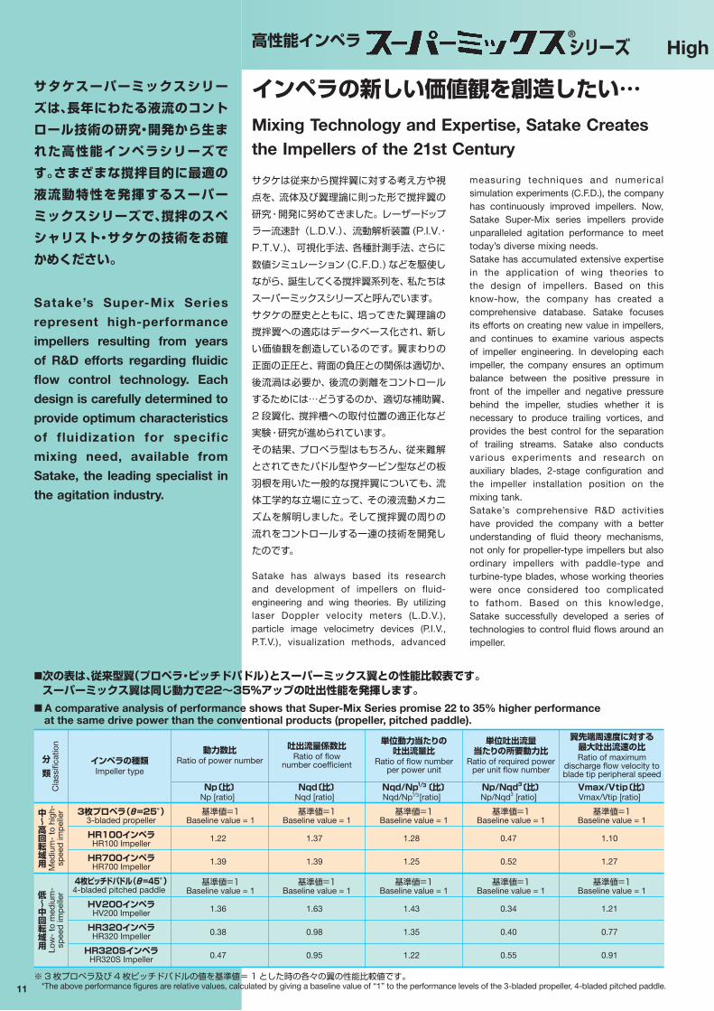
※ 3 枚プロペラ及び 4 枚ピッチドパドルの値を基準値= 1 とした時の各々の翼の性能比較値です。*The above performance figures are relative values, calculated by giving a baseline value of “1” to the performance levels of the 3-bladed propeller, 4-bladed pitched paddle.
インペラの新しい価値観を創造したい…Mixing Technology and Expertise, Satake Creates the Impellers of the 21st Century
インペラの種類Impeller type
動力数比Ratio of power number
吐出流量係数比Ratio of flow
number coefficient
単位動力当たりの吐出流量比
Ratio of flow numberper power unit
単位吐出流量当たりの所要動力比
Ratio of required powerper unit flow number
翼先端周速度に対する最大吐出流速の比Ratio of maximum
discharge flow velocity toblade tip peripheral speed
3枚プロペラ(θ=25°)3-bladed propeller
HR100インペラHR100 Impeller
HR700インペラHR700 Impeller
4枚ピッチドパドル(θ=45°)4-bladed pitched paddle
HV200インペラHV200 Impeller
HR320インペラHR320 Impeller
HR320SインペラHR320S Impeller
Np〔比〕Np [ratio]
Nqd〔比〕Nqd [ratio]
Nqd/Np 〔比〕Nqd/Np [ratio]
Np/Nqd3〔比〕Np/Nqd3 [ratio]
Vmax/Vtip〔比〕Vmax/Vtip [ratio]
1.22
1.39
1.36
0.38
0.47
基準値=1Baseline value = 1
基準値=1Baseline value = 1
分
類
Cla
ssifi
catio
n
中〜高回転域用 M
ediu
m-
to h
igh-
spee
d im
pel
ler
低〜中回転域用 Lo
w-
to m
ediu
m-
spee
d im
pel
ler
1.37
1.39
1.63
0.98
0.95
基準値=1Baseline value = 1
基準値=1Baseline value = 1
1.28
1.25
1.43
1.35
1.22
基準値=1Baseline value = 1
基準値=1Baseline value = 1
0.47
0.52
0.34
0.40
0.55
基準値=1Baseline value = 1
基準値=1Baseline value = 1
1.10
1.27
1.21
0.77
0.91
基準値=1Baseline value = 1
基準値=1Baseline value = 1
1⁄3
1⁄3
サタケは従来から撹拌翼に対する考え方や視点を、流体及び翼理論に則った形で撹拌翼の研究・開発に努めてきました。レーザードップラー流速計(L.D.V.)、流動解析装置 (P.I.V.・P.T.V.)、可視化手法、各種計測手法、さらに数値シミュレーション (C.F.D.) などを駆使しながら、誕生してくる撹拌翼系列を、私たちはスーパーミックスシリーズと呼んでいます。サタケの歴史とともに、培ってきた翼理論の撹拌翼への適応はデータベース化され、新しい価値観を創造しているのです。翼まわりの正面の正圧と、背面の負圧との関係は適切か、後流渦は必要か、後流の剥離をコントロールするためには…どうするのか、適切な補助翼、2 段翼化、撹拌槽への取付位置の適正化など実験・研究が進められています。その結果、プロペラ型はもちろん、従来難解とされてきたパドル型やタービン型などの板羽根を用いた一般的な撹拌翼についても、流体工学的な立場に立って、その液流動メカニズムを解明しました。そして撹拌翼の周りの流れをコントロールする一連の技術を開発したのです。
■次の表は、従来型翼(プロペラ・ピッチドパドル)とスーパーミックス翼との性能比較表です。スーパーミックス翼は同じ動力で22〜35%アップの吐出性能を発揮します。
■ A comparative analysis of performance shows that Super-Mix Series promise 22 to 35% higher performance at the same drive power than the conventional products (propeller, pitched paddle).
High Performance Impellers: Super-Mix Series高性能インペラ ®
シリーズ
measuring techniques and numerical simulation experiments (C.F.D.), the company has continuously improved impellers. Now, Satake Super-Mix series impellers provide unparalleled agitation performance to meet today’s diverse mixing needs.Satake has accumulated extensive expertise in the application of wing theories to the design of impellers. Based on this know-how, the company has created a comprehensive database. Satake focuses its efforts on creating new value in impellers, and continues to examine various aspects of impeller engineering. In developing each impeller, the company ensures an optimum balance between the positive pressure in front of the impeller and negative pressure behind the impeller, studies whether it is necessary to produce trailing vortices, and provides the best control for the separation of trailing streams. Satake also conducts various experiments and research on auxiliary blades, 2-stage configuration and the impeller installation position on the mixing tank.Satake’s comprehensive R&D activities have provided the company with a better understanding of fluid theory mechanisms, not only for propeller-type impellers but also ordinary impellers with paddle-type and turbine-type blades, whose working theories were once considered too complicated to fathom. Based on this knowledge, Satake successfully developed a series of technologies to control fluid flows around an impeller.

12
翼平面形状及び迎え角、カンバー比に対して検討を加え、翼先端ねじり下げ多段折り曲げ構造とし、翼背面における剥離を抑制することにより、低動力にて高吐出性を誇る省エネタイプの低剪断型軸流撹拌翼です。液一液混合、固一液分散、潰れやすく重くない粒子や、乳化マイクロカプセル(ラテックス etc.)の均一懸濁に適するとともに、優れた軸方向流動化作用を用い、多段撹拌における組み合わせにもその特性が発揮されます。
意匠登録済(日本)
A close review of the blade surface shape,
attack angle and camber ratio has led to
the twist-down leading edge, multi-bend
structure featured in the HR100 Impeller
designed to suppress flow separation
behind the blade. The result is the energy-
saving, low-shear axial flow impeller that
assures high discharge from a low power
source.
Ideal for mixing liquids, dispersing solid
and liquid mixtures, and creating uniform
suspension of fragile and lightweight
HR100 インペラ(中・高 Re 数域) HR100 Impeller (Medium and high Re number range)
■ L.D.V. による吐出性能比較結果■ Comparison of discharge
performance by L.D.V.
条件槽径:D 翼径:d 回転数:N 縦軸:吐出流速(Vq) 翼先端周速度(Vtip) 横軸:翼半径 D=490mm d/D=0.3 N=300min-1
Test conditions
Tank diameter: D Impeller diameter: d Rotation speed: N Vertical axis: Discharge velocity (Vq) Blade tip peripheral speed (Vtip) Horizontal axis: Impeller radius D = 490 mm d/D = 0.3 N = 300 min-1
4 枚ピッチドパドル(i=45°) 4-bladed pitched paddle
0.55
0.50
0.45
0.40
0.35
0.30
0.25
0.20
0.15
0.10
0.05
0.000.0 0.2 0.4 0.6 0.8 1.0 1.2
(d/2)/d
HR100 インペラ HR100 Impeller
軸中心
Axi
al c
ente
r 翼端
Bla
de
tip
Vq
/Vtip
三枚広幅翼と補助翼について研究を行った、サタケ独自の二重翼です。隙間フラップにおけるスロット効果によって、主翼部の背面に生じる剥離部を打ち消し、整流することにより、吐出流量や最大吐出速度を大幅に増大させることに成功しました。さらに回転軸を槽壁に近づけ、その近くに邪魔板一枚を設置するだけで、安定した単一ループの上下循環流を起こすことができます。
特許取得済(日本 PAT. No.3129487・米国・台湾)
The HV200 incorporates Satake’s original
double-blade structure, developed based
on extensive research of 3-wide-bladed
impellers and auxiliary blades. The slotted flap
effect cancels the flow separation generated
behind the main blades and rectifies the
streams to provide a significantly increased
discharge rate and maximum discharge
velocity. By positioning the shaft close to
the tank wall and installing a baffle near
the impeller, a stable single-loop vertically
circulating flow can be generated.
This impeller is suitable for mixing liquids
and the dispersion of low-viscosity slurries.
Patent registered in Japan (PAT. No. 3129487), U.S.A. and Taiwan
■ L.D.V. による吐出性能比較結果■ Comparison of discharge
performance by L.D.V.
HV200 インペラ(中・高 Re 数域) HV200 Impeller (Medium and high Re number range)
条件槽径:D 翼径:d 回転数:N 縦軸:吐出流速(Vq) 翼先端周速度(Vtip)横軸:翼半径 D=490mm d/D=0.3 N=300min-1
Test conditions
Tank diameter: D Impeller diameter: d Rotation speed: N Vertical axis: Discharge velocity (Vq) Blade tip peripheral speed (Vtip) Horizontal axis: Impeller radius D = 490 mm d/D = 0.3 N = 300 min-1
0.55
0.50
0.45
0.40
0.35
0.30
0.25
0.20
0.15
0.10
0.05
0.000.0 0.2 0.4 0.6 0.8 1.0 1.2
軸中心
Axi
al c
ente
r 翼端
Bla
de
tipHV200 インペラ HV200 Impeller
(d/2)/d
Vq
/Vtip
4 枚ピッチドパドル(i=45°) 4-bladed pitched paddle
■ HR100 インペラのフローパターン■ Flow pattern of the HR100 Impeller
C.F.D. による数値シミュレーション結果 C.F.D. numerical simulation result
particles and emulsified micro-capsules
(Latex, etc), the HR100 Impeller’s axial
fluidization may also be combined with
multi-stage agitation processes to get the
desired result.
Design registered in Japan
SeriesHigh Performance Impellers: Super-Mix Series

高性能インペラ ®
シリーズ
13
HR320
前進翼にしますと、翼背面における圧力分布によって表面の流れが内側に向かいます。それとともに、翼先端に向かって迎え角を減らす折り曲げ構造として、ねじり下げと同じ効果を担うことになります。これらの効果から、翼先端における流れの剥離を防ぎ吐出能力を向上させたインペラです。液面変動のない高レイノルズ数域の濃度や温度を均一に維持しつつ、大吐出流量を必要とする撹拌に適しています。
特許取得済(日本・韓国)意匠登録済(日本)
The advance blade angle causes the liquid
flow near the blade surface to move toward
the inside, due to the pressure distribution
behind the blades. The bend structure
features a reduced attack angle at the
leading edge, to create a downward twisting
force. These effects combine to prevent flow
separation at the blade tips and improve
discharge performance.
The HR320 Impeller meets agitation
needs for large discharge rates, such as
for uniform distribution of concentration
and temperature in the high Reynolds
number range, with minimum liquid surface
fluctuation.
Patent registered in Japan and South KoreaDesign registered in Japan
■ L.D.V. による吐出性能比較結果■ Comparison of discharge
performance by L.D.V.
■ HR320 インペラのフローパターン■ Flow pattern of the HR320
Impeller
前進翼効果に加え、翼表面の圧力をコントロールし、高い迎え角において翼表面の剥離を防ぎ、高吐出速度を得るために、航空機に用いる隙間フラップと同じ効果の二重翼構造としています。また、サタケ独自の翼端板を設けました。これによってスタビライザーリングを不要とし、液面通過運転を可能にしました。液面通過運転や翼取り付け高さが、極端に低い撹拌、及び固一液系の撹拌にすぐれています。
The HR320S Impeller generates an advance
blade effect and controls the blade surface
pressure. Combined with a large attack angle,
these features prevent flow separation on the
blade surfaces. To achieve high discharge
velocity, the impeller incorporates a double-
blade structure, which provides the similar
effects created by the slotted flaps of an
airplane. The HR320S is also equipped
with Satake’s original blade tip boards. They
eliminate the need for stabilizer rings and allow
the impeller to continue operation that liquid
level passes over impeller position.
The HR320S Impeller is suited for operation
that liquid level passes over impeller
position, for applications in which the blade
installation height is limited, and for agitation
of solid and liquid mixtures.
HR320S
条件槽径:D翼径:d回転数:N縦軸:吐出流速(Vq) 翼先端周速度(Vtip)横軸:翼下部半径D=490mmd/D=0.3N=300min-1
Test conditions
Tank diameter: DImpeller diameter: dRotation speed: NVertical axis: Discharge velocity (Vq) Blade tip peripheral speed (Vtip) Horizontal axis: Lower Impeller radiusD = 490 mmd/D = 0.3N = 300 min-1
P.T.V. 流動解析結果P.T.V. flow analysis result
0.55
0.50
0.45
0.40
0.35
0.30
0.25
0.20
0.15
0.10
0.05
0.000.0 0.2 0.4 0.6 0.8 1.0 1.2
Vq
/Vtip
HR320 インペラ HR320 Impeller
軸中心
Axi
al c
ente
r 翼端
Bla
de
tip
(d/2)/d
4 枚ピッチドパドル(i=45°) 4-bladed pitched paddle
HR320S Impeller (Medium and high Re number range)インペラ(中・高 Re 数域)
HR320 Impeller (Medium and high Re number range)インペラ(中・高 Re 数域)
High Performance Impellers: Super-Mix Series
C.F.D. による数値シミュレーション結果C.F.D. numerical simulation result
■翼近傍の流動状態■ Flow condition near the blade
Series
14
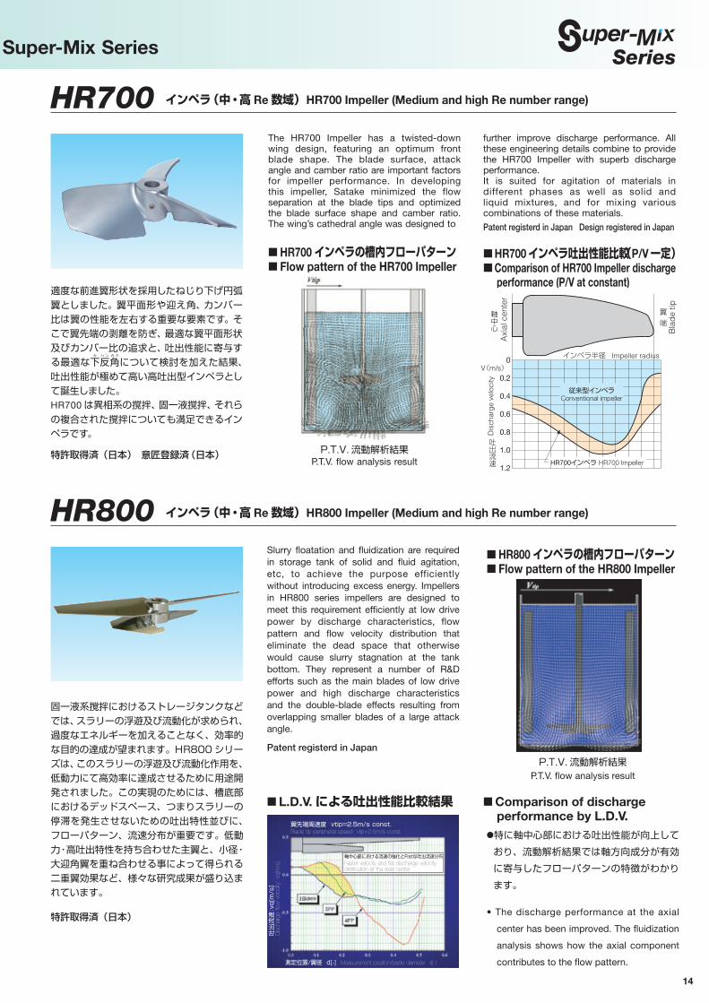
適度な前進翼形状を採用したねじり下げ円弧翼としました。翼平面形や迎え角、カンバー比は翼の性能を左右する重要な要素です。そこで翼先端の剥離を防ぎ、最適な翼平面形状及びカンバー比の追求と、吐出性能に寄与する最適な下
カ
反ハ ン
角カ ク
について検討を加えた結果、吐出性能が極めて高い高吐出型インペラとして誕生しました。HR700 は異相系の撹拌、固一液撹拌、それらの複合された撹拌についても満足できるインペラです。
特許取得済(日本) 意匠登録済(日本)
The HR700 Impeller has a twisted-down wing design, featuring an optimum front blade shape. The blade surface, attack angle and camber ratio are important factors for impeller performance. In developing this impeller, Satake minimized the flow separation at the blade tips and optimized the blade surface shape and camber ratio. The wing’s cathedral angle was designed to
further improve discharge performance. All these engineering details combine to provide the HR700 Impeller with superb discharge performance.It is suited for agitation of materials in different phases as well as solid and liquid mixtures, and for mixing various combinations of these materials.
Patent registerd in Japan Design registered in Japan
HR700 インペラ(中・高 Re 数域) HR700 Impeller (Medium and high Re number range)
■ HR700 インペラの槽内フローパターン■ Flow pattern of the HR700 Impeller
翼先端
P.T.V. 流動解析結果P.T.V. flow analysis result
High Performance Impellers: Super-Mix Series
HR800 インペラ(中・高 Re 数域) HR800 Impeller (Medium and high Re number range)
固一液系撹拌におけるストレージタンクなどでは、スラリーの浮遊及び流動化が求められ、過度なエネルギーを加えることなく、効率的な目的の達成が望まれます。HR800 シリーズは、このスラリーの浮遊及び流動化作用を、低動力にて高効率に達成させるために用途開発されました。この実現のためには、槽底部におけるデッドスペース、つまりスラリーの停滞を発生させないための吐出特性並びに、フローパターン、流速分布が重要です。低動力・高吐出特性を持ち合わせた主翼と、小径・大迎角翼を重ね合わせる事によって得られる二重翼効果など、様々な研究成果が盛り込まれています。
特許取得済(日本)
Slurry floatation and fluidization are required in storage tank of solid and fluid agitation, etc, to achieve the purpose efficiently without introducing excess energy. Impellers in HR800 series impellers are designed to meet this requirement efficiently at low drive power by discharge characteristics, flow pattern and flow velocity distribution that eliminate the dead space that otherwise would cause slurry stagnation at the tank bottom. They represent a number of R&D efforts such as the main blades of low drive power and high discharge characteristics and the double-blade effects resulting from overlapping smaller blades of a large attack angle.
Patent registerd in Japan
●特に軸中心部における吐出性能が向上しており、流動解析結果では軸方向成分が有効に寄与したフローパターンの特徴がわかります。
• The discharge performance at the axial
center has been improved. The fluidization
analysis shows how the axial component
contributes to the flow pattern.
■ HR800 インペラの槽内フローパターン■ Flow pattern of the HR800 Impeller
P.T.V. 流動解析結果P.T.V. flow analysis result
■ L.D.V. による吐出性能比較結果翼先端周速度 vtip=2.5m/s const.Blade tip peripheral speed vtip=2.5m/s const.
測定位置/翼径 d[-] Measurement position/blade diameter d[-]
吐出
流速
:vq
[m/s
]D
isch
arge
flow
vel
ocity
: vq
[m/s
]
軸中心部における流速の強化とFlatな吐出流速分布Faster velocity and flat discharge velocity distribution at the axial center
■ Comparison of discharge performance by L.D.V.
■ HR700 インペラ吐出性能比較(P/V 一定)■ Comparison of HR700 Impeller discharge
performance (P/V at constant)
0
0.2
0.4
0.6
0.8
1.0
1.2 HR700インペラ HR700 Impeller
従来型インペラConventional impeller
軸中心
V(m/s)インペラ半径 Impeller radius
翼
端
Axi
al c
ente
r
吐出流速
Dis
char
ge
velo
city
Bla
de
tip
高性能インペラ ®
シリーズ
15
High Performance Impellers: Super-Mix Series
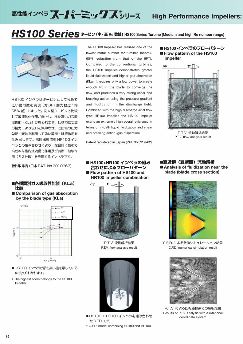
HS100 インペラはタービンとして極めて低い動力数を実現(対 6FT 動力数比:約65% 減)しました。従来型タービンと比較して液流動化作用が向上し、また高いガス吸収性能(KLa)が得られます。低動力にて翼の揚力により流れを集中させ、吐出場の圧力勾配・変動を利用して強い剪断・破壊作用を生み出します。高吐出軸流型 HR100 インペラとの組み合わせにより、総合的に極めて高効率な槽内液流動化作用及び剪断・破壊作用(ガス分散)を発揮するインペラです。
特許取得済(日本 PAT. No.3919262)■翼近傍(翼断面)流動解析■ Analysis of fluidization near the
blade (blade cross section)
■ HS100 インペラのフローパターン■ Flow pattern of the HS100
Impeller
P.T.V. 流動解析結果P.T.V. flow analysis result
C.F.D. による数値シミュレーション結果C.F.D. numerical simulation result
P.T.V. による回転座標系での解析結果Results of P.T.V. analysis with a rotational
coordinate system
● HS100 インペラが最も高い値を示しているのが良くわかります。
• The highest score belongs to the HS100 Impeller
■各種翼別ガス吸収性能値(KLa)比較
■ Comparison of gas absorption by the blade type (KLa)
102
KLa
(hr-1
)
6FT
6CC
HS100
Pgv (kW/m3)
101
10-1
100
Pgv-KLa
The HS100 Impeller has realized one of the
lowest motor number for turbines (approx.
65% reduction from that of the 6FT).
Compared to the conventional turbines,
the HS100 Impeller demonstrates greater
liquid fluidization and higher gas absorption
(KLa). It requires only a low power to create
enough lift in the blade to converge the
flow, and produces a very strong shear and
breaking action using the pressure gradient
and fluctuation in the discharge field.
Combined with the high discharge axial flow
type HR100 impeller, the HS100 Impeller
exerts an extremely high overall efficiency in
terms of in-bath liquid fluidization and shear
and breaking action (gas dispersion).
Patent registered in Japan (PAT. No.3919262)
HS100 Seriesタービン(中・高 Re 数域) HS100 Series Turbine (Medium and high Re number range)
P.T.V. 流動解析結果P.T.V. flow analysis result
■ HS100+HR100 インペラの組み合わせによるフローパターン
■ Flow pattern of HS100 and HR100 Impeller combination
● HS100 + HR100 インペラを組み合わせた C.F.D. モデル
• C.F.D. model combining HS100 and HR100
Vtip

Series
16
High Performance Impellers: Super-Mix Series
及ぶ均一性の高いフローパターンと分散性能は、比較的シンプルな構造から医薬・バイオケミカル・食品関連での重要なプロセスにおいて評価されており、その他反応系でのプロセスをはじめ液排出時の均一性を求められる撹拌目的にその威力を発揮します。
撹拌目的に応じて様々なバリエーションがあり、翼の枚数をはじめ、湾曲タイプ、2 段折り曲げタイプ、高吐出性能型軸流翼の組み合わせなどにより、はじめてその性能が発揮されます。また独特な形状と取り付け方法、槽内全域に
HS600 Series インペラ(中・高 Re 数域) HS600 Series Impellers (Medium and high Re number range)
HS600 シリーズインペラは 、 単に翼単体では
なく撹拌槽をはじめとする撹拌装置として研究 ・ 開発されました。槽内における分散均一性能に優れ 、 固一液系撹拌及びスラリー撹拌などでは 、 低回転 ・ 低動力にて流動化を可能としました。また 、 槽底部に近接して設置されることから液面変動にも強く 、 更に抜き出しにおける粒子の均一性に優れた特性を発揮するとともに 、 静翼との組み合わせなど圧力場をコントロールすることにより 、 剪断力のコントロールを可能にしました。その独特な形状は 、 撹拌装置として槽内の圧力分布の研究結果から生み出されており 、 広幅大型翼でも困難であった大循環流型のフローパターンと、 優れた高吐出性能と 、 低動力化を実現しました。高吐出軸流型 HR100 インペラとの組み合わせにより 、 高液深撹拌においても同様の性能を発揮します。
特許取得済(日本)意匠登録済(日本)
The impellers in the HS600 Series are the
product of research and development
efforts aimed not only at the impeller but
the ent ire mixer, including the mixing
tank. These impellers promise excellent
uniformity of dispersion in the tank and
fluidization of material in solid-liquid mixing
and slurry mixing under low-revolution
and low dynamic power conditions. Their
proximity to the tank bottom makes them
less susceptible to liquid surface fluctuation
and ensures particle uniformity. Shearing
force control is achieved by controlling
pressure fields, such as the combination of
the impellers and static blades. The unique
profile is the result of research into pressure
distribution in the tank serving as a mixer. It
enables a large circulation flow pattern and
an extremely high discharge capability that
cannot be expected even from large and
wide blades. At the same time, the power
requirement is low.
Similar performance is available for deeper
liquid mixing by combining HS600 Series
impellers with the high discharge axial flow
type HR100 impeller.
Patent registerd in JapanDesign registered in Japan
■ HS606 インペラのフローパターン■ Flow pattern of the HS606
Impeller
■ HS606 + HR100 インペラの組み合わせによるフローパターン
■ Flow pattern of HS606 and HR100 Impeller combination
P. T .V. 流動解析結果P.T.V. flow analysis result
P. T .V. 流動解析結果P.T.V. flow analysis result
■ HS600 シリーズのインペラ ■ HS600 Series ImpellersNumerous variations are possible, to meet
specific requirements. Best performance is
achieved by combining the optimum number
and type of blades (curved type, two-way
bend type, high discharge axial flow type,
etc.).
HS600 Series Impellers — with their unique
shape and mounting method, uniform
flow pattern and dispersion performance
in the tank, as wel l as their relat ively
simple structure — are highly rated by
pharmaceutical, biochemical and food
industry professionals who depend on them
in their key processes. Satake impellers are
also preferred for other reactive processes
and mixing needs where uniform discharge
of liquid is critical.
2 枚翼 2-bladed impeller
(HS602) 3 枚翼 3-bladed impeller
(HS603)
4 枚翼 4-bladed impeller
(HS604)
6 枚翼 6-bladed impeller
(HS606)
17
高性能インペラ ®
シリーズ High Performance Impellers: Super-Mix Series
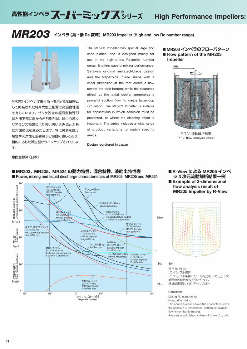
■ R-View による MR205 インペラ 3 次元流動解析結果一例
■ Example of 3-dimensional flow analysis result of MR205 Impeller by R-View
NTM[-]
Np[-]
Nqd[-]
103
102
101
100
100 101 102 103 104 10510-1
4-bladed pitched paddle2-baffles, 2 stages Np
MR203·MR205 Impellernon-baffle Np
MR203·MR205インペラバッフルなし Np
MR524インペラバッフルなし NTM
MR524インペラバッフルなし Np
アンカー翼 Np
アンカー翼 NTM
4枚ピッチパドル 2-バッフル(2段)Np
ヘリカルリボン翼 NpHelical ribbon Np
ヘリカルリボン翼 NTM
Helical ribbon NTM
MR524 Impellernon-baffle NTM
MR203インペラバッフルなし NTM
MR203 Impellernon-baffle NTM
MR524 Impellernon-baffle Np
MR205 Impeller2-baffles Nqd
MR205 Impeller2-baffles NTM
Anchor⦆Np
Anchor NTM
MR205インペラバッフルなし NTM
MR205インペラ2-バッフル NTM
MR205インペラ2-バッフル Nqd
レイノルズ数 Re[-]
MR205 Impellernon-baffle NTM
4-bladed pitched paddle2-baffles, 2 stages NTM
4枚ピッチパドル2-バッフル(2段) NTM
無次元混合時間数
動力数
吐出流量係数
Pow
er n
umb
erFl
ow n
umb
er c
oeffi
cien
t MR205インペラ2-バッフル NpMR205 Impeller2-baffles Np
Reynolds number
Nqd
Np
NTMDim
ensi
onle
ss m
ixin
g tim
e co
unt
■ MR203、MR205、MR524 の動力特性、混合特性、液吐出特性表■ Power, mixing and liquid discharge characteristics of MR203, MR205 and MR524
条件撹拌 Re 数 50ノンバッフル撹拌ノンバッフル条件において有効な 3 次元上下大循環流の特徴が良く分かります。解析結果提供:(株)アールフロー
Conditions
Mixing Re number: 50Non-baffle mixingThe analysis result shows the characteristics of the effective 3-dimensional vertical circulation flow in non-baffle mixing.Analysis result data courtesy of Rflow Co., Ltd.
MR203 インペラ(高・低 Re 数域) MR203 Impeller (High and low Re number range)
MR203 インペラは主に高〜低 Re 域を目的と
して開発された特殊大型広幅翼で高混合性能を有しています。サタケ独自の鋸刃型特殊形状と槽下部に向かう台形型形状、軸中心部クリアランス効果により強い吸い込み流とともに大循環流を生みだします。特に付着を嫌う場合や洗浄性を重要視する場合に適しており、目的に応じた派生型がラインナップされています。
意匠登録済(日本)
The MR203 Impeller has special large and
wide blades, and is designed mainly for
use in the high-to-low Reynolds number
range. It offers superb mixing performance.
Satake’s original serrated-blade design
and the trapezoidal blade shape with a
wider dimension at the root create a flow
toward the tank bottom, while the clearance
effect at the axial center generates a
powerful suction flow, to create large-loop
circulation. The MR203 Impeller is suitable
for applications in which adhesion must be
prevented, or where the cleaning effect is
important. The series includes a wide range
of product variations to match specific
needs.
Design registered in Japan
■ MR203 インペラのフローパターン■ Flow pattern of the MR203
Impeller
P.T.V. 流動解析結果P.T.V. flow analysis result
18
Series
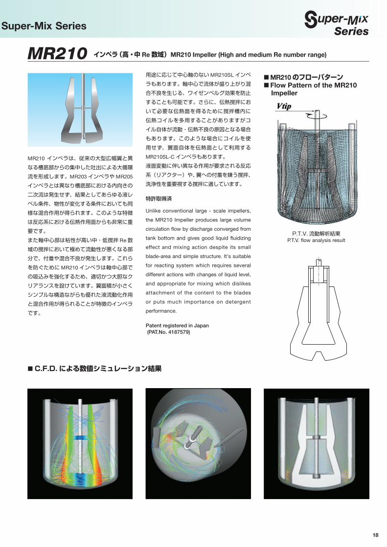
■ C.F.D. による数値シミュレーション結果
MR210 インペラ(高・中 Re 数域) MR210 Impeller (High and medium Re number range)
MR210 インペラは、従来の大型広幅翼と異なる槽底部からの集中した吐出による大循環流を形成します。MR203 インペラや MR205
インペラとは異なり槽底部における内向きの二次流は発生せず、結果としてあらゆる液レベル条件、物性が変化する条件においても同様な混合作用が得られます。このような特徴は反応系における伝熱作用面からも非常に重要です。また軸中心部は粘性が高い中・低撹拌 Re 数域の撹拌において極めて流動性が悪くなる部分で、付着や混合不良が発生します。これらを防ぐために MR210 インペラは軸中心部での吸込みを強化するため、適切かつ大胆なクリアランスを設けています。翼面積が小さくシンプルな構造ながらも優れた液流動化作用と混合作用が得られることが特徴のインペラです。
用途に応じて中心軸のない MR210SL インペラもあります。軸中心で流体が盛り上がり混合不良を生じる、ワイゼンベルグ効果を防止することも可能です。さらに、伝熱撹拌において必要な伝熱面を得るために撹拌槽内に伝熱コイルを多用することがありますがコイル自体が流動・伝熱不良の原因となる場合もあります。このような場合にコイルを使用せず、翼面自体を伝熱面として利用するMR210SL-C インペラもあります。液面変動に伴い異なる作用が要求される反応系(リアクター)や、翼への付着を嫌う撹拌、洗浄性を重要視する撹拌に適しています。
特許取得済
Unlike conventional large - scale impellers,
the MR210 Impeller produces large volume
circulation flow by discharge converged from
tank bottom and gives good liquid fluidizing
effect and mixing action despite its small
blade-area and simple structure. It's suitable
for reacting system which requires several
different actions with changes of liquid level,
and appropriate for mixing which dislikes
attachment of the content to the blades
or puts much importance on detergent
performance.
Patent registered in Japan (PAT.No. 4187579)
■ MR210 のフローパターン■ Flow Pattern of the MR210
Impeller
High Performance Impellers: Super-Mix Series
P.T.V. 流動解析結果P.T.V. flow analysis result

19
高性能インペラ ®
シリーズ
■ MR205 インペラのフローパターン■ Flow pattern of the MR205
Impeller
MR205 インペラ(中・低 Re 数域) MR205 Impeller (Medium and low Re number range)
二重翼効果をもつ大型広幅翼です。主翼前面の正圧部と補助翼面の負圧部分との間に大きな圧力差が生じ、その圧力差により高粘度液体でも半径方向に強力な吐出流が得られます。また、主翼部下方の翼径を大きく台形型とすることで、槽底から液表面に向かう強い上昇流も生まれます。さらに、主翼切り欠き部をノコ歯状にすることで混合不良部
(通称ドーナツリング)を完全に除いた均一混合を実現しました。特に比重差や粘度差のある液体の混合、及び高濃度スラリーの懸濁などにも適しています。
実用新案取得済(日本)特許出願中(日本・台湾)意匠登録済(日本)
The MR205 Impeller is a large, wide-blade
impeller with a double-blade structure. The
large pressure gap generated between the
positive pressure in front of the main blades
and the negative pressure on the auxiliary
blades produces a strong discharge flow
in the radial direction, even with a highly
viscous liquid. The main blades, which feature
a trapezoidal shape at the lower section,
generate a powerful upward stream from the
tank bottom toward the liquid surface. The
serration on the notch of the main blades
eliminates incomplete mixing (known as a
donut ring) and ensures thorough and uniform
agitation.
Registered utility modelPatent pending in Japan and TaiwanDesign registered in Japan
翼回転方向Anti-direction rotation
翼回転方向Anti-direction rotation
標準大型広幅断面Cross section of standard
large wide blade
MR205 二重翼断面Cross section of double-blade structure of MR205 Impeller
P.T.V. 流動解析結果P.T.V. flow analysis result
C.F.D. による数値シミュレーション結果 C.F.D. numerical simulation result
■脱色反応による混合時間の比較(MR205:ヘリカルリボン翼)■ Comparison of mixing time by decoloring reaction of dye (MR205 vs. Helical ribbon impeller)MR205 インペラ MR205 Impeller
撹拌条件:単位容積あたりの所要動力 Pv=1.1kW/m3 const レイノルズ数(Re)=10 オーダー 粘度(µ)=5,000mpa·sAgitation conditions: Required power per unit volume Pv = 1.1 kW/m3 constant Reynolds number (Re) = 10 order Viscosity (µ) = 5,000 mpa·s
ヘリカルリボン翼 Helical ribbon impeller
翼形状Blade shape
スタート(脱色)Start (decoloring)
50 秒50 sec.
100 秒100 sec.
150 秒150 sec.
200 秒200 sec.
High Performance Impellers: Super-Mix Series
P.T.V. 流動解析結果と C.F.D. による数値シミュレーション結果の比較Comparison of P.T.V. flow analysis result and C.F.D. numerical simulation result
20
Series
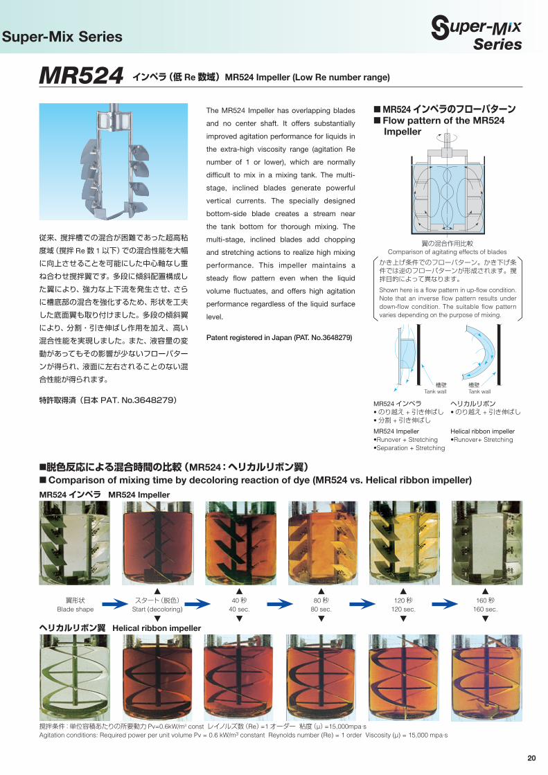
翼の混合作用比較Comparison of agitating effects of blades
MR524 インペラ(低 Re 数域) MR524 Impeller (Low Re number range)
従来、撹拌槽での混合が困難であった超高粘度域(撹拌 Re 数 1 以下)での混合性能を大幅に向上させることを可能にした中心軸なし重ね合わせ撹拌翼です。多段に傾斜配置構成した翼により、強力な上下流を発生させ、さらに槽底部の混合を強化するため、形状を工夫した底面翼も取り付けました。多段の傾斜翼により、分割・引き伸ばし作用を加え、高い混合性能を実現しました。また、液容量の変動があってもその影響が少ないフローパターンが得られ、液面に左右されることのない混合性能が得られます。
特許取得済(日本 PAT. No.3648279)
The MR524 Impeller has overlapping blades
and no center shaft. It offers substantially
improved agitation performance for liquids in
the extra-high viscosity range (agitation Re
number of 1 or lower), which are normally
difficult to mix in a mixing tank. The multi-
stage, inclined blades generate powerful
vertical currents. The specially designed
bottom-side blade creates a stream near
the tank bottom for thorough mixing. The
multi-stage, inclined blades add chopping
and stretching actions to realize high mixing
performance. This impeller maintains a
steady flow pattern even when the liquid
volume fluctuates, and offers high agitation
performance regardless of the liquid surface
level.
Patent registered in Japan (PAT. No.3648279)
MR524 インペラ• のり越え + 引き伸ばし • 分割 + 引き伸ばしMR524 Impeller•Runover + Stretching •Separation + Stretching
ヘリカルリボン• のり越え + 引き伸ばし
Helical ribbon impeller•Runover+ Stretching
■ MR524 インペラのフローパターン■ Flow pattern of the MR524
Impeller
槽壁Tank wall
槽壁Tank wall
■脱色反応による混合時間の比較(MR524:ヘリカルリボン翼)■ Comparison of mixing time by decoloring reaction of dye (MR524 vs. Helical ribbon impeller)MR524 インペラ MR524 Impeller
撹拌条件:単位容積あたりの所要動力 Pv=0.6kW/m3 const レイノルズ数(Re)=1 オーダー 粘度(µ)=15,000mpa·sAgitation conditions: Required power per unit volume Pv = 0.6 kW/m3 constant Reynolds number (Re) = 1 order Viscosity (µ) = 15,000 mpa·s
ヘリカルリボン翼 Helical ribbon impeller
翼形状Blade shape
スタート(脱色)Start (decoloring)
40 秒40 sec.
80 秒80 sec.
120 秒120 sec.
160 秒160 sec.
High Performance Impellers: Super-Mix Series
かき上げ条件でのフローパターン。かき下げ条件では逆のフローパターンが形成されます。撹拌目的によって異なります。Shown here is a flow pattern in up-flow condition. Note that an inverse flow pattern results under down-flow condition. The suitable flow pattern varies depending on the purpose of mixing.

RBミキシングシステム RB Mixing System
撹拌は一般的には、インペラによって液を流動化させて行います。RB ミキシングシステムにおけるインペラの役目は、積極的な撹拌ではありません。ヒントは自然界の流れと整流作用、そして家屋をも吸い上げてしまう竜巻にありました。「その整流作用と竜巻を撹拌槽内で造り出したらどうなるのか」と考えたのです。インペラによって撹拌槽内に旋回流を作り出し、撹拌槽底部で中心に向かう旋回流(境界層効果)を効率良く竜巻状の上昇流に交換する『放射状ブレード』から構成され、従来の撹拌に対する概念からは考えられないフローパターンを形成するシステムとして確立しました。旋回流が主流のため、これによって翼近傍での相対速度差を減じることにより、バイオをはじめ薬品、水処理など低剪断撹拌を効率よく行うことが可能です。また、もう一つの特徴でもある短いミキシングシャフトは、固体粒子に埋まった翼の起動トルクを心配する必要はありません。
特許取得済(日本 PAT. No.3578782)
Generally, agitation is achieved by an
impeller, which causes fluidization of a liquid.
In the RB mixing system, however, the
impeller does not play an active role. Inspired
by natural flows and rectifications and, of all
things, tornadoes that are powerful enough
to lift a house, special efforts were made
to create rectification and a tornado in the
agitation tank. The RB system consists of
an impeller, which generates a swirling flow,
and radial blades that convert the current
(boundary layer effect) swirling towards
the center on the bottom of the tank into
an upward, tornado-like flow. This system
provides a flow pattern radically different
from that envisioned in the conventional
concept of agitation. Since the swirling flow
is a main current, it reduces the relative
speed difference of the flow near the blade.
This provides an effective low shearing
force, thus making it ideal for agitation of
biochemicals and pharmaceuticals, and
for water treatment. The RB mixing system
features a short mixing shaft to assure that
starting torque is not inhibited by solid
particles adhered on the impeller.
Patent registered in Japan (PAT. No.3578782)
液深が槽径の 5 倍のフローパターンFlow pattern with liquid having depth five
times greater than the tank diameter
従来にない高い上昇流Powerful upward flow not generated in any conventional system
■ RB ミキシングシステム槽内 フローパターン
■ Flow pattern of the RB mixing system
■従来型の撹拌方式■ Conventional mixing system
■ RB ミキシングシステム■ Super mix RB system
■各撹拌システムの比較表■ Table of comparison of mixing systems
撹 拌 方 式
スーパーミックスRBミキシングシステム
4枚邪魔板付撹拌システム
邪魔板無し撹拌システム
Mixing methods
判 定
Judgment
87
30
15
0.4
0.8
0.4
SUPER-MIX RB mixing system
Mixing system with four baffle plates
Mixing system with no baffle plates
最大上昇流速度係数%(対翼先端速度比率)Maximum upflow speed factor (%)
(the ratio to the wing tip speed)
翼・液相対速度差係数(剪断速度比率)
Relative speed difference factor of wing and liquid (shearing speed ratio)
撹拌可能な最大縦長比Z/D 比
Mixable Z/D ratio
低剪断で強力な循環流形成
Formation of strong circulating flow with low share
剪断力が強いStrong sharing force
5以上可能5 or more
2程度迄Up to 2 approx.
1.5程度迄Up to 1.5 approx.
上下循環流形成が弱いFormation of weak
circulating flow in both directions (up/down)
■用 途■ Application① バイオプロセスの撹拌 ② 水処理プロセスの撹拌 ③ 連続処理のスラリー撹拌 ④ 縦長槽の均一撹拌
① Bio-process mixing ② Mixing in water treatment process ③ Slurry mixing in continuous treatment ④ Uniform mixing in a longitudinal bath
21
高性能インペラ ®
シリーズSeriesHigh Performance Impellers: Super-Mix Series
C.F.D. による数値シミュレーション結果C.F.D. numerical simulation result
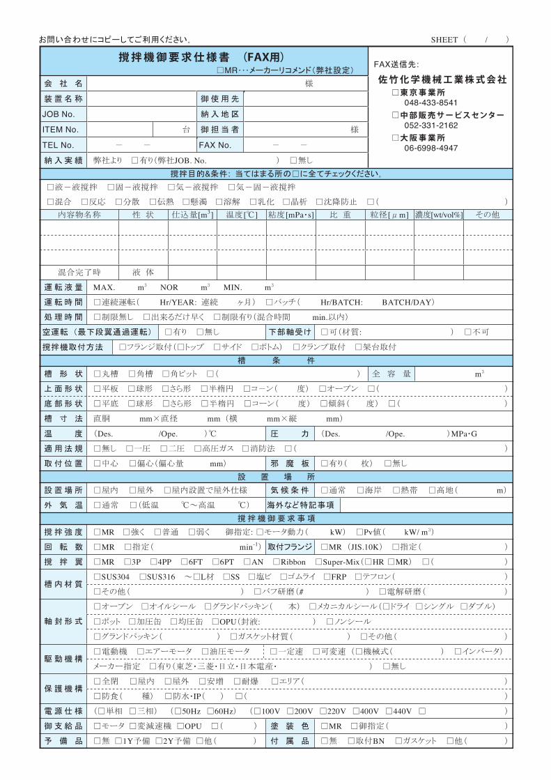
SHEET /
MR
JOB No.
ITEM No.
TEL No. FAX No.
JOB. No.
FAX :
048-433-8541
052-331-2162
06-6998-4947
& :
[m3] [ ] [mPa s] [ m] [wt/vol%]
MAX. m NOR m MIN. m
Hr/YEAR: Hr/BATCH: BATCH/DAY
min.
:
m
mm mm mm mm
Des. /Ope. Des. /Ope. MPa G
mm
m
MR kW Pv kW/ m
MR min-1 MR JIS.10K
MR 3P 4PP 6FT 6PT AN Ribbon Super-Mix HR MR
SUS304 SUS316 L SS FRP
#
OPU :
IP
50Hz 60Hz 100V 200V 220V 400V 440V
OPU MR
1Y 2Y BN
撹拌機御要求仕様書 (FAX用)
佐竹化学機械工業株式会社東京事業所
中部販売サービスセンター
大阪事業所

スーパーミックス®は、佐竹化学機械工業の登録商標です。
(Overseas affiliated company)
China Satake (Shanghai) Trading Co., Ltd. Room 9002, Yong Xin Building, 887 Huaihai Road (M), Shanghai 200020, China Tel. 86-21-6437-7101 Fax. 86-21-6437-7102
Dalian Satake Chemical Equipment Co., Ltd. No.8 Qingdao Lu Jinhua Street Lvshun Economic Development Zone 116052, Dalian, ChinaTel. 86-411-3936-8689 Fax. 86-411-3936-8690
Korea Hado Co., Ltd. 95, Gajaeul-ro, Seo-Gu, Incheon 22830, Korea Tel. 82-32-583-6321 Fax. 82-32-583-6329
Taiwan Kwan-Tai Machinery Co., Ltd. 15, Kegong 7th Rd., Douliou City, Yunlin County 64001, Taiwan Tel. 886-5-551-7858 Fax. 886-5-551-7921
Satake Asia Sales & Services Co.,Ltd. No.21, Ln.86, Wugong 3rd Rd., Xinzhuang Dist., New Taipei City 24889, Taiwan Tel. 886-2-2298-4880 Fax. 886-2-2298-4881
(海外関連会社)中国 佐竹(上海)貿易有限公司 〒200010 上海市黄浦区人民路885号淮海中華大厦605室 Tel. 86-21-6437-7101 Fax. 86-21-6437-7102 大連佐竹化工機械有限公司 〒116052 大連市旅順経済開発区金華街青島路8号 Tel. 86-411-3936-8689 Fax. 86-411-3936-8690韓国 株式会社夏都 〒22830 仁川廣域市西區Gajaeul-ro 95 Tel. 82-32-583-6321 Fax. 82-32-583-6329台湾 光太機械廠股份有限公司 〒64001 雲林県斗六市科工七路15号 Tel. 886-5-551-7858 Fax. 886-5-551-7921
佐竹亞州股份有限公司 〒24899 新北市新莊區五丁三路86巷21號 Tel. 886-2-2298-4880 Fax. 886-2-2298-4881
お客様が満足し 安心して使用できる 製品づくりに徹する
大 阪 事 業 所・工 場 〒570-0035 大 阪 府 守 口 市 東 光 町 2 - 1 8 - 8 ☎(06) 6992-0371
東 京 事 業 所・工 場 〒335-0021 埼 玉 県 戸 田 市 新 曽 6 6 ☎(048) 433-8711
中部販売サービスセンター 〒460-0021 愛知県名古屋市中区平和1-21 - 9 ☎(052) 331-6691撹 拌 技 術 研 究 所 〒335-0021 埼 玉 県 戸 田 市 新 曽 6 0 ☎(048) 441-9200
Osaka Of fice 2-18-8, T oko-cho, Moriguchi-shi, Osaka 570-0035, Japan and Plant: Phone: 81-6-6992-0371 Fax: 81-6-6998-4947Tokyo Office 66, Niizo, Toda-shi, Saitama 335-0021, Japan and Plant: Phone: 81-48-433-8711 Fax: 81-48-433-8541Chubu Sales 1-21-9, Heiwa, Naka-ku, Nagoya-shi, Aichi 460-0021, Japan Service Center: Phone: 81-52-331-6691 Fax: 81-52-331-2162Mixing Technology 60, Niizo, T oda-shi, Saitama 335-0021, Japan Laboratory: Phone: 81-48-441-9200 Fax: 81-48-444-1042
URL: http://www.satake.co.jp