Embed Size (px)
Citation preview
S I G N A L S T H E B E S T
6 3 3 7
2 - w i r e H A R T ®
T r a n s m i t t e r
N o . 6 3 3 7 V 1 0 1 - U KF r o m s e r . n o . 1 1 0 9 4 4 3 4 5

1350
PR electronics A/S tilbyder et bredt program af analoge og digitale signalbehandlingsmoduler til industriel automation. Programmet består af Isolatorer, Displays, Ex-barrierer, Temperaturtransmittere, Universaltransmittere mfl. Vi har modulerne, du kan stole på i selv barske miljøer med elektrisk støj, vibrationer og temperaturud-sving, og alle produkter opfylder de strengeste internationale stan-darder. Vores motto »Signals the Best« er indbegrebet af denne filosofi – og din garanti for kvalitet.
PR electronics A/S offers a wide range of analogue and digital signal conditioning devices for industrial automation. The product range includes Isolators, Displays, Ex Interfaces, Temperature Transmitters, and Universal Devices. You can trust our products in the most extreme environments with electrical noise, vibrations and temperature fluctuations, and all products comply with the most exacting international standards. »Signals the Best« is the epitome of our philosophy – and your guarantee for quality.
PR electronics A/S offre une large gamme de produits pour le traite ment des signaux analogiques et numériques dans tous les domaines industriels. La gamme de produits s’étend des transmetteurs de température aux afficheurs, des isolateurs aux interfaces SI, jusqu’aux modules universels. Vous pouvez compter sur nos produits même dans les conditions d’utilisation sévères, p.ex. bruit électrique, vibrations et fluctuations de température. Tous nos produits sont conformes aux normes internationales les plus strictes. Notre devise »SIGNALS the BEST« c’est notre ligne de conduite - et pour vous l’assurance de la meilleure qualité.
PR electronics A/S verfügt über ein breites Produktprogramm an analogen und digitalen Signalverarbeitungsgeräte für die in-dustrielle Automatisierung. Dieses Programm umfasst Displays, Temperaturtransmitter, Ex- und galvanische Signaltrenner, und Universalgeräte. Sie können unsere Geräte auch unter extremen Einsatzbedingungen wie elektrisches Rauschen, Erschütterungen und Temperaturschwingungen vertrauen, und alle Produkte von PR electronics werden in Überein stimmung mit den strengsten internationalen Normen produziert. »Signals the Best« ist Ihre Garantie für Qualität!
DK
UK
FR
DE
6337V101-UK 1
2-WIRE HART® TRANSMITTER
PRETRANS 6337
CoNTENTS
EC declaration of conformity ............................................. 2Application ......................................................................... 3Technical characteristics .................................................... 3Mounting / installation / programming ............................... 4Applications ........................................................................ 5Accessories ........................................................................ 6Ordering codes for 6337 .................................................... 6Technical data .................................................................... 6Switching HART® protocol revision .................................... 9Connections ....................................................................... 11Block diagram .................................................................... 13Programming ...................................................................... 14Connection of transmitters in multidrop mode .................. 16Appendix ............................................................................ 17 ATEX Installation Drawing - 6337A .................................. 18 IECEx Installation Drawing - 6337A ................................ 20 ATEX Installation Drawing - 6337D ................................. 22 IECEx Installation Drawing - 6337D ................................ 24 FM Installation Drawing - 6337D ..................................... 26 CSA Installation Drawing - 6337D ................................... 27
2 6337V101-UK
EC DEClARATIoN oF CoNFoRMITyAs manufacturer
PR electronics A/S lerbakken 10 DK-8410 Rønde
hereby declares that the following product:Type: 6337 Name: 2-wire HART® transmitter
is in conformity with the following directives and standards:
The EMC Directive 2004/108/EC and later amendmentsEN 61326-1 : 2006
For specification of the acceptable EMC performance level, refer to the electrical specifications for the device.
The ATEX Directive 94/9/EC and later amendmentsEN 60079-0 : 2009, EN 60079-11 : 2007, EN 60079-15 : 2010, EN 60079-26 : 2007 and EN 61241-11 : 2006ATEX certificate: KEMA 10ATEX0006 X (6337A) ATEX certificate: KEMA 09ATEX0148 (6337D)
Notified bodyDEKRA Certification B.V. (0344) Utrechtseweg 310, 6812 AR Arnhem P.o. Box 5185, 6802 ED Arnhem The Netherlands
Rønde, 23 March 2012 Kim Rasmussen Manufacturer’s signature
6337V101-UK 3
PRETRANS 6337 2-WIRE HART® TRANSMITTER
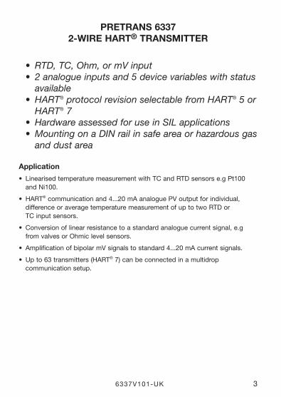
• RTD, TC, Ohm, or mV input • 2 analogue inputs and 5 device variables with status available • HART® protocol revision selectable from HART® 5 or HART® 7 • Hardware assessed for use in SIL applications • Mounting on a DIN rail in safe area or hazardous gas and dust area
Application
• LinearisedtemperaturemeasurementwithTCandRTDsensorse.gPt100and Ni100.
• HART® communication and 4...20 mA analogue PV output for individual, difference or average temperature measurement of up to two RTD or TC input sensors.
• Conversionoflinearresistancetoastandardanaloguecurrentsignal,e.gfrom valves or Ohmic level sensors.
• AmplificationofbipolarmVsignalstostandard4...20mAcurrentsignals.
• Upto63transmitters(HART® 7) can be connected in a multidrop communication setup.
4 6337V101-UK
Technical characteristics
• HART® protocol revision can be changed by user configuration to either HART® 5 or HART® 7 protocol.
• TheHART® 7 protocol offers: ∙ Long Tag numbers of up to 32 characters.
∙ Enhanced Burst Mode and Event notification with time stamping.
∙ Device variable and status mapping to any dynamic variable PV, SV, TV or QV.
∙ Process signal trend measurement with logs and summary data.
∙ Automatic event notification with time stamps.
∙ Command aggregation for higher communication efficiency.
• 6337isdesignedaccordingtostrictsafetyrequirementsandisthereforesuitable for applications in SIL installations.
• Continuouscheckofvitalstoreddata.
• MeetingtheNAMURNE21recommendations,the6337HARTtransmitterensures top measurement performance in harsh EMC environments. Additionally, the 6337 meets NAMUR NE43 and NE89 recommendations.
Mounting / installation / programming
• DINrailmountingwithupto84channelspermetre.
• ConfigurationviastandardHART® communication interfaces or by PR 5909 Loop Link.
• NB:AsExbarrierfor6337Dwerecommend5106Band9106B.
6337V101-UK 5
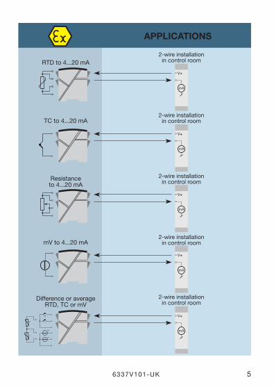
APPlICATIoNS
V+
mA
V+
mA
V+
mA
V+
mA
V+
mA
12
2
12
1
RTD to 4...20 mA
TC to 4...20 mA
Resistanceto 4...20 mA
Difference or averageRTD, TC or mV
2-wire installationin control room
2-wire installationin control room
2-wire installationin control room
2-wire installationin control room
mV to 4...20 mA2-wire installationin control room
6 6337V101-UK
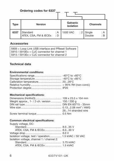
Technical data
Environmental conditions:Specifications range .................................... -40°C to +60°C Storage temperature ................................... -40°C to +85°C Calibration temperature............................... 20...28°C Relative humidity .........................................<95%RH(noncond.)Protection degree ........................................ IP20
Mechanical specifications:Dimensions(HxWxD) ................................... 109 x 23.5 x 104 mm Weightapprox.,1/2ch.version .............. 150 / 200 gDIN rail type ................................................. DIN EN 60715 - 35mmWiresize ...................................................... 0.13...2.08 mm2/AWG 26...14 stranded wireScrew terminal torque ................................. 0.5 Nm
Common electrical specifications:Supply voltage, DC: Standard............................................... 8.0...35 V ATEX, CSA, FM & IECEx ...................... 8.0...30 V Voltage drop ................................................ 8.0 VIsolation voltage, test / operation................ 1.5 kVAC / 50 VACIsolation voltage, channel 1 / channel 2: Standard............................................... 3.75 kVAC ATEX, CSA, FM & IECEx ...................... 1.5 kVAC
ordering codes for 6337
5909 = Loop Link USB interface and PReset Software5910 / 5910Ex = CJC connector for channel 15913 / 5913Ex = CJC connector for channel 2
Accessories
Type Version Galvanic isolation Channels
6337 Standard : A ATEX, CSA, FM & IECEx : D
1500 VAC : 2 Single : A Double : B

6337V101-UK 7
Signal / noise ratio ...................................... > 60 dBCommunications interface .......................... Loop Link & HART® Responsetime(programmable).. ................ 1...60 s Accuracy, the greater of general and basic values:
TC B1 accuracy specification range .......... > 400°C TC B2 accuracy specification range .......... > 160°C < 400°C
TC B3 accuracy specification range ......... > 85°C < 160°C
TC B4 accuracy specification range ......... < 85°C
TC cold junction compensation .................. < ±1.0°C Max. offset on input signal .......................... 50% of selec. max. value
Basic values
Input type
Basic accuracy
Temperature coefficient
Pt50 - Pt1000 ≤ ±0.1°C ≤ ±0.005°C/°C
Ni50 - Ni1000 ≤ ±0.2°C ≤ ±0.005°C/°C
Lin. R ≤ ±0.1 Ω ≤±5mW/°C
Volt ≤ ±10 µV ≤ ±0.5 µV / °C
TC type: E, J, K, L, N, T, U
≤ ±0.5°C
≤ ±0.025°C / °C
TC type: B1,Lr,R,S,W3,W5
≤ ±1°C
≤ ±0.1°C / °C
TC type:B2 ≤ ±3°C ≤ ±0.3°C / °C
TC type:B3 ≤ ±8°C ≤ ±0.8°C / °C
TC type:B4 not specified not specified
General values
Input type
Absolute accuracy
Temperature coefficient
All ≤ ±0.05% of span ≤ ±0.005% of span / °C
EMC immunity influence ..................................... < ±0.1% of spanExtended EMC immunity:NAMUR NE 21, A criterion, burst ....................... < ±1% of span
8 6337V101-UK
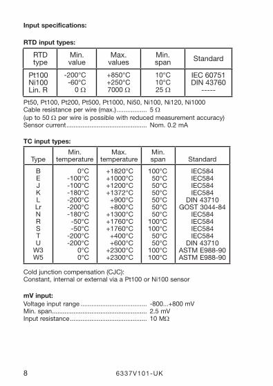
Input specifications:
RTD input types:
Pt50, Pt100, Pt200, Pt500, Pt1000, Ni50, Ni100, Ni120, Ni1000Cableresistanceperwire(max.) ................. 5 Ω(upto50Ω per wire is possible with reduced measurement accuracy)Sensor current ............................................. Nom. 0.2 mA
TC input types:
Coldjunctioncompensation(CJC):Constant, internal or external via a Pt100 or Ni100 sensor
mV input:Voltage input range ..................................... -800...+800 mV Min. span ..................................................... 2.5 mV Input resistance ........................................... 10 MΩ
RTD type
Min. value
Max. values
Min. span Standard
Pt100 Ni100 Lin. R
-200°C -60°C
0 Ω
+850°C +250°C 7000 Ω
10°C 10°C 25 Ω
IEC 60751 DIN 43760
-----
Type
Min. temperature
Max. temperature
Min. span
Standard
B E J K L Lr N R S T U W3 W5
0°C -100°C -100°C -180°C -200°C -200°C -180°C -50°C -50°C
-200°C -200°C
0°C 0°C
+1820°C +1000°C +1200°C +1372°C +900°C +800°C
+1300°C +1760°C +1760°C +400°C +600°C
+2300°C +2300°C
100°C 50°C 50°C 50°C 50°C 50°C 50°C
100°C 100°C 50°C 50°C
100°C 100°C
IEC584 IEC584 IEC584 IEC584
DIN 43710 GOST 3044-84
IEC584 IEC584 IEC584 IEC584
DIN 43710 ASTM E988-90 ASTM E988-90
6337V101-UK 9
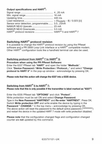
output specifications and HART®:Signal range ................................................ 4...20 mA Min. signal range ......................................... 16 mA Updating time .............................................. 440 ms Load resistance ........................................... ≤(Vsupply - 8) / 0.023 [Ω] Sensor error detection, programmable ....... 3.5...23mANAMUR NE43 Upscale ............................... 23 mA NAMUR NE43 Downscale ........................... 3.5 mAHART® protocol revisions ........................... HART® 5 and HART® 7
Switching HART® protocol revisionIt is possible to change the HART® protocol revision by using the PReset software and a PR 5909 Loop Link interface or a HART® compatible modem.Other HART® configuration tools like a handheld terminal can also be used.
Switching protocol from HART® 7 to HART® 5:Procedure when using the PR PReset Software:Enter the 6337 PReset tab ”HART” and open the folder ”Methods”.Click ”Device Password / Write Protection / Protocol...” and select ”Change protocol to HART 5” in the pop-up window - acknowledge by pressing OK.
Please note that this action will change the 6337 into a 6335 device.
Switching from HART® 5 to HART® 7:Please note that this is only possible if the transmitter is label marked as ”6337”!
Enter the 6335 PReset tab ”oPTIoNS” and click ”Protect”.WriteprotectionmustbesetONandselectChange Password. Type in the New Password ”HARTREV7” and Re-enter ”HARTREV7”. Press OK.Switch Write protection oFF and write enable the device by typing in the Password ”-CHANGE-” in the top menu - acknowledge by pressing OK.Theaboveactionwillresetthepasswordtothedefaultactivepassword(”********”) and restart the device in the updated HART 7 mode with write protection disabled.
Please note that the configuration changed flags and configuration changed counter are not updated by this command.
10 6337V101-UK
Approvals:EMC 2004/108/EC ...................................... EN 61326-1GOST R
Ex / I.S.:6337A: ATEX 94/9/EC....................................... KEMA 10ATEX0006 X IECEx ................................................... KEM 10.0084 X6337D: ATEX 94/9/EC....................................... KEMA 09ATEX0148 IECEx ................................................... KEM 10.0083 X FM certificate ....................................... 2D5A7 CSA certificate ..................................... 1125003 GOST Ex
Functional Safety:Hardware assessed for use in SIL applicationsFMEDA report - www.prelectronics.com
6337V101-UK 11
51 52 54 53 51 52 54 53 51 52 54 53
41 42 44 43 42 44 43 41 41 42 44 43
41 42 44 43
+ -
41 42 44 43 41 42 44 43 41 42 44 43
51 52 54 53
+ -
51 52 54 53 51 52 54 53 51 52 54 53
51 54 CJC 52
41 42 44 CJC
+ -
+ -
Ch
ann
el 1
C
han
nel
2
Ch
ann
el 2
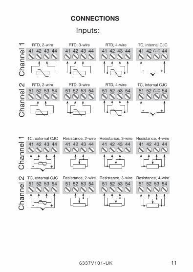
Inputs:
Ch
ann
el 1
RTD, 2-wire RTD, 3-wire RTD, 4-wire TC, internal CJC
TC, internal CJC RTD, 2-wire RTD, 3-wire RTD, 4-wire
Resistance, 2-wire Resistance, 3-wire Resistance, 4-wire TC, external CJC
Resistance, 2-wire Resistance, 3-wire Resistance, 4-wire TC, external CJC
CoNNECTIoNS
12 6337V101-UK
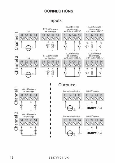
CoNNECTIoNS
41 42 4443 11 12 1413 11 12 1413
51 52 5453 21 22 2423 21 22 2423
+
-
1+
-
2
+
-
1+
-
2
+mA
+mA
51 52 54CJC
+
-1
+
-2
51 52 5453
+
-1
+
-2
41 42 4443
+-
51 52 5453
+-
41 42 4443
12
51 52 5453
12
41 42 44
+
-1
+
-2
41 42 4443
+
-1
+
-2
CJC
Outputs:
Chan
nel 2
Inputs:Ch
anne
l 1
mV
mV
Cha
nnel
1C
hann
el 2
2-wire installation
2-wire installation
TC, dierenceor average,
with internal CJC
TC, dierenceor average,
with internal CJC
TC, dierenceor average,
with external CJC
TC, dierenceor average,
with external CJC
mV, dierenceor average
mV, dierenceor average
RTD, dierenceor average
RTD, dierenceor average
HART® comm.
HART® comm.
6337V101-UK 13
0...
16
mA
43
2
*
44
14 13 1112
43 42 41 5354 5152
2324 22 21
+ -m
V
mA
MU
X
4 m
A
PG
A
D /
A
A /
D
CH
1
CH
2
+ -
CPU
EE
PR
OM
6337
6337
Sup
ply
-
4...2
0 m
A
TCm
VR
TD, l
in. R
- wir
e
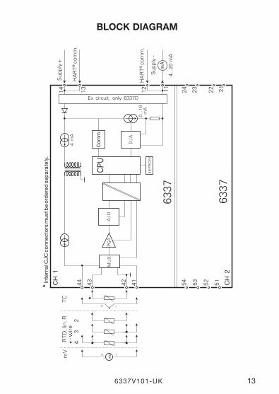
Ex circuit, only 6337D
* Int
erna
l CJC
co
nnec
tors
mus
t be
ord
ered
sep
arat
ely.
Su
pp
ly +
HA
RT
® c
om
m.
HA
RT
® c
om
m.
Com
m.
BloCK DIAGRAM
14 6337V101-UK
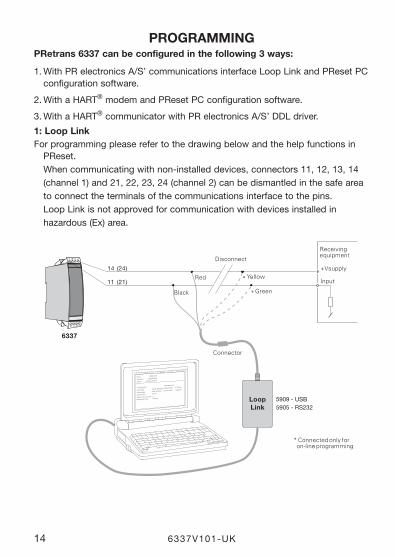
PRoGRAMMINGPRetrans 6337 can be configured in the following 3 ways:
1.WithPRelectronicsA/S’communicationsinterfaceLoopLinkandPResetPCconfiguration software.
2.WithaHART® modem and PReset PC configuration software.
3.WithaHART® communicator with PR electronics A/S’ DDL driver.
1: loop linkFor programming please refer to the drawing below and the help functions in
PReset. Whencommunicatingwithnoninstalleddevices,connectors11,12,13,14(channel1)and21,22,23,24(channel2)canbedismantledinthesafeareato connect the terminals of the communications interface to the pins. Loop Link is not approved for communication with devices installed in hazardous(Ex)area.
6337
*
*
4 443424151
1211 12 13 14
14 (24)
11 (21)
File Product Input Output Communication Language Option 08:30:00
PRetop 5331
Date: 2004-8-10
043201594
PRelectronics
Analog inputAnalog output
Serial no:
Input type:Output type: 4 - 20mA
UpscaleSensor error:
Pt100 DIN/IEC
0.00 - 50.00 C
3-wire
1.00 sec------
Input range:
Connection:
Cold junction comp:
Response time:
Tag no:
LoopLink
5909 - USB5905 - RS232
Disconnect
+Vsupply
* Connected only for on-line programming
Black
Red Yellow
Green
Input
Receivingequipment
Connector

6337V101-UK 15
1 3 ( 2 3 )
1 2 ( 2 2 )
F i l e P r o d u c t I n p u t O u t p u t C o m m u n i c a t i o n L a n g u a g e O p t i o n 0 8 : 3 0 : 0 0
P R e t o p 5 3 3 1
D a t e : 1 9 9 4 - 8 - 1 0
9 4 3 2 0 1 5 9 4
P R e l e c t r o n i c s
A n a l o g i n p u t A n a l o g o u t p u t
S e r i a l n o :
I n p u t t y p e : O u t p u t t y p e : 4 - 2 0 m A
U p s c a l e S e n s o r e r r o r : P t 1 0 0 D I N / I E C
0 . 0 0 - 5 0 . 0 0 C
3 - w i r e
1 . 0 0 s e c - - - - - -
I n p u t r a n g e :
C o n n e c t i o n :
C o l d j u n c t i o n c o m p :
R e s p o n s e t i m e :
T a g n o :
4 4 4 3 4 2 4 1 5 1
1 2 1 1 1 2 1 3 1 4
6337
+Vsupply
Input
Receiving equipment
Rload > 250 Ω, < 1100 Ω
HART® modem
4 4 4 3 4 2 4 1 5 1
1 2 1 1 1 2 1 3 1 4
1 3 ( 2 3 )
1 2 ( 2 2 )
6337
Safe area
+Vsupply
Input
Receiving equipment area
Rload > 250 Ω, < 1100 Ω
12 (22)
2: HART® modemFor programming please refer to the drawing below and the help functions in
PReset.
3: HART® communicator
For programming please refer to the drawing below. To get access to product-specific commands, the HART® communicator must be loaded with the PR electronics A/S DDL driver. This can be ordered either at the HART® Communica tion Foundation or PR electronics A/S.
16 6337V101-UK
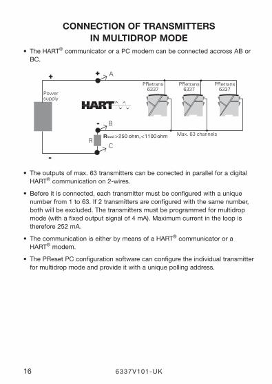
CoNNECTIoN oF TRANSMITTERS IN MUlTIDRoP MoDE
• TheHART® communicator or a PC modem can be connected accross AB or BC.
• Theoutputsofmax.63transmitterscanbeconectedinparallelforadigitalHART® communication on 2-wires.
• Beforeitisconnected,eachtransmittermustbeconfiguredwithauniquenumber from 1 to 63. If 2 transmitters are configured with the same number, both will be excluded. The transmitters must be programmed for multidrop mode(withafixedoutputsignalof4mA).Maximumcurrentintheloopistherefore 252 mA.
• ThecommunicationiseitherbymeansofaHART® communicator or a HART® modem.
• ThePResetPCconfigurationsoftwarecanconfiguretheindividualtransmitterfor multidrop mode and provide it with a unique polling address.
R
A
B
C
PRetrans6337
PRetrans6337
PRetrans6337
+
-
+
-
Powersupply
Rload > 250 ohm, < 1100 ohm Max. 63 channels
APPENDIX
ATEX INSTAllATIoN DRAWING - 6337A
IECEX INSTAllATIoN DRAWING - 6337A
ATEX INSTAllATIoN DRAWING - 6337D
IECEX INSTAllATIoN DRAWING - 6337D
FM INSTAllATIoN DRAWING No. 6335QF01
CSA INSTAllATIoN DRAWING No. 6335QC02
6337V101-UK 17
18 6337V101-UK
6335QA02LERBAKKEN 10, 8410 RØNDE DENMARK. WWW.PRELECTRONICS.COM
Revision date:
2011-02-01 Version Revision
V3R0 Page:
1/2
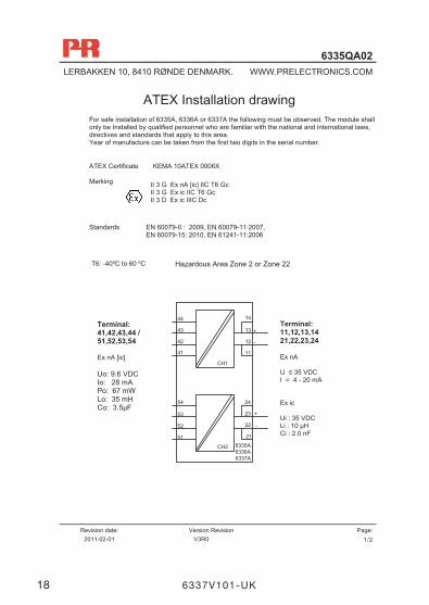
ATEX Installation drawing For safe installation of 6335A, 6336A or 6337A the following must be observed. The module shall only be Installed by qualified personnel who are familiar with the national and international laws, directives and standards that apply to this area. Year of manufacture can be taken from the first two digits in the serial number.
ATEX Certificate KEMA 10ATEX 0006X Marking
Standards EN 60079-0 : 2009, EN 60079-11:2007,
EN 60079-15: 2010, EN 61241-11:2006
II 3 G Ex nA [ic] IIC T6 Gc II 3 G Ex ic IIC T6 Gc II 3 D Ex ic IIIC Dc
Hazardous Area Zone 2 or Zone 22 T6: -40ºC to 60 ºC
Terminal: 41,42,43,44 / 51,52,53,54 Ex nA [ic] Uo: 9.6 VDC Io: 28 mA Po: 67 mW Lo: 35 mH Co: 3.5μF
Terminal: 11,12,13,14 21,22,23,24 Ex nA U ≤ 35 VDC I = 4 - 20 mA Ex ic Ui : 35 VDC Li : 10 μH Ci : 2.0 nF
13
12
44
43
42
41
+
-
23
22
54
53
52
51
+
-
6335A6336A6337A
CH2
CH1
21
24
14
11
6337V101-UK 19
6335QA02LERBAKKEN 10, 8410 RØNDE DENMARK. WWW.PRELECTRONICS.COM
Revision date:
2011-02-01 Version Revision
V3R0 Page:
2/2
Special conditions for safe use.
Type of protection Ex ic IIC Gc: The transmitter shall be installed in an enclosure that provides a degree of protection of at least IP54 according to EN60529. Type of protection Ex ic IIIC Dc: The transmitter shall be installed in an enclosure providing a degree of protection of at least IP6X according to EN60529. The surface temperature of the enclosure is equal to the ambient temperature +20 K, for a dust layer with a maximum thickness of 5 mm.
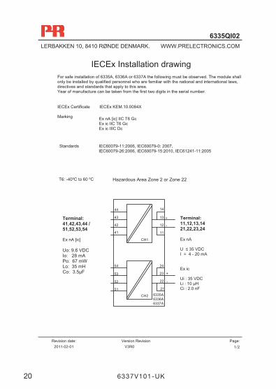
6335QI02LERBAKKEN 10, 8410 RØNDE DENMARK. WWW.PRELECTRONICS.COM
Revision date:
2011-02-01 Version Revision
V3R0 Page:
1/2
IECEx Installation drawing For safe installation of 6335A, 6336A or 6337A the following must be observed. The module shall only be installed by qualified personnel who are familiar with the national and international laws, directives and standards that apply to this area. Year of manufacture can be taken from the first two digits in the serial number.
IECEx Certificate IECEx KEM.10.0084X Marking
Standards IEC60079-11:2006, IEC60079-0: 2007, IEC60079-26:2006, IEC60079-15:2010, IEC61241-11:2005
Ex nA [ic] IIC T6 Gc Ex ic IIC T6 Gc Ex ic IIIC Dc
Hazardous Area Zone 2 or Zone 22 T6: -40ºC to 60 ºC
Terminal: 41,42,43,44 / 51,52,53,54 Ex nA [ic] Uo: 9.6 VDC Io: 28 mA Po: 67 mW Lo: 35 mH Co: 3.5μF
Terminal: 11,12,13,14 21,22,23,24 Ex nA U ≤ 35 VDC I = 4 - 20 mA Ex ic Ui : 35 VDC Li : 10 μH Ci : 2.0 nF
13
12
44
43
42
41
+
-
23
22
54
53
52
51
+
-
6335A6336A6337A
CH2
CH1
21
24
14
11
20 6337V101-UK
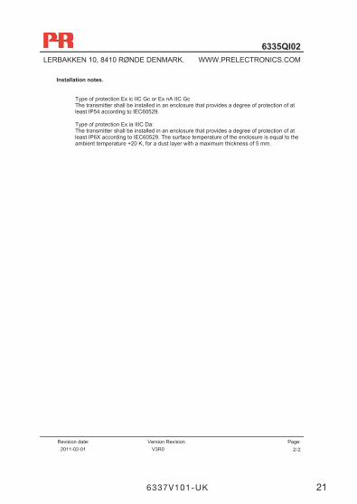
6335QI02LERBAKKEN 10, 8410 RØNDE DENMARK. WWW.PRELECTRONICS.COM
Revision date:
2011-02-01 Version Revision
V3R0 Page:
2/2
Installation notes.
Type of protection Ex ic IIC Gc or Ex nA IIC Gc The transmitter shall be installed in an enclosure that provides a degree of protection of at least IP54 according to IEC60529. Type of protection Ex ia IIIC Da: The transmitter shall be installed in an enclosure that provides a degree of protection of at least IP6X according to IEC60529. The surface temperature of the enclosure is equal to the ambient temperature +20 K, for a dust layer with a maximum thickness of 5 mm.
6337V101-UK 21
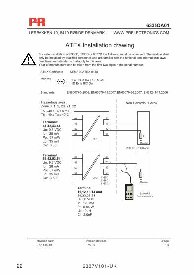
6335QA01LERBAKKEN 10, 8410 RØNDE DENMARK. WWW.PRELECTRONICS.COM
Revision date:
2011-02-01 Version Revision
V3R0 0Page:
1/2
ATEX Installation drawing For safe installation of 6335D, 6336D or 6337D the following must be observed. The module shall only be Installed by qualified personnel who are familiar with the national and international laws, directives and standards that apply to this area. Year of manufacture can be taken from the first two digits in the serial number.
ATEX Certificate KEMA 09ATEX 0148 Marking
Standards EN60079-0:2009, EN60079-11:2007, EN60079-26:2007, EN61241-11:2006
Non Hazardous Area Hazardous area Zone 0, 1, 2, 20, 21, 22
II 1 G Ex ia IIC T6..T5 Ga II 1D Ex ia IIIC Da
Terminal: 41,42,43,44 Uo: 9.6 VDC Io: 28 mA Po: 67 mW Lo: 35 mH Co: 3.5μF
Terminal: 11,12,13,14 and 21,22,23,24 Ui: 30 VDC Ii: 120 mA Pi: 0.84 W Li: 10μH Ci: 2.0nF
T5: -40 ≤ Ta ≤ 60ºC T6: -40 ≤ Ta ≤ 40ºC
Terminal: 51,52,53,54 Uo: 9.6 VDC Io: 28 mA Po: 67 mW Lo: 35 mH Co: 3.5μF
13
12
44
43
42
41
+
-
Barrier
23
22
54
53
52
51
+
-
Barrier
6335D6336D6337D
CH2
CH1
21
24
14
11
Ex HARTCommunicator
R
R
250 < R < 1100 ohm
22 6337V101-UK
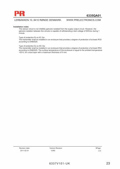
6335QA01LERBAKKEN 10, 8410 RØNDE DENMARK. WWW.PRELECTRONICS.COM
Revision date:
2011-02-01 Version Revision
V3R0 0Page:
2/2
Installation notes The sensor circuit is not infallibly galvanic isolated from the supply output circuit. However, the galvanic isolation between the circuits is capable of withstanding a test voltage of 500Vac during 1 minute. Type of protection Ex ia IIC Ga: The transmitter shall be installed in an enclosure that provides a degree of protection of at least IP20 according to EN60529. Type of protection Ex ia IIIC Da: The transmitter shall be installed in an enclosure that provides a degree of protection of at least IP6X according to EN60529. The surface temperature of the enclosure is equal to the ambient temperature +20 K, for a dust layer with a maximum thickness of 5 mm.
6337V101-UK 23
6335QI01LERBAKKEN 10, 8410 RØNDE DENMARK. WWW.PRELECTRONICS.COM
Revision date:
2011-02-01 Version Revision
V3R0 0Page:
1/2
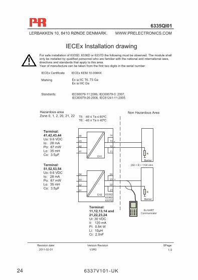
IECEx Installation drawing For safe installation of 6335D, 6336D or 6337D the following must be observed. The module shall only be installed by qualified personnel who are familiar with the national and international laws, directives and standards that apply to this area. Year of manufacture can be taken from the first two digits in the serial number.
IECEx Certificate IECEx KEM.10.0084X Marking
Standards: IEC60079-11:2006, IEC60079-0: 2007,
IEC60079-26:2006, IEC61241-11:2005
Non Hazardous Area Hazardous area Zone 0, 1, 2, 20, 21, 22
Ex ia IIC T6..T5 Ga Ex ia IIIC Da
Terminal: 41,42,43,44 Uo: 9.6 VDC Io: 28 mA Po: 67 mW Lo: 35 mH Co: 3.5μF
Terminal: 11,12,13,14 and 21,22,23,24 Ui: 30 VDC Ii: 120 mA Pi: 0.84 W Li: 10μH Ci: 2.0nF
Terminal: 51,52,53,54 Uo: 9.6 VDC Io: 28 mA Po: 67 mW Lo: 35 mH Co: 3.5μF
13
12
44
43
42
41
+
-
Barrier
23
22
54
53
52
51
+
-
Barrier
6335D6336D6337D
CH2
CH1
21
24
14
11
Ex HARTCommunicator
R
R
250 < R < 1100 ohm
T5: -40 ≤ Ta ≤ 60ºC T6: -40 ≤ Ta ≤ 40ºC
24 6337V101-UK
6335QI01LERBAKKEN 10, 8410 RØNDE DENMARK. WWW.PRELECTRONICS.COM
Revision date:
2011-02-01 Version Revision
V3R0 0Page:
2/2
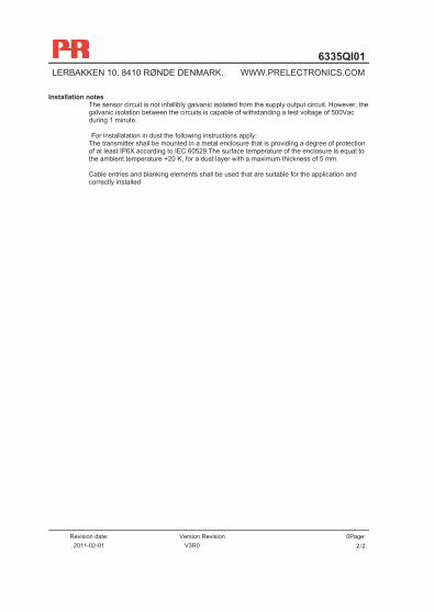
Installation notes The sensor circuit is not infallibly galvanic isolated from the supply output circuit. However, the galvanic isolation between the circuits is capable of withstanding a test voltage of 500Vac during 1 minute.
For installalation in dust the following instructions apply:
The transmitter shall be mounted in a metal enclosure that is providing a degree of protection of at least IP6X according to IEC 60529.The surface temperature of the enclosure is equal to the ambient temperature +20 K, for a dust layer with a maximum thickness of 5 mm. Cable entries and blanking elements shall be used that are suitable for the application and correctly installed

6335QF01LERBAKKEN 10, 8410 RØNDE DENMARK. WWW.PRELECTRONICS.COM
Revision date:
2011-02-02 Version Revision
V3R0 Page:
1/1
FM Installation drawing
Installation notes. For installation in Class I the Transmitter must be installed in a suitable enclosure to meet installation codes stipulated in The National Electrical Code (ANSI-NFPA 70). Equipment that is FM-approved for intrinsic safety may be connected to barriers based on the Entity Concept. This concept permits interconnection of approved transmitters, meters and other devices in combinations, which have not been specifically examined by FM, provided that the agency's criteria are met. The combination is then intrinsically safe, if the entity concept is acceptable to the authority having jurisdiction over the installation. The entity concept criteria are as follows: The intrinsically safe devices, other than barriers, must not be a source of power. The maximum voltage Ui(VMAX) and current Ii(IMAX), and maximum power Pi(Pmax), which the device can receive and remain intrinsically safe, must be equal to or greater than the voltage (Uo or VOC or Vt) and current (Io or ISC or It) and the power Po which can be delivered by the barrier. The sum of the maximum unprotected capacitance (Ci) for each intrinsically device and the interconnecting wiring must be less than the capacitance (Ca) which can be safely connected to the barrier. The sum of the maximum unprotected inductance (Li) for each intrinsically device and the interconnecting wiring must be less than the inductance (La) which can be safely connected to the barrier. The entity parameters Uo, VOC or Vt and Io, ISC or It, and Ca and La for barriers are provided by the barrier manufacturer.
Non Hazardous Location Hazardous (Classified ) Location Class I, Division 1, Group A,B,C,D Class I, Zone 0, IIC
Terminal: 41,42,43,44 Uo: 9.6 VDC Io: 28 mA Po: 67 mW Lo: 35 mH Co: 3.5μF
Terminal: 11,12,13,14 and 21,22,23,24 Ui: 30 VDC Ii: 120 mA Pi: 0.84 W Li: 10μH Ci: 2.0nF
T6: -40 ≤ Ta ≤ 60ºC
Terminal: 51,52,53,54 Uo: 9.6 VDC Io: 28 mA Po: 67 mW Lo: 35 mH Co: 3.5μF
13
12
44
43
42
41
+
-
Barrier
23
22
54
53
52
51
+
-
Barrier6335D6336D6337D
CH2
CH1
21
24
14
11
Ex HARTCommunicator
R
R
250 < R < 1100 ohm

6335QC02LERBAKKEN 10, 8410 RØNDE DENMARK. WWW.PRELECTRONICS.COM
Revision date:
2011-03-10 Version Revision
V3R0 Page:
1/1
CSA Installation drawing
Installation notes. The Transmitter must be installed in a suitable enclosure to meet installation codes stipulated in The Canadian Electrical Code (CEC). Channel 1 and Channel 2 are separate channels and therefore separate shielded cables shall be used for each channel. Substitution of components may impair intrinsic safety.
Non Hazardous Location Hazardous (Classified ) Location Class I, Division 1, Group A,B,C,D Class I, Zone 0, IIC
Terminal: 41,42,43,44 Uo: 9.6 VDC Io: 28 mA Po: 67 mW Lo: 35 mH Co: 3.5μF
Terminal: 11,12,13,14 and 21,22,23,24 Ui: 30 VDC Ii: 120 mA Pi: 0.84 W Li: 10μH Ci: 2.0nF Co(Ca) > ∑(Ci+Ccable) Lo(La) > ∑ (Li+Lcable)
T6: -40 ≤ Ta ≤ 60ºC
Terminal: 51,52,53,54 Uo: 9.6 VDC Io: 28 mA Po: 67 mW Lo: 35 mH Co: 3.5μF
13
12
44
43
42
41
+
-
Barrier
23
22
54
53
52
51
+
-
Barrier6335D6336D6337D
CH2
CH1
21
24
14
11
Ex HARTCommunicator
R
R
250 < R < 1100 ohm
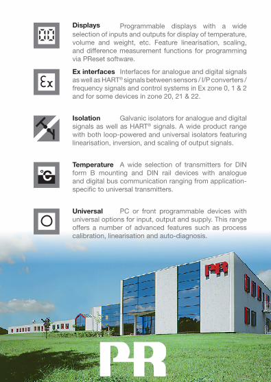
Programmable displays with a wide selection of inputs and outputs for display of temperature, volume and weight, etc. Feature linearisation, scaling, and difference measurement functions for programming via PReset software.
Displays
A wide selection of transmitters for DIN form B mounting and DIN rail devices with analogue and digital bus communication ranging from application- specific to universal transmitters.
Temperature
Galvanic isolators for analogue and digital signals as well as HART® signals. A wide product range with both loop-powered and universal isolators featuring linearisation, inversion, and scaling of output signals.
Isolation
Interfaces for analogue and digital signals as well as HART® signals between sensors / I/P converters / frequency signals and control systems in Ex zone 0, 1 & 2 and for some devices in zone 20, 21 & 22.
Ex interfaces
PC or front programmable devices with universal options for input, output and supply. This range offers a number of advanced features such as process calibration, linearisation and auto-diagnosis.
Universal

Head officeDenmark www.prelectronics.comPR electronics A/S [email protected] 10 tel. +45 86 37 26 77DK-8410 Rønde fax +45 86 37 30 85
www.prelectronics.fr [email protected]
www.prelectronics.de [email protected]
www.prelectronics.es [email protected]
www.prelectronics.it [email protected]
www.prelectronics.se [email protected]
www.prelectronics.co.uk [email protected]
www.prelectronics.com [email protected]
www.prelectronics.cn [email protected]


![Maximum and coupling of the sine-Gordon fieldTheorem 1.2 provides an analogue for the (non-Gaussian) sine-Gordon field of results of [36] for Gaussian log-correlated fields. In](https://img.pdfslide.tips/doc/110x75/607624e4c7f0fd7c67500dfe/maximum-and-coupling-of-the-sine-gordon-ield-theorem-12-provides-an-analogue.jpg)


![arXiv:math/0612545v1 [math.RT] 19 Dec 2006 · arXiv:math/0612545v1 [math.RT] 19 Dec 2006 AN ANALOGUE OF THE CARTAN DECOMPOSITION FOR p-ADIC REDUCTIVE SYMMETRIC SPACES by …](https://img.pdfslide.tips/doc/110x75/5b9b1d7c09d3f22d2a8ca237/arxivmath0612545v1-mathrt-19-dec-2006-arxivmath0612545v1-mathrt-19.jpg)