Embed Size (px)
Citation preview

Slide 115th Topical Meeting on Silicon Monolithic Integrated Circuits in RF Systems, 2015 San Diego, CA
A 20GHz Class-C VCO
Using Noise Sensitivity
Mitigation Technique
Kento Kimura, Kenichi Okada and Akira Matsuzawa
(WE2C-2)
Matsuzawa & Okada Lab.
Tokyo Institute of Technology, Japan
Matsuzawa& Okada Lab.
Matsuzawa Lab.Tokyo Institute of Technology
Matsuzawa& Okada Lab.
Matsuzawa Lab.Tokyo Institute of Technology
Slide 215th Topical Meeting on Silicon Monolithic Integrated Circuits in RF Systems, 2015 San Diego, CA
・Background
・Class-C VCO
・PN Degradation on Class-C VCO AM-PM Conversion
Parasitic Cap Variation
・Proposed AM-PM Conversion Cancellation 𝑪𝑮𝑺 curve
𝑪𝐒𝐁 curve
・Conclusion
Outline

Slide 315th Topical Meeting on Silicon Monolithic Integrated Circuits in RF Systems, 2015 San Diego, CA
Background
[1]K. Okada, et al., ISSCC 2011
・60GHz CMOS Transceiver IC
→ Local Oscillator using Injection-Locking
Lower phase noise than direct 60GHz generation
ref.PFD CP LPF
20GHz PLL60GHz QILO
Divider
・20GHz VCO Requirement
→ 1. Quite low noise 2. High power efficiency

Slide 415th Topical Meeting on Silicon Monolithic Integrated Circuits in RF Systems, 2015 San Diego, CA
・Phase Noise Theory in LC-Tank Oscillator
VCO Performance
𝐏𝐍 = 𝟏𝟎𝐥𝐨𝐠𝟏𝟎𝑷𝐧𝐨𝐢𝐬𝐞𝑷𝐬𝐢𝐠
= 𝟏𝟎𝐥𝐨𝐠𝟏𝟎𝟐𝑭𝐤𝐁𝑻
𝑷𝐬𝐢𝐠∙ (
𝝎𝟎
𝟐𝑸𝝎𝐨𝐟𝐟𝐬𝐞𝐭)𝟐
𝐏𝐄 =𝑷𝐬𝐢𝐠
𝑷𝐃𝐂=𝑰𝐬𝐢𝐠
𝑰𝐃𝐂∙𝑽𝐬𝐢𝐠
𝑽𝐃𝐂
・Power Efficiency in LC-Tank Oscillator
→ should maximize
→ should be close to 1

Slide 515th Topical Meeting on Silicon Monolithic Integrated Circuits in RF Systems, 2015 San Diego, CA
High Spectral Purity
→ High Q-factor
Low Power Efficiency
→ Square current waveform
LC-based VCO
𝑰𝐬𝐢𝐠
𝑰𝐃𝐂=𝟐
𝛑
𝑽𝐠𝐬
𝑽𝐝𝐬

Slide 615th Topical Meeting on Silicon Monolithic Integrated Circuits in RF Systems, 2015 San Diego, CA
Class-C VCO[2]
[2] A. Mazzanti, et al., JSSC 2008
High Current Efficiency
→ Sinusoidal waveform
Tr keeps in saturation region
𝑰𝐬𝐢𝐠
𝑰𝐃𝐂= 𝟏

Slide 715th Topical Meeting on Silicon Monolithic Integrated Circuits in RF Systems, 2015 San Diego, CA
Class-C VCO[2]
𝑽𝐬𝐢𝐠 <𝑽𝐃𝐃 + 𝑽𝐓𝐇 − 𝑽𝐆𝐁𝐈𝐀𝐒
𝟐
𝑽𝐬𝐢𝐠
𝑽𝐃𝐂should be close to 1
→ Maximize 𝑽𝒔𝒊𝒈
→ smaller 𝑽𝐆𝐁𝐈𝐀𝐒→ larger Tr is necessary
for robust oscillation
Maximum Amplitude is limited
150
200
250
300
350
400
450
500
550
0.2 0.3 0.4 0.5 0.6 0.7 0.8 0.9
W [
um
]
Vgbias [V]
Slide 815th Topical Meeting on Silicon Monolithic Integrated Circuits in RF Systems, 2015 San Diego, CA
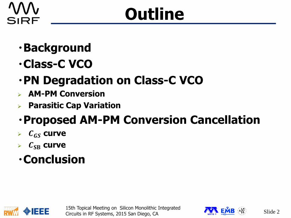
Cross-Coupled Pair
Non-Negligible Parasitic Capacitances
0
10
20
30
40
50
60
70
0 0.2 0.4 0.6 0.8 1 1.2P
ara
sit
ic C
[fF
]Vgs [V]
Cgs Cgd
Cgb Cdb
𝑪𝐆𝐒 causes random frequency variation
→ AM-PM Conversion like a varactor
𝝏𝑪𝐂𝐂𝐓𝐫𝝏𝑽𝐆𝐒
∝𝝏𝑪𝐆𝐒𝝏𝑽𝐆𝐒

Slide 915th Topical Meeting on Silicon Monolithic Integrated Circuits in RF Systems, 2015 San Diego, CA
𝑽𝐆𝐁𝐈𝐀𝐒 noise
[3] W.Deng, et al., JSSC 2013
・Noise Sources
- Resistors for DC-bias
- Adaptive Bias Circuits[3]
→ ensure robust start-up
large 𝑽𝑮𝐁𝐈𝐀𝑺 variation
∆𝒇 =𝝏𝒇
𝝏𝑽𝐆𝐁𝐈𝐀𝐒∙ ∆𝑽𝐆𝐁𝐈𝐀𝐒
Slide 1015th Topical Meeting on Silicon Monolithic Integrated Circuits in RF Systems, 2015 San Diego, CA
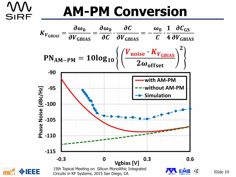
AM-PM Conversion
𝑲𝑽𝐆𝐁𝐈𝐀𝐒 =𝝏𝝎𝟎
𝝏𝑽𝐆𝐁𝐈𝐀𝐒=𝝏𝝎𝟎
𝝏𝑪∙
𝝏𝑪
𝝏𝑽𝐆𝐁𝐈𝐀𝐒= −
𝝎𝟎
𝑪∙𝟏
𝟒
𝝏𝑪𝐆𝐒𝝏𝑽𝐆𝐁𝐈𝐀𝐒
𝐏𝐍𝐀𝐌−𝐏𝐌 = 𝟏𝟎𝐥𝐨𝐠𝟏𝟎𝑽𝐧𝐨𝐢𝐬𝐞 ∙ 𝑲𝑽𝐆𝐁𝐈𝐀𝐒
𝟐𝝎𝐨𝐟𝐟𝐬𝐞𝐭
𝟐
-115
-110
-105
-100
-95
-90
-0.3 0 0.3 0.6
Ph
ase
No
ise
[d
Bc/
Hz]
Vgbias [V]
with AM-PM
without AM-PM
Simulation

Slide 1115th Topical Meeting on Silicon Monolithic Integrated Circuits in RF Systems, 2015 San Diego, CA
Design Concept
Is it possible to mitigate 𝑲𝑽𝐆𝐁𝐈𝐀𝐒 around 𝑽𝐓𝐇?
30
35
40
45
50
55
60
65
0 0.2 0.4 0.6 0.8 1 1.2
C o
f X
-Co
up
le P
air
[fF]
Vgbias [V]
Large KVgbias
Small Kvgbias
Large Variation
Small Variation

Slide 1215th Topical Meeting on Silicon Monolithic Integrated Circuits in RF Systems, 2015 San Diego, CA
Proposed Circuit
・Resistive Joint on 2 legs of Cross-Coupled Pair
Enable to Mitigate 𝑲𝑽𝐆𝐁𝐈𝐀𝐒

Slide 1315th Topical Meeting on Silicon Monolithic Integrated Circuits in RF Systems, 2015 San Diego, CA
Mechanism
Z, 𝑪𝑺𝐁 and 𝑪𝐓𝐀𝐈𝐋 have to be taken in consideration
Conventional Proposed
Shorted here

Slide 1415th Topical Meeting on Silicon Monolithic Integrated Circuits in RF Systems, 2015 San Diego, CA
Independent of ZC𝐆𝐃,C𝐃𝐁,C𝐆𝐁
Mechanism
dependent on ZC𝐆𝐒,C𝐒𝐁
C𝐆𝐒,C𝐒𝐁 contribution should be re-considered

Slide 1515th Topical Meeting on Silicon Monolithic Integrated Circuits in RF Systems, 2015 San Diego, CA
0.4
0.5
0.6
0.7
0.8
0.9
1
1 10 100 1000
Co
effi
cie
nt
Z [Ohm]
Mechanism-C𝐆𝐒
𝑪𝐆𝐒_𝐩𝐫𝐨𝐩
𝑪𝐆𝐒_𝐜𝐨𝐧𝐯= 𝟏 −
𝒈𝐦𝟐 +𝝎𝟐𝑪𝐆𝐒 ∙ (𝑪𝐆𝐒 + 𝑪𝐓𝐀𝐈𝐋)
𝟏𝒁
𝟐
+𝝎𝟐 ∙ (𝑪𝐆𝐒 + 𝑪𝐓𝐀𝐈𝐋)𝟐
𝑪𝐆𝐒 steep can be more moderate
10
20
30
40
50
60
70
0.3 0.4 0.5 0.6 0.7 0.8 0.9
Cgs
[fF
]
Vgbias [V]
R=0
R=30
R=60
R=90
Slide 1615th Topical Meeting on Silicon Monolithic Integrated Circuits in RF Systems, 2015 San Diego, CA
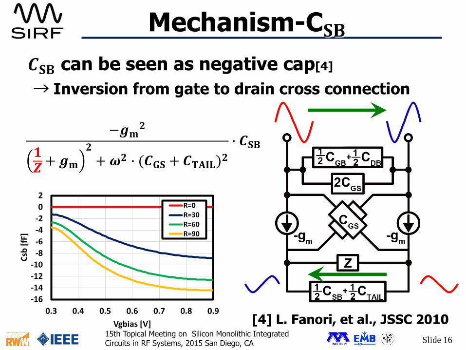
Mechanism-C𝐒𝐁
𝑪𝐒𝐁 can be seen as negative cap[4]
[4] L. Fanori, et al., JSSC 2010
→ Inversion from gate to drain cross connection
−𝒈𝐦𝟐
𝟏𝒁+ 𝒈𝐦
𝟐
+𝝎𝟐 ∙ (𝑪𝐆𝐒 + 𝑪𝐓𝐀𝐈𝐋)𝟐
∙ 𝑪𝐒𝐁
-16
-14
-12
-10
-8
-6
-4
-2
0
2
0.3 0.4 0.5 0.6 0.7 0.8 0.9
Csb
[fF
]
Vgbias [V]
R=0R=30R=60R=90

Slide 1715th Topical Meeting on Silicon Monolithic Integrated Circuits in RF Systems, 2015 San Diego, CA
Dependence to 𝑽𝐆𝐁𝐈𝐀𝐒・ Z make 𝑪𝐆𝑺 steep more moderate
・ 𝑪𝑺𝑩 generate negative steep
Frequency Sensitivity Zero point
30
32
34
36
38
40
42
44
0.3 0.4 0.5 0.6 0.7 0.8
Cro
ss-C
ou
ple
d C
apac
itan
ce [
fF]
Vgbias [V]
ConventionalR=30R=60R=90

Slide 1815th Topical Meeting on Silicon Monolithic Integrated Circuits in RF Systems, 2015 San Diego, CA
Measured Phase Noise
Phase Noise improves 3dB when Z = 60𝛀.

Slide 1915th Topical Meeting on Silicon Monolithic Integrated Circuits in RF Systems, 2015 San Diego, CA
Chip Die Photo
65nm CMOS Process
VCO Core : 0.057[𝐦𝐦𝟐]
Tail Impedance

Slide 2015th Topical Meeting on Silicon Monolithic Integrated Circuits in RF Systems, 2015 San Diego, CA
20GHz band Comparison
Ref PN@1MHz [dBc/Hz]
Freq[GHz]
Power[mW]
FoM[dBc/Hz]
Topology(LC-only)
[5] -101 26.7 21 -176.3 push-push
[6] -98 18.7 6 -176 PMOS
[7] -112 19 200 -174.5 Colpitts
[8] -106 17.9-
21.2
19.2 -179 Tail CapacitiveFeedback
ThisWork
-105.5 19.3-
22.4
8.7 -182.4 Class-C withNSM
𝐅𝐨𝐌 = 𝐏𝐍 − 𝟐𝟎 𝐥𝐨𝐠𝟏𝟎𝒇𝐜𝐞𝐧𝐭𝐞𝐫𝒇𝒐𝒇𝒇𝒔𝒆𝒕
+ 𝟏𝟎 𝐥𝐨𝐠𝟏𝟎𝑷𝐃𝐂𝟏𝐦𝐖

Slide 2115th Topical Meeting on Silicon Monolithic Integrated Circuits in RF Systems, 2015 San Diego, CA
Conclusion
– AM-PM Conversion on the cross-coupled pair can be cancelled in proposed circuit.
– It improve phase noise performance by 3dB and achieve best Figure of Merit among 20GHz Oscillators.

Slide 2215th Topical Meeting on Silicon Monolithic Integrated Circuits in RF Systems, 2015 San Diego, CA
[1] K. Okada, et al., “A 60 GHz 6QAM/8PSK/QPSK/BPSK direct-conversion transceiver for IEEE 802.15.3c,” in 2011 IEEE Int. Solid-State Circuits Conf. (ISSCC) Dig. Tech. Papers, Feb. 2011, pp. 160–162.
[2] A. Mazzanti, et al., “Class-C Harmonic CMOS VCOs, With a General Result on Phase Noise,” IEEE Journal of Solid-State Circuits, vol.43, No.12, pp.2716-2729 , Dec. 2008.
[3] W. Deng, et al., “Class-C VCO With Amplitude Feedback Loop for Robust Start-Up and Enhanced Oscillation Swing,” IEEE Journal of Solid-State Circuits, vol.48, No.2, pp.429-440 , Feb. 2013.
[4] L. Fanori, et al., “Capacitive Degeneration in LC-Tank Oscillator for DCO Fine-Frequency Tuning,” IEEE Journal of Solid-State Circuits, vol.45, no.12, pp.2737-2745, Dec. 2010.
References-1
Slide 2315th Topical Meeting on Silicon Monolithic Integrated Circuits in RF Systems, 2015 San Diego, CA
[5] R. Molave, et al., “ A 27-GHz Low-Power Push-Push LC VCO with Wide Tuning Range in 65nm CMOS,” IEEE Int. Symp. Circuits and Systems, May 2011, pp.1141-1144.
[6] G. Zhu, et al., “A Low-Power Wide-Band 20GHz VCO in 65nm CMOS,” 5th Global Symposium on Millimeter Waves, May 2012, pp.291-294.
[7] W. Wang, et al., “A 20GHz VCO and Frequency Doubler for W-band FMCW Radar Applications,” IEEE Silicon Monolithic Integrated Circuits in RF Systems, Jan. 2014, pp.104-106.
[8] A. Musa, et al., “A Low Phase Noise Quadrature Injection Locked Frequency Synthesizer for MM-Wave Applications,” IEEE Journal of Solid-State Circuits, vol.46, no.11, pp.2635-2649, Nov. 2011.
References-2
Slide 2415th Topical Meeting on Silicon Monolithic Integrated Circuits in RF Systems, 2015 San Diego, CA
This work is partially supported by MIC, SCOPE, MEXT, STARC, STAR and VDEC in collaboration with Cadence Design Systems, Inc., Mentor Graphics, Inc., and Agilent Technologies Japan, Ltd.
Acknowledgement