Embed Size (px)
Citation preview

11/22/13
1
Chapter 6 PASSBAND DATA TRANSMISSION
Dr. Samir Alghadhban
1
Content • Different methods of digital modula3on, namely, phase-‐shi8
keying, quadrature-‐ amplitude modula3on, and frequency-‐shi8 keying, and their individual variants.
• Coherent detec3on of modulated signals in addi3ve white Gaussian noise, which requires the receiver to be synchronized to the transmiCer with respect to both carrier phase and bit 3ming.
• Noncoherent detec3on of modulated signals in addi3ve white Gaussian noise, disregarding phase informa3on in the received signal
2

11/22/13
2
6.1 IntroducDon
• (a) Amplitude-‐shiI keying.
• (b) Phase-‐shiI keying.
• (c) Frequency-‐shiI keying
3
Performance Metrics
• PROBABILITY OF ERROR • POWER SPECTRA – Baseband power spectral density
• BANDWIDTH EFFICIENCY – The ra3o of the data rate in bits per second to the effec3vely u3lized channel bandwidth
ρ = RbB
bits/s/Hz
4
11/22/13
3
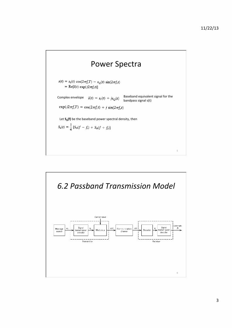
Power Spectra
Complex envelope Baseband equivalent signal for the bandpass signal s(t)
Let SB(f) be the baseband power spectral density, then
5
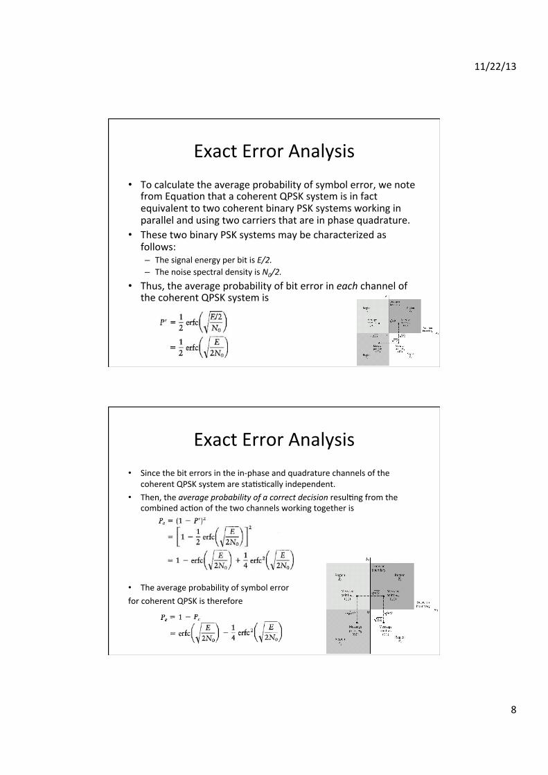
6.2 Passband Transmission Model
6

11/22/13
4
6.3 Coherent Phase-‐Shi8 Keying
7
Error Probability of BPSK Using pairwise error probability relaDon as discussed in chapter 5
Pr si → sk{ } = 1
2erfc
si − sk
2 N0
⎛
⎝⎜⎜
⎞
⎠⎟⎟= Q
si − sk
2N0
⎛
⎝⎜⎜
⎞
⎠⎟⎟
Since the Euclidean Distance between the two symbols is
s1 − s2 = d12 = 2 Eb
Pe =
12
erfcEb
No
⎛
⎝⎜
⎞
⎠⎟
8

11/22/13
5
Error Probability of BPSK Detailed Analysis
9
GeneraDon and DetecDon of Coherent BPSK Signals
(a) binary PSK transmi`er
(b) coherent binary
PSK receiver.
10

11/22/13
6
Power Spectra of BPSK Signals symbol shaping func3on
he power spectral density of a random binary wave so described is equal to the energy spectral density of the symbol shaping funcDon divided by the symbol duraDon. The energy spectral density of a Fourier transformable signal g(t) is defined as the squared magnitude of the signal's Fourier transform. (see example 1.6 in textbook)
11
QUADRIPHASE-‐SHIFT KEYING (QPSK)
12

11/22/13
7
Example of QPSK
13
(a) Input binary sequence.
(b) Odd-‐numbered bits of input sequence and associated binary PSK wave.
(c) Even-‐numbered bits of input sequence and associated binary PSK wave.
(d) QPSK waveform defined as
Error Probability of QPSK
14
Pe ≤ erfc E
2N0
⎛
⎝⎜
⎞
⎠⎟ +
12
erfc EN0
⎛
⎝⎜
⎞
⎠⎟
Using the union bound as described in chapter 5
By reducing the overlap region, a Dghter bound is
Pe ≤ erfc E
2N0
⎛
⎝⎜
⎞
⎠⎟
11/22/13
8
Exact Error Analysis • To calculate the average probability of symbol error, we note
from EquaDon that a coherent QPSK system is in fact equivalent to two coherent binary PSK systems working in parallel and using two carriers that are in phase quadrature.
• These two binary PSK systems may be characterized as follows: – The signal energy per bit is E/2. – The noise spectral density is N0/2.
• Thus, the average probability of bit error in each channel of the coherent QPSK system is
15 !
Exact Error Analysis • Since the bit errors in the in-‐phase and quadrature channels of the
coherent QPSK system are staDsDcally independent. • Then, the average probability of a correct decision resulDng from the
combined acDon of the two channels working together is
• The average probability of symbol error for coherent QPSK is therefore
16
!
11/22/13
9
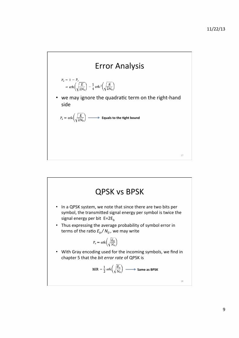
Error Analysis
• we may ignore the quadraDc term on the right-‐hand side
17
Equals to the 1ght bound
QPSK vs BPSK • In a QPSK system, we note that since there are two bits per
symbol, the transmi`ed signal energy per symbol is twice the signal energy per bit E=2Eb
• Thus expressing the average probability of symbol error in terms of the raDo Eb / N0 , we may write
• With Gray encoding used for the incoming symbols, we find in chapter 5 that the bit error rate of QPSK is
18
Same as BPSK

11/22/13
10
GeneraDon and DetecDon of Coherent QPSK Signals
19
(a) QPSK transmi`er
(b) coherent
QPSK receiver.
Power Spectra of QPSK Signals
20
the symbol shaping funcDon
Hence, the in-‐phase and quadrature components have a common power spectral density, namely, E sinc2(T/f)
The in-‐phase and quadrature components are staDsDcally independent. Accordingly, the baseband power spectral density of the QPSK signal equals the sum of the individual power spectral densiDes of the in-‐phase and quadrature components
11/22/13
11
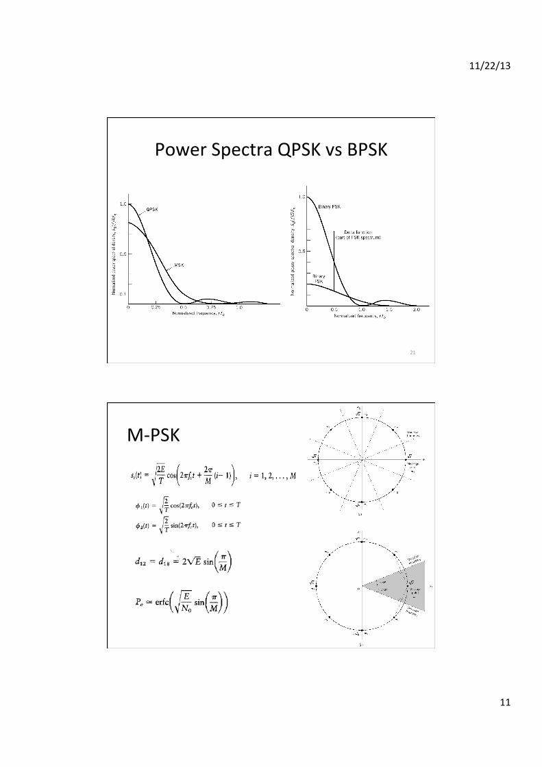
Power Spectra QPSK vs BPSK
21
M-‐PSK
22

11/22/13
12
M-‐PSK
23
M=32
M=16 M=8 M=4 M=2
Power Spectral of M-‐PSK • The symbol duraDon of M-‐ary PSK is defined by T=Tb log2 M where Tb is
the bit duraDon. • Proceeding in a manner similar to that described for a QPSK
signal, we may show that the baseband power spectral density of an M-‐ary PSK signal is given by SB(f) = 2E sinc2(Tf) = 2Eb log2 M sinc2(Tbf log2 M)
24

11/22/13
13
BANDWIDTH EFFICIENCY OF M-‐ARY PSK SIGNALS
• The power spectra of M-‐ary PSK signals possess a main lobe bounded by well-‐defined spectral nulls (i.e., frequencies at which the power spectral density is zero).
• Accordingly the spectral width of the main lobe provides a simple and popular measure for the band width of M-‐ary PSK signals.
• This definiDon is referred to as the null-‐to-‐null bandwidth.
• With the null-‐to-‐null bandwidth encompassing the main lobe of the power spectrum of an M-‐ary signal, we find that it contains most of the signal power. 25
BANDWIDTH EFFICIENCY OF M-‐ARY PSK SIGNALS
• The channel bandwidth required to pass M-‐ary PSK signals (more precisely, the main spectral lobe of M-‐ary signals)
• Where T is the symbol duraDon. Recall that T=Tblog2M • Since the bit rate Rb=1/Tb , then we have
• Therefore, the bandwidth efficiency of M-‐ary PSK signals will be:
26

11/22/13
14
BANDWIDTH EFFICIENCY OF M-‐ARY PSK SIGNALS
27
6.5 Coherent Frequency-‐ShiI Keying
28
BINARY FSK
we observe directly that the signals s1(t) and s2(t) are orthogonal, but not normalized to have unit energy. We therefore deduce that the most useful form for the set of orthonormal basis funcDons is

11/22/13
15
6.5 Coherent Frequency-‐ShiI Keying
29
BINARY FSK
30
6.5 Pairwise Error Probability: Binary FSK
• The signal constellaDon for binary FSK is:
d12 = s1 − s2 = 2Eb
E is the average signal Energy
The Euclidean distance between the two signals is:
Pr si → s j{ } = Q
Eb
N0
⎛
⎝⎜
⎞
⎠⎟ =
12
erfcEb
2N0
⎛
⎝⎜
⎞
⎠⎟

11/22/13
16
6.5 Block Diagram of Binary FSK
(a) binary FSK transmi`er
(b) coherent binary FSK receiver.
31
6.5 Power Spectra of Binary FSK Signals
32
Consider the case of Sunde's FSK, for which the two transmi`ed frequencies f1 and f2 differ by an amount equal to the bit rate 1/Tb , and their arithmeDc mean equals the nominal carrier frequency fc ; phase conDnuity is always maintained, including inter-‐bit switching Dmes.

11/22/13
17
6.5 Power Spectra of Binary FSK Signals
33
1. The in-‐phase component is completely independent of the input binary wave. It equals for all values of Dme t. The power spectral density of this component therefore consists of two delta funcDons, weighted by the fact Eb / 2Tb , and occurring at f = ± 1/2Tb.
2. The quadrature component is directly related to the input binary wave. During the signaling interval 0 ≤ t ≤ Tb , it equals -‐g(t) when we have symbol 1, and +g(t) when we have symbol 0. The symbol shaping funcDon g(t) is defined by
2Eb Tb cos π t /Tb( )
6.5 Power Spectra of Binary FSK Signals
34
The energy spectral density of this symbol shaping funcDon equals
The power spectral density of the quadrature component equals . It is also apparent that the in-‐phase and quadrature components of the binary FSK signal are in-‐ dependent of each other. Accordingly, the baseband power spectral density of Sunde's FSK signal equals the sum of the power spectral densiDes of these two components, as shown by :

11/22/13
18
6.5 Power Spectra of Binary FSK Signals
35
For Binary PSK
6.5 M-‐ARY FSK
36
where i = 1, 2,. . ., M, and the carrier frequency fc = nc / 2T for some fixed integer nc . The transmi`ed symbols are of equal duraDon T and have equal energy E. Since the individual signal frequencies are separated by 1/2T Hz, the signals are orthogonal; that is
Complete orthonormal set of basis funcDons are :

11/22/13
19
6.5 MFSK: Error Probability
37
Using the union bound to place an upper bound on the average probability of symbol error for M-‐ary FSK. Specifically, noDng that the minimum distance dmin in M-‐ary FSK is 2E
Power Spectra of M-‐ary FSK Signals
6.5 Bandwidth Efficiency of M-‐ary FSK Signals
38
When the orthogonal signals of an M-‐ary FSK signal are detected coherently, the adjacent signals need only be separated from each other by a frequency difference 1/2T so as to maintain orthogonality. Hence, we may define the channel bandwidth required to transmit M-‐ary FSK signals as
T = Tb log2 M and Rb = 1/Tb Since
The bandwidth efficiency of M-‐ary signals is therefore

11/22/13
20
6.8 Noncoherent Binary FSK
39
0 ≤ t ≤ Tb
0 ≤ t ≤ Tb
6.9 DifferenDal Phase-‐ShiI Keying
40
Differen3al phase-‐shi8 keying (DPSK) is the noncoherent version of PSK. It eliminates the need for a coherent reference signal at the receiver by combining two basic operaDons at the transmi`er: (1) differen3al encoding of the input binary wave (2) phase-‐shi8 keying
The differenDal encoding process at the transmi`er input starts with an arbitrary first bit, serving as reference. Let [dk] denote the differenDally encoded sequence with this added reference bit. We now introduce the following definiDons in the generaDon of this sequence: • If the incoming binary symbol bk is 1, leave the symbol dk unchanged with respect
to the previous bit. • If the incoming binary symbol bk is 0, change the symbol dk with respect to the
previous bit.

11/22/13
21
6.9 DifferenDal Phase-‐ShiI Keying
41
The transmission of symbol 1 leaves the carrier phase unchanged
The transmission of 0 advances the carrier phase by 180 degrees
Bit error rate for DPSK is given by
6.9 DifferenDal Phase-‐ShiI Keying
42

11/22/13
22
6.9 DifferenDal Phase-‐ShiI Keying: Receiver
43
The receiver measures the coordinates (xIo , xQa) at Dme t = Tb and (xI1, xQ1) at Dme t = 2Tb. The issue to be resolved is whether these two points map to the same signal point or different ones.
Recognizing that the two vectors x0 and x1, are pointed roughly in the same direcDon if their inner product is posiDve.
6.4 M-‐ARY Quadrature Amplitude ModulaDon
44
Where Eo is the energy of the signal with the lowest amplitude
Thus , the ith message si will be
Let dmin be the minimum distance between two points, thus dmin2
= Eo
aidmin / 2 , bidmin / 2( )
The orthonormal basis funcDons are:

11/22/13
23
6.4 M-‐ARY Quadrature Amplitude ModulaDon
45
Symbol error probability for M-‐ary QAM is
6.10 Comparison
46