Embed Size (px)
Citation preview

回音壁模式半导体微腔激光器回音壁模式半导体微腔激光器
黄永箴
中国科学院半导体研究所
集成光电子学国家重点联合实验室
一、绪论一、绪论
L. Rayleigh,The problem of the whispering gallery, Phil. Mag., 20, 1001(1910)
Theory of Sound
St. Paul’s Cathedral
MieMie Scattering: Scattering: Light scattering at particle with sizes larger than a wavelengthLight scattering at particle with sizes larger than a wavelength, such , such as water drop in clouds, produces a pattern like an antenna lobeas water drop in clouds, produces a pattern like an antenna lobe——
related to optical modes confined in a ballrelated to optical modes confined in a ball..
Mie G, Ann. Phys., 1908, 25(4):377
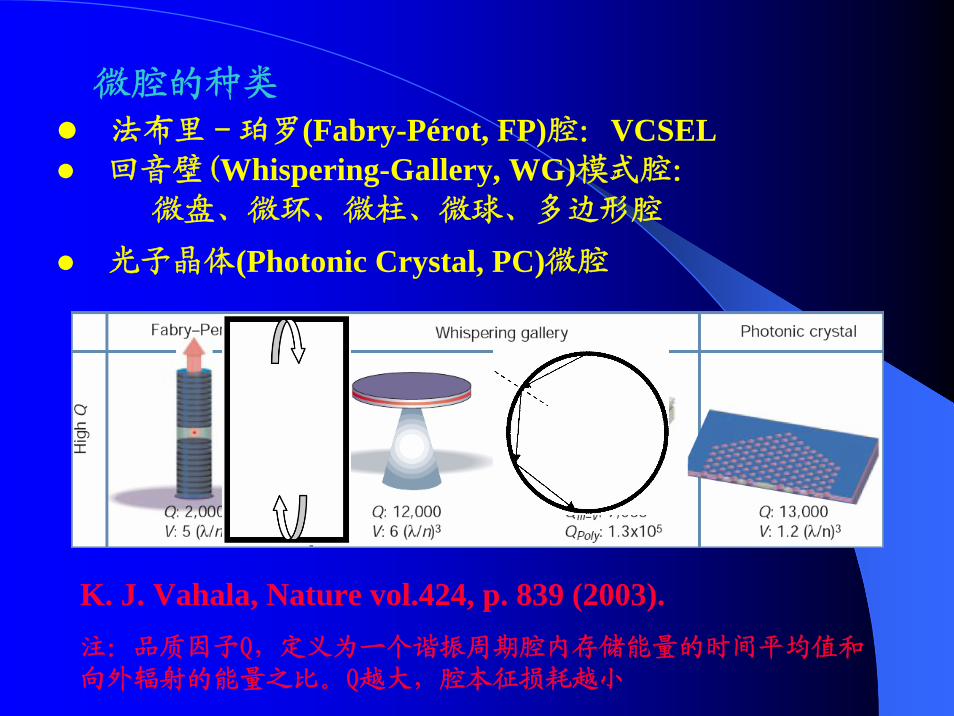
微腔的种类法布里-珀罗(Fabry-Pérot, FP)腔:VCSEL回音壁(Whispering-Gallery, WG)模式腔:
微盘、微环、微柱、微球、多边形腔
光子晶体(Photonic Crystal, PC)微腔
K. J. Vahala, Nature vol.424, p. 839 (2003).注:品质因子Q,定义为一个谐振周期腔内存储能量的时间平均值和向外辐射的能量之比。Q越大,腔本征损耗越小
huang4

幻灯片 5
huang4 yzhuang, 2008-3-6
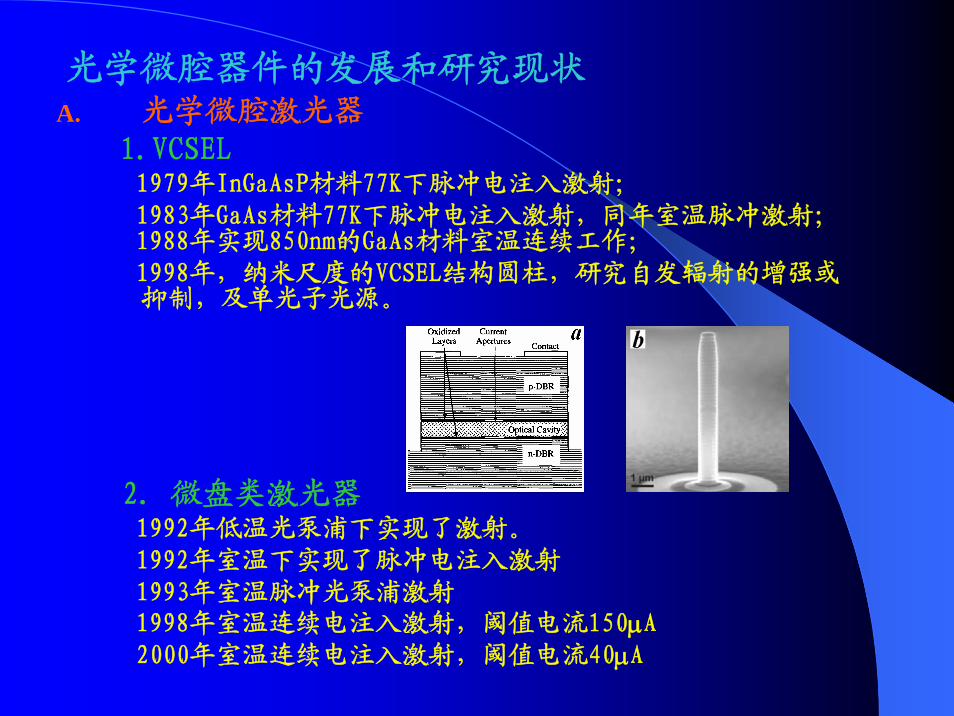
光学微腔器件的发展和研究现状A. 光学微腔激光器
1.VCSEL1979年InGaAsP材料77K下脉冲电注入激射;1983年GaAs材料77K下脉冲电注入激射,同年室温脉冲激射;1988年实现850nm的GaAs材料室温连续工作;1998年,纳米尺度的VCSEL结构圆柱,研究自发辐射的增强或抑制,及单光子光源。
2. 微盘类激光器1992年低温光泵浦下实现了激射。1992年室温下实现了脉冲电注入激射1993年室温脉冲光泵浦激射1998年室温连续电注入激射,阈值电流150μA2000年室温连续电注入激射,阈值电流40μA
研究背景和意义
1. 通信
现代光信息技术的飞速发展对高速率、低功耗、小型
化的光子集成器件的研发提出了要求。
各种功能器件得到广泛关注:激光源(微型、单模、
低阈值),光学滤波器(微型、窄线宽、大自由谱域、可调谐)、光开关(微型、高速)、光调制器(微型、高速)等。
2. 传感
环境保护、安全系统等需要微型、可调谐和高灵敏度
的传感器
3. 物理研究,单光子源,量子信息处理
研究腔量子电动力学和控制自发辐射需要超高品质因子的微型腔。
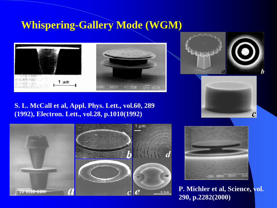
Whispering-Gallery Mode (WGM)
P. Michler et al, Science, vol. 290, p.2282(2000)
S. L. McCall et al, Appl. Phys. Lett., vol.60, 289 (1992), Electron. Lett., vol.28, p.1010(1992)
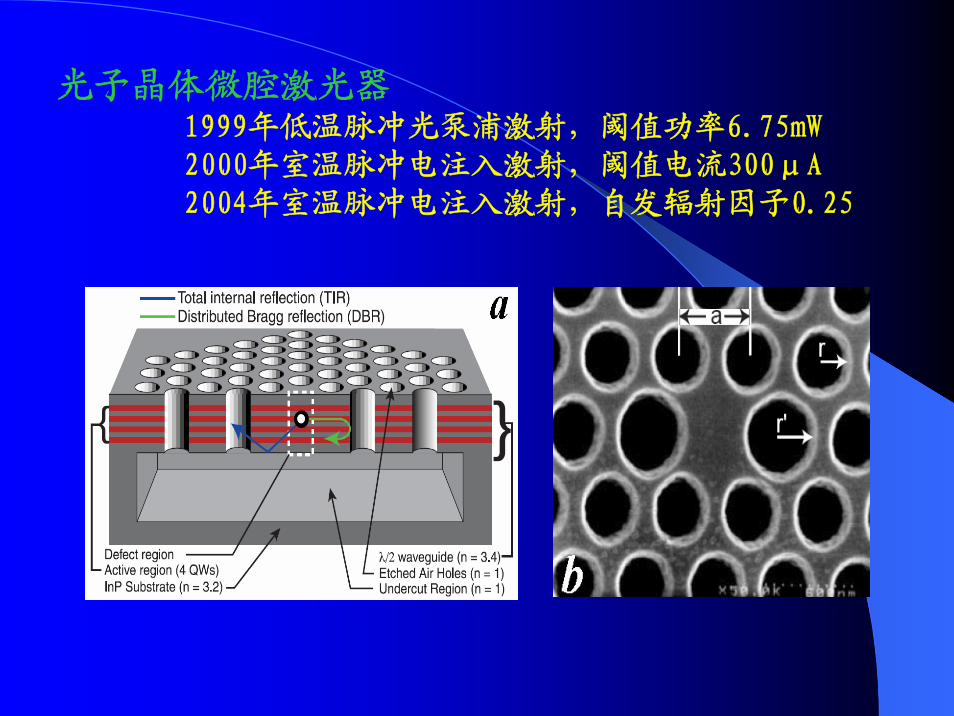
光子晶体微腔激光器1999年低温脉冲光泵浦激射,阈值功率6.75mW2000年室温脉冲电注入激射,阈值电流300μA2004年室温脉冲电注入激射,自发辐射因子0.25
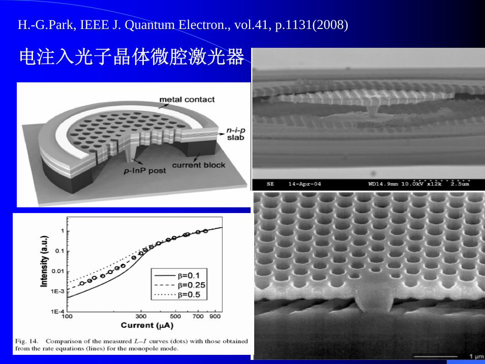
H.-G.Park, IEEE J. Quantum Electron., vol.41, p.1131(2008)
电注入光子晶体微腔激光器
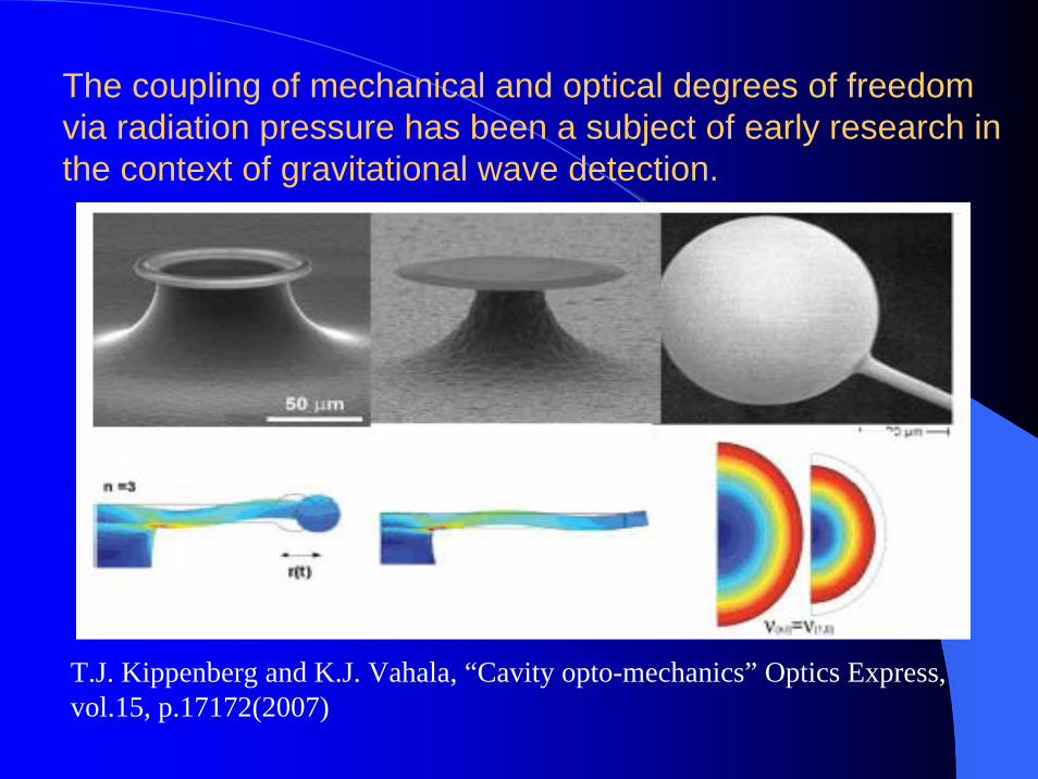
The coupling of mechanical and optical degrees of freedom via radiation pressure has been a subject of early research in the context of gravitational wave detection.
T.J. Kippenberg and K.J. Vahala, “Cavity opto-mechanics” Optics Express, vol.15, p.17172(2007)
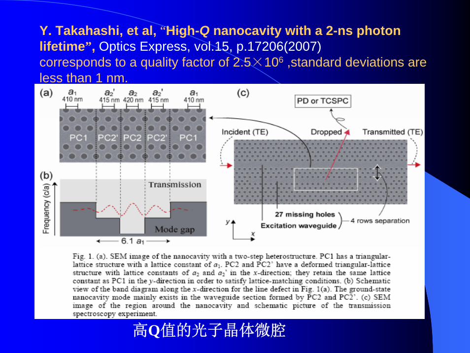
Y. Takahashi, et al, “High-Q nanocavity with a 2-ns photon lifetime”, Optics Express, vol.15, p.17206(2007)corresponds to a quality factor of 2.5×10⁶ ,standard deviations are less than 1 nm.
高Q值的光子晶体微腔
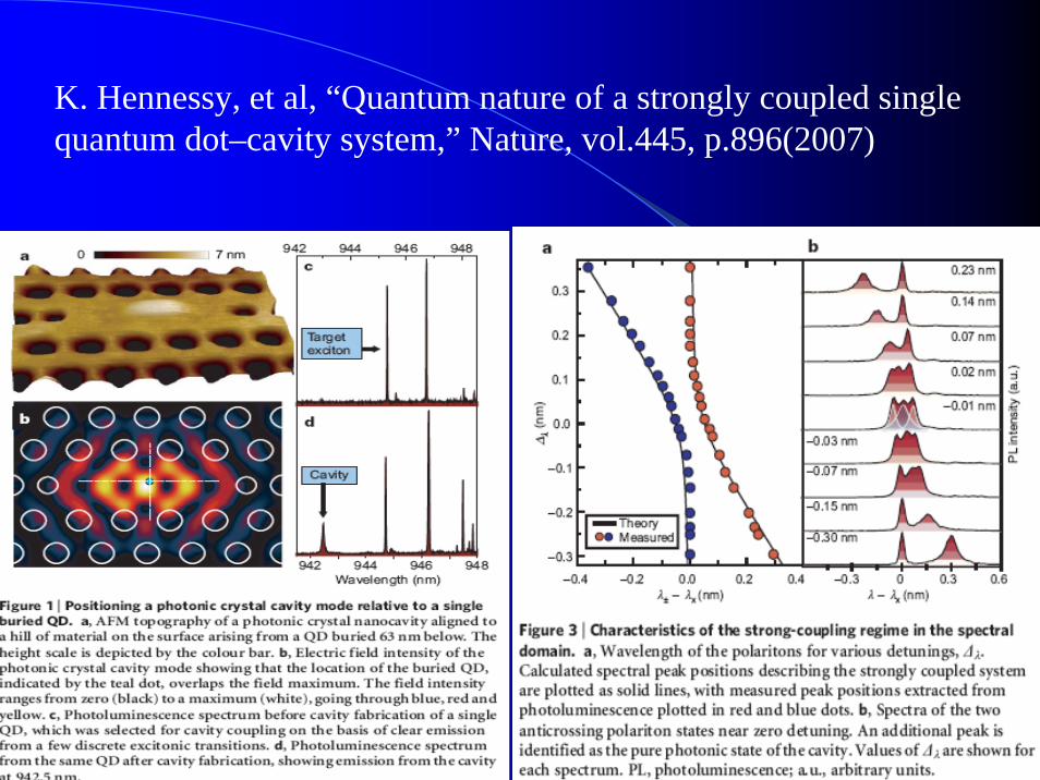
K. Hennessy, et al, “Quantum nature of a strongly coupled single quantum dot–cavity system,” Nature, vol.445, p.896(2007)
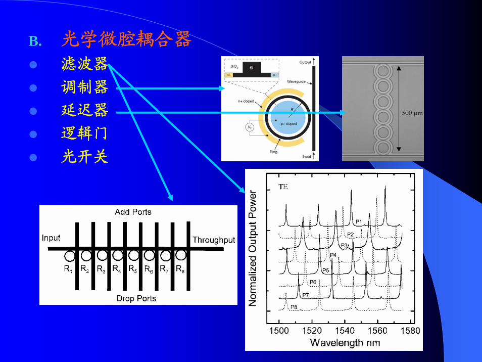
B. 光学微腔耦合器
滤波器
调制器
延迟器
逻辑门
光开关
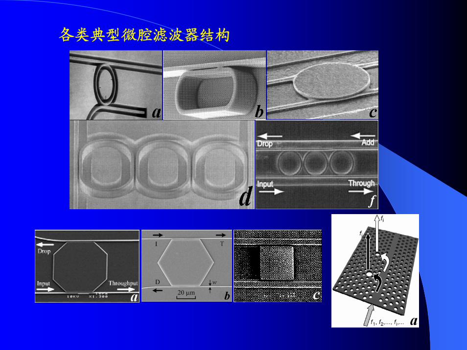
各类典型微腔滤波器结构
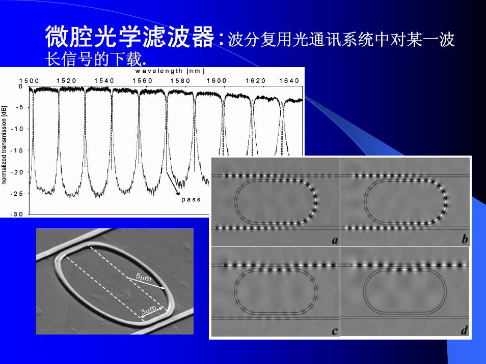
微腔光学滤波器:波分复用光通讯系统中对某一波长信号的下载.
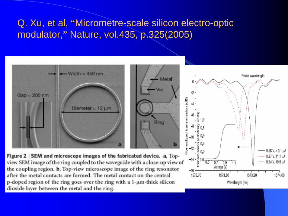
Q. Q. XuXu, et al, , et al, ““Micrometre-scale silicon electro-optic modulator,” Nature, vol.435, p.325(2005)ature, vol.435, p.325(2005)
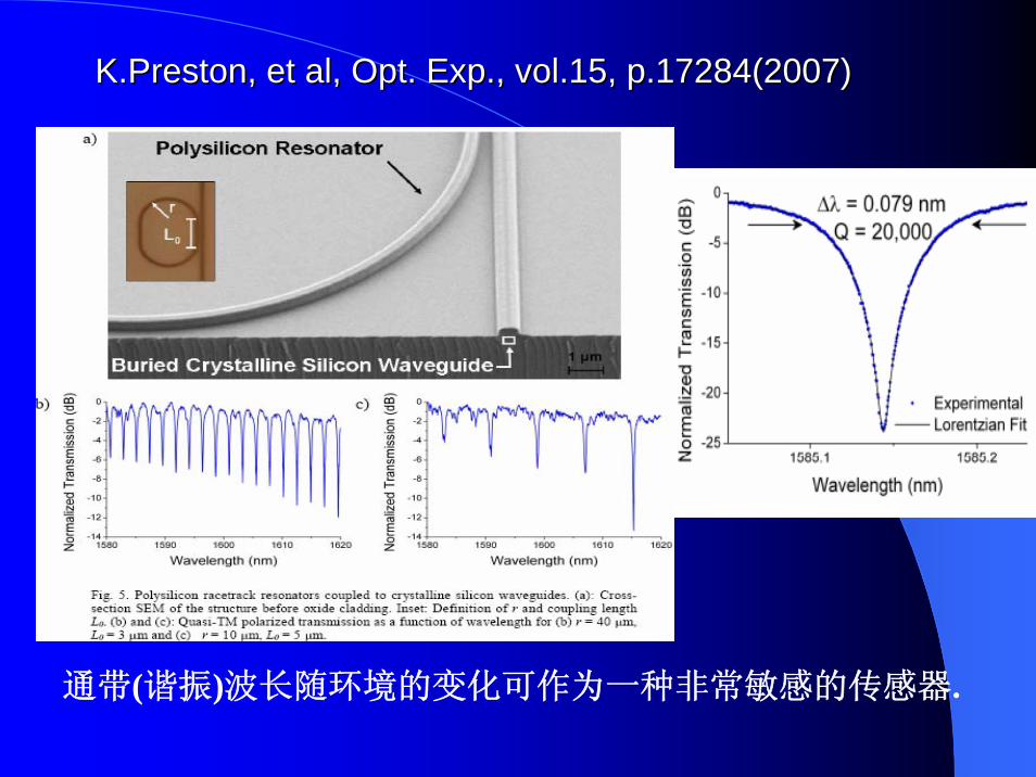
K.PrestonK.Preston, et al, Opt. Exp., vol.15, p.17284(2007), et al, Opt. Exp., vol.15, p.17284(2007)
通带(谐振)波长随环境的变化可作为一种非常敏感的传感器.
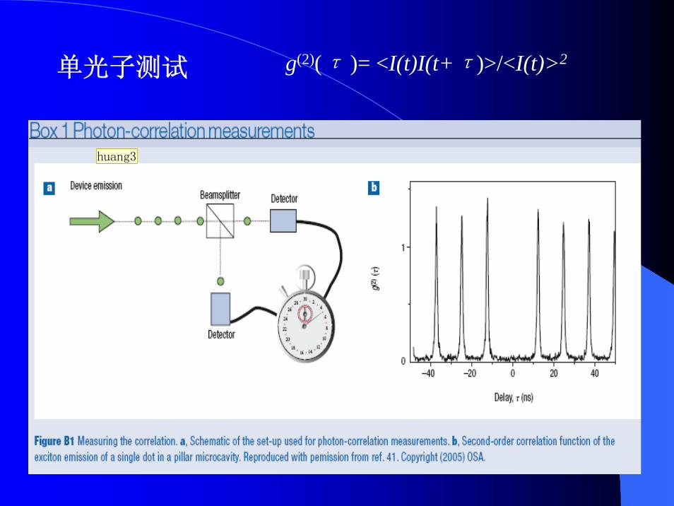
g(2)(τ )= <I(t)I(t+τ)>/<I(t)>2单光子测试
huang3

幻灯片 19
huang3 yzhuang, 2008-3-6
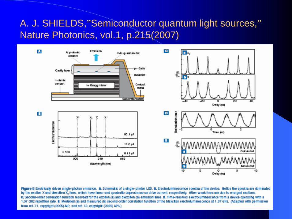
A. J. SHIELDS,”Semiconductor quantum light sources,”Nature Photonics, vol.1, p.215(2007)
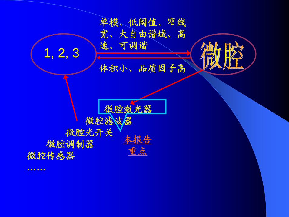
1, 2, 3
单模、低阈值、窄线宽、大自由谱域、高速、可调谐
体积小、品质因子高
微腔激光器微腔滤波器
微腔光开关微腔调制器
微腔传感器……
本报告重点
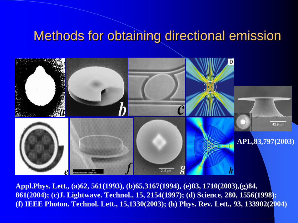
Methods for obtaining directional emissionMethods for obtaining directional emission
Appl.Phys. Lett., (a)62, 561(1993), (b)65,3167(1994), (e)83, 1710(2003),(g)84, 861(2004); (c)J. Lightwave. Technol., 15, 2154(1997); (d) Science, 280, 1556(1998); (f) IEEE Photon. Technol. Lett., 15,1330(2003); (h) Phys. Rev. Lett., 93, 133902(2004)
APL,83,797(2003)
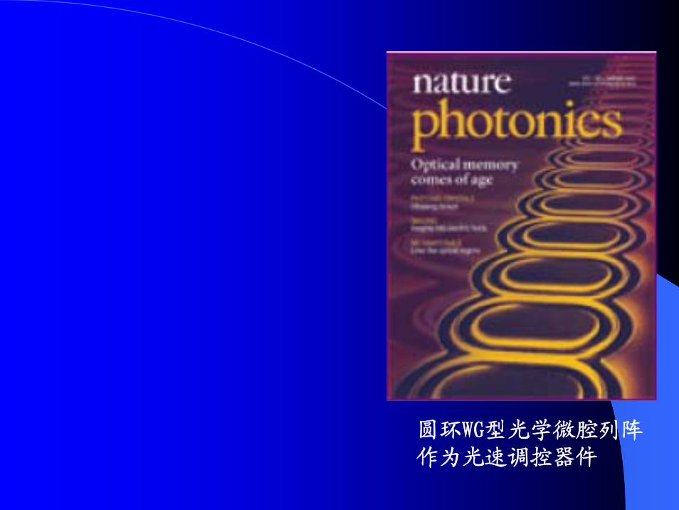
圆环WG型光学微腔列阵作为光速调控器件
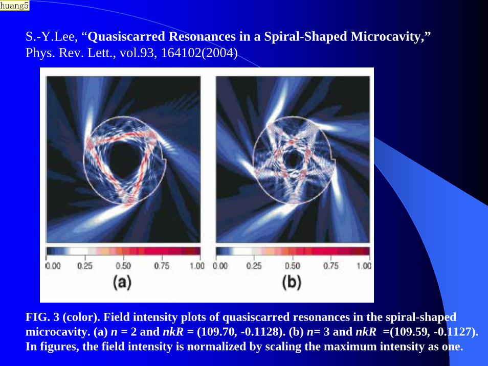
FIG. 3 (color). Field intensity plots of quasiscarred resonances in the spiral-shaped microcavity. (a) n = 2 and nkR = (109.70, -0.1128). (b) n= 3 and nkR =(109.59, -0.1127). In figures, the field intensity is normalized by scaling the maximum intensity as one.
S.-Y.Lee, “Quasiscarred Resonances in a Spiral-Shaped Microcavity,”Phys. Rev. Lett., vol.93, 164102(2004)
huang5

幻灯片 24
huang5 yzhuang, 2008-3-6
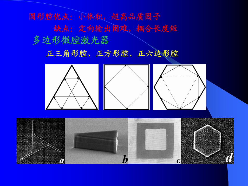
多边形微腔激光器
正三角形腔、正方形腔、正六边形腔
圆形腔优点:小体积,超高品质因子
缺点:定向输出困难,耦合长度短
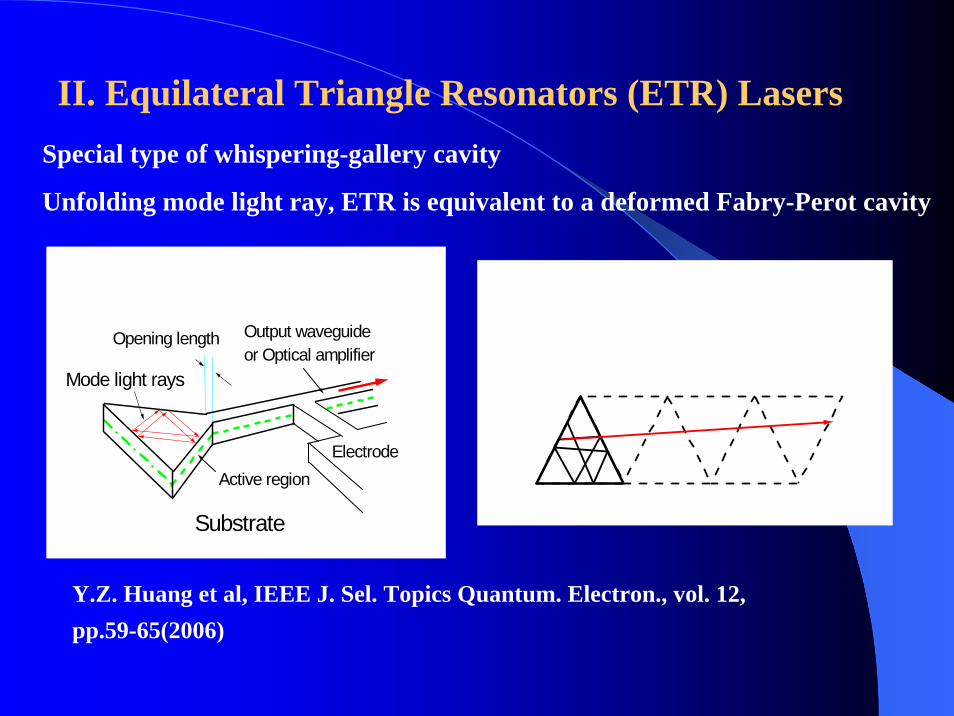
II. Equilateral Triangle Resonators (ETR) Lasers
Mode light rays
Substrate
ElectrodeActive region
Opening length Output waveguideor Optical amplifier
Y.Z. Huang et al, IEEE J. Sel. Topics Quantum. Electron., vol. 12, pp.59-65(2006)
Special type of whispering-gallery cavity
Unfolding mode light ray, ETR is equivalent to a deformed Fabry-Perot cavity
πϕβ lal 23
23
=+
πγξ
ξβϕ
2)1(1)
23(tan2
1
1m
l −++= −
22,)1(3)/32(
3
++−=
ml
Nalm
πϕλ
2)1(
43 πκ +
=ma
m
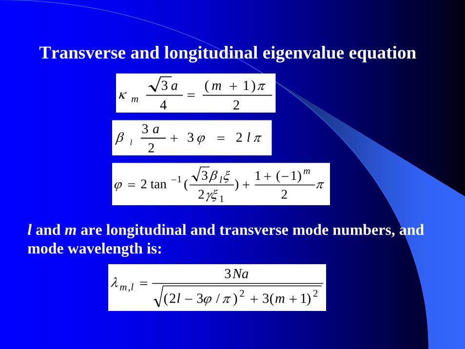
Transverse and longitudinal eigenvalue equation
l and m are longitudinal and transverse mode numbers, and mode wavelength is:
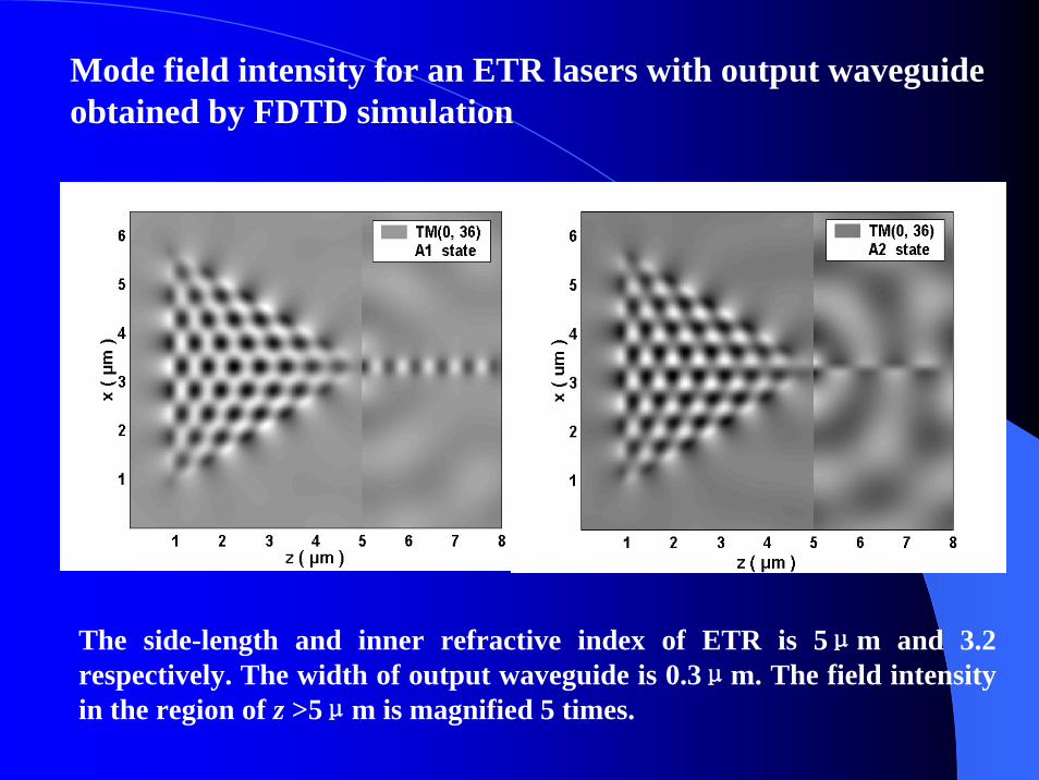
Mode field intensity for an ETR lasers with output waveguide obtained by FDTD simulation
The side-length and inner refractive index of ETR is 5μm and 3.2 respectively. The width of output waveguide is 0.3μm. The field intensity in the region of z >5μm is magnified 5 times.
1500 1510 1520 1530 1540
-90
-85
-80
-75
-70
-65
Inte
nsity
(dB)
Wavelength (nm)
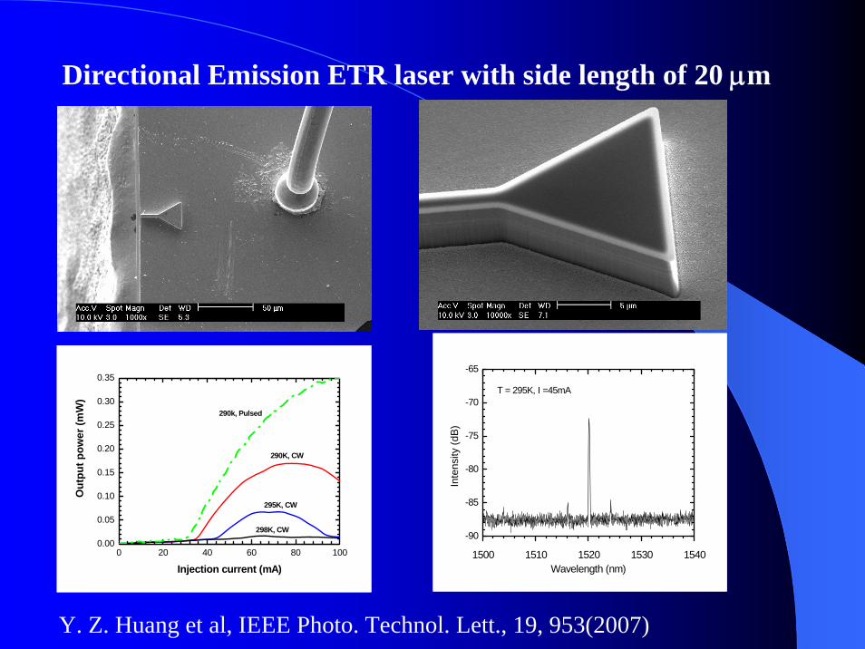
T = 295K, I =45mA
Directional Emission ETR laser with side length of 20 μm
0 20 40 60 80 1000.00
0.05
0.10
0.15
0.20
0.25
0.30
0.35
290k, Pulsed
298K, CW
295K, CW
290K, CW
Out
put p
ower
(mW
)
Injection current (mA)
Y. Z. Huang et al, IEEE Photo. Technol. Lett., 19, 953(2007)
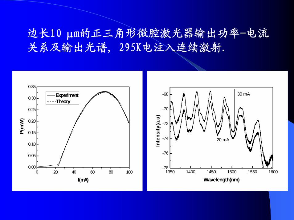
边长10 μm的正三角形微腔激光器输出功率-电流关系及输出光谱, 295K电注入连续激射.
0 20 40 60 80 1000.00
0.05
0.10
0.15
0.20
0.25
0.30
0.35
P(m
W)
I(mA)
Experiment- - - -Theory
1350 1400 1450 1500 1550 1600-78
-76
-74
-72
-70
-68
Inte
nsity
(a.u
)
Wavelength(nm)
20 mA
30 mA
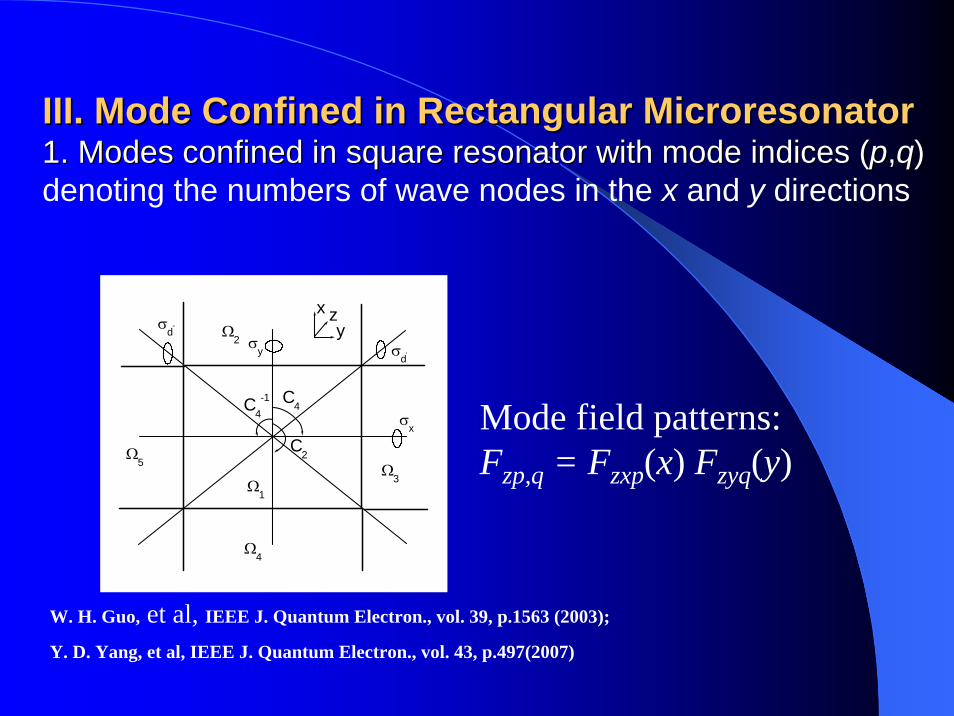
III. Mode Confined in Rectangular III. Mode Confined in Rectangular MicroresonatorMicroresonator1. Modes confined in square resonator with mode indices (1. Modes confined in square resonator with mode indices (pp,,qq) ) denoting the numbers of wave nodes in the x and y directions
Ω5
Ω4
Ω3
Ω2
Ω1
z
C4-1 C4
C2
xy
σy
σd''
σd'
σx
W. H. Guo, et al, IEEE J. Quantum Electron., vol. 39, p.1563 (2003);
Y. D. Yang, et al, IEEE J. Quantum Electron., vol. 43, p.497(2007)
Mode field patterns: Fzp,q = Fzxp(x) Fzyq(y)
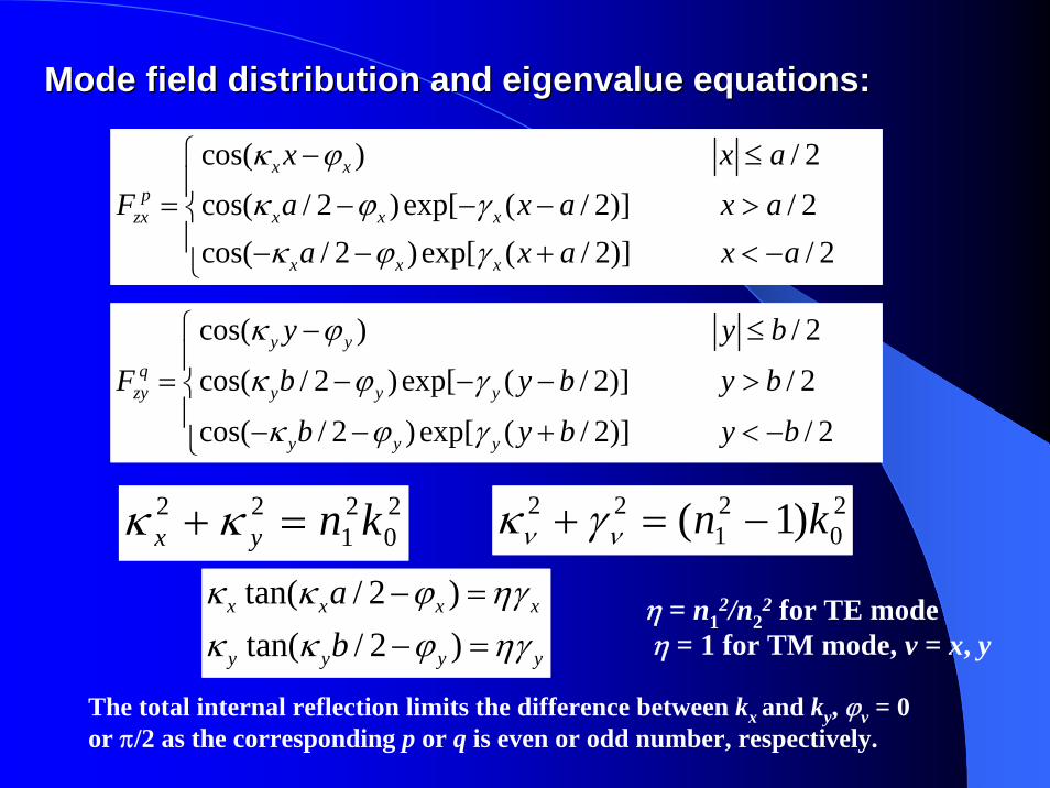
Mode field distribution and Mode field distribution and eigenvalueeigenvalue equations:equations:
The total internal reflection limits the difference between kx and ky, ϕv = 0 or π/2 as the corresponding p or q is even or odd number, respectively.
20
21
22 )1( kn −=+ νν γκ20
21
22 knyx =+ κκ
η = n12/n2
2 for TE mode η = 1 for TM mode, v = x, y
cos( ) / 2cos( / 2 )exp[ ( / 2)] / 2cos( / 2 )exp[ ( / 2)] / 2
x xp
zx x x x
x x x
x x aF a x a x a
a x a x a
κ ϕκ ϕ γ
κ ϕ γ
⎧ − ≤⎪
= − − − >⎨⎪ − − + < −⎩
cos( ) / 2
cos( / 2 )exp[ ( / 2)] / 2
cos( / 2 )exp[ ( / 2)] / 2
y yq
zy y y y
y y y
y y b
F b y b y b
b y b y b
κ ϕ
κ ϕ γ
κ ϕ γ
⎧ − ≤⎪
= − − − >⎨⎪ − − + < −⎩
tan( / 2 )tan( / 2 )
x x x x
y y y y
ab
κ κ ϕ ηγκ κ ϕ ηγ
− =
− =
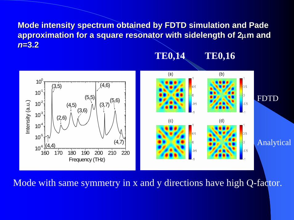
Mode intensity spectrum obtained by FDTD simulation and Mode intensity spectrum obtained by FDTD simulation and PadePadeapproximationapproximation for a square resonator with for a square resonator with sidelengthsidelength of 2of 2μμm and m and nn=3.2=3.2
160 170 180 190 200 210 22010-6
10-5
10-4
10-3
10-2
10-1
100
(4,7)
(5,6)(3,7)
(4,6)
(5,5)
(3,6)(4,5)
(2,6)
(3,5)
(4,4)
Inte
nsity
(a.u
.)
Frequency (THz)
FDTD
Analytical
TE0,14 TE0,16
Mode with same symmetry in x and y directions have high Q-factor.
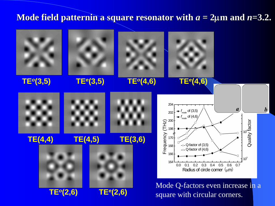
TEo(3,5) TEe(3,5) TEo(4,6) TEe(4,6)
TEo(2,6) TEe(2,6)
TE(4,4) TE(4,5) TE(3,6)
0.0 0.1 0.2 0.3 0.4 0.5 0.6 0.7164
166
168
170
198
200
202
204
103
104
105
fmode of (3,5) fmode of (4,6)
Freq
uenc
y (T
Hz)
Radius of circle corner (μm)
Q-factor of (3,5) Q-factor of (4,6)
Qua
lity
fact
or
Mode Q-factors even increase in a square with circular corners.
Mode field Mode field patterninpatternin a square resonator with a square resonator with a a = 2= 2μμm and m and nn=3.2.=3.2.
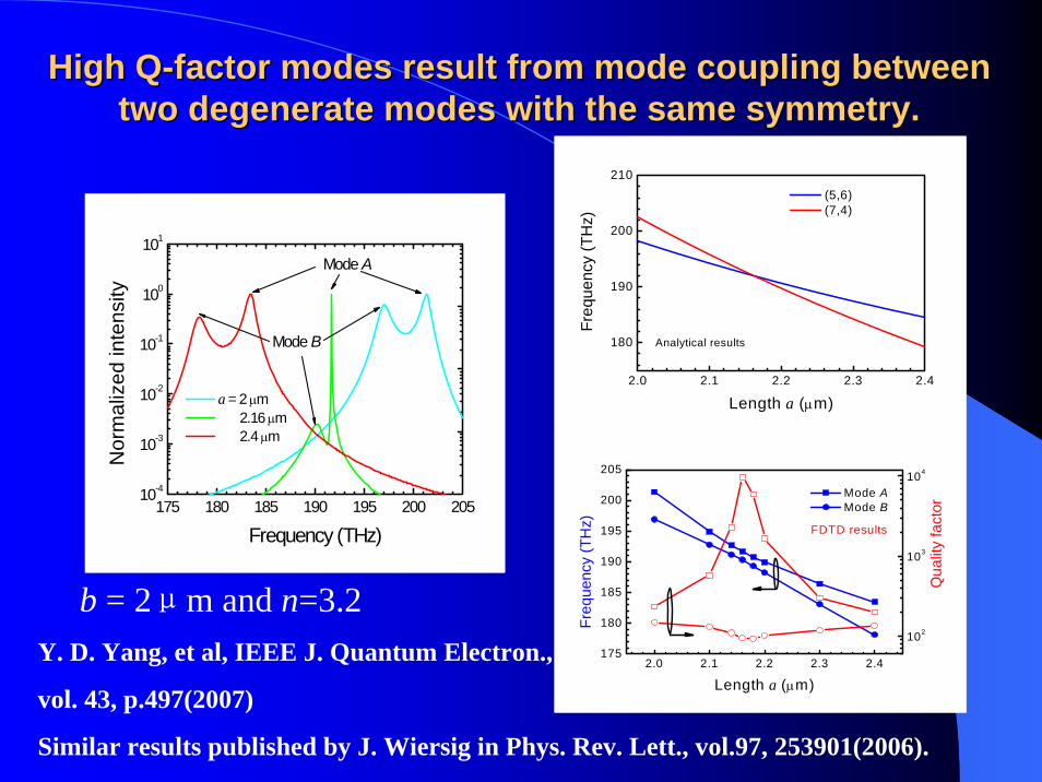
High QHigh Q--factor modes result from mode coupling between factor modes result from mode coupling between two degenerate modes with the same symmetry.two degenerate modes with the same symmetry.
2.0 2.1 2.2 2.3 2.4
180
190
200
210
Freq
uenc
y (T
Hz)
Length a (μm)
(5,6) (7,4)
Analytical results
b = 2μm and n=3.2
175 180 185 190 195 200 20510-4
10-3
10-2
10-1
100
101
Mode B
Nor
mal
ized
inte
nsity
Frequency (THz)
a = 2 μm 2.16 μm 2.4 μm
Mode A
2.0 2.1 2.2 2.3 2.4175
180
185
190
195
200
205
102
103
104
Qua
lity
fact
or
Freq
uenc
y (T
Hz)
Length a (μm)
Mode A Mode B
FDTD results
Y. D. Yang, et al, IEEE J. Quantum Electron.,
vol. 43, p.497(2007)
Similar results published by J. Wiersig in Phys. Rev. Lett., vol.97, 253901(2006).
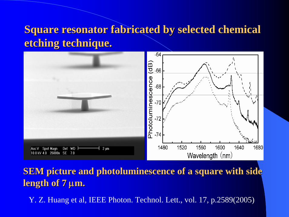
Square resonator fabricated by selected chemical Square resonator fabricated by selected chemical etching technique.etching technique.
SEM picture and photoluminescence of a square with side SEM picture and photoluminescence of a square with side length of 7 length of 7 μμm.m.
Y. Z. Huang et al, IEEE Photon. Technol. Lett., vol. 17, p.2589(2005)
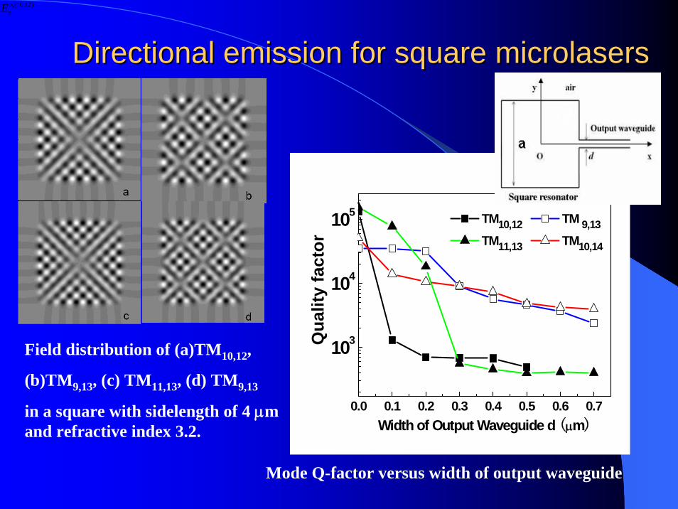
Directional emission for square Directional emission for square microlasersmicrolasers
Field distribution of (a)TM10,12,
(b)TM9,13, (c) TM11,13, (d) TM9,13
in a square with sidelength of 4 μm and refractive index 3.2.
,(10,12)ozE
0.0 0.1 0.2 0.3 0.4 0.5 0.6 0.7
103
104
105
TM10,12 TM 9,13 TM11,13 TM10,14
Qua
lity
fact
or
Width of Output Waveguide d (μm)
Mode Q-factor versus width of output waveguide
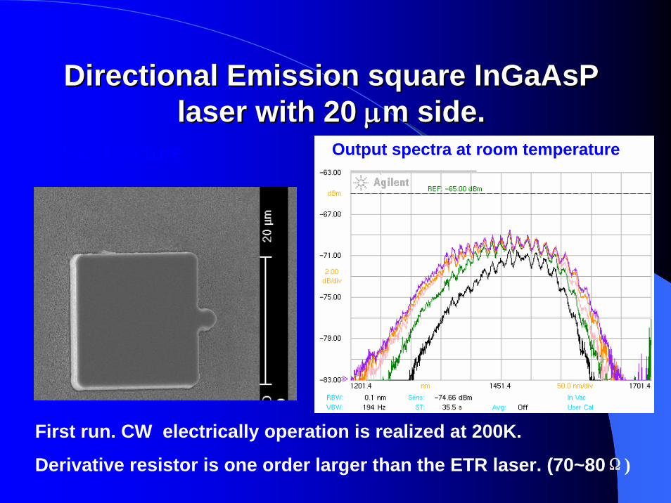
Directional Emission square Directional Emission square InGaAsPInGaAsPlaser with 20 laser with 20 μμmm side.side.
SEM picture Output spectra at room temperature
First run. CW electrically operation is realized at 200K.
Derivative resistor is one order larger than the ETR laser. (70~80Ω)
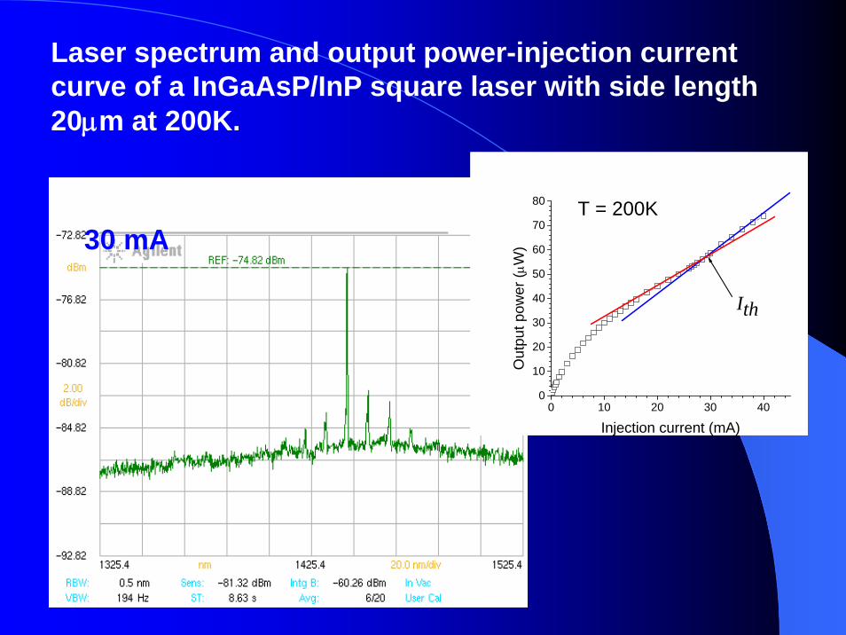
Laser spectrum and output power-injection current curve of a InGaAsP/InP square laser with side length 20μm at 200K.
0 10 20 30 400
10
20
30
40
50
60
70
80 T = 200K
Ith
Out
put p
ower
(μW
)
Injection current (mA)
30 mA
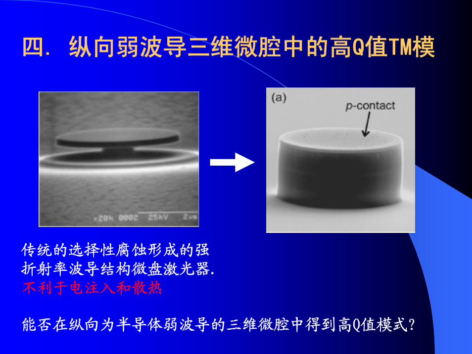
四. 纵向弱波导三维微腔中的高Q值TM模
能否在纵向为半导体弱波导的三维微腔中得到高Q值模式?
传统的选择性腐蚀形成的强折射率波导结构微盘激光器.不利于电注入和散热
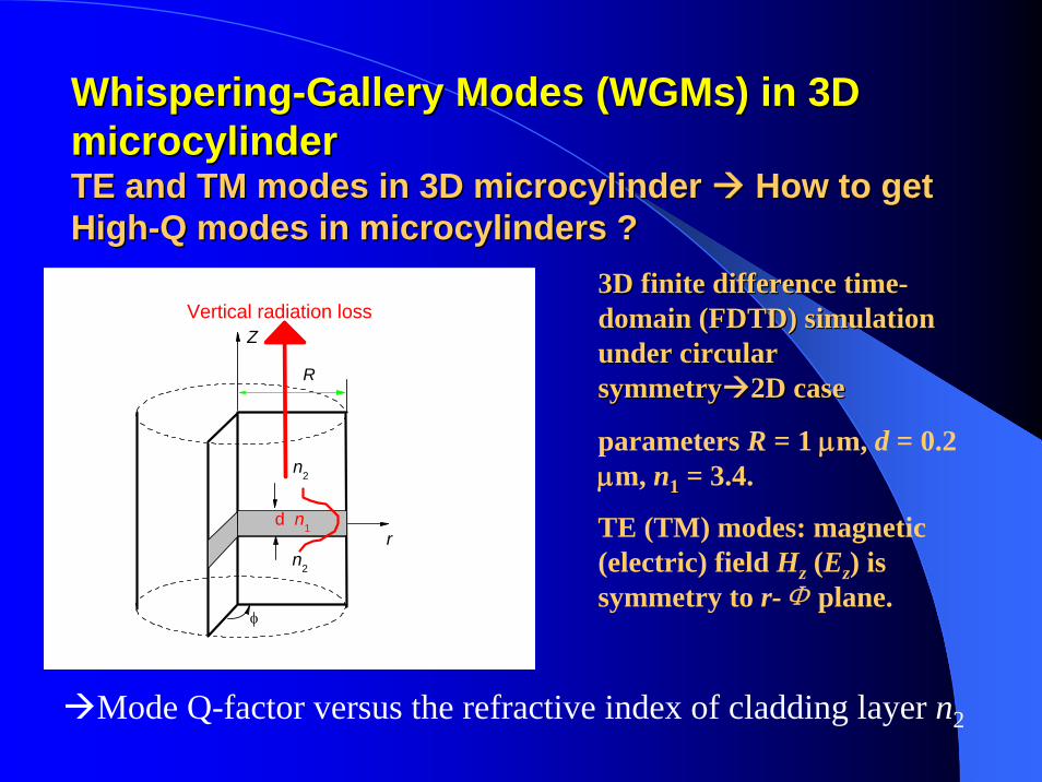
WhisperingWhispering--Gallery Modes (Gallery Modes (WGMsWGMs) in 3D ) in 3D microcylindermicrocylinderTE and TM modes in 3D TE and TM modes in 3D microcylindermicrocylinder How to get How to get HighHigh--Q modes in Q modes in microcylindersmicrocylinders ??
n2
n2
Z
r
φ
d n1
R
Vertical radiation loss
Mode Q-factor versus the refractive index of cladding layer n2
3D finite difference time3D finite difference time--domain (FDTD) simulation domain (FDTD) simulation under circular under circular symmetrysymmetry 2D case2D case
parameters R = 1 μm, d = 0.2 μm, n1 = 3.4.
TE (TM) modes: magnetic (electric) field Hz (Ez) is symmetry to r-Φ plane.
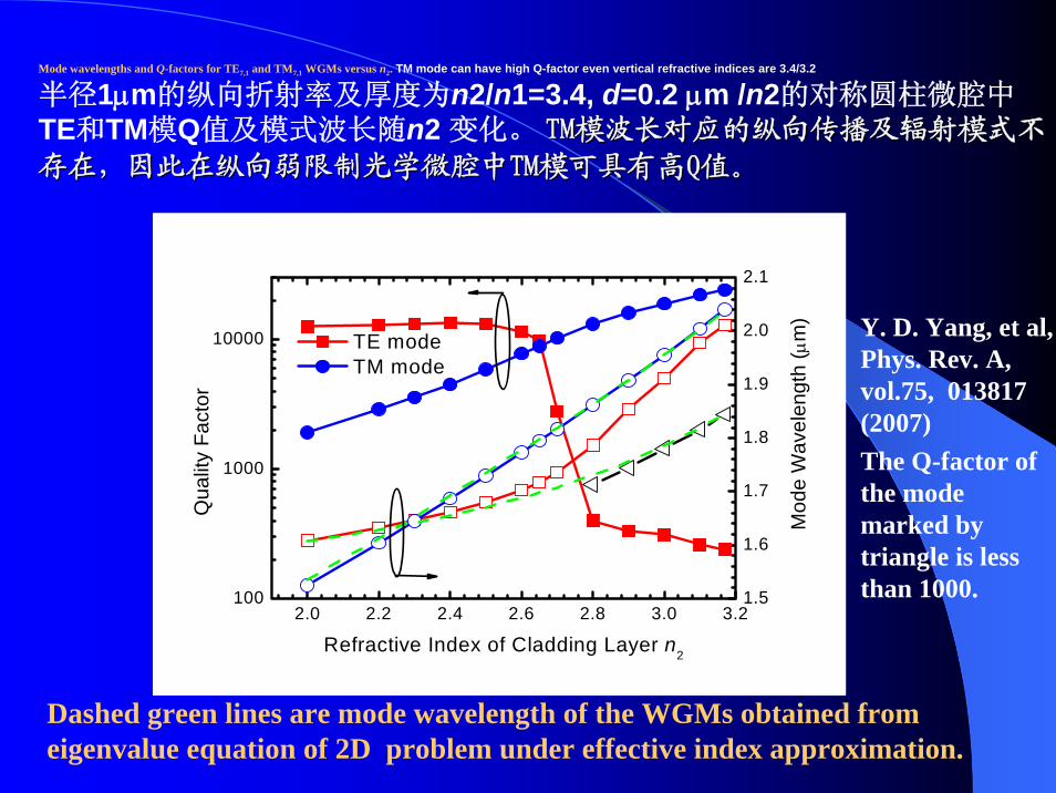
Mode wavelengths and Q-factors for TE7,1 and TM7,1 WGMs versus n2. TM mode can have high Q-factor even vertical refractive indices are 3.4/3.2
半径1μm的纵向折射率及厚度为n2/n1=3.4, d=0.2 μm /n2的对称圆柱微腔中TE和TM模Q值及模式波长随n2 变化。 TMTM模波长对应的纵向传播及辐射模式不模波长对应的纵向传播及辐射模式不
存在,因此在纵向弱限制光学微腔中存在,因此在纵向弱限制光学微腔中TMTM模可具有高模可具有高QQ值。值。
2.0 2.2 2.4 2.6 2.8 3.0 3.2100
1000
10000
1.5
1.6
1.7
1.8
1.9
2.0
2.1
Mod
e W
avel
engt
h (μ
m)
Qua
lity
Fact
or
Refractive Index of Cladding Layer n2
TE mode TM mode
Y. D. Yang, et al, Phys. Rev. A, vol.75, 013817 (2007)The Q-factor of the mode marked by triangle is less than 1000.
Dashed green lines are mode wavelength of the WGMs obtained from eigenvalue equation of 2D problem under effective index approximation.
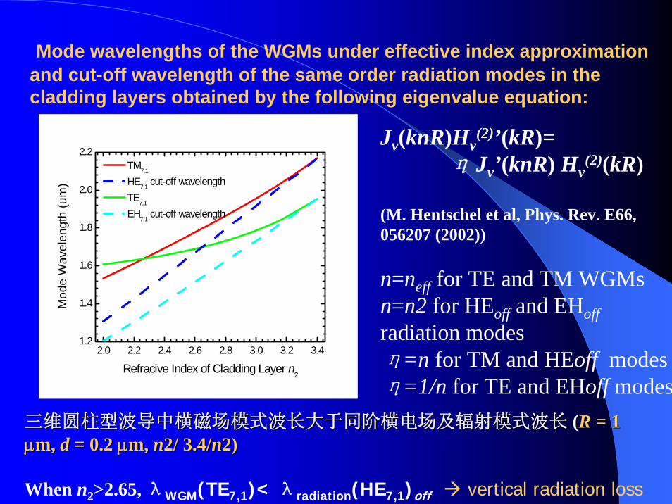
Mode wavelengths of the WGMs under effective index approximation and cut-off wavelength of the same order radiation modes in the cladding layers obtained by the following eigenvalue equation:
三维圆柱型波导中横磁场模式波长大于同阶横电场及辐射模式波长三维圆柱型波导中横磁场模式波长大于同阶横电场及辐射模式波长 ((RR = 1 = 1 μμm, m, dd = 0.2 = 0.2 μμm, m, nn2/2/ 3.4/3.4/nn2)2)
When n2>2.65, λWGM(TE7,1)< λradiation(HE7,1)off vertical radiation loss
2.0 2.2 2.4 2.6 2.8 3.0 3.2 3.41.2
1.4
1.6
1.8
2.0
2.2
Mod
e W
avel
engt
h (u
m)
Refracive Index of Cladding Layer n2
TM7,1
HE7,1 cut-off wavelength TE7,1
EH7,1 cut-off wavelength
Jv(knR)Hv(2)’(kR)=
η Jv’(knR) Hv(2)(kR)
(M. Hentschel et al, Phys. Rev. E66, 056207 (2002))
n=neff for TE and TM WGMsn=n2 for HEoff and EHoffradiation modesη=n for TM and HEoff modes η=1/n for TE and EHoff modes
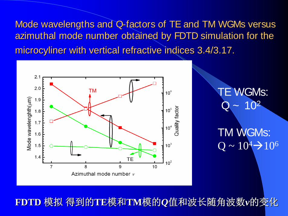
Mode wavelengths and QMode wavelengths and Q--factors of TE and TM factors of TE and TM WGMsWGMs versus versus azimuthalazimuthal mode number obtained by FDTDmode number obtained by FDTD simulation for the simulation for the microcylinermicrocyliner with vertical refractive indices 3.4/3.17.with vertical refractive indices 3.4/3.17.
TE WGMs:Q ~ 102
TM WGMs:Q ~ 104 106
FDTD FDTD 模拟模拟 得到的得到的TETE模和模和TMTM模的模的QQ值和波长随角波数值和波长随角波数vv的变化的变化
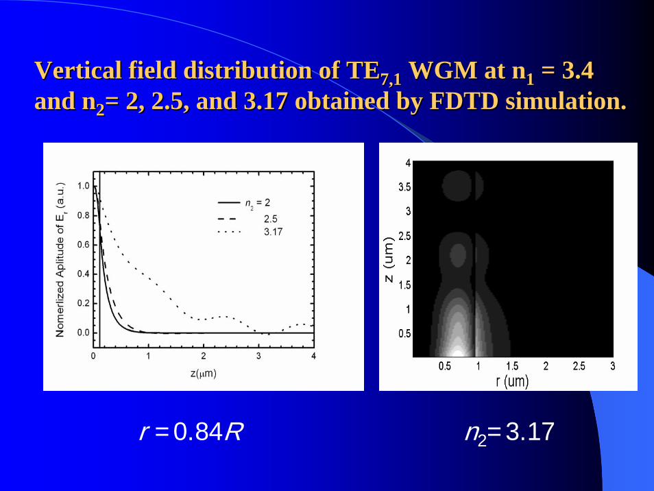
Vertical field distribution of TEVertical field distribution of TE7,17,1 WGM at nWGM at n11 = 3.4 = 3.4 and nand n22= 2, 2.5, and 3.17 obtained by FDTD simulation.= 2, 2.5, and 3.17 obtained by FDTD simulation.
r =0.84R n2=3.17
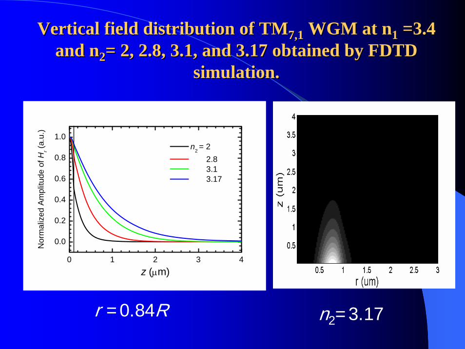
Vertical field distribution of TMVertical field distribution of TM7,17,1 WGM at nWGM at n11 =3.4 =3.4 and nand n22= 2, 2.8, 3.1, and 3.17 obtained by FDTD = 2, 2.8, 3.1, and 3.17 obtained by FDTD
simulation.simulation.
r =0.84R n2=3.17
0 1 2 3 4
0.0
0.2
0.4
0.6
0.8
1.0
Nor
mal
ized
Am
plitu
de o
f Hr (a
.u.)
z (μm)
n2 = 2 2.8 3.1 3.17
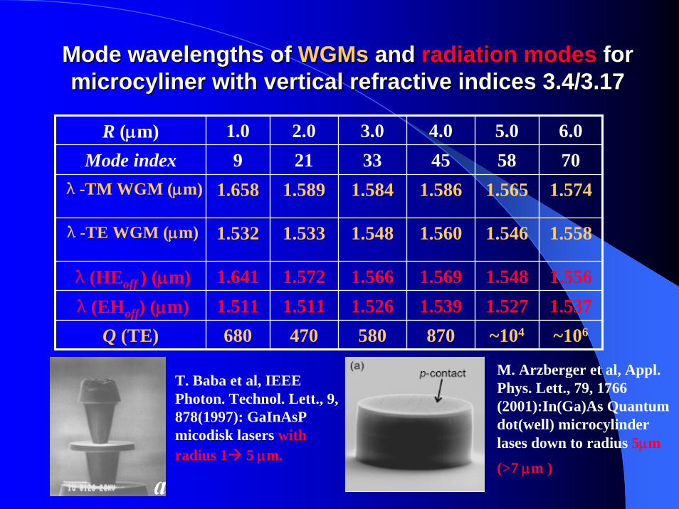
Mode wavelengths ofMode wavelengths of WGMsWGMs andand radiation modes radiation modes for for microcylinermicrocyliner with vertical refractive indices 3.4/3.17with vertical refractive indices 3.4/3.17
R (μm) 1.0 2.0 3.0 4.0 5.0 6.0Mode index 9 21 33 45 58 70
λ-TM WGM (μm) 1.658 1.589 1.584 1.586 1.565 1.574
λ-TE WGM (μm) 1.532 1.533 1.548 1.560 1.546 1.558
λ(HEoff ) (μm) 1.641 1.572 1.566 1.569 1.548 1.556λ(EHoff) (μm) 1.511 1.511 1.526 1.539 1.527 1.537
Q (TE) 680 470 580 870 ~104 ~106
T. Baba et al, IEEE Photon. Technol. Lett., 9, 878(1997): GaInAsPmicodisk lasers with radius 1 5 μm.
M. Arzberger et al, Appl. Phys. Lett., 79, 1766 (2001):In(Ga)As Quantum dot(well) microcylinderlases down to radius 5μm
(>7 μm )
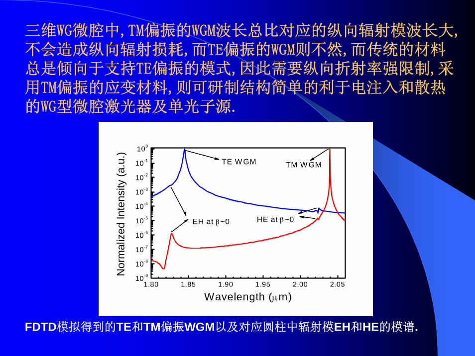
三维WG微腔中,TM偏振的WGM波长总比对应的纵向辐射模波长大,不会造成纵向辐射损耗,而TE偏振的WGM则不然,而传统的材料总是倾向于支持TE偏振的模式,因此需要纵向折射率强限制,采用TM偏振的应变材料,则可研制结构简单的利于电注入和散热的WG型微腔激光器及单光子源.
1.80 1.85 1.90 1.95 2.00 2.0510-9
10-8
10-7
10-6
10-5
10-4
10-3
10-2
10-1
100
HE at β~0EH at β~0
Nor
mal
ized
Inte
nsity
(a.u
.)
Wavelength (μm)
TE W GM TM W GM
FDTD模拟得到的TE和TM偏振WGM以及对应圆柱中辐射模EH和HE的模谱.
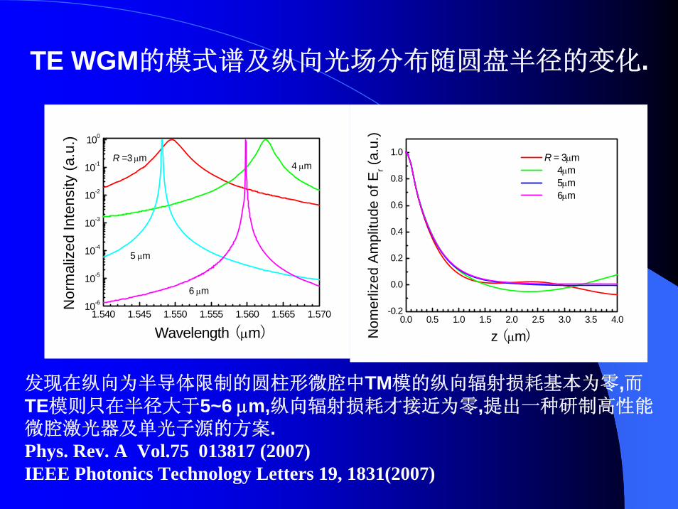
发现在纵向为半导体限制的圆柱形微腔中TM模的纵向辐射损耗基本为零,而TE模则只在半径大于5~6 μm,纵向辐射损耗才接近为零,提出一种研制高性能微腔激光器及单光子源的方案.Phys. Rev. A Vol.75 013817 (2007)IEEE Photonics Technology Letters 19, 1831(2007)
0.0 0.5 1.0 1.5 2.0 2.5 3.0 3.5 4.0-0.2
0.0
0.2
0.4
0.6
0.8
1.0
Nom
erliz
ed A
mpl
itude
of E
r (a.
u.)
z (μm)
R = 3μm 4μm 5μm 6μm
TE WGM的模式谱及纵向光场分布随圆盘半径的变化.
1.540 1.545 1.550 1.555 1.560 1.565 1.57010-6
10-5
10-4
10-3
10-2
10-1
100
Nor
mal
ized
Inte
nsity
(a.u
.)
Wavelength (μm)
R =3 μm4 μm
5 μm
6 μm
五五..结论结论
采用平面工艺研制的室温连续激射定向输出等边三角形激光器可作为集成光学回路的光源(已实现边长10-30微米的激光器激射)。
利用TM模可研制出半径低达1微米的微腔激光器,而且纵向只要普通的半导体波导结构,不须强折射率波导,有希望研制出结构简单的电注入单光子源。

Thank You !