Embed Size (px)
Citation preview
– 1 –
1
• Ce document détaille les specifications des couches basses du CPL G3.
• Il a été soumis auprès du CENELEC (http://www.cenelec.eu) dans le cadre de la normalisation du CPL G3 au titre de “technical specification” (TS). Ce document est issu de la fusion des documents “Spécification de la couche physique CPL G3” et “Spécification de la couche MAC CPL G3”. Des modifications y ont aussi été apportées parmi lesquelles on trouve :
Des changements de style imposés par le gabarit des documents sujets à la standardisation au CENELEC,
L’ajout de la modulation D8PSK.
• Ce document a servi de base aux travaux du projet européen OPEN meter Project, Topic Energy 2008.7.1.1, Project no.: 226369, www.openmeter.com
• Ce document peut être changé sans préavis.
2
• This document deals with G3-PLC low layers.
• This document has been submitted to CENELEC (http://www.cenelec.eu) for technical specification (TS).This document is the merge of “PLC G3 Physical Layer Specification” and “PLC G3 MAC Layer Specification” with additional changes among which :
A change in style due to CENELEC document template,
An addition of a modulation scheme : D8PSK.
• This document is based on the results of the European OPEN meter Project, Topic Energy 2008.7.1.1, Project no.: 226369, www.openmeter.com
• This document can be subject to change without prior notice.
3
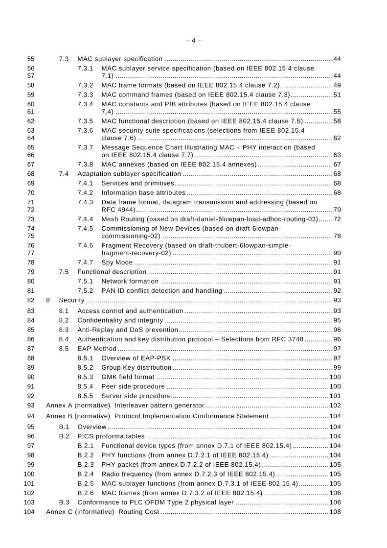
Version Date d’application Titre et nature de la modification Annule et rempla ce
1.0 “Spécification de la couche physique CPL G3”
1.0 “Spécification de la couche MAC CPL G3” 2.0 4/04/2011 “Lower layer profile using OFDM
modulation type 2 ” • Clarifications • Ajout de la modulation D8PSK • Mise en forme selon le gabarit
CENELEC
“Spécification de la couche physique CPL G3” et
“Spécification de la couche MAC CPL G3”
4

– 2 –
Electricity metering - Data exchange over powerline 5
– Part 2: Lower layer profile using OFDM modulation type 2 6
7
– 3 –
CONTENTS 8
1 Scope ............................................................................................................................. 11 9
2 Normative references ..................................................................................................... 11 10
3 Terms and definitions ..................................................................................................... 12 11
4 Acronyms ....................................................................................................................... 12 12
5 Overview ........................................................................................................................ 14 13
6 Physical layer specification ............................................................................................. 15 14
6.1 Overview of the system ......................................................................................... 15 15
6.2 FEC encoder ......................................................................................................... 16 16
6.2.1 Overview ................................................................................................... 16 17
6.2.2 Scrambler .................................................................................................. 17 18
6.2.3 Reed-Solomon encoder ............................................................................. 17 19
6.2.4 Convolutional encoder ............................................................................... 17 20
6.2.5 Robust and Super Robust Modes .............................................................. 18 21
6.2.6 Interleaver ................................................................................................. 18 22
6.3 OFDM modulator ................................................................................................... 20 23
6.3.1 DBPSK / DQPSK / D8PSK mapping ........................................................... 20 24
6.3.2 Frequency domain pre-emphasis ............................................................... 23 25
6.3.3 OFDM Generation (IFFT and CP addition) ................................................. 24 26
6.3.4 Windowing ................................................................................................. 24 27
6.4 OFDM demodulator ............................................................................................... 25 28
6.5 FEC decoder ......................................................................................................... 25 29
6.6 Structure of physical frames .................................................................................. 26 30
6.6.1 General ..................................................................................................... 26 31
6.6.2 Physical data frame ................................................................................... 26 32
6.6.3 Physical ACK / NACK frame ...................................................................... 26 33
6.6.4 Preamble ................................................................................................... 26 34
6.6.5 Frame Control Header (FCH) ..................................................................... 27 35
6.7 System fundamental parameters depending CENELEC bands ............................... 28 36
6.7.1 General specification applied to CENELEC bands ..................................... 28 37
6.7.2 CENELEC A .............................................................................................. 29 38
6.8 Adaptive tone mapping & transmit power control ................................................... 32 39
6.8.1 General ..................................................................................................... 32 40
6.8.2 PN Modulating un-used subcarriers ........................................................... 33 41
6.9 AC phase detection ............................................................................................... 33 42
6.10 Transmitter electrical specifications ....................................................................... 34 43
6.10.1 Output level measurement ......................................................................... 34 44
6.10.2 Transmit spectrum mask (frequency notching) ........................................... 34 45
6.10.3 Spurious transmission ............................................................................... 36 46
6.10.4 Transmit constellation accuracy ................................................................. 36 47
6.10.5 Transmitter Spectral Flatness .................................................................... 37 48
6.11 Physical Layer Primitives ...................................................................................... 38 49
6.11.1 Data primitives .......................................................................................... 38 50
6.11.2 Management primitives .............................................................................. 40 51
7 Data link layer specification ............................................................................................ 44 52
7.1 Introduction ........................................................................................................... 44 53
7.2 Conventions .......................................................................................................... 44 54
– 4 –
7.3 MAC sublayer specification ................................................................................... 44 55
7.3.1 MAC sublayer service specification (based on IEEE 802.15.4 clause 56 7.1) ........................................................................................................... 44 57
7.3.2 MAC frame formats (based on IEEE 802.15.4 clause 7.2) .......................... 49 58
7.3.3 MAC command frames (based on IEEE 802.15.4 clause 7.3) ..................... 51 59
7.3.4 MAC constants and PIB attributes (based on IEEE 802.15.4 clause 60 7.4) ........................................................................................................... 55 61
7.3.5 MAC functional description (based on IEEE 802.15.4 clause 7.5) .............. 58 62
7.3.6 MAC security suite specifications (selections from IEEE 802.15.4 63 clause 7.6) ................................................................................................ 62 64
7.3.7 Message Sequence Chart Illustrating MAC – PHY interaction (based 65 on IEEE 802.15.4 clause 7.7) .................................................................... 63 66
7.3.8 MAC annexes (based on IEEE 802.15.4 annexes) ..................................... 67 67
7.4 Adaptation sublayer specification .......................................................................... 68 68
7.4.1 Services and primitives .............................................................................. 68 69
7.4.2 Information base attributes ........................................................................ 68 70
7.4.3 Data frame format, datagram transmission and addressing (based on 71 RFC 4944) ................................................................................................. 70 72
7.4.4 Mesh Routing (based on draft-daniel-6lowpan-load-adhoc-routing-03) ....... 72 73
7.4.5 Commissioning of New Devices (based on draft-6lowpan-74 commissioning-02) .................................................................................... 78 75
7.4.6 Fragment Recovery (based on draft-thubert-6lowpan-simple-76 fragment-recovery-02) ............................................................................... 90 77
7.4.7 Spy Mode .................................................................................................. 91 78
7.5 Functional description ........................................................................................... 91 79
7.5.1 Network formation ..................................................................................... 91 80
7.5.2 PAN ID conflict detection and handling ...................................................... 92 81
8 Security .......................................................................................................................... 93 82
8.1 Access control and authentication ......................................................................... 93 83
8.2 Confidentiality and integrity ................................................................................... 95 84
8.3 Anti-Replay and DoS prevention ............................................................................ 96 85
8.4 Authentication and key distribution protocol – Selections from RFC 3748 .............. 96 86
8.5 EAP Method .......................................................................................................... 97 87
8.5.1 Overview of EAP-PSK ............................................................................... 97 88
8.5.2 Group Key distribution ............................................................................... 99 89
8.5.3 GMK field format ..................................................................................... 100 90
8.5.4 Peer side procedure ................................................................................ 100 91
8.5.5 Server side procedure ............................................................................. 101 92
Annex A (normative) Interleaver pattern generator ............................................................. 102 93
Annex B (normative) Protocol Implementation Conformance Statement ............................. 104 94
B.1 Overview ............................................................................................................. 104 95
B.2 PICS proforma tables .......................................................................................... 104 96
B.2.1 Functional device types (from annex D.7.1 of IEEE 802.15.4) .................. 104 97
B.2.2 PHY functions (from annex D.7.2.1 of IEEE 802.15.4) ............................. 104 98
B.2.3 PHY packet (from annex D.7.2.2 of IEEE 802.15.4) ................................. 105 99
B.2.4 Radio frequency (from annex D.7.2.3 of IEEE 802.15.4) .......................... 105 100
B.2.5 MAC sublayer functions (from annex D.7.3.1 of IEEE 802.15.4) ............... 105 101
B.2.6 MAC frames (from annex D.7.3.2 of IEEE 802.15.4) ................................ 106 102
B.3 Conformance to PLC OFDM Type 2 physical layer .............................................. 106 103
Annex C (informative) Routing Cost ................................................................................... 108 104
– 5 –
Annex D (normative) Channel access ................................................................................ 109 105
D.1 Overview ............................................................................................................. 109 106
D.2 Interframe (IFS) Spacing ..................................................................................... 109 107
D.3 CSMA-CA ............................................................................................................ 110 108
D.4 Priority ................................................................................................................ 112 109
D.5 ARQ .................................................................................................................... 113 110
D.6 Segmentation and reassembly overview .............................................................. 115 111
Annex E (normative) Modified MAC sublayer data primitives .............................................. 116 112
E.1 MCPS-DATA.request ........................................................................................... 116 113
E.2 MCPS-DATA.indication ....................................................................................... 117 114
Annex F (normative) MAC acknowledgement ..................................................................... 120 115
Annex G (normative) Adaptation sublayer service primitives .............................................. 121 116
G.1 ADP Data service ................................................................................................ 121 117
G.1.1 Overview ................................................................................................. 121 118
G.1.2 ADPD-DATA.request ............................................................................... 121 119
G.1.3 ADPD-DATA.confirm ............................................................................... 124 120
G.1.4 ADPD-DATA.indication ............................................................................ 124 121
G.2 ADP Management service ................................................................................... 125 122
G.2.1 Overview ................................................................................................. 125 123
G.2.2 ADPM-DISCOVERY.request .................................................................... 126 124
G.2.3 ADPM-DISCOVERY.confirm .................................................................... 126 125
G.2.4 ADPM-NETWORK-START.request .......................................................... 127 126
G.2.5 ADPM-NETWORK-START.confirm........................................................... 128 127
G.2.6 ADPM-NETWORK-JOIN.request .............................................................. 128 128
G.2.7 ADPM-NETWORK-JOIN.confirm .............................................................. 129 129
G.2.8 ADPM-NETWORK-JOIN.indication .......................................................... 130 130
G.2.9 ADPM-NETWORK-LEAVE.request .......................................................... 130 131
G.2.10 ADPM-NETWORK-LEAVE.indication ....................................................... 131 132
G.2.11 ADPM-NETWORK-LEAVE.confirm ........................................................... 132 133
G.2.12 ADPM-RESET.request ............................................................................. 132 134
G.2.13 ADPM-RESET.confirm ............................................................................. 133 135
G.2.14 ADPM-GET.request ................................................................................. 133 136
G.2.15 ADPM-GET.confirm ................................................................................. 134 137
G.2.16 ADPM-SET.request ................................................................................. 135 138
G.2.17 ADPM-SET.confirm.................................................................................. 135 139
G.2.18 ADPM-NETWORK-STATUS.indication ..................................................... 136 140
G.2.19 ADPM-ROUTE-DISCOVERY.request ....................................................... 137 141
G.2.20 ADPM-ROUTE-DISCOVERY.confirm ....................................................... 137 142
G.2.21 ADPM-PATH-DISCOVERY.request .......................................................... 138 143
G.2.22 ADPM-PATH-DISCOVERY.confirm .......................................................... 138 144
G.2.23 ADPM-LBP.request ................................................................................. 139 145
G.2.24 ADPM-LBP.confirm .................................................................................. 140 146
G.2.25 ADPM-LBP.indication .............................................................................. 141 147
G.2.26 ADPM-BUFFER.indication ....................................................................... 142 148
G.3 Behavior to MAC Indications ............................................................................... 142 149
G.3.1 Overview ................................................................................................. 142 150
G.3.2 MCPS-DATA.indication ............................................................................ 142 151
G.3.3 MLME-ASSOCIATE.indication ................................................................. 142 152
– 6 –
G.3.4 MLME-DISASSOCIATE.indication ........................................................... 142 153
G.3.5 MLME-BEACON-NOTIFY.indication ......................................................... 142 154
G.3.6 MLME-GTS.indication .............................................................................. 143 155
G.3.7 MLME-ORPHAN.indication ...................................................................... 143 156
G.3.8 MLME-COMM-STATUS.indication ........................................................... 143 157
G.3.9 MLME-SYNC-LOSS.indication ................................................................. 143 158
Annex H (normative) Device Starting Sequence of messages ............................................ 144 159
160
List of Figures 161
Figure 1 – PLC OFDM Type 2 communication profile ............................................................ 15 162
Figure 2 – Block diagram of transceiver ................................................................................ 16 163
Figure 3 – Data scrambler..................................................................................................... 17 164
Figure 4 – Convolutional encoder ......................................................................................... 18 165
Figure 5 – Interleaver............................................................................................................ 19 166
Figure 6 – Spreading behaviour of the Interleaver ................................................................. 20 167
Figure 7 – DBPSK and Robust constellation diagram ............................................................ 21 168
Figure 8 – DQPSK constellation diagram .............................................................................. 22 169
Figure 9 – D8PSK constellation diagram ............................................................................... 23 170
Figure 10 – Block diagram of the pre-emphasis filter ............................................................. 24 171
Figure 11 – IFFT Input / Output and CP addition ................................................................... 24 172
Figure 12 – Raised Cosine windowing................................................................................... 24 173
Figure 13 – Overlap / add ..................................................................................................... 25 174
Figure 14 – Typical physical data frame structure ................................................................. 26 175
Figure 15 – Example of typical physical ACK / NACK frame structure (content of FCH 176 is submitted to variation of the physical channel) .................................................................. 26 177
Figure 16 – Zero-crossing detector ....................................................................................... 33 178
Figure 17 – Transmit spectrum mask .................................................................................... 34 179
Figure 18 – Spectrum with two notches inserted to cohabitate with S-FSK PLC modem ........ 36 180
Figure 19 – Data transmission flow (MAC → PHY) ................................................................ 38 181
Figure 20 – Management Primitive flow ................................................................................ 41 182
Figure 21 – Frame structure of a Tone Map Response message ........................................... 53 183
Figure 22 – PAN start message sequence chart .................................................................... 64 184
Figure 23 – Active scan message sequence chart ................................................................. 65 185
Figure 24 – Data transmission message sequence chart ....................................................... 66 186
Figure 25 – Channel estimation (tone map request) message sequence chart ...................... 67 187
Figure 28 – Path Request (PREQ) message format .............................................................. 77 188
Figure 29 – Path Reply (PREP) message format ................................................................... 78 189
Figure 30 – LBP message format .......................................................................................... 81 190
Figure 31 – Embedded EAP message format (generic) ......................................................... 82 191
Figure 32 – Configuration parameter format .......................................................................... 83 192
Figure 33 – Bootstrapping protocol messages sequence chart .............................................. 84 193
Figure 34 – Bootstrapping protocol messages forwarding ..................................................... 85 194
Figure 35 – Message sequence chart during removal of a device by the coordinator ............. 89 195
Figure 36 – Message sequence chart during removal of a device by itself............................. 90 196
– 7 –
Figure 37 – CONFLICT message format ............................................................................... 92 197
Figure 38 – LBP and EAP Relaying Capabilities ................................................................... 94 198
Figure 39 – Confidentiality and Security ................................................................................ 95 199
Figure 40 – EAP-PSK Key Hierarchy overview ...................................................................... 99 200
Figure 41 – GMK field format .............................................................................................. 100 201
Figure D.1 – IFS ................................................................................................................. 110 202
Figure D.2 – CSMA/CA algorithm ........................................................................................ 112 203
Figure D.3 – Priority Contention Windows ............................................................................ 112 204
Figure D.4 – Transmit ARQ ................................................................................................. 114 205
Figure D.5 – Receive ARQ .................................................................................................. 114 206
207
List of Tables 208
Table 1 – DBPSK and Robust encoding table of k-th Subcarrier ........................................... 20 209
Table 2 – DQPSK encoding table of k-th subcarrier .............................................................. 21 210
Table 3 – DQPSK encoding table of k-th subcarrier .............................................................. 22 211
Table 4 – The Raised Cosine samples .................................................................................. 25 212
Table 5 – FCH bit fields ........................................................................................................ 27 213
Table 6 – Physical parameter values applied to CENELEC bands ......................................... 29 214
Table 7 – CENELEC bands ................................................................................................... 29 215
Table 8 – CENELEC A – Number of carriers ......................................................................... 29 216
Table 9 – CENELEC A – Phase vector definition ................................................................... 29 217
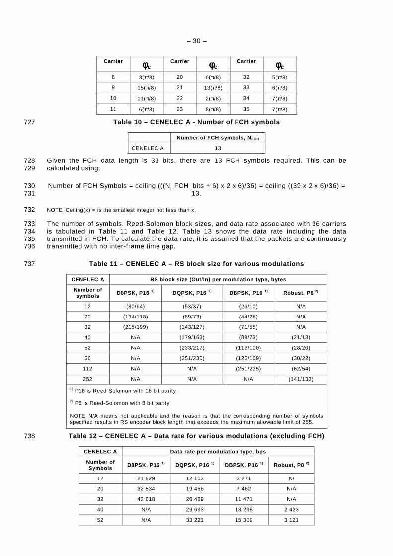
Table 10 – CENELEC A - Number of FCH symbols ............................................................... 30 218
Table 11 – CENELEC A – RS block size for various modulations .......................................... 30 219
Table 12 – CENELEC A – Data rate for various modulations (excluding FCH)....................... 30 220
Table 13 – CENELEC A – Data rate for various modulations (including FCH) ....................... 31 221
Table 14 – Notched subcarriers in S-FSK cohabitation mode ................................................ 35 222
Table 15 – PD-DATA.request primitive .................................................................................. 39 223
Table 16 – PD-DATA.confirm primitive .................................................................................. 39 224
Table 17 – PD-DATA.indication primitive .............................................................................. 39 225
Table 18 – PD-ACK.request primitive .................................................................................... 40 226
Table 19 – PD-ACK.confirm primitive .................................................................................... 40 227
Table 20 – PD-ACK.indication primitive................................................................................. 40 228
Table 21 – PLME-SET.request primitive ................................................................................ 41 229
Table 22 – PLME-SET.confirm primitive ................................................................................ 42 230
Table 23 – PLME-GET.confirm primitive ............................................................................... 43 231
Table 24 – PLME_SET.TRX_STATE.request primitive .......................................................... 43 232
Table 25 – PLME_SET.TRX_STATE.confirm primitive .......................................................... 43 233
Table 26 – PLME_CS.confirm primitive ................................................................................. 44 234
Table 27 – Selections from IEEE 802.15.4 clause 7.1 ........................................................... 45 235
Table 28 – QualityOfService parameter definition ................................................................. 49 236
Table 29 – Selections from clause 7.2 of the IEEE 802.15.4 ................................................. 49 237
Table 30 – General MAC frame format .................................................................................. 51 238
Table 31 – Segment control fields ......................................................................................... 51 239
– 8 –
Table 32 – Selections from clause 7.3 of the IEEE 802.15.4 ................................................. 51 240
Table 33 – MAC command frames supported ........................................................................ 52 241
Table 34 – Tone map response format .................................................................................. 53 242
Table 35 – Tone Map Response message description for CENELEC A band ........................ 53 243
Table 36 – Modulation Method Field ..................................................................................... 54 244
Table 37 – Selections from clause 7.4 of the 802.15.4 .......................................................... 55 245
Table 38 – Additional MAC sublayer constants to IEEE 802.15.4 clause 7.4.1 ...................... 56 246
Table 39 – Additional attributes to IEEE 802.15.4 clause 7.4.2 ............................................. 57 247
Table 40 – MAC sublayer attributes and their associated ID ................................................. 58 248
Table 41 – Selections from clause 7.5 of the IEEE 802.15.4 ................................................. 58 249
Table 42 – Neighbour Table .................................................................................................. 61 250
Table 43 – Selections from clause 7.6 of the IEEE 802.15.4 ................................................. 62 251
Table 44 – Selections from clause 7.7 of the IEEE 802.15.4 ................................................. 63 252
Table 45 – Selections from MAC annexes of the IEEE 802.15.4 ............................................ 68 253
Table 46 – Adaptation sublayer IB attributes ......................................................................... 68 254
Table 47 – Broadcast log table entry ..................................................................................... 69 255
Table 48 – Selections from RFC 4944 ................................................................................... 70 256
Table 49 – Command frame header identifier ........................................................................ 71 257
Table 50 – CFA value field description .................................................................................. 72 258
Table 51 – Selections from draft-daniel-6lowpan-load-adhoc-routing-03 ............................... 72 259
Table 52 – Broadcast log table ............................................................................................. 74 260
Table 53 – Path Request (PREQ) fields’ definition ................................................................ 78 261
Table 54 – Path Reply (PREP) fields’ definition .................................................................... 78 262
Table 55 – Selections from draft-6lowpan-commissioning-02 ................................................ 79 263
Table 56 – T & Code fields in LBP message ......................................................................... 82 264
Table 57 – Selections from draft-thubert-6lowpan-simple-fragment-recovery-02 .................... 90 265
Table 58 – Selections from RFC 3748 ................................................................................... 96 266
Table 59 – Selections from RFC 4764 ................................................................................... 97 267
Table B.1 – PICS – Functional device types (from annex D.7.1 of IEEE 802.15.4) .............. 104 268
Table B.2 – PICS – PHY functions (from annex D.7.2.1 of IEEE 802.15.4) .......................... 104 269
Table B.3 – PICS – PHY packet (from annex D.7.2.2 of IEEE 802.15.4).............................. 105 270
Table B.4 – PICS – Radio frequency (from annex D.7.2.3 of IEEE 802.15.4) ...................... 105 271
Table B.5 – PICS – MAC sublayer functions (from annex D.7.3.1 of IEEE 802.15.4) ........... 105 272
Table B.6 – PICS – MAC frames (from annex D.7.3.2 of IEEE 802.15.4) ............................. 106 273
Table B.7 – conformance to PLC OFDM Type 2 physical layer ............................................ 106 274
Table D.1 – Segment control fields ..................................................................................... 115 275
Table E.1 – MCPS-DATA.request parameters ..................................................................... 116 276
Table E.2 – MCPS-DATA.request parameters ..................................................................... 118 277
Table G.1 – Parameters of the ADPD-DATA.request primitive ............................................. 121 278
Table G.2 – Parameters of the ADPD-DATA.confirm primitive ............................................. 124 279
Table G.3 – Parameters of the ADPD-DATA.indication primitive ......................................... 125 280
Table G.4 – Parameters of the ADPM-DISCOVERY.request primitive ................................. 126 281
Table G.5 – Parameters of the ADPM-DISCOVERY.confirm primitive ................................. 126 282
– 9 –
Table G.6 – PAN descriptor structure specification ............................................................. 127 283
Table G.7 – Parameters of the ADPM-NETWORK-START.request primitive ........................ 127 284
Table G.8 – Parameters of the ADPM-NETWORK-START.confirm primitive ........................ 128 285
Table G.9 – Parameters of the ADPM-NETWORK-JOIN.request primitive ........................... 129 286
Table G.10 – Parameters of the ADPM-NETWORK-JOIN.confirm primitive ......................... 129 287
Table G.11 – Parameters of the ADPM-NETWORK-JOIN.indication primitive ...................... 130 288
Table G.12 – Parameters of the ADPM-NETWORK-LEAVE.request primitive ...................... 131 289
Table G.13 – Parameters of the ADPM-NETWORK-LEAVE.indication primitive ................... 131 290
Table G.14 – Parameters of the ADPM-NETWORK-LEAVE.confirm primitive ...................... 132 291
Table G.15 – Parameters of the ADPM-RESET.confirm primitive ........................................ 133 292
Table G.16 – Parameters of the ADPM-GET.request primitive ............................................ 134 293
Table G.17 – Parameters of the ADPM-GET.confirm primitive ............................................. 134 294
Table G.18 – Parameters of the ADPM-SET.request primitive ............................................. 135 295
Table G.19 – Parameters of the ADPM-SET.confirm primitive ............................................. 136 296
Table G.20 – Parameters of the ADPM-NETWORK-STATUS.indication primitive ................ 136 297
Table G.21 – Parameters of the ADPM-ROUTE-DISCOVERY.request primitive .................. 137 298
Table G.22 – Parameters of the ADPM-ROUTE-DISCOVERY.confirm primitive .................. 137 299
Table G.23 – Parameters of the ADPM-PATH-DISCOVERY.request primitive ..................... 138 300
Table G.24 – Parameters of the ADPM-PATH-DISCOVERY.confirm primitive ..................... 139 301
Table G.25 – Parameters of the ADPM-LBP.request primitive ............................................. 139 302
Table G.26 – Parameters of the ADPM-LBP.confirm primitive ............................................. 140 303
Table G.27 – Parameters of the ADPM-LBP.indication primitive .......................................... 141 304
Table G.28 – Parameters of the ADPM-BUFFER.indication primitive................................... 142 305
306
307
308

– 10 –
INTRODUCTION 309
This Technical Specification is based on the results of the European OPEN meter Project, 310 Topic Energy 2008.7.1.1, Project no.: 226369, www.openmeter.com. 311
312
– 11 –
Electricity metering – Data exchange over powerline – Part 2: Lower layer 313 profile using OFDM modulation Type 2 314
1 Scope 315
This standard specifies the Physical and MAC Layer for an Orthogonal Frequency Division 316 Multiplexing (OFDM) Power Line Communications (PLC) system 317
The physical layer provides a modulation technique that efficiently utilizes the allowed 318 bandwidth within the CENELEC band (3 kHz – 148,5 kHz) thereby allowing the use of 319 advanced channel coding techniques. This combination enables a very robust communication 320 in the presence of narrowband interference, impulsive noise, and frequency selective 321 attenuation. 322
The medium access control (MAC) layer allows the transmission of MAC frames through the 323 use of the power line physical channel. It provides data services, frame validation control, 324 node association and secure services. 325
2 Normative references 326
The following referenced documents are indispensable for the application of this document. 327 For dated references, only the edition cited applies. For undated references, the latest edition 328 of the referenced document (including any amendments) applies. 329
EN 50065-1:2001, Signalling on low-voltage electrical installations in the frequency range 3 330 kHz to 148,5 kHz – Part 1: General requirements, frequency bands and electromagnetic 331 disturbances 332
IEC 61334-5-1:2001, Distribution automation using distribution line carrier systems – Part 5-1: 333 Lower layer profiles – The spread frequency shift keying (S-FSK) profile 334
IEEE 802:2001, IEEE Standard for Local and Metropolitan Area Networks – Overview and 335 Architecture 336
IEEE 802.15.4:2006, IEEE Standard for Information technology – Telecommunications and 337 information exchange between systems – Local and metropolitan area networks – Specific 338 requirements – Part 15.4: Wireless Medium Access (MAC) and Physical Layer (PHY) 339 Specifications for Low-Rate Wireless Personal Area Networks (WPANs) 340
IEEE 802.2:1998, IEEE Standard for Information technology – Telecommunications and 341 information exchange between systems – Local and metropolitan area networks – Specific 342 requirements – Part 2: Logical Link Control 343
IETF RFC 2284: PPP Extensible Authentication Protocol (EAP) [online]. Edited by L. Blunk, J. 344 Vollbrecht. March 1998. Available from: http://www.ietf.org/rfc/rfc2284.txt 345
IETF RFC 2865: Remote Authentication Dial In User Service (RADIUS) [online]. Edited by C. 346 Rigney, S. Willems, A. Rubens, W. Simpson. June 2000. Available from: 347 http://www.ietf.org/rfc/rfc2865.txt 348
IETF RFC 3748: Extensible Authentication Protocol (EAP) [online]. Edited by B. Aboda, L. 349 Blunk, J. Vollbrecht, J. Carlson, H. Levkowetz. June 2004. Available from: 350 http://www.ietf.org/rfc/rfc3748.txt 351
IETF RFC 4291: IP Version 6 Addressing Architecture [online]. Edited by R. Hinden, S. 352 Deering. February 2006. Available from: http://www.ietf.org/rfc/rfc4291.txt 353

– 12 –
IETF RFC 4764: The EAP-PSK Protocol: A Pre-Shared Key Extensible Authentication 354 Protocol (EAP) Method [online]. Edited by F. Bersani, H. Tschofenig. January 2007. Available 355 from: http://www.ietf.org/rfc/rfc4764.txt 356
IETF RFC 4862: IPv6 Stateless Address Autoconfiguration [online]. Edited by S. Thomson, T. 357 Narten, T. Jinmey. September 2007. Available from: http://www.ietf.org/rfc/rfc4862.txt 358
IETF RFC 4944: Transmission of IPv6 Packets over IEEE 802.15.4 Networks [online]. Edited 359 by G. Montenegro, N. Kushalnagar, D. Culler. September 2007. Available from: 360 http://www.ietf.org/rfc/rfc4944.txt 361
NOTE The following IETF documents are in the draft stage. 362
IETF draft-daniel-6lowpan-load-adhoc-routing-03: 6LoWPAN Ad Hoc On-Demand Distance 363 Vector Routing (LOAD) [online]. Edited by K. Kim, S. Daniel, G. Montenegro, S. Yoo, N. 364 Kushalnager. June 19, 2007. Available from: http://tools.ietf.org/id/draft-daniel-6lowpan-load-365 adhoc-routing-03.txt 366
IETF draft-6lowpan-commissioning-02: Commissioning in 6LoWPAN [online]. Edited by K. 367 Kim, S. Shams, S. Yoo, S. Park, G. Mulligan. July 15, 2008. Available from: 368 http://tools.ietf.org/html/draft-daniel-6lowpan-commissioning-02 369
IETF draft-thubert-6lowpan-simple-fragment-recovery-02: LoWPAN simple fragment Recovery 370 [online]. Edited by P. Thubert. May 29, 2008. Available from: http://tools.ietf.org/html/draft-371 thubert-6lowpan-simple-fragment-recovery-02 372
3 Terms and definitions 373
For the purposes of this document, the following definitions, together with those of IEEE 374 802.15.4-2006 and RFC 4944, apply. 375
Bit fields can be expressed in various notations : 376
– a field beginning with “0b” is followed by a binary sequence, 377
– a field beginning with “0h” is followed by a hexadecimal sequence. 378
4 Acronyms 379
AAA Authentication, Authorization, and Accounting
ACK ACKnowledge
ADP Adaptation
AFE Analog Front End
AGC Automatic Gain Control
BPSK Binary Phase Shift Keying
CC Convolutional Code
CENELEC European Committee for Electrotechnical Standardization
CFA Contention Free Access
CP Cyclic Prefix
CRC Cyclic Redundancy Check
DBPSK Differential Binary Phase Shift Keying
DQPSK Differential Quadrature Phase Shift Keying
D8PSK Differential Eight Phase Shift Keying
FCH Frame Control Header

– 13 –
FEC Forward Error Correction
FFT Fast Fourier Transform
FL Frame Length
GF Galois Field
GI Guard Interval
GMK Group Master Key
ICI Inter Carrier Interference
IEEE Institute of Electrical and Electronics Engineers
IEC International Electrotechnical Commission
IFFT Inverse Fast Fourier Transform
IS Information System
LBD LoWPAN BootStrapping Device
LBP LoWPAN Boostrapping Protocol
LSB Least Significant Bit
LSF Last Segment Flag
MAC Media Access Control
MIB Management Information Base
MPDU MAC Protocol Data Unit
MSB Most Significant Bit
NACK Negative ACKnowledge
NIB Neighbour Information Base
NSDU Network Service Data Unit
OFDM Orthogonal Frequency Division Multiplexing
PAN Personal Area Network
PAR Peak to Average Ratio
PDC Phase Detection Counter
PHY PHYsical layer
PIB PAN Information Base
PLC Power Line Communication
PN Pseudo-Noise Sequence
POS Personal Operating Space
PPDU PHY Protocol Data Unit
PPM Parts Per Million
PSD Power Spectrum Density
PSDU PHY Service Data Unit
RADIUS Remote Authentification Dial in User Service
RC Repetition Code
RES Reserved (bit fields)
RMS Root Mean Square
RS Reed-Solomon
RX Receiver
S-FSK Spread Frequency Shift Keying
S-Robust Super Robust
SC Segment Count
SN Sequence Number

– 14 –
SNR Signal to Noise Ratio
SYNCP, SYNCM SYNChronization symbols
TMI Tone Map Index
TMR Tone Map Request
TX Transmit
6LoWPAN IPv6 over Low power Wireless Personal Area Networks
Furthermore, the abbreviations given in the following clauses apply also: 380
– Clause 4 of IEEE 802.15.4-2006; 381
– Clause 1.2 of RFC 4944. 382
5 Overview 383
The present standard constitutes the specification for PLC OFDM Type 2 communication 384 based on OFDM modulation, and details the Data Link layer of the protocol stack. 385
This standard has been developed to meet the following aims: 386
– Robustness: the communication profile must be suited to severe environments; 387
– Performance: it must take full advantage of the CENELEC A band; 388
– Simplicity: it must be simple to implement, install (Plug and Play), operate and maintain; 389
– Flexibility: it must be compatible with diverse applications and network topologies; 390
– Security: it must offer a safe environment for the promotion of Value Added services; 391
– Openness: it must be based on open standards in order to support multi-supplier 392 solutions; 393
– Scalability: it must support all future metering developments. 394
To this end, the OFDM PLC protocol stack aggregates several layers and sublayers that form 395 the PLC OFDM Type 2 profile: 396
– A robust high-performance physical layer based on OFDM and adapted to the PLC 397 environment; 398
– A MAC sublayer of the IEEE type, well suited to low data rates; 399
– IPv6, the new generation of IP (Internet Protocol), which widely opens the range of 400 potential applications and services; 401
– And to allow good IPv6 and MAC interoperability, an adaptation sublayer taken from the 402 Internet world and called 6LoWPAN. 403
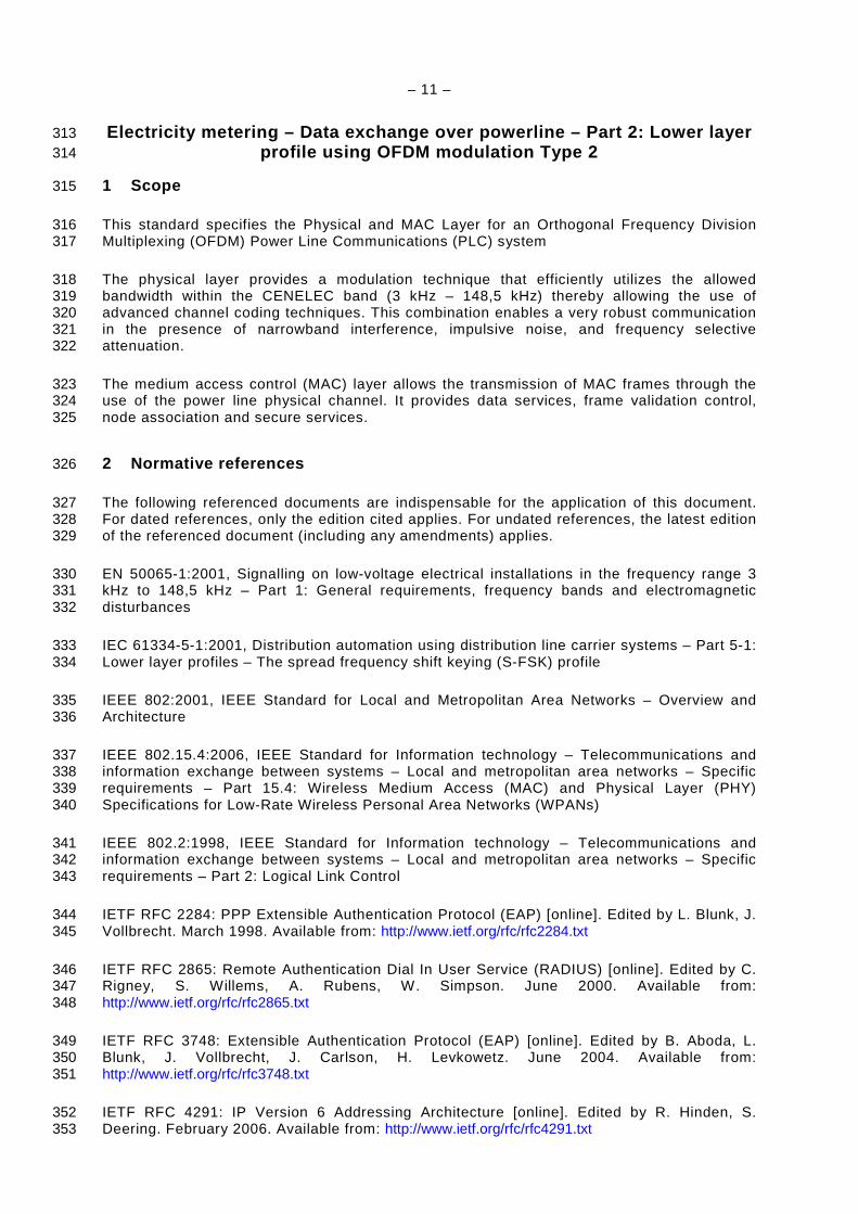
Figure 1 gives an overall view of the PLC OFDM Type 2 communication profile: 404
– 15 –
Internet Application
PLC Media
Physical layerOFDM Modulation
MAC SublayerIEEE 802.15.4 - 2006
UDPIETF RFC 768
IPv6IETF RFC 2460
6LoWPAN Adaptation Sub-layerIETF RFC 4944
405
Figure 1 – PLC OFDM Type 2 communication profile 406
6 Physical layer specification 407
6.1 Overview of the system 408
The power line channel is very hostile. Channel characteristics and parameters vary with 409 frequency, location, time and the type of equipment connected to it. The lower frequency 410 regions from 10 kHz to 200 kHz are especially susceptible to interference. Furthermore, the 411 power line is a very frequency selective channel. Besides background noise, it is subject to 412 impulsive noise often occurring at 50/60Hz and group delays up to several hundred 413 microseconds. 414
OFDM uses advanced modulation and channel coding techniques and thereby it can 415 efficiently utilize the limited bandwidth of CENELEC A band and facilitates a very robust 416 communication over the power line channel. 417
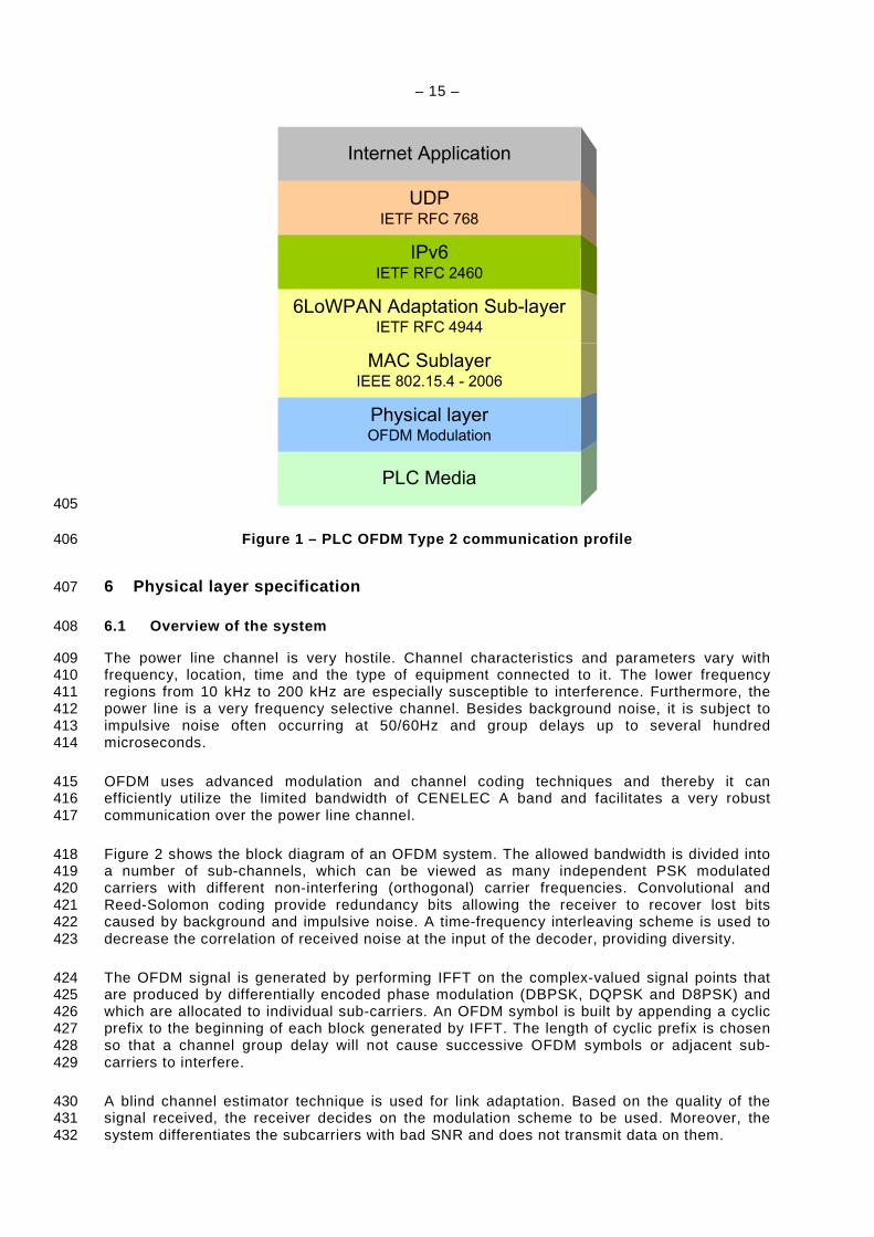
Figure 2 shows the block diagram of an OFDM system. The allowed bandwidth is divided into 418 a number of sub-channels, which can be viewed as many independent PSK modulated 419 carriers with different non-interfering (orthogonal) carrier frequencies. Convolutional and 420 Reed-Solomon coding provide redundancy bits allowing the receiver to recover lost bits 421 caused by background and impulsive noise. A time-frequency interleaving scheme is used to 422 decrease the correlation of received noise at the input of the decoder, providing diversity. 423
The OFDM signal is generated by performing IFFT on the complex-valued signal points that 424 are produced by differentially encoded phase modulation (DBPSK, DQPSK and D8PSK) and 425 which are allocated to individual sub-carriers. An OFDM symbol is built by appending a cyclic 426 prefix to the beginning of each block generated by IFFT. The length of cyclic prefix is chosen 427 so that a channel group delay will not cause successive OFDM symbols or adjacent sub-428 carriers to interfere. 429
A blind channel estimator technique is used for link adaptation. Based on the quality of the 430 signal received, the receiver decides on the modulation scheme to be used. Moreover, the 431 system differentiates the subcarriers with bad SNR and does not transmit data on them. 432

– 16 –
433
Figure 2 – Block diagram of transceiver 434
6.2 FEC encoder 435
6.2.1 Overview 436
The FEC encoder is composed of a Reed-Solomon encoder followed by a convolutional 437 encoder. In Robust mode, an extra encoder, namely, Repetition Code (RC) is used after the 438 convolutional encoder in order to repeat the bits at the output of convolutional. 439
OFDM modulator
FEC decoder
OFDM demodulator
FEC encoder
Scrambler Reed-Solomonencoder
Convo-lutionalencoder
Interleaver
MappingDBPSKDQPSKD8PSK
IFFT
AFE
Power Line
AddCP
Windowing
Channelestimation
De -interleaver
Synchronizationdetection
FFT
DemodulatorDBPSKDQPSKD8PSK
Robust4 & Robust6combiner
Viterbidecoder
Reed-Solomondecoder
De-scrambler
AFERemove
CP
FCH
Bit
Robust (RC4)
S-Robust (RC6)
RMS measurement
FCH
Data
Data
Pre-emphasis
– 17 –
6.2.2 Scrambler 440
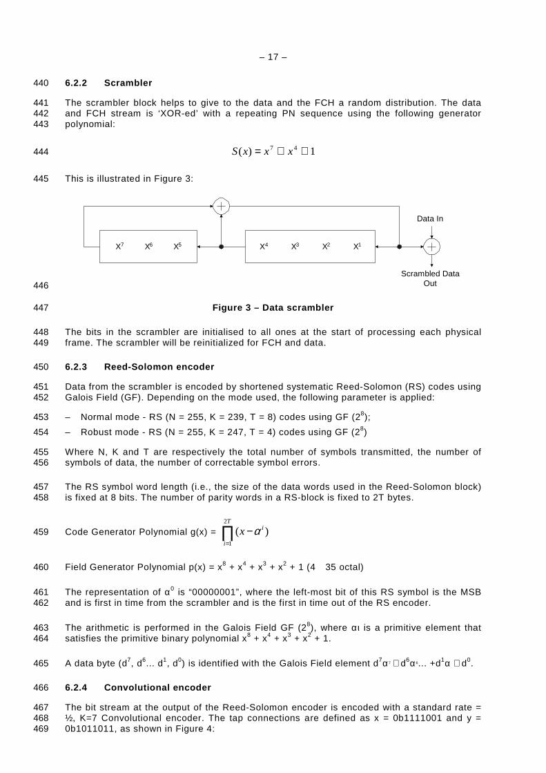
The scrambler block helps to give to the data and the FCH a random distribution. The data 441 and FCH stream is ‘XOR-ed’ with a repeating PN sequence using the following generator 442 polynomial: 443
1)( 47 ⊕⊕= xxxS 444
This is illustrated in Figure 3: 445
X7 X6 X5 X4 X3 X2 X1
Data In
Scrambled DataOut 446
Figure 3 – Data scrambler 447
The bits in the scrambler are initialised to all ones at the start of processing each physical 448 frame. The scrambler will be reinitialized for FCH and data. 449
6.2.3 Reed-Solomon encoder 450
Data from the scrambler is encoded by shortened systematic Reed-Solomon (RS) codes using 451 Galois Field (GF). Depending on the mode used, the following parameter is applied: 452
– Normal mode - RS (N = 255, K = 239, T = 8) codes using GF (28); 453
– Robust mode - RS (N = 255, K = 247, T = 4) codes using GF (28) 454
Where N, K and T are respectively the total number of symbols transmitted, the number of 455 symbols of data, the number of correctable symbol errors. 456
The RS symbol word length (i.e., the size of the data words used in the Reed-Solomon block) 457 is fixed at 8 bits. The number of parity words in a RS-block is fixed to 2T bytes. 458
Code Generator Polynomial g(x) = ∏=
−T
i
ix2
1
)( α 459
Field Generator Polynomial p(x) = x8 + x4 + x3 + x2 + 1 (4 35 octal) 460
The representation of α0 is “00000001”, where the left-most bit of this RS symbol is the MSB 461 and is first in time from the scrambler and is the first in time out of the RS encoder. 462
The arithmetic is performed in the Galois Field GF (28), where αι is a primitive element that 463 satisfies the primitive binary polynomial x8 + x4 + x3 + x2 + 1. 464
A data byte (d7, d6... d1, d0) is identified with the Galois Field element d7α7 + d6α6... +d1α + d0. 465
6.2.4 Convolutional encoder 466
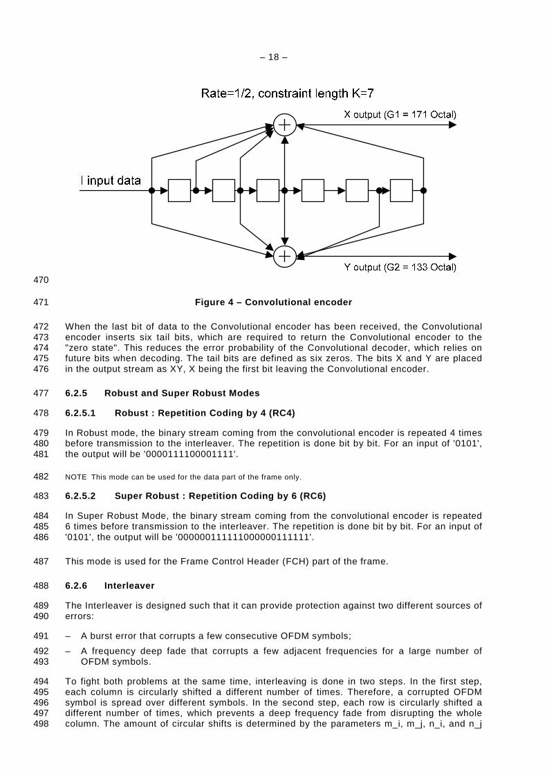
The bit stream at the output of the Reed-Solomon encoder is encoded with a standard rate = 467 ½, K=7 Convolutional encoder. The tap connections are defined as x = 0b1111001 and y = 468 0b1011011, as shown in Figure 4: 469
– 18 –
470
Figure 4 – Convolutional encoder 471
When the last bit of data to the Convolutional encoder has been received, the Convolutional 472 encoder inserts six tail bits, which are required to return the Convolutional encoder to the 473 "zero state". This reduces the error probability of the Convolutional decoder, which relies on 474 future bits when decoding. The tail bits are defined as six zeros. The bits X and Y are placed 475 in the output stream as XY, X being the first bit leaving the Convolutional encoder. 476
6.2.5 Robust and Super Robust Modes 477
6.2.5.1 Robust : Repetition Coding by 4 (RC4) 478
In Robust mode, the binary stream coming from the convolutional encoder is repeated 4 times 479 before transmission to the interleaver. The repetition is done bit by bit. For an input of '0101', 480 the output will be '0000111100001111'. 481
NOTE This mode can be used for the data part of the frame only. 482
6.2.5.2 Super Robust : Repetition Coding by 6 (RC6) 483
In Super Robust Mode, the binary stream coming from the convolutional encoder is repeated 484 6 times before transmission to the interleaver. The repetition is done bit by bit. For an input of 485 '0101', the output will be '000000111111000000111111'. 486
This mode is used for the Frame Control Header (FCH) part of the frame. 487
6.2.6 Interleaver 488
The Interleaver is designed such that it can provide protection against two different sources of 489 errors: 490
– A burst error that corrupts a few consecutive OFDM symbols; 491
– A frequency deep fade that corrupts a few adjacent frequencies for a large number of 492 OFDM symbols. 493
To fight both problems at the same time, interleaving is done in two steps. In the first step, 494 each column is circularly shifted a different number of times. Therefore, a corrupted OFDM 495 symbol is spread over different symbols. In the second step, each row is circularly shifted a 496 different number of times, which prevents a deep frequency fade from disrupting the whole 497 column. The amount of circular shifts is determined by the parameters m_i, m_j, n_i, and n_j 498
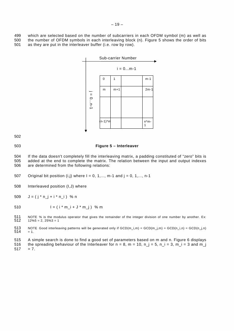
– 19 –
which are selected based on the number of subcarriers in each OFDM symbol (m) as well as 499 the number of OFDM symbols in each interleaving block (n). Figure 5 shows the order of bits 500 as they are put in the interleaver buffer (i.e. row by row). 501
502
Figure 5 – Interleaver 503
If the data doesn't completely fill the interleaving matrix, a padding constituted of “zero” bits is 504 added at the end to complete the matrix. The relation between the input and output indexes 505 are determined from the following relations: 506
Original bit position (i,j) where I = 0, 1,..., m-1 and j = 0, 1,..., n-1 507
Interleaved position (I,J) where 508
J = ( j * n_j + i * n_i ) % n 509
I = ( i * m_i + J * m_j ) % m 510
NOTE % is the modulus operator that gives the remainder of the integer division of one number by another. Ex: 511 12%5 = 2, 25%3 = 1 512
NOTE Good interleaving patterns will be generated only if GCD(m_i,m) = GCD(m_j,m) = GCD(n_i,n) = GCD(n_j,n) 513 = 1. 514
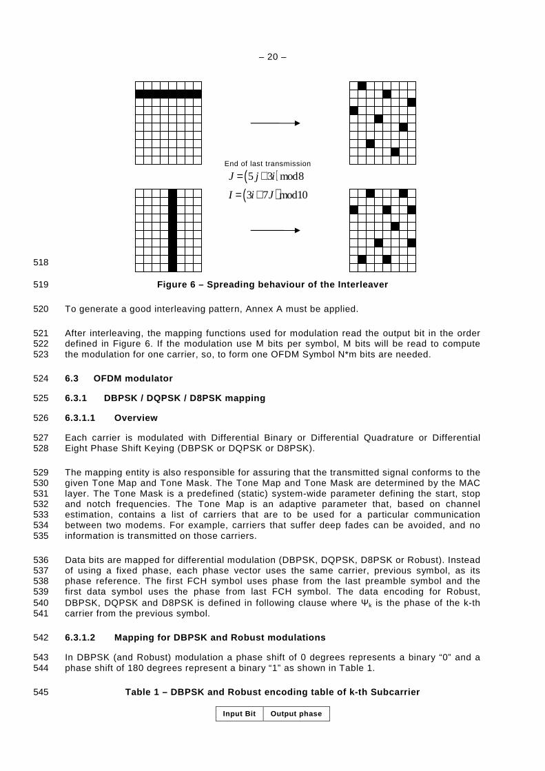
A simple search is done to find a good set of parameters based on m and n. Figure 6 displays 515 the spreading behaviour of the Interleaver for n = 8, m = 10, n_j = 5, n_i = 3, m_i = 3 and m_j 516 = 7. 517
Sub-carrier Number
i = 0...m-1
j = 0
...n-1
0 1 m-1
m m+1 2m-1
n*m-1
(n-1)*m
– 20 –
518
Figure 6 – Spreading behaviour of the Interleaver 519
To generate a good interleaving pattern, Annex A must be applied. 520
After interleaving, the mapping functions used for modulation read the output bit in the order 521 defined in Figure 6. If the modulation use M bits per symbol, M bits will be read to compute 522 the modulation for one carrier, so, to form one OFDM Symbol N*m bits are needed. 523
6.3 OFDM modulator 524
6.3.1 DBPSK / DQPSK / D8PSK mapping 525
6.3.1.1 Overview 526
Each carrier is modulated with Differential Binary or Differential Quadrature or Differential 527 Eight Phase Shift Keying (DBPSK or DQPSK or D8PSK). 528
The mapping entity is also responsible for assuring that the transmitted signal conforms to the 529 given Tone Map and Tone Mask. The Tone Map and Tone Mask are determined by the MAC 530 layer. The Tone Mask is a predefined (static) system-wide parameter defining the start, stop 531 and notch frequencies. The Tone Map is an adaptive parameter that, based on channel 532 estimation, contains a list of carriers that are to be used for a particular communication 533 between two modems. For example, carriers that suffer deep fades can be avoided, and no 534 information is transmitted on those carriers. 535
Data bits are mapped for differential modulation (DBPSK, DQPSK, D8PSK or Robust). Instead 536 of using a fixed phase, each phase vector uses the same carrier, previous symbol, as its 537 phase reference. The first FCH symbol uses phase from the last preamble symbol and the 538 first data symbol uses the phase from last FCH symbol. The data encoding for Robust, 539 DBPSK, DQPSK and D8PSK is defined in following clause where Ψk is the phase of the k-th 540 carrier from the previous symbol. 541
6.3.1.2 Mapping for DBPSK and Robust modulations 542
In DBPSK (and Robust) modulation a phase shift of 0 degrees represents a binary “0” and a 543 phase shift of 180 degrees represent a binary “1” as shown in Table 1. 544
Table 1 – DBPSK and Robust encoding table of k-th S ubcarrier 545
Input Bit Output phase
End of last transmission
( )( )5 3 mod8
3 7 mod10
J j i
I i J
= +
= +

– 21 –
Input Bit Output phase
0 Ψk
1 Ψk + π
Figure 7 shows the constellation diagram of the DBPSK and Robust modulation: 546
547
Figure 7 – DBPSK and Robust constellation diagram 548
6.3.1.3 Mapping for DQPSK modulation 549
In DQPSK a pair of 2 bits is mapped to 4 different output phases. The phase shifts of 0, 90, 550 180, and 270 degrees represent binary “00”, “01”, “11”, and “10”, respectively as shown in 551 Table 2. 552
Table 2 – DQPSK encoding table of k-th subcarrier 553
Input bit pattern (X,Y),
Y is first interleaver output Output phase
00 Ψk
01 Ψk + π/2
11 Ψk + π
10 Ψk + 3π/2
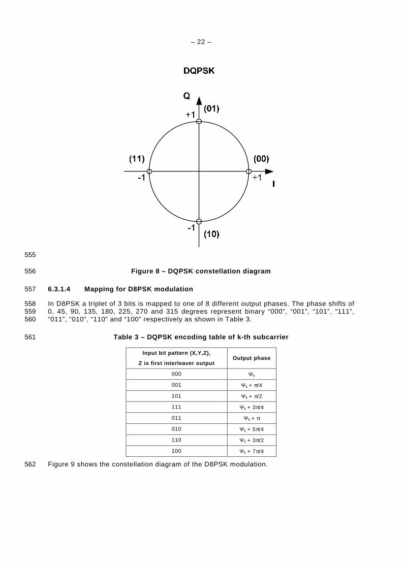
Figure 8 shows the constellation diagram of the DQPSK modulation. 554
– 22 –
555
Figure 8 – DQPSK constellation diagram 556
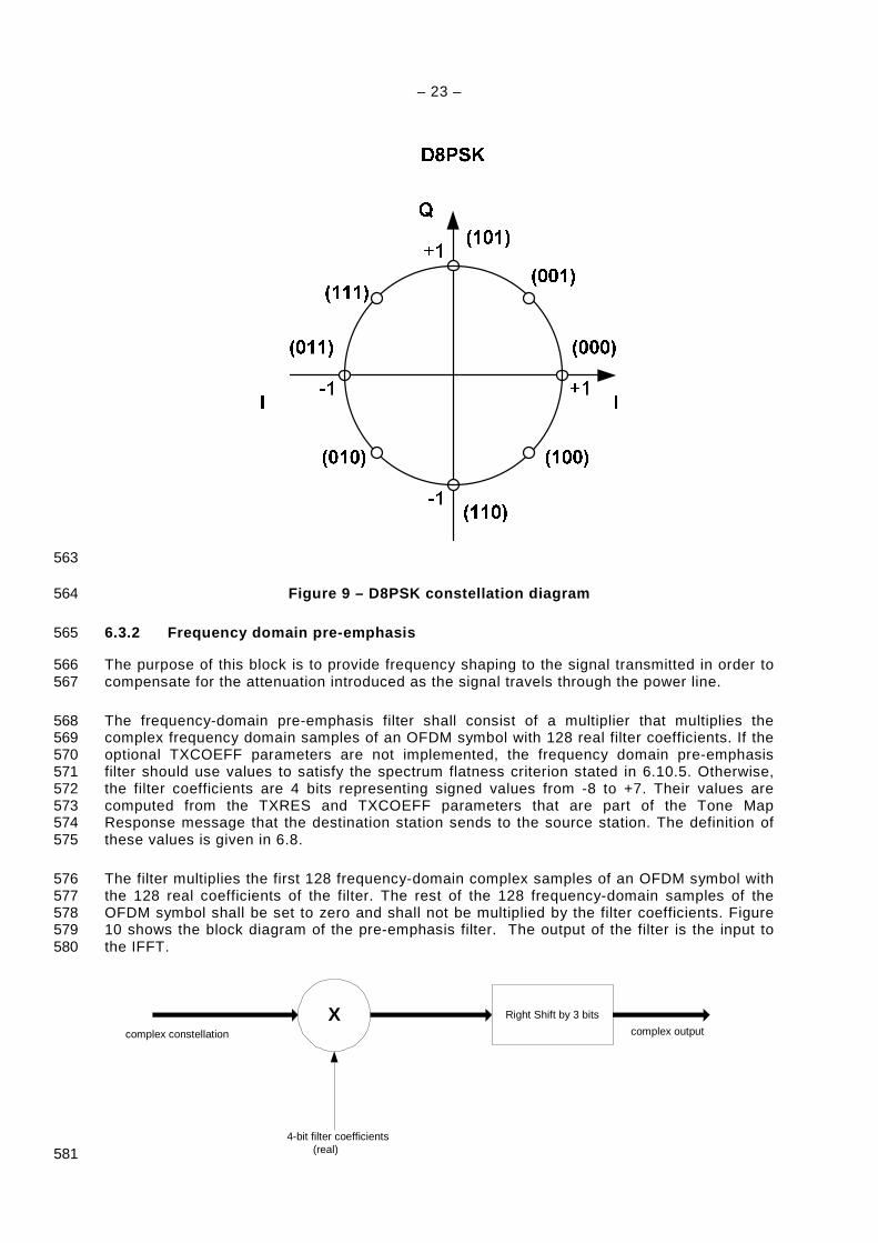
6.3.1.4 Mapping for D8PSK modulation 557
In D8PSK a triplet of 3 bits is mapped to one of 8 different output phases. The phase shifts of 558 0, 45, 90, 135, 180, 225, 270 and 315 degrees represent binary “000”, “001”, “101”, “111”, 559 “011”, “010”, “110” and “100” respectively as shown in Table 3. 560
Table 3 – DQPSK encoding table of k-th subcarrier 561
Input bit pattern (X,Y,Z),
Z is first interleaver output Output phase
000 Ψk
001 Ψk + π/4
101 Ψk + π/2
111 Ψk + 3π/4
011 Ψk + π
010 Ψk + 5π/4
110 Ψk + 3π/2
100 Ψk + 7π/4
Figure 9 shows the constellation diagram of the D8PSK modulation. 562
– 23 –
563
Figure 9 – D8PSK constellation diagram 564
6.3.2 Frequency domain pre-emphasis 565
The purpose of this block is to provide frequency shaping to the signal transmitted in order to 566 compensate for the attenuation introduced as the signal travels through the power line. 567
The frequency-domain pre-emphasis filter shall consist of a multiplier that multiplies the 568 complex frequency domain samples of an OFDM symbol with 128 real filter coefficients. If the 569 optional TXCOEFF parameters are not implemented, the frequency domain pre-emphasis 570 filter should use values to satisfy the spectrum flatness criterion stated in 6.10.5. Otherwise, 571 the filter coefficients are 4 bits representing signed values from -8 to +7. Their values are 572 computed from the TXRES and TXCOEFF parameters that are part of the Tone Map 573 Response message that the destination station sends to the source station. The definition of 574 these values is given in 6.8. 575
The filter multiplies the first 128 frequency-domain complex samples of an OFDM symbol with 576 the 128 real coefficients of the filter. The rest of the 128 frequency-domain samples of the 577 OFDM symbol shall be set to zero and shall not be multiplied by the filter coefficients. Figure 578 10 shows the block diagram of the pre-emphasis filter. The output of the filter is the input to 579 the IFFT. 580
complex constellation
X Right Shift by 3 bits
complex output
4-bit filter coefficients(real) 581
– 24 –
Figure 10 – Block diagram of the pre-emphasis filte r 582
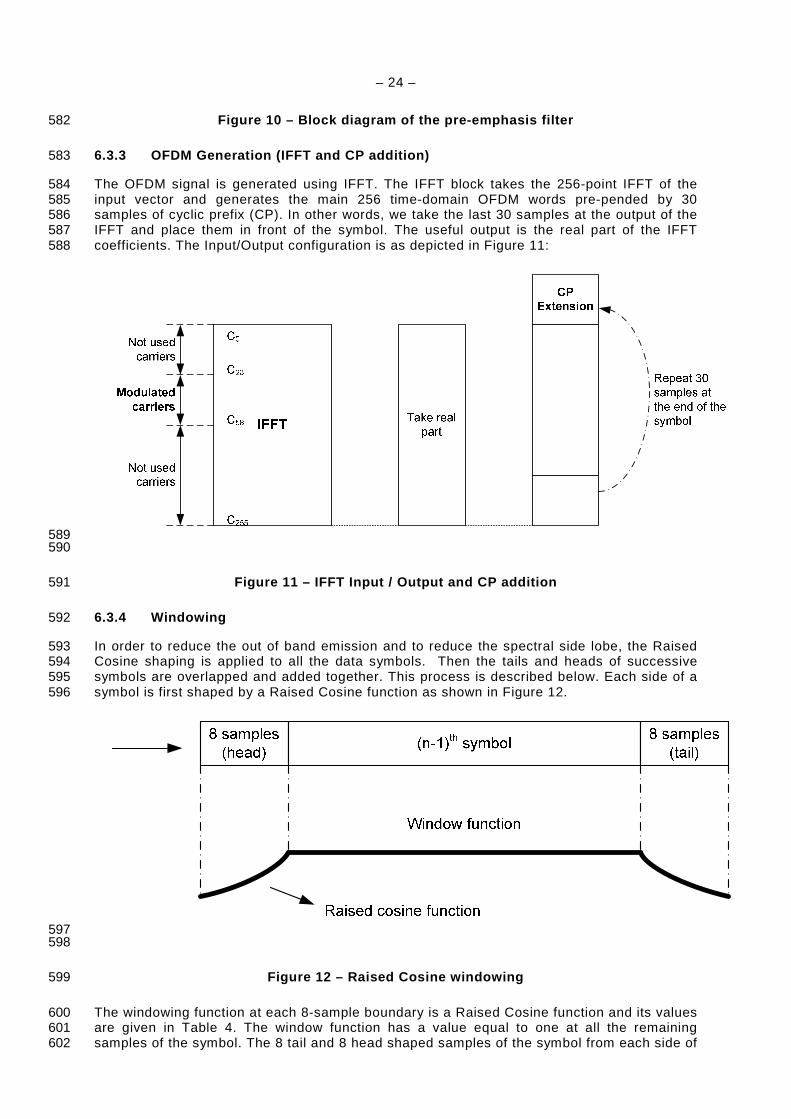
6.3.3 OFDM Generation (IFFT and CP addition) 583
The OFDM signal is generated using IFFT. The IFFT block takes the 256-point IFFT of the 584 input vector and generates the main 256 time-domain OFDM words pre-pended by 30 585 samples of cyclic prefix (CP). In other words, we take the last 30 samples at the output of the 586 IFFT and place them in front of the symbol. The useful output is the real part of the IFFT 587 coefficients. The Input/Output configuration is as depicted in Figure 11: 588
589 590
Figure 11 – IFFT Input / Output and CP addition 591
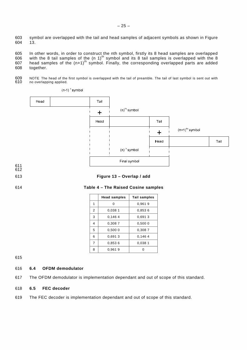
6.3.4 Windowing 592
In order to reduce the out of band emission and to reduce the spectral side lobe, the Raised 593 Cosine shaping is applied to all the data symbols. Then the tails and heads of successive 594 symbols are overlapped and added together. This process is described below. Each side of a 595 symbol is first shaped by a Raised Cosine function as shown in Figure 12. 596
597 598
Figure 12 – Raised Cosine windowing 599
The windowing function at each 8-sample boundary is a Raised Cosine function and its values 600 are given in Table 4. The window function has a value equal to one at all the remaining 601 samples of the symbol. The 8 tail and 8 head shaped samples of the symbol from each side of 602
– 25 –
symbol are overlapped with the tail and head samples of adjacent symbols as shown in Figure 603 13. 604
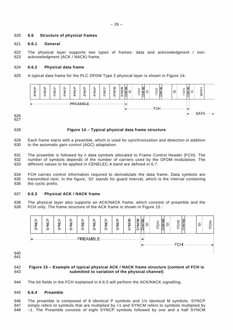
In other words, in order to construct the nth symbol, firstly its 8 head samples are overlapped 605 with the 8 tail samples of the (n 1)th symbol and its 8 tail samples is overlapped with the 8 606 head samples of the (n+1)th symbol. Finally, the corresponding overlapped parts are added 607 together. 608
NOTE The head of the first symbol is overlapped with the tail of preamble. The tail of last symbol is sent out with 609 no overlapping applied. 610
611 612
Figure 13 – Overlap / add 613
Table 4 – The Raised Cosine samples 614
Head samples Tail samples
1 0 0,961 9
2 0,038 1 0,853 6
3 0,146 4 0,691 3
4 0,308 7 0,500 0
5 0,500 0 0,308 7
6 0,691 3 0,146 4
7 0,853 6 0,038 1
8 0,961 9 0
615
6.4 OFDM demodulator 616
The OFDM demodulator is implementation dependant and out of scope of this standard. 617
6.5 FEC decoder 618
The FEC decoder is implementation dependant and out of scope of this standard. 619
– 26 –
6.6 Structure of physical frames 620
6.6.1 General 621
The physical layer supports two types of frames: data and acknowledgment / non-622 acknowledgment (ACK / NACK) frame. 623
6.6.2 Physical data frame 624
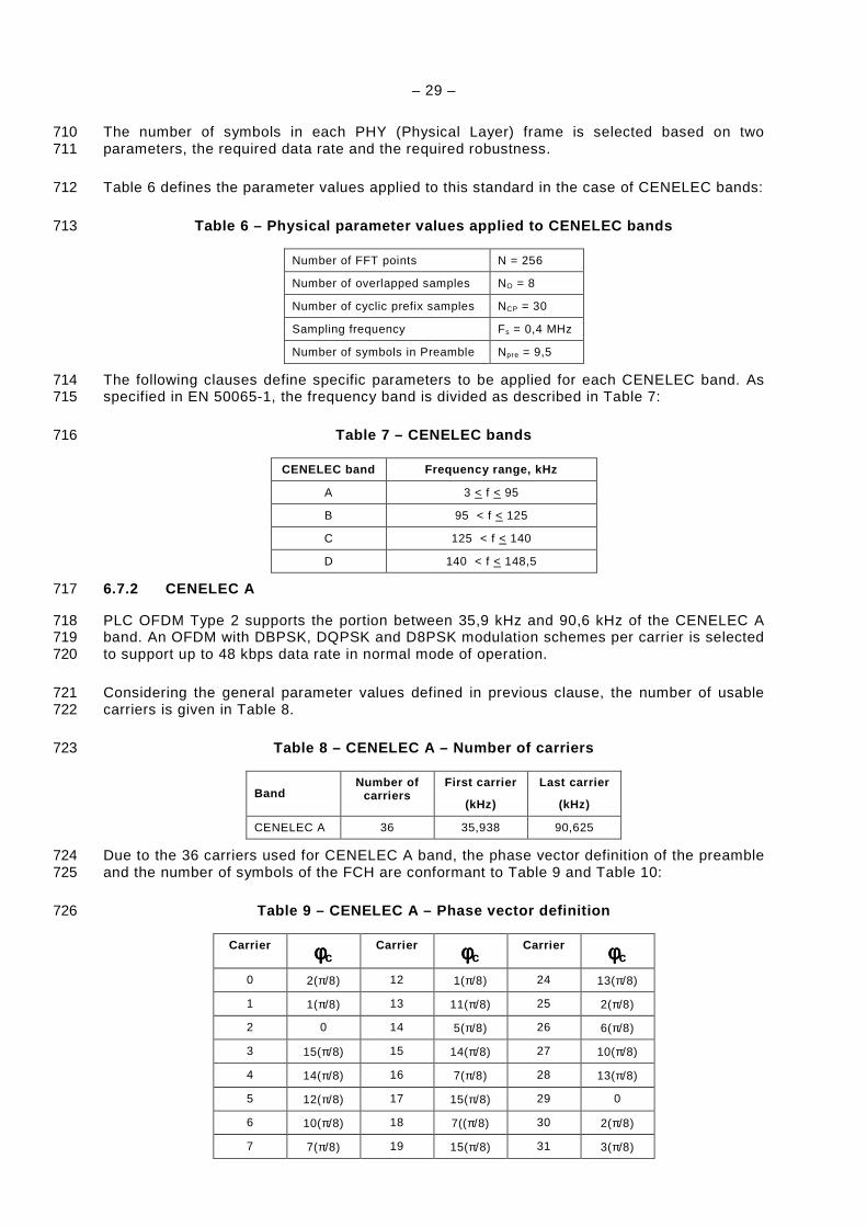
A typical data frame for the PLC OFDM Type 2 physical layer is shown in Figure 14: 625
626 627
Figure 14 – Typical physical data frame structure 628
Each frame starts with a preamble, which is used for synchronization and detection in addition 629 to the automatic gain control (AGC) adaptation. 630
The preamble is followed by n data symbols allocated to Frame Control Header (FCH). The 631 number of symbols depends of the number of carriers used by the OFDM modulation. The 632 different values to be applied in CENELEC A band are defined in 6.7. 633
FCH carries control information required to demodulate the data frame. Data symbols are 634 transmitted next. In the figure, ‘GI’ stands for guard interval, which is the interval containing 635 the cyclic prefix. 636
6.6.3 Physical ACK / NACK frame 637
The physical layer also supports an ACK/NACK frame, which consists of preamble and the 638 FCH only. The frame structure of the ACK frame is shown in Figure 15 : 639
640 641
Figure 15 – Example of typical physical ACK / NACK frame structure (content of FCH is 642 submitted to variation of the physical channel) 643
The bit fields in the FCH explained in 6.6.5 will perform the ACK/NACK signalling. 644
6.6.4 Preamble 645
The preamble is composed of 8 identical P symbols and 1½ identical M symbols. SYNCP 646 simply refers to symbols that are multiplied by +1 and SYNCM refers to symbols multiplied by 647 –1. The Preamble consists of eight SYNCP symbols followed by one and a half SYNCM 648

– 27 –
symbols with no cyclic prefix between adjacent symbols. The first symbol includes raised 649 cosine shaping on the leading points. The last half symbol also includes raised cosine 650 shaping on the trailing points. Each of the P and M symbols contain 256 samples and they are 651 pre-stored in the transmitter and transmitted right before the data symbols. The P symbols are 652 used for AGC adaptation, symbol synchronization, channel estimation and initial phase 653 reference estimation. The M symbols are identical to P symbols except that all the carriers are 654 π phase shifted. 655
At the receiver, the phase distance between symbol P and symbol M waveforms is used for 656 frame synchronization. A P symbol is generated by creating n equally spaced carriers with the 657
phase of each carrier given by the phase vector (φc). The phase vector definition depends to 658 the number of carriers used. Clause 6.7 describes in detail the different values in case of 659 CENELEC A band. 660
One way to generate this signal is to start in the frequency domain and create n complex 661
carriers with the initial phase φc (where n depends to the number of carriers used). 662
6.6.5 Frame Control Header (FCH) 663
Immediately after the preamble pattern, the next data symbols are reserved for the frame 664 control header (FCH). Depending of the number of carriers used, the number of symbols 665 varies as defined in next clause. 666
The FCH is a data structure transmitted at the beginning of each data frame and contains 667 information regarding the current frame. It has information about the type of frame. Table 5 668 defines the fields of the FCH : 669
Table 5 – FCH bit fields 670
Field Byte Bit number
Bits Definition
PDC 0 7-0 8 Phase detection counter
see §6.9 AC phase detection
MOD 1 7-6 2 Modulation type:
0 – Robust,
1 – DBPSK,
2 – DQPSK,
3 – D8PSK
FL 1 5-0 6 The frame data length expressed in OFDM symbols (equal to FL*4)
TM[0:7] 2 7-0 8 TM[0:7] – Tone map
see §6.7 for binding between tone map bits and carriers
TM[8] 3 7 1 TM[8] – Tone map
DT 3 6-4 3 Delimiter type:
000: Start of frame with no response expected;
001: Start of frame with response expected;
010: Positive acknowledgement (ACK)
011: Negative acknowledgement (NACK)
100-111: Reserved
FCCS 3 3-0 4 Frame Control Check Sequence (CRC5)
4 7 1

– 28 –
Field Byte Bit number
Bits Definition
Total bits 33
The FCH shall use the default tone map (all allowed subcarriers). 671
A 5-bit Frame Control Check Sequence (CRC5) is used for error detection in the FCH. The 672 CRC5 is computed as a function of the 28-bit sequence. It is calculated using the following 673 standard generator polynomial of degree 5: 674
1)( 25 ++= xxxG 675
The CRC5 is the remainder of the division of the FCH polynomial by the generator polynomial. 676 For this calculation, the CRC should be initialized to all ones and the remainder of the division 677 should be inverted (XORed with 11111b). It should be noted that as the CRC5 is not as robust 678 as CRC8, guard bands may be used to make it more robust (such as using reserved values 679 and checking the validity of combination of received values). 680
NOTE Please note the packing of CRC5 in the FCH as the CRC MSB is packed on the 4th Byte. Please note that 681 the FCH scrambling is performed after the addition of CRC5. 682
6.7 System fundamental parameters depending CENELEC bands 683
6.7.1 General specification applied to CENELEC band s 684
PLC OFDM Type 2 supports the allowed frequencies defined in EN 50065-1. 685
The DBPSK, DQPSK and D8PSK modulation for each carrier makes the receiver design 686 significantly simpler since no tracking circuitry is required at the receiver for coherently 687 detecting the phase of each carrier. Instead, the phases of carriers in the adjacent symbol are 688 taken as reference for detecting the phases of the carriers in the current symbol. 689
There is potential to use this standard to support communication in frequencies up to 148,5 690 kHz. As a result, the sampling frequency at the transmitter and the receiver is selected to be 691 0,4 MHz in order to provide some margin above the Nyquist frequency for signal filtering in 692 the transmitter (for PSD shaping to remove the signal images) and at the receiver (for band 693 selection and signal enhancement). 694
The maximum number of carriers that can be used is selected to be 128, resulting in an IFFT 695 size of 256. This results in a frequency spacing between the OFDM carriers equal to 696 1,5625 kHz * (Fs / N), where Fs is the sampling frequency and N is the IFFT size. Note that 697 imperfections such as sampling clock frequency variation may cause Inter Carrier Interference 698 (ICI). In practice, the ICI caused by a typical sampling frequency variation of about 2 % of the 699 frequency spacing is negligible. In other word, considering ±25 ppm sampling frequency 700 variation in the transmitter and receiver clocks, the drift of the carriers is approximately equal 701 to 8Hz that is approximately 0,5 % of the selected frequency spacing. 702
The system works in two different modes namely Normal and Robust modes. 703
In Normal mode, the FEC encoder is composed of a Reed-Solomon encoder (with parity 16 704 bytes) and a Convolutional encoder. 705
In Robust mode the FEC encoder is composed of a Reed-Solomon (parity 8 bytes) and a 706 Convolutional encoders followed by a Repetition Code (RC). The RC coder repeats each bit 707 four times making the system more robust to channel impairments. This of course will reduce 708 the throughput by about factor of 4. 709
– 29 –
The number of symbols in each PHY (Physical Layer) frame is selected based on two 710 parameters, the required data rate and the required robustness. 711
Table 6 defines the parameter values applied to this standard in the case of CENELEC bands: 712
Table 6 – Physical parameter values applied to CENE LEC bands 713
Number of FFT points N = 256
Number of overlapped samples NO = 8
Number of cyclic prefix samples NCP = 30
Sampling frequency Fs = 0,4 MHz
Number of symbols in Preamble Npre = 9,5
The following clauses define specific parameters to be applied for each CENELEC band. As 714 specified in EN 50065-1, the frequency band is divided as described in Table 7: 715
Table 7 – CENELEC bands 716
CENELEC band Frequency range, kHz
A 3 < f < 95
B 95 < f < 125
C 125 < f < 140
D 140 < f < 148,5
6.7.2 CENELEC A 717
PLC OFDM Type 2 supports the portion between 35,9 kHz and 90,6 kHz of the CENELEC A 718 band. An OFDM with DBPSK, DQPSK and D8PSK modulation schemes per carrier is selected 719 to support up to 48 kbps data rate in normal mode of operation. 720
Considering the general parameter values defined in previous clause, the number of usable 721 carriers is given in Table 8. 722
Table 8 – CENELEC A – Number of carriers 723
Band Number of
carriers First carrier
(kHz)
Last carrier
(kHz)
CENELEC A 36 35,938 90,625
Due to the 36 carriers used for CENELEC A band, the phase vector definition of the preamble 724 and the number of symbols of the FCH are conformant to Table 9 and Table 10: 725
Table 9 – CENELEC A – Phase vector definition 726
Carrier φφφφc Carrier φφφφc Carrier φφφφc
0 2(π/8) 12 1(π/8) 24 13(π/8)
1 1(π/8) 13 11(π/8) 25 2(π/8)
2 0 14 5(π/8) 26 6(π/8)
3 15(π/8) 15 14(π/8) 27 10(π/8)
4 14(π/8) 16 7(π/8) 28 13(π/8)
5 12(π/8) 17 15(π/8) 29 0
6 10(π/8) 18 7((π/8) 30 2(π/8)
7 7(π/8) 19 15(π/8) 31 3(π/8)
– 30 –
Carrier φφφφc Carrier φφφφc Carrier φφφφc
8 3(π/8) 20 6(π/8) 32 5(π/8)
9 15(π/8) 21 13(π/8) 33 6(π/8)
10 11(π/8) 22 2(π/8) 34 7(π/8)
11 6(π/8) 23 8(π/8) 35 7(π/8)
Table 10 – CENELEC A - Number of FCH symbols 727
Number of FCH symbols, N FCH
CENELEC A 13
Given the FCH data length is 33 bits, there are 13 FCH symbols required. This can be 728 calculated using: 729
Number of FCH Symbols = ceiling (((N_FCH_bits + 6) x 2 x 6)/36) = ceiling ((39 x 2 x 6)/36) = 730 13. 731
NOTE Ceiling(x) = is the smallest integer not less than x. 732
The number of symbols, Reed-Solomon block sizes, and data rate associated with 36 carriers 733 is tabulated in Table 11 and Table 12. Table 13 shows the data rate including the data 734 transmitted in FCH. To calculate the data rate, it is assumed that the packets are continuously 735 transmitted with no inter-frame time gap. 736
Table 11 – CENELEC A – RS block size for various mo dulations 737
CENELEC A RS block size (Out/In) per modulation typ e, bytes
Number of symbols D8PSK, P16 1) DQPSK, P16 1) DBPSK, P16 1) Robust, P8 2)
12 (80/64) (53/37) (26/10) N/A
20 (134/118) (89/73) (44/28) N/A
32 (215/199) (143/127) (71/55) N/A
40 N/A (179/163) (89/73) (21/13)
52 N/A (233/217) (116/100) (28/20)
56 N/A (251/235) (125/109) (30/22)
112 N/A N/A (251/235) (62/54)
252 N/A N/A N/A (141/133)
1) P16 is Reed-Solomon with 16 bit parity
2) P8 is Reed-Solomon with 8 bit parity
NOTE N/A means not applicable and the reason is that the corresponding number of symbols specified results in RS encoder block length that exceeds the maximum allowable limit of 255.
Table 12 – CENELEC A – Data rate for various modula tions (excluding FCH) 738
CENELEC A Data rate per modulation type, bps
Number of Symbols D8PSK, P16 1) DQPSK, P16 1) DBPSK, P16 1) Robust, P8 2)
12 21 829 12 103 3 271 N/
20 32 534 19 456 7 462 N/A
32 42 618 26 489 11 471 N/A
40 N/A 29 693 13 298 2 423
52 N/A 33 221 15 309 3 121

– 31 –
CENELEC A Data rate per modulation type, bps
Number of Symbols D8PSK, P16 1) DQPSK, P16 1) DBPSK, P16 1) Robust, P8 2)
56 N/A 34 160 15 844 3 257
112 N/A N/A 20 009 4 647
252 N/A N/A N/A 5 592
1) P16 is Reed-Solomon with 16 bit parity
2) P8 is Reed-Solomon with 8 bit parity
NOTE N/A means not applicable and the reason is that the corresponding number of symbols specified results in RS encoder block length that exceeds the maximum allowable limit of 255.
Table 13 – CENELEC A – Data rate for various modula tions (including FCH) 739
CENELEC A Data rate per modulation type, bps
Number of Symbols D8PSK, P16 1) DQPSK, P16 1) DBPSK, P16 1) Robust, P8 2)
12 23 235 13 453 4 620 N/A
20 33 672 20 556 8 562 N/A
32 43 501 27 349 12 332 N/A
40 N/A 30 445 14 049 3 192
52 N/A 33 853 15 941 3 765
56 N/A 34 759 16 444 3 867
112 N/A N/A 20 360 5 002
252 N/A N/A N/A 5 765
1) P16 is Reed-Solomon with 16 bit parity
2) P8 is Reed-Solomon with 8 bit parity
NOTE N/A means not applicable and the reason is that the corresponding number of symbols specified results in RS encoder block length that exceeds the maximum allowable limit of 255.
The data rate is calculated based on the number of symbols per PHY frame (NS), the number 740 of carriers per symbol (Ncarr) and the number of parity bits added by FEC blocks. 741
As an example, consider the system in the CENELEC A band working in Robust mode with 40 742 symbols of data. The total number of bits carried by the whole physical frame is equal to: 743
Total_No_Bits = NS x Ncarr = 40 x 36 = 1 440 bits 744
The number of bits required at the input of the Robust encoder is given by: 745
No_Bits_Robust = 1 440 x RobustRate = 1 440 x ¼ = 360 bits 746
NOTE Due to the fact that the Robust mode reduces the throughput by about factor 4, the rate is also reduced by 747 about factor 4. 748
Considering the fact that the convolutional encoder has a rate equal to ½ (CCRate = ½) and 749 also consider adding CCZerotail = 6 bits of zeros to terminate the states of the encoder to all 750 zero states then the maximum number of symbols at the output of the Reed-Solomon encoder 751 (MAXRSbytes) is equal to: 752
MAXRSbytes = floor((No_Bits_Robust x CCRate - CCZeroTail)/8) = floor ((360 x ½ - 6)/8) = 21 753
– 32 –
NOTE floor(x) is the largest integer not greater than x 754
According for eight symbols associated with the parity bits (in Robust mode), we obtain: 755
DataLength = (21 - ParityLength) x 8 = 104 bits 756
These 104 bits are carried within the duration of a physical frame. The duration of a physical 757 frame is calculated by the following formula: 758
TFrame = ((NS+NFCH) x (NCP + N - NO) + (Npre x N))/Fs 759
Where: 760
– NS is the number of symbols to transmit; 761
– Npre is the number of symbols in the preamble; 762
– N is the FFT length; 763
– NO is the number of samples overlapped at each side of one symbol; 764
– NCP is the number of samples in the cyclic prefix; 765
– NFCH is the number of symbols in the FCH; 766
– Fs is the sampling frequency (in Hz). 767
With the actual values of the parameters the physical frame duration is equal to: 768
TFrame = ((40+13) x (30 + 256 - 8) + (9.5 x 256))/ 400 000 = 0,043 s. 769
Therefore the data rate is: 770
Data rate = 104 / 0.042 ~ 2,4 kbps. 771
6.8 Adaptive tone mapping & transmit power control 772
6.8.1 General 773
PLC OFDM Type 2 shall estimate the SNR of the received signal sub-carriers (tones) and 774 adaptively select the usable tones, the optimum modulation and coding type (including 775 DBPSK, DQPSK, D8PSK and the Robust mode) to ensure reliable communication over the 776 power line channel. It shall also specify what power level the remote transmitter shall use and 777 what gain values it should apply for the various sections of the spectrum. The per-carrier 778 quality measurement enables the system to adaptively avoid transmitting data on sub-carriers 779 with poor quality. Using a tone map indexing system, where the index is passed from receiver 780 to transmitter and vice versa, allows the receiver to adaptively select which sub-carriers will 781 be used for transmission and which ones will be used to send dummy data that the receiver 782 will ignore. 783
The goal of the adaptive tone mapping is to allow the PLC OFDM Type 2 receiver to achieve 784 the greatest possible throughput under the given channel conditions between the transmitter 785 and the receiver. In order to accomplish this goal, the receiver shall inform the remote 786 transmitter which tones it should use to send data bits on, and which tones it should use to 787 send dummy data bits that the receiver shall ignore. The receiver shall also inform the remote 788 transmitter how much amplification or attenuation it should apply to each of the tones. 789
The transmitter may request the receiver to estimate a channel condition by setting the TMR 790 bit of the Segment Control header of the MAC layer, as described in 7.3.3.2.2. 791
The receiver has to estimate this particular communication link between the two points and 792 choose optimal PHY parameters. This information will be sent back to the originator as a 793

– 33 –
Tone Map Response. Note that for broadcast always the Robust mode will be used. The other 794 modulation schemes are used for point-to-point or multi-point. 795
6.8.2 PN Modulating un-used subcarriers 796
The mapping function for DBPSK, DQPSK, D8PSK and Robust must obey the Tone Mask, 797 thus carriers that are masked are not assigned phase symbols, and the amplitude is zero. 798 When the modulation type is DBPSK, DQPSK or D8PSK the mapping function also obeys the 799 Tone Map. When a carrier is encountered on which no information is to be transmitted, the 800 mapping function substitutes a binary value from a Pseudo Noise (PN) sequence. The binary 801 value shall be used as the value for both bits in the case of DQPSK and for 3 bits for D8PSK. 802
The PN sequence shall be generated using the same generator polynomial introduced in 803 6.2.2. The bits in the PN sequence generator shall all be initialized to ones at the start of 804 processing each frame and sequenced to the next value after every mapped, unmapped or 805 masked carrier. The first value of the PN sequence (the output when all bits are initialized to 806 ones) corresponds to carrier number “0” of the first OFDM symbol of each frame and the 37th 807 value corresponds to carrier number “0” of the second OFDM symbol. 808
6.9 AC phase detection 809
This is a basic approach to detect AC phase associated to a device, however the optimal 810 design would be dependent on the particular network topology. This information is mainly 811 useful at system level in order to check for unexpected losses on the distribution line and 812 must be stored locally. 813
Three phases on the mains are sinusoidal waveforms with a phase shift of 120° from each 814 other where each half cycle is equal to 10 ms at 50 Hz and 8,3 ms at 60 Hz. A zero-crossing 815 detector delivers an output pulse based on the signal transition through zero volt of a 50/60 816 Hz sinusoidal on the power line, and is used to synchronize a Tx-device and an Rx-device. 817 The Tx-device generates a time stamp based on an internal counter at the instant a packet 818 shall be transmitted. The receiver provides its own time stamp, and the difference between 819 the Tx-device and the Rx-device time stamps provides the phase difference. The procedure to 820 achieve the phase difference between transmitter and receiver is as follows. 821
a) All devices shall have internal timers, which are synchronized to zero-crossing detector. 822
b) All devices shall have a zero-crossing detector that delivers an output pulse such that the 823 pulse width is 5 % of the total period. The characteristic of the zero-crossing detector is 824 shown in Figure 16: 825
826
Pulse WidthHalf Cycle =10 ms
Zero-Crossing detector
50 Hz
827 Figure 16 – Zero-crossing detector 828
c) An eight bits counter provides a time stamp placed on the FCH frame upon transmission of 829 payload. 830
d) Upon detection of the FCH frame, the receiver shall compute the delay, which is the 831 difference between transmit counter (PDC) and receive counter. The phase differential 832 shall be computed shown below. 833
e) Phase differential = (Rx_counter - Tx_Counter) /3 834
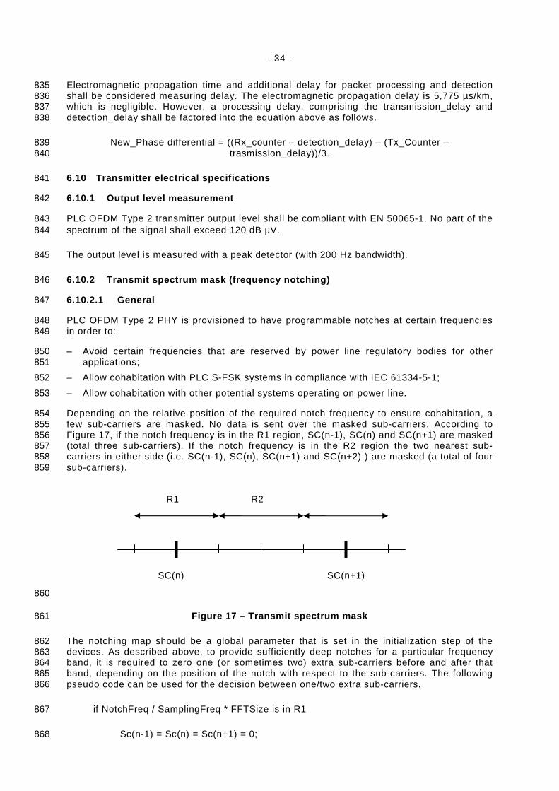
– 34 –
Electromagnetic propagation time and additional delay for packet processing and detection 835 shall be considered measuring delay. The electromagnetic propagation delay is 5,775 µs/km, 836 which is negligible. However, a processing delay, comprising the transmission_delay and 837 detection_delay shall be factored into the equation above as follows. 838
New_Phase differential = ((Rx_counter – detection_delay) – (Tx_Counter – 839 trasmission_delay))/3. 840
6.10 Transmitter electrical specifications 841
6.10.1 Output level measurement 842
PLC OFDM Type 2 transmitter output level shall be compliant with EN 50065-1. No part of the 843 spectrum of the signal shall exceed 120 dB µV. 844
The output level is measured with a peak detector (with 200 Hz bandwidth). 845
6.10.2 Transmit spectrum mask (frequency notching) 846
6.10.2.1 General 847
PLC OFDM Type 2 PHY is provisioned to have programmable notches at certain frequencies 848 in order to: 849
– Avoid certain frequencies that are reserved by power line regulatory bodies for other 850 applications; 851
– Allow cohabitation with PLC S-FSK systems in compliance with IEC 61334-5-1; 852
– Allow cohabitation with other potential systems operating on power line. 853
Depending on the relative position of the required notch frequency to ensure cohabitation, a 854 few sub-carriers are masked. No data is sent over the masked sub-carriers. According to 855 Figure 17, if the notch frequency is in the R1 region, SC(n-1), SC(n) and SC(n+1) are masked 856 (total three sub-carriers). If the notch frequency is in the R2 region the two nearest sub-857 carriers in either side (i.e. SC(n-1), SC(n), SC(n+1) and SC(n+2) ) are masked (a total of four 858 sub-carriers). 859
860
Figure 17 – Transmit spectrum mask 861
The notching map should be a global parameter that is set in the initialization step of the 862 devices. As described above, to provide sufficiently deep notches for a particular frequency 863 band, it is required to zero one (or sometimes two) extra sub-carriers before and after that 864 band, depending on the position of the notch with respect to the sub-carriers. The following 865 pseudo code can be used for the decision between one/two extra sub-carriers. 866
if NotchFreq / SamplingFreq * FFTSize is in R1 867
Sc(n-1) = Sc(n) = Sc(n+1) = 0; 868
SC(n) SC(n+1)
R1 R2
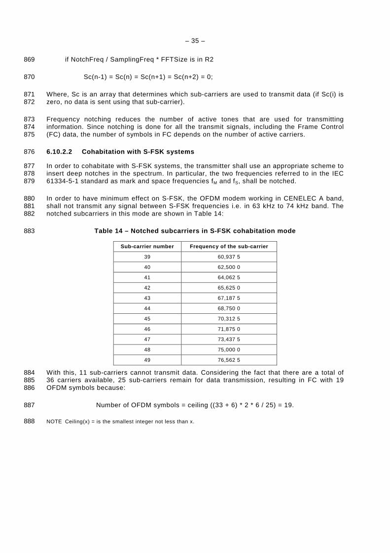
– 35 –
if NotchFreq / SamplingFreq * FFTSize is in R2 869
Sc(n-1) = Sc(n) = Sc(n+1) = Sc(n+2) = 0; 870
Where, Sc is an array that determines which sub-carriers are used to transmit data (if Sc(i) is 871 zero, no data is sent using that sub-carrier). 872
Frequency notching reduces the number of active tones that are used for transmitting 873 information. Since notching is done for all the transmit signals, including the Frame Control 874 (FC) data, the number of symbols in FC depends on the number of active carriers. 875
6.10.2.2 Cohabitation with S-FSK systems 876
In order to cohabitate with S-FSK systems, the transmitter shall use an appropriate scheme to 877 insert deep notches in the spectrum. In particular, the two frequencies referred to in the IEC 878 61334-5-1 standard as mark and space frequencies fM and fS, shall be notched. 879
In order to have minimum effect on S-FSK, the OFDM modem working in CENELEC A band, 880 shall not transmit any signal between S-FSK frequencies i.e. in 63 kHz to 74 kHz band. The 881 notched subcarriers in this mode are shown in Table 14: 882
Table 14 – Notched subcarriers in S-FSK cohabitatio n mode 883
Sub-carrier number Frequency of the sub-carrier
39 60,937 5
40 62,500 0
41 64,062 5
42 65,625 0
43 67,187 5
44 68,750 0
45 70,312 5
46 71,875 0
47 73,437 5
48 75,000 0
49 76,562 5
With this, 11 sub-carriers cannot transmit data. Considering the fact that there are a total of 884 36 carriers available, 25 sub-carriers remain for data transmission, resulting in FC with 19 885 OFDM symbols because: 886
Number of OFDM symbols = ceiling ((33 + 6) * 2 * 6 / 25) = 19. 887
NOTE Ceiling(x) = is the smallest integer not less than x. 888
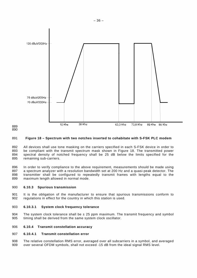
– 36 –
889 890
Figure 18 – Spectrum with two notches inserted to c ohabitate with S-FSK PLC modem 891
All devices shall use tone masking on the carriers specified in each S-FSK device in order to 892 be compliant with the transmit spectrum mask shown in Figure 18. The transmitted power 893 spectral density of notched frequency shall be 25 dB below the limits specified for the 894 remaining sub-carriers. 895
In order to verify compliance to the above requirement, measurements should be made using 896 a spectrum analyzer with a resolution bandwidth set at 200 Hz and a quasi-peak detector. The 897 transmitter shall be configured to repeatedly transmit frames with lengths equal to the 898 maximum length allowed in normal mode. 899
6.10.3 Spurious transmission 900
It is the obligation of the manufacturer to ensure that spurious transmissions conform to 901 regulations in effect for the country in which this station is used. 902
6.10.3.1 System clock frequency tolerance 903
The system clock tolerance shall be ± 25 ppm maximum. The transmit frequency and symbol 904 timing shall be derived from the same system clock oscillator. 905
6.10.4 Transmit constellation accuracy 906
6.10.4.1 Transmit constellation error 907
The relative constellation RMS error, averaged over all subcarriers in a symbol, and averaged 908 over several OFDM symbols, shall not exceed -15 dB from the ideal signal RMS level. 909

– 37 –
6.10.4.2 Transmit modulation accuracy test 910
The transmit modulation accuracy test shall be performed by instrumentation capable of 911 converting the transmitted signal into a stream of samples, using at least the sampling rate 912 applicable for the CENELEC A band, with sufficient accuracy in terms of amplitude, DC 913 offsets, and phase noise. The sampled signal shall be processed in a manner similar to an 914 actual receiver, according to the following steps, or an equivalent procedure. 915
An example is provided below: 916
a) Pass a sequence of 88 bytes all ones, representing a 12-symbol QPSK frame, through an 917 ideal floating point pseudo-transmitter, for example using matlab, and save the complex 918 IFFT input for each of the 12 data symbols as Aicexp[jΦ ic] , where i is the symbol number 919 and c is the carrier number corresponding to that symbol. 'i' will have values between 0 920 and 11 while c will be between 0 and 35. The ideal sub-transmitter should include all the 921 transmitter blocks specified in this standard, including Scrambler, RS encoder, 922 convolutional encoder, interleaver and mapper. 923
b) Next, use the transmitter under test to generate the same frame using the bits specified in 924 step a). 925
c) Connect the test equipment that will simulate the receiver directly to the transmitter to 926 detect start of frame. 927
d) Save all 12 data symbols of the frame. 928
e) Offline, apply a floating-point FFT on each symbol and store the complex values as 929 Bicexp[jθic] where i is the symbol number and c is the carrier number corresponding to that 930 symbol. 931
f) Compute the RMS error between the transmitted and ideal constellation points for each 932 symbol as the sum of the squared Euclidean distance between the two points over all the 933 carriers in the symbol: 934
error_rms i = 235
0
]exp[*]exp[* icjBicicjAicabsc
Θ−Φ∑=
935
Next compute the total RMS error as the sum of the RMS errors of the individual symbols: 936
total error rms = ∑=
11
0
_i
irmserror 937
Compute the RMS of each transmitted symbol as: 938
Tx_rms i = ∑=
35
0
2
c
Aic 939
And the total RMS for all transmitted symbols as: 940
total Tx rms = ∑=
11
0
_i
irmsTx 941
g) Total error RMS should satisfy the following equation: 942
20*log10 (total error rms / total Tx rms) < -15 dB 943
6.10.5 Transmitter Spectral Flatness 944
No individual carrier shall have average power outside of the range +/- 2 dB with respect to 945 the average power in all of the carriers. 946
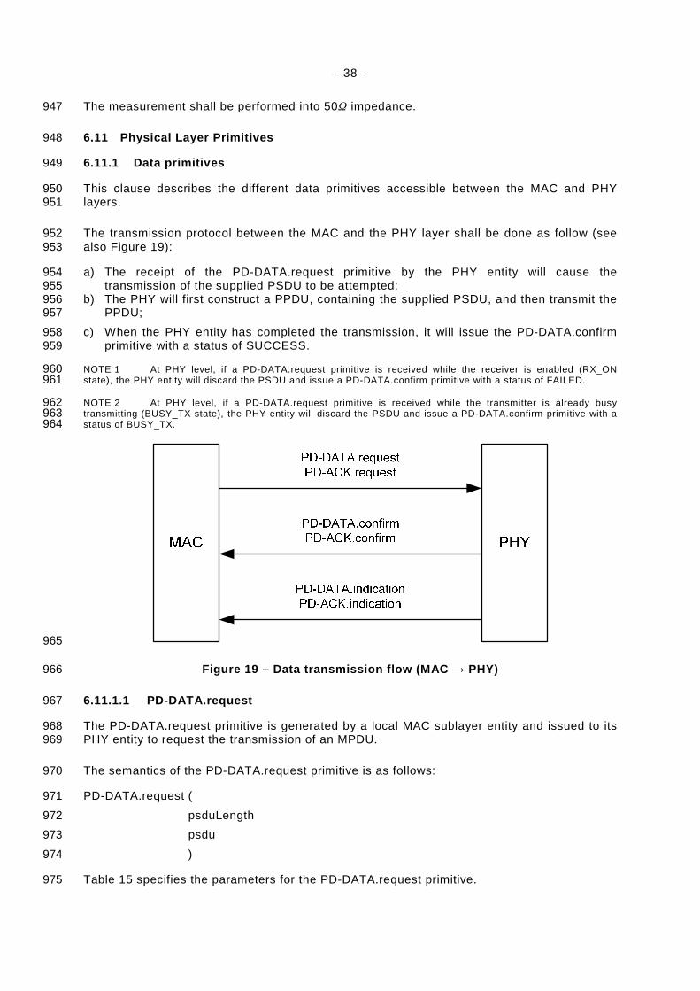
– 38 –
The measurement shall be performed into 50Ω impedance. 947
6.11 Physical Layer Primitives 948
6.11.1 Data primitives 949
This clause describes the different data primitives accessible between the MAC and PHY 950 layers. 951
The transmission protocol between the MAC and the PHY layer shall be done as follow (see 952 also Figure 19): 953
a) The receipt of the PD-DATA.request primitive by the PHY entity will cause the 954 transmission of the supplied PSDU to be attempted; 955
b) The PHY will first construct a PPDU, containing the supplied PSDU, and then transmit the 956 PPDU; 957
c) When the PHY entity has completed the transmission, it will issue the PD-DATA.confirm 958 primitive with a status of SUCCESS. 959
NOTE 1 At PHY level, if a PD-DATA.request primitive is received while the receiver is enabled (RX_ON 960 state), the PHY entity will discard the PSDU and issue a PD-DATA.confirm primitive with a status of FAILED. 961
NOTE 2 At PHY level, if a PD-DATA.request primitive is received while the transmitter is already busy 962 transmitting (BUSY_TX state), the PHY entity will discard the PSDU and issue a PD-DATA.confirm primitive with a 963 status of BUSY_TX. 964
965
Figure 19 – Data transmission flow (MAC → PHY) 966
6.11.1.1 PD-DATA.request 967
The PD-DATA.request primitive is generated by a local MAC sublayer entity and issued to its 968 PHY entity to request the transmission of an MPDU. 969
The semantics of the PD-DATA.request primitive is as follows: 970
PD-DATA.request ( 971
psduLength 972
psdu 973
) 974
Table 15 specifies the parameters for the PD-DATA.request primitive. 975
– 39 –
Table 15 – PD-DATA.request primitive 976
Name Type Valid Range Description
psduLength Integer 0 to 400 The number of bytes contained in the PSDU to be transmitted by the PHY entity.
psdu Bytes ------ The set of bytes forming the PSDU request to transmit by the PHY entity.
6.11.1.2 PD-DATA.confirm 977
The PD-DATA.confirm primitive confirms the end of the transmission of an MPDU (i.e., PSDU) 978 from a local PHY entity to a peer PHY entity. 979
The semantics of the PD-DATA.confirm primitive is as follows: 980
PD-DATA.confirm ( 981
status 982
) 983
Table 16 specifies the parameters for the PD-DATA.confirm primitive. 984
Table 16 – PD-DATA.confirm primitive 985
Name Type Valid Range Description
Status Enumeration SUCCESS (0), FAILED (1)
The result of the request to transmit a packet.
6.11.1.3 PD-DATA.indication 986
The PD-DATA.indication primitive indicates the transfer of an MPDU (i.e., PSDU) from the 987 PHY to the local MAC sublayer entity. 988
The semantics of the PD-DATA.indication primitive is as follows: 989
PD-DATA.indication ( 990
psduLength, 991
psdu, 992
ppduLinkQuality 993
) 994
Table 17 specifies the parameters for the PD-DATA.indication primitive. 995
Table 17 – PD-DATA.indication primitive 996
Name Type Valid Range Description
psduLength Integer Maximum 400 The number of bytes contained in the PSDU received by the PHY entity.
Psdu Bytes ------- The set of bytes forming the PSDU received by the PHY entity.
ppduLinkQuality Integer 0 to 255 Link Quality Indicator (LQI) value measured during reception of the PPDU
6.11.1.4 PD-ACK.request 997
The PD-ACK.request primitive demands the MAC sublayer entity send an ACK frame to the 998 PHY entity.The semantics of the PD-ACK.request primitive is as follows: 999
PD-ACK.request ( 1000
– 40 –
FCH 1001
) 1002
Table 18 specifies the parameter for the PD-ACK.request primitive. 1003
Table 18 – PD-ACK.request primitive 1004
Name Type Valid Range Description
FCH Structure See 6.6.5 MAC layer provides all Frame Control Header parameters to construct FCH frame for ACK.
6.11.1.5 PD-ACK.confirm 1005
The PD-ACK.confirm confirms the end of the transmission of an ACK packet. 1006
The semantics of the PD-ACK.confirm primitive is as follows: 1007
PD-ACK.confirm ( 1008
Status 1009
) 1010
Table 19 specifies the parameter for the PD-ACK.confirm primitive. 1011
Table 19 – PD-ACK.confirm primitive 1012
Name Type Valid Range Description
Status Enumeration SUCCESS (0), TXBUSY (1)
Confirm transmission of ACK frame.
6.11.1.6 PD-ACK.indication 1013
The PD-ACK.indication primitive indicates the MAC entity reception of ACK frame from the 1014 PHY. 1015
The semantics of the PD-ACK.indication primitive is as follows: 1016
PD-DATA.indication ( 1017
FCH 1018
) 1019
Table 20 specifies the parameter for the PD-ACK.indication primitive. 1020
Table 20 – PD-ACK.indication primitive 1021
Name Type Valid Range Description
FCH Structure See 6.6.5 MAC layer receives all Frame Control Header parameters from PHY layer.
6.11.2 Management primitives 1022
6.11.2.1 General 1023
This clause describes the different management primitives accessible between the MAC and 1024 PHY layers. 1025
As shown in Figure 20, there are three types of management primitives, which are Get, Set 1026 and Confirm used to initiate commands or retrieve data from Phy : 1027
• PLME-SET.request function configures PHY to initial specific function, 1028
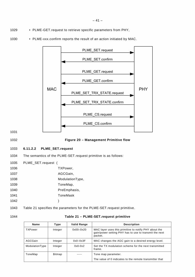
– 41 –
• PLME-GET.request to retrieve specific parameters from PHY, 1029
• PLME-xxx.confirm reports the result of an action initiated by MAC. 1030
MAC PHY
PLME_SET.request
PLME_SET.confirm
PLME_GET.request
PLME_GET.confirm
PLME_SET_TRX_STATE.request
PLME_SET_TRX_STATE.confirm
PLME_CS.request
PLME_CS.confirm
1031
Figure 20 – Management Primitive flow 1032
6.11.2.2 PLME_SET.request 1033
The semantics of the PLME-SET.request primitive is as follows: 1034
PLME_SET.request ( 1035
TXPower, 1036
AGCGain, 1037
ModulationType, 1038
ToneMap, 1039
PreEmphasis, 1040
ToneMask 1041
) 1042
Table 21 specifies the parameters for the PLME-SET.request primitive. 1043
Table 21 – PLME-SET.request primitive 1044
Name Type Valid Range Description
TXPower Integer 0x00–0x20 MAC layer uses this primitive to notify PHY about the gain/power setting PHY has to use to transmit the next packet.
AGCGain Integer 0x0–0x3F MAC changes the AGC gain to a desired energy level.
ModulationType Integer 0x0-0x2 Set the TX modulation scheme for the next transmitted frame.
ToneMap
Bitmap ----- Tone map parameter.
The value of 0 indicates to the remote transmitter that
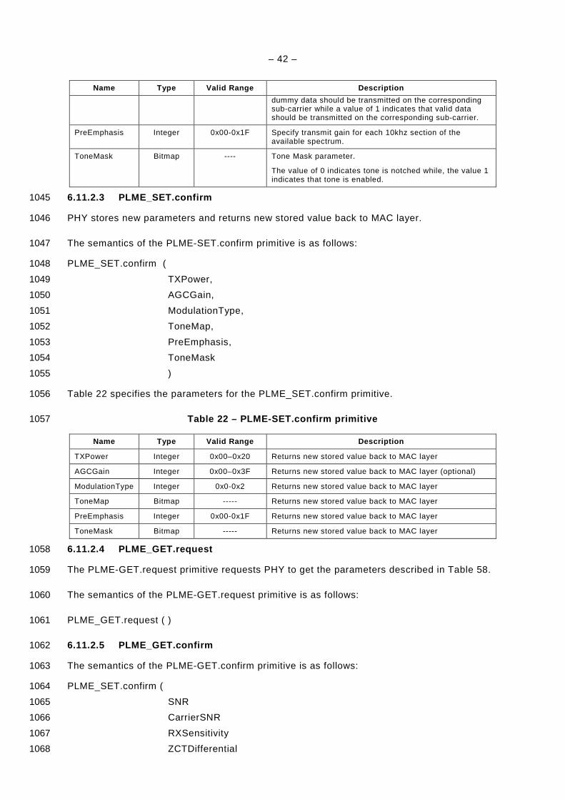
– 42 –
Name Type Valid Range Description
dummy data should be transmitted on the corresponding sub-carrier while a value of 1 indicates that valid data should be transmitted on the corresponding sub-carrier.
PreEmphasis Integer 0x00-0x1F Specify transmit gain for each 10khz section of the available spectrum.
ToneMask
Bitmap ---- Tone Mask parameter.
The value of 0 indicates tone is notched while, the value 1 indicates that tone is enabled.
6.11.2.3 PLME_SET.confirm 1045
PHY stores new parameters and returns new stored value back to MAC layer. 1046
The semantics of the PLME-SET.confirm primitive is as follows: 1047
PLME_SET.confirm ( 1048
TXPower, 1049
AGCGain, 1050
ModulationType, 1051
ToneMap, 1052
PreEmphasis, 1053
ToneMask 1054
) 1055
Table 22 specifies the parameters for the PLME_SET.confirm primitive. 1056
Table 22 – PLME-SET.confirm primitive 1057
Name Type Valid Range Description
TXPower Integer 0x00–0x20 Returns new stored value back to MAC layer
AGCGain Integer 0x00–0x3F Returns new stored value back to MAC layer (optional)
ModulationType Integer 0x0-0x2 Returns new stored value back to MAC layer
ToneMap Bitmap ----- Returns new stored value back to MAC layer
PreEmphasis Integer 0x00-0x1F Returns new stored value back to MAC layer
ToneMask Bitmap ----- Returns new stored value back to MAC layer
6.11.2.4 PLME_GET.request 1058
The PLME-GET.request primitive requests PHY to get the parameters described in Table 58. 1059
The semantics of the PLME-GET.request primitive is as follows: 1060
PLME_GET.request ( ) 1061
6.11.2.5 PLME_GET.confirm 1062
The semantics of the PLME-GET.confirm primitive is as follows: 1063
PLME_SET.confirm ( 1064
SNR 1065
CarrierSNR 1066
RXSensitivity 1067
ZCTDifferential 1068
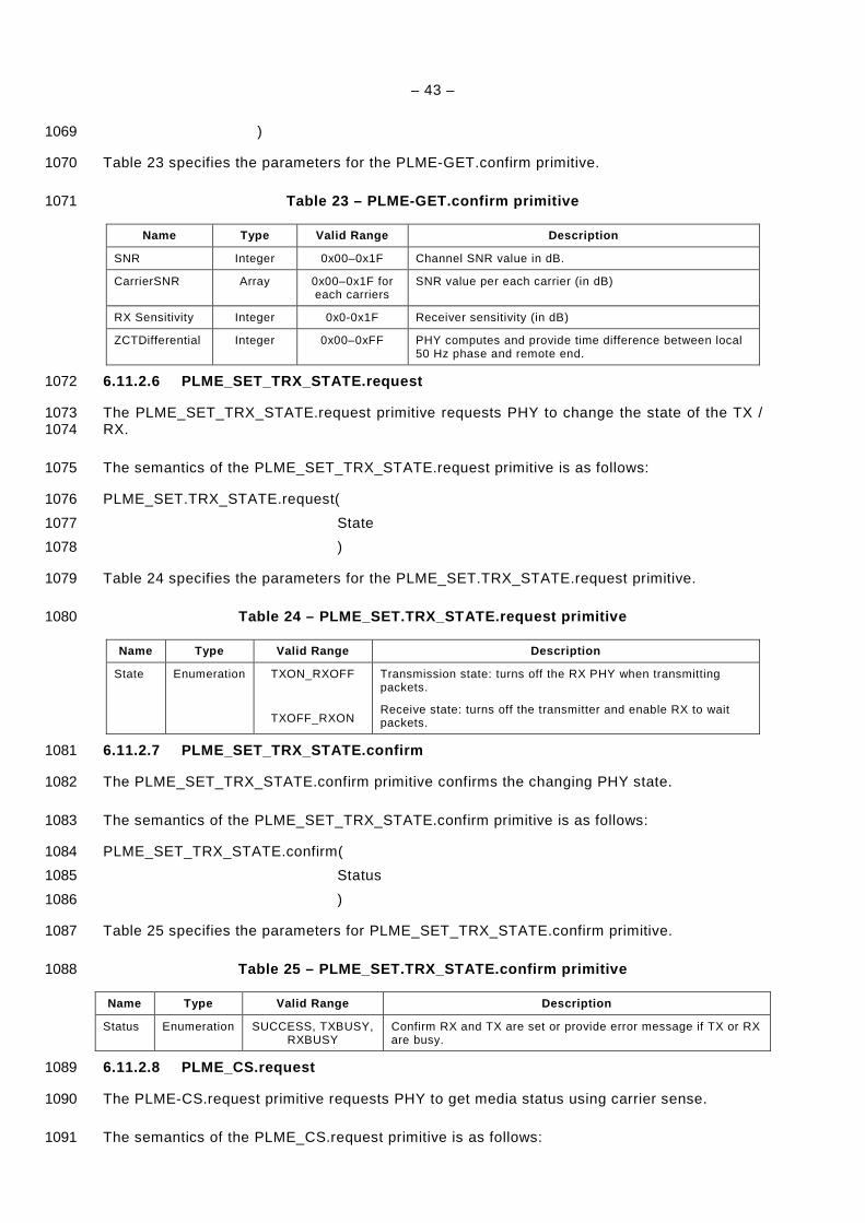
– 43 –
) 1069
Table 23 specifies the parameters for the PLME-GET.confirm primitive. 1070
Table 23 – PLME-GET.confirm primitive 1071
Name Type Valid Range Description
SNR Integer 0x00–0x1F Channel SNR value in dB.
CarrierSNR Array 0x00–0x1F for each carriers
SNR value per each carrier (in dB)
RX Sensitivity Integer 0x0-0x1F Receiver sensitivity (in dB)
ZCTDifferential Integer 0x00–0xFF PHY computes and provide time difference between local 50 Hz phase and remote end.
6.11.2.6 PLME_SET_TRX_STATE.request 1072
The PLME_SET_TRX_STATE.request primitive requests PHY to change the state of the TX / 1073 RX. 1074
The semantics of the PLME_SET_TRX_STATE.request primitive is as follows: 1075
PLME_SET.TRX_STATE.request( 1076
State 1077
) 1078
Table 24 specifies the parameters for the PLME_SET.TRX_STATE.request primitive. 1079
Table 24 – PLME_SET.TRX_STATE.request primitive 1080
Name Type Valid Range Description
State Enumeration TXON_RXOFF
TXOFF_RXON
Transmission state: turns off the RX PHY when transmitting packets.
Receive state: turns off the transmitter and enable RX to wait packets.
6.11.2.7 PLME_SET_TRX_STATE.confirm 1081
The PLME_SET_TRX_STATE.confirm primitive confirms the changing PHY state. 1082
The semantics of the PLME_SET_TRX_STATE.confirm primitive is as follows: 1083
PLME_SET_TRX_STATE.confirm( 1084
Status 1085
) 1086
Table 25 specifies the parameters for PLME_SET_TRX_STATE.confirm primitive. 1087
Table 25 – PLME_SET.TRX_STATE.confirm primitive 1088
Name Type Valid Range Description
Status Enumeration SUCCESS, TXBUSY, RXBUSY
Confirm RX and TX are set or provide error message if TX or RX are busy.
6.11.2.8 PLME_CS.request 1089
The PLME-CS.request primitive requests PHY to get media status using carrier sense. 1090
The semantics of the PLME_CS.request primitive is as follows: 1091
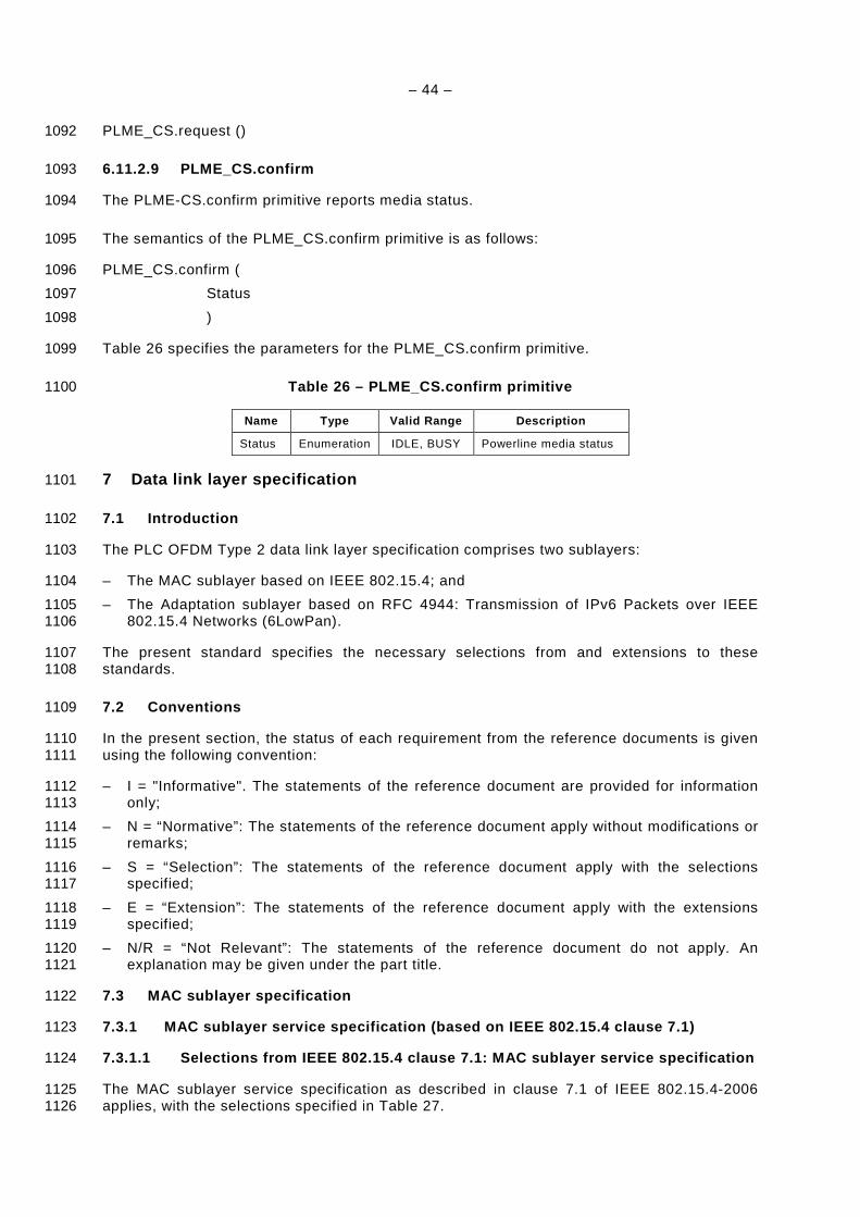
– 44 –
PLME_CS.request () 1092
6.11.2.9 PLME_CS.confirm 1093
The PLME-CS.confirm primitive reports media status. 1094
The semantics of the PLME_CS.confirm primitive is as follows: 1095
PLME_CS.confirm ( 1096
Status 1097
) 1098
Table 26 specifies the parameters for the PLME_CS.confirm primitive. 1099
Table 26 – PLME_CS.confirm primitive 1100
Name Type Valid Range Description
Status Enumeration IDLE, BUSY Powerline media status
7 Data link layer specification 1101
7.1 Introduction 1102
The PLC OFDM Type 2 data link layer specification comprises two sublayers: 1103
– The MAC sublayer based on IEEE 802.15.4; and 1104
– The Adaptation sublayer based on RFC 4944: Transmission of IPv6 Packets over IEEE 1105 802.15.4 Networks (6LowPan). 1106
The present standard specifies the necessary selections from and extensions to these 1107 standards. 1108
7.2 Conventions 1109
In the present section, the status of each requirement from the reference documents is given 1110 using the following convention: 1111
– I = "Informative". The statements of the reference document are provided for information 1112 only; 1113
– N = “Normative”: The statements of the reference document apply without modifications or 1114 remarks; 1115
– S = “Selection”: The statements of the reference document apply with the selections 1116 specified; 1117
– E = “Extension”: The statements of the reference document apply with the extensions 1118 specified; 1119
– N/R = “Not Relevant”: The statements of the reference document do not apply. An 1120 explanation may be given under the part title. 1121
7.3 MAC sublayer specification 1122
7.3.1 MAC sublayer service specification (based on IEEE 802.15.4 clause 7.1) 1123
7.3.1.1 Selections from IEEE 802.15.4 clause 7.1: M AC sublayer service specification 1124
The MAC sublayer service specification as described in clause 7.1 of IEEE 802.15.4-2006 1125 applies, with the selections specified in Table 27. 1126
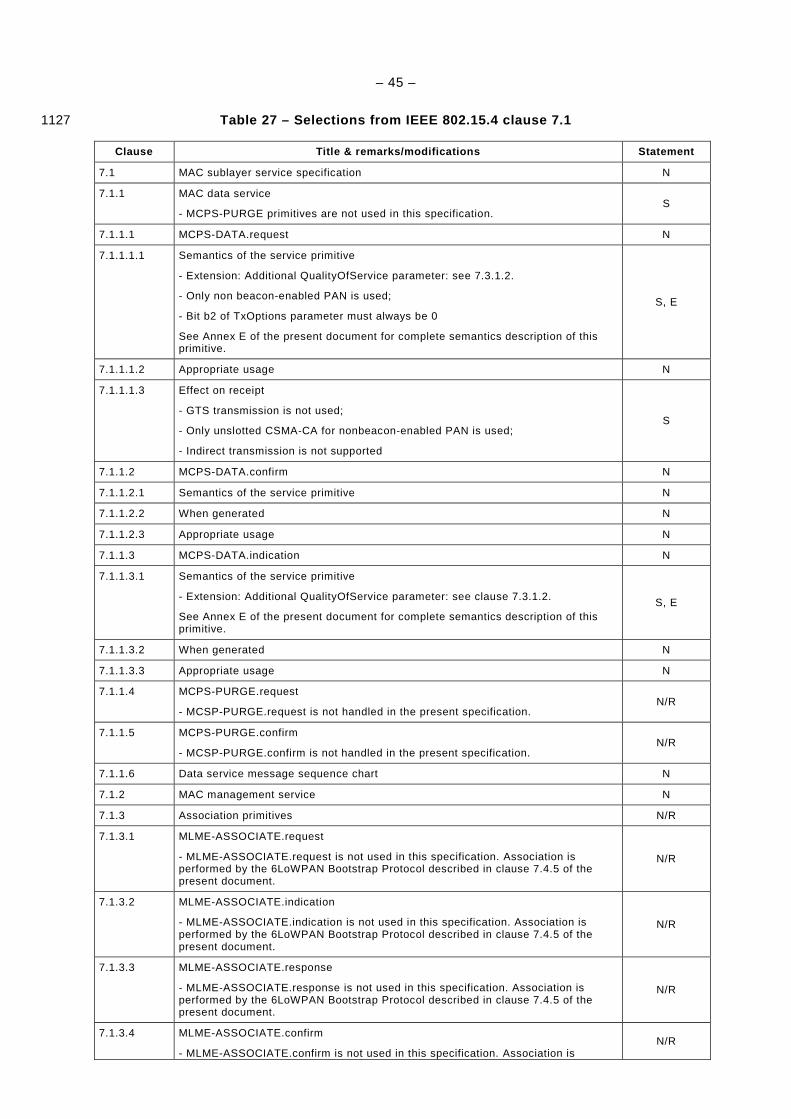
– 45 –
Table 27 – Selections from IEEE 802.15.4 clause 7.1 1127
Clause Title & remarks/modifications Statement
7.1 MAC sublayer service specification N
7.1.1 MAC data service
- MCPS-PURGE primitives are not used in this specification. S
7.1.1.1 MCPS-DATA.request N
7.1.1.1.1 Semantics of the service primitive
- Extension: Additional QualityOfService parameter: see 7.3.1.2.
- Only non beacon-enabled PAN is used;
- Bit b2 of TxOptions parameter must always be 0
See Annex E of the present document for complete semantics description of this primitive.
S, E
7.1.1.1.2 Appropriate usage N
7.1.1.1.3 Effect on receipt
- GTS transmission is not used;
- Only unslotted CSMA-CA for nonbeacon-enabled PAN is used;
- Indirect transmission is not supported
S
7.1.1.2 MCPS-DATA.confirm N
7.1.1.2.1 Semantics of the service primitive N
7.1.1.2.2 When generated N
7.1.1.2.3 Appropriate usage N
7.1.1.3 MCPS-DATA.indication N
7.1.1.3.1 Semantics of the service primitive
- Extension: Additional QualityOfService parameter: see clause 7.3.1.2.
See Annex E of the present document for complete semantics description of this primitive.
S, E
7.1.1.3.2 When generated N
7.1.1.3.3 Appropriate usage N
7.1.1.4 MCPS-PURGE.request
- MCSP-PURGE.request is not handled in the present specification. N/R
7.1.1.5 MCPS-PURGE.confirm
- MCSP-PURGE.confirm is not handled in the present specification. N/R
7.1.1.6 Data service message sequence chart N
7.1.2 MAC management service N
7.1.3 Association primitives N/R
7.1.3.1 MLME-ASSOCIATE.request
- MLME-ASSOCIATE.request is not used in this specification. Association is performed by the 6LoWPAN Bootstrap Protocol described in clause 7.4.5 of the present document.
N/R
7.1.3.2 MLME-ASSOCIATE.indication
- MLME-ASSOCIATE.indication is not used in this specification. Association is performed by the 6LoWPAN Bootstrap Protocol described in clause 7.4.5 of the present document.
N/R
7.1.3.3 MLME-ASSOCIATE.response
- MLME-ASSOCIATE.response is not used in this specification. Association is performed by the 6LoWPAN Bootstrap Protocol described in clause 7.4.5 of the present document.
N/R
7.1.3.4 MLME-ASSOCIATE.confirm
- MLME-ASSOCIATE.confirm is not used in this specification. Association is N/R

– 46 –
Clause Title & remarks/modifications Statement
performed by the 6LoWPAN Bootstrap Protocol described in clause 7.4.5 of the present document.
7.1.3.5 Association message sequence chart
- The association message sequence chart described in figure 31 must be ignored for this specification, as association is performed using the bootstrap mechanism described in clause 7.4.5 of the present document.
N/R
7.1.4 Disassociation primitive N/R
7.1.4.1 MLME-DISASSOCIATE.request
- MLME-DISASSOCIATE.request is not used in this specification. Disassociation is performed by the 6LoWPAN Bootstrap Protocol described in clause 7.4.5 of the present document.
N/R
7.1.4.2 MLME-DISASSOCIATE.indication
- MLME-DISASSOCIATE.indication is not used in this specification. Disassociation is performed by the 6LoWPAN Bootstrap Protocol described in clause 7.4.5 of the present document.
N/R
7.1.4.3 MLME-DISASSOCIATE.confirm
- MLME-DISASSOCIATE.confirm is not used in this specification. Disassociation is performed by the 6LoWPAN Bootstrap Protocol described in clause 7.4.5 of the present document.
N/R
7.1.4.4 Disassociation message sequence chart
- The disassociation message sequence chart described in figure 31 must be ignored for this specification, as disassociation is performed using the bootstrap mechanism described in clause 7.4.5 of the present document.
N/R
7.1.5 Beacon notification primitive N/R
7.1.5.1 MLME-BEACON-NOTIFY.indication
- Only nonbeacon-enabled PANs are used.
- This primitive is generated upon reception of a beacon during an active scan
S
7.1.6 Primitives for reading PIB attributes N
7.1.6.1 MLME-GET.request N
7.1.6.1.1 Semantics of the service primitive N
7.1.6.1.2 Appropriate usage N
7.1.6.1.3 Effect on receipt N
7.1.6.2 MLME-GET.confirm N
7.1.6.2.1 Semantics of the service primitive N
7.1.6.2.2 When generated N
7.1.6.2.3 Appropriate usage N
7.1.7 GTS management primitives
- GTS are not used in the present specification N/R
7.1.8 Primitives for orphan notification
- Beacon synchronization is not used in the present specification N/R
7.1.9 Primitives for resetting the MAC sublayer N
7.1.9.1 MLME-RESET.request N
7.1.9.1.1 Semantics of the service primitive N
7.1.9.1.2 Appropriate usage N
7.1.9.1.3 Effect on receipt N
7.1.9.2 MLME-RESET.confirm N
7.1.9.2.1 Semantics of the service primitive N
7.1.9.2.2 When generated N
7.1.9.2.3 Appropriate usage N

– 47 –
Clause Title & remarks/modifications Statement
7.1.10 Primitives for specifying the receiver enable time
- The primitives for specifying the receiver enable time are not used in the present application of the norm. The receiver is always enabled
N/R
7.1.11 Primitives for channel scanning N
7.1.11.1 MLME-SCAN.request N
7.1.11.1.1 Semantics of the service primitive
- The only supported values for the ScanType parameter is 0x01 for active scan.
- The ScanChannels parameter is not used, and all of its 27 bits must be set to 0.
- The ChannelPage parameter is not used and must always be set to 0.
- The SecurityLevel must be 0. Thus the KeyIdMode, KeyIndex and KeySource parameters can be ignored and set to 0.
S
7.1.11.1.2 Appropriate usage
- Only active scan is supported
- ED scans, passive scans and orphan scans are not used. All devices must be capable of performing active scans.
S
7.1.11.1.3 Effect on receipt
- Only active scan is supported,
- ED scan, passive scan and orphan scan are not supported,
- There is no physical channel notion during the scans, as the underlying PHY layer does not support multiple channels.
S
7.1.11.2 MLME-SCAN.confirm N
7.1.11.2.1 Semantics of the service primitive
- The only supported values for the ScanType parameter is 0x01 for active scan.
- The UnscannedChannels parameter is not used, and all of its 27 bits must be set to 0.
- The ChannelPage parameter is not used and must always be set to 0.
- The EnergyDetectList parameter is not used, and must always be null.
S
7.1.11.2.2 When generated
- Only active scan is supported
- ED scan, passive scan and orphan scan are not supported.
S
7.1.11.2.3 Appropriate usage N
7.1.11.3 Channel scan message sequence chart
- Figure 79 must be ignored (ED scan not supported)
- Figure 82 must be ignored (passive scan not supported)
- Figure 86 must be ignored (orphan scan not supported)
- Active scan message sequence chart is specified in clause 7.4.5.2.2 of the present document, and replaces figure 83 of the reference document.
S
7.1.12 Communication status primitive N
7.1.12.1 MLME-COMM-STATUS.indication N
7.1.12.1.1 Semantics of the service primitive
- Valid values for the status parameters are:
SUCCESS, CHANNEL_ACCESS_FAILURE, NO_ACK, COUNTER_ERROR, FRAME_TOO_LONG, IMPROPER_KEY_TYPE, IMPROPER_SECURITY_LEVEL, SECURITY_ERROR, UNAVAILABLE_KEY, UNSUPPORTED_LEGACY, UNSUPPORTED_SECURITY or INVALID_PARAMETER
S
7.1.12.1.2 When generated
- This primitive is not used to notify the upper layer about association, disassociation, indirect transmission and transactions management
S
7.1.12.1.3 Appropriate usage N
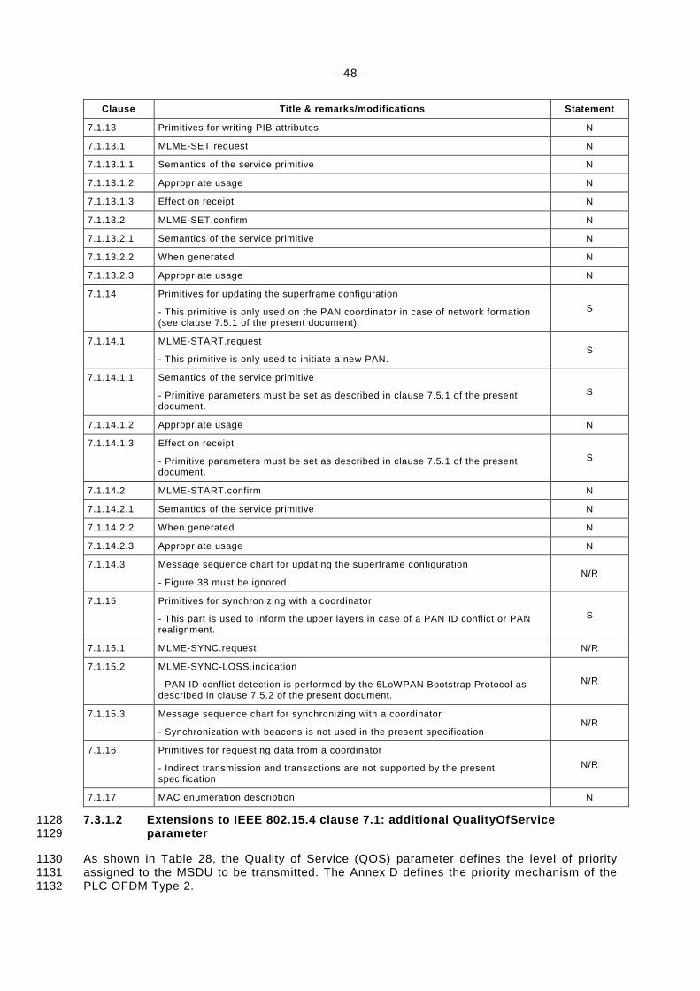
– 48 –
Clause Title & remarks/modifications Statement
7.1.13 Primitives for writing PIB attributes N
7.1.13.1 MLME-SET.request N
7.1.13.1.1 Semantics of the service primitive N
7.1.13.1.2 Appropriate usage N
7.1.13.1.3 Effect on receipt N
7.1.13.2 MLME-SET.confirm N
7.1.13.2.1 Semantics of the service primitive N
7.1.13.2.2 When generated N
7.1.13.2.3 Appropriate usage N
7.1.14 Primitives for updating the superframe configuration
- This primitive is only used on the PAN coordinator in case of network formation (see clause 7.5.1 of the present document).
S
7.1.14.1 MLME-START.request
- This primitive is only used to initiate a new PAN. S
7.1.14.1.1 Semantics of the service primitive
- Primitive parameters must be set as described in clause 7.5.1 of the present document.
S
7.1.14.1.2 Appropriate usage N
7.1.14.1.3 Effect on receipt
- Primitive parameters must be set as described in clause 7.5.1 of the present document.
S
7.1.14.2 MLME-START.confirm N
7.1.14.2.1 Semantics of the service primitive N
7.1.14.2.2 When generated N
7.1.14.2.3 Appropriate usage N
7.1.14.3 Message sequence chart for updating the superframe configuration
- Figure 38 must be ignored. N/R
7.1.15 Primitives for synchronizing with a coordinator
- This part is used to inform the upper layers in case of a PAN ID conflict or PAN realignment.
S
7.1.15.1 MLME-SYNC.request N/R
7.1.15.2 MLME-SYNC-LOSS.indication
- PAN ID conflict detection is performed by the 6LoWPAN Bootstrap Protocol as described in clause 7.5.2 of the present document.
N/R
7.1.15.3 Message sequence chart for synchronizing with a coordinator
- Synchronization with beacons is not used in the present specification N/R
7.1.16 Primitives for requesting data from a coordinator
- Indirect transmission and transactions are not supported by the present specification
N/R
7.1.17 MAC enumeration description N
7.3.1.2 Extensions to IEEE 802.15.4 clause 7.1: add itional QualityOfService 1128 parameter 1129
As shown in Table 28, the Quality of Service (QOS) parameter defines the level of priority 1130 assigned to the MSDU to be transmitted. The Annex D defines the priority mechanism of the 1131 PLC OFDM Type 2. 1132

– 49 –
Table 28 – QualityOfService parameter definition 1133
Name Type Valid range Description
QualityOfService Integer 0x00 – 0x02 The QOS (Quality of Service) parameter of the MSDU to be transmitted by the MAC sublayer entity. This value can take one of the following values:
0 = Normal priority,
1 = High priority,
2 = Contention free
7.3.2 MAC frame formats (based on IEEE 802.15.4 cla use 7.2) 1134
7.3.2.1 Selections from IEEE 802.15.4 clause 7.2: M AC frame formats 1135
The MAC frame formats as described in clause 7.2 of IEEE 802.15.4-2006 apply, with the 1136 selections specified in Table 29. 1137
Table 29 – Selections from clause 7.2 of the IEEE 8 02.15.4 1138
Clause Title & remarks/modifications Statement
7.2 MAC frame formats N
7.2.1 General MAC frame format
- Segment Control fields are added to MHR (see 7.3.2.2)
- Detailed description of the Segment Control fields is shown in Table 31.
E
7.2.1.1 Frame control field N
7.2.1.1.1 Frame type subfield
- The present specification does not use acknowledgement frame type value.
- The detailed ACK implementation is described in clause 5 and annex Annex F of the present document. An acknowledgment can be sent by invoking the PD-ACK.request primitive (see 6.11.1.1).
S
7.2.1.1.2 Security Enabled subfield N
7.2.1.1.3 Frame Pending subfield
- Indirect transmission is not supported, so this bit must always be set to 0. S
7.2.1.1.4 Acknowledgement Request subfield
- The present specification translates the Acknowledgment Request subfield to the proper delimiter type of frame control header.
- The detailed ACK implementation is described in clause 5 and annex Annex F of the present document. An acknowledgement can be sent by invoking the PD-ACK.request primitive (see 6.11.1.1).
S
7.2.1.1.5 PAN ID compression subfield N
7.2.1.1.6 Destination Addressing Mode subfield N
7.2.1.1.7 Frame Version subfield
- These 2 bits are reserved for future use. In this version of the specification they must be set to 0.
S
7.2.1.1.8 Source Addressing Mode subfield N
7.2.1.2 Sequence Number field N
7.2.1.3 Destination PAN Identifier field N
7.2.1.4 Destination Address field N
7.2.1.5 Source PAN Identifier field N
7.2.1.6 Source Address field N
7.2.1.7 Auxiliary Security Header field
- Possible lengths for the Auxiliary Security Header are 0 and 5 bytes (see clause 8)
S
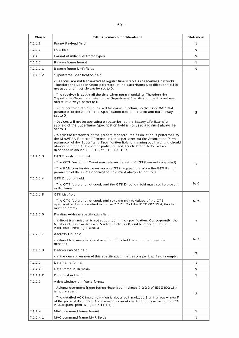
– 50 –
Clause Title & remarks/modifications Statement
7.2.1.8 Frame Payload field N
7.2.1.9 FCS field N
7.2.2 Format of individual frame types N
7.2.2.1 Beacon frame format N
7.2.2.1.1 Beacon frame MHR fields N
7.2.2.1.2 Superframe Specification field
- Beacons are not transmitted at regular time intervals (beaconless network). Therefore the Beacon Order parameter of the Superframe Specification field is not used and must always be set to 0.
- The receiver is active all the time when not transmitting. Therefore the Superframe Order parameter of the Superframe Specification field is not used and must always be set to 0.
- No superframe structure is used for communication, so the Final CAP Slot parameter of the Superframe Specification field is not used and must always be set to 0.
- Devices will not be operating on batteries, so the Battery Life Extension subfield of the Superframe Specification field is not used and must always be set to 0.
- Within the framework of the present standard, the association is performed by the 6LoWPAN Bootstrap Protocol in the upper layer, so the Association Permit parameter of the Superframe Specification field is meaningless here, and should always be set to 1. If another profile is used, this field should be set as described in clause 7.2.2.1.2 of IEEE 802.15.4.
S
7.2.2.1.3 GTS Specification field
- The GTS Descriptor Count must always be set to 0 (GTS are not supported).
- The PAN coordinator never accepts GTS request, therefore the GTS Permit parameter of the GTS Specification field must always be set to 0.
S
7.2.2.1.4 GTS Direction field
- The GTS feature is not used, and the GTS Direction field must not be present in the frame
N/R
7.2.2.1.5 GTS List field
- The GTS feature is not used, and considering the values of the GTS specification field described in clause 7.2.2.1.3 of the IEEE 802.15.4, this list must be empty
N/R
7.2.2.1.6 Pending Address specification field
- Indirect transmission is not supported in this specification. Consequently, the Number of Short Addresses Pending is always 0, and Number of Extended Addresses Pending is also 0.
S
7.2.2.1.7 Address List field
- Indirect transmission is not used, and this field must not be present in beacons.
N/R
7.2.2.1.8 Beacon Payload field
- In the current version of this specification, the beacon payload field is empty. S
7.2.2.2 Data frame format N
7.2.2.2.1 Data frame MHR fields N
7.2.2.2.2 Data payload field N
7.2.2.3 Acknowledgement frame format
- Acknowledgement frame format described in clause 7.2.2.3 of IEEE 802.15.4 is not relevant.
- The detailed ACK implementation is described in clause 5 and annex Annex F of the present document. An acknowledgement can be sent by invoking the PD-ACK.request primitive (see 6.11.1.1).
S
7.2.2.4 MAC command frame format N
7.2.2.4.1 MAC command frame MHR fields N
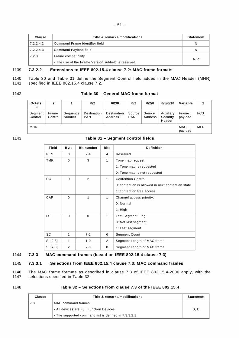
– 51 –
Clause Title & remarks/modifications Statement
7.2.2.4.2 Command Frame Identifier field N
7.2.2.4.3 Command Payload field N
7.2.3 Frame compatibility
- The use of the Frame Version subfield is reserved. N/R
7.3.2.2 Extensions to IEEE 802.15.4 clause 7.2: MAC frame formats 1139
Table 30 and Table 31 define the Segment Control field added in the MAC Header (MHR) 1140 specified in IEEE 802.15.4 clause 7.2. 1141
Table 30 – General MAC frame format 1142
Octets: 3
2 1 0/2 0/2/8 0/2 0/2/8 0/5/6/10 Variable 2
Segment Control
Frame Control
Sequence Number
Destination PAN
Destination Address
Source PAN
Source Address
Auxiliary Security Header
Frame payload
FCS
MHR MAC payload
MFR
Table 31 – Segment control fields 1143
Field Byte Bit number Bits Definition
RES 0 7-4 4 Reserved
TMR 0 3 1 Tone map request
1: Tone map is requested
0: Tone map is not requested
CC 0 2 1 Contention Control:
0: contention is allowed in next contention state
1: contention free access
CAP 0 1 1 Channel access priority:
0: Normal
1: High
LSF 0 0 1 Last Segment Flag
0: Not last segment
1: Last segment
SC 1 7-2 6 Segment Count
SL[9-8] 1 1-0 2 Segment Length of MAC frame
SL[7-0] 2 7-0 8 Segment Length of MAC frame
7.3.3 MAC command frames (based on IEEE 802.15.4 cl ause 7.3) 1144
7.3.3.1 Selections from IEEE 802.15.4 clause 7.3: M AC command frames 1145
The MAC frame formats as described in clause 7.3 of IEEE 802.15.4-2006 apply, with the 1146 selections specified in Table 32. 1147
Table 32 – Selections from clause 7.3 of the IEEE 8 02.15.4 1148
Clause Title & remarks/modifications Statement
7.3 MAC command frames
- All devices are Full Function Devices
- The supported command list is defined in 7.3.3.2.1
S, E
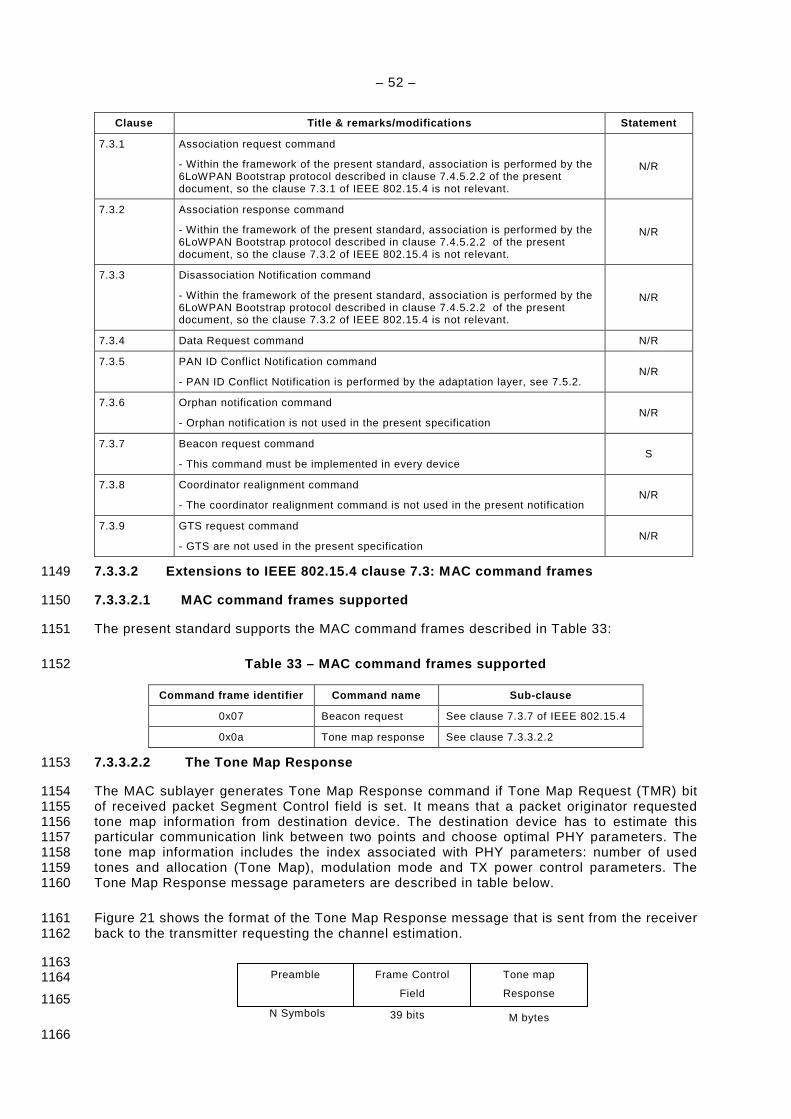
– 52 –
Clause Title & remarks/modifications Statement
7.3.1 Association request command
- Within the framework of the present standard, association is performed by the 6LoWPAN Bootstrap protocol described in clause 7.4.5.2.2 of the present document, so the clause 7.3.1 of IEEE 802.15.4 is not relevant.
N/R
7.3.2 Association response command
- Within the framework of the present standard, association is performed by the 6LoWPAN Bootstrap protocol described in clause 7.4.5.2.2 of the present document, so the clause 7.3.2 of IEEE 802.15.4 is not relevant.
N/R
7.3.3 Disassociation Notification command
- Within the framework of the present standard, association is performed by the 6LoWPAN Bootstrap protocol described in clause 7.4.5.2.2 of the present document, so the clause 7.3.2 of IEEE 802.15.4 is not relevant.
N/R
7.3.4 Data Request command N/R
7.3.5 PAN ID Conflict Notification command
- PAN ID Conflict Notification is performed by the adaptation layer, see 7.5.2. N/R
7.3.6 Orphan notification command
- Orphan notification is not used in the present specification N/R
7.3.7 Beacon request command
- This command must be implemented in every device S
7.3.8 Coordinator realignment command
- The coordinator realignment command is not used in the present notification N/R
7.3.9 GTS request command
- GTS are not used in the present specification N/R
7.3.3.2 Extensions to IEEE 802.15.4 clause 7.3: MAC command frames 1149
7.3.3.2.1 MAC command frames supported 1150
The present standard supports the MAC command frames described in Table 33: 1151
Table 33 – MAC command frames supported 1152
Command frame identifier Command name Sub-clause
0x07 Beacon request See clause 7.3.7 of IEEE 802.15.4
0x0a Tone map response See clause 7.3.3.2.2
7.3.3.2.2 The Tone Map Response 1153
The MAC sublayer generates Tone Map Response command if Tone Map Request (TMR) bit 1154 of received packet Segment Control field is set. It means that a packet originator requested 1155 tone map information from destination device. The destination device has to estimate this 1156 particular communication link between two points and choose optimal PHY parameters. The 1157 tone map information includes the index associated with PHY parameters: number of used 1158 tones and allocation (Tone Map), modulation mode and TX power control parameters. The 1159 Tone Map Response message parameters are described in table below. 1160
Figure 21 shows the format of the Tone Map Response message that is sent from the receiver 1161 back to the transmitter requesting the channel estimation. 1162
1163 1164
1165
1166 M bytes 39 bits N Symbols
Preamble Frame Control
Field
Tone map
Response
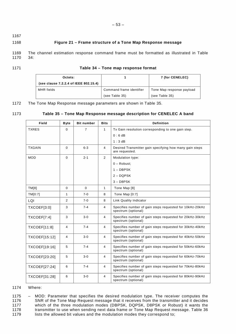
– 53 –
1167
Figure 21 – Frame structure of a Tone Map Response message 1168
The channel estimation response command frame must be formatted as illustrated in Table 1169 34: 1170
Table 34 – Tone map response format 1171
Octets:
(see clause 7.2.2.4 of IEEE 802.15.4)
1 7 (for CENELEC)
MHR fields Command frame identifier
(see Table 35)
Tone Map response payload
(see Table 35)
The Tone Map Response message parameters are shown in Table 35. 1172
Table 35 – Tone Map Response message description fo r CENELEC A band 1173
Field Byte Bit number Bits Definition
TXRES 0 7 1 Tx Gain resolution corresponding to one gain step.
0 : 6 dB
1 : 3 dB
TXGAIN 0 6-3 4 Desired Transmitter gain specifying how many gain steps are requested.
MOD 0 2-1 2 Modulation type:
0 – Robust;
1 – DBPSK
2 – DQPSK
3 – D8PSK
TM[8] 0 0 1 Tone Map [8]
TM[0:7] 1 7-0 8 Tone Map [0:7]
LQI 2 7-0 8 Link Quality Indicator
TXCOEF[3:0] 3 7-4 4 Specifies number of gain steps requested for 10kHz-20kHz spectrum (optional)
TXCOEF[7:4] 3 3-0 4 Specifies number of gain steps requested for 20kHz-30kHz spectrum (optional)
TXCOEF[11:8] 4 7-4 4 Specifies number of gain steps requested for 30kHz-40kHz spectrum (optional)
TXCOEF[15:12] 4 3-0 4 Specifies number of gain steps requested for 40kHz-50kHz spectrum (optional)
TXCOEF[19:16] 5 7-4 4 Specifies number of gain steps requested for 50kHz-60kHz spectrum (optional)
TXCOEF[23:20] 5 3-0 4 Specifies number of gain steps requested for 60kHz-70kHz spectrum (optional)
TXCOEF[27:24] 6 7-4 4 Specifies number of gain steps requested for 70kHz-80kHz spectrum (optional)
TXCOEF[31:28] 6 3-0 4 Specifies number of gain steps requested for 80kHz-90kHz spectrum (optional)
Where: 1174
– MOD: Parameter that specifies the desired modulation type. The receiver computes the 1175 SNR of the Tone Map Request message that it receives from the transmitter and it decides 1176 which of the three modulation modes (DBPSK, DQPSK, D8PSK or Robust) it wants the 1177 transmitter to use when sending next data frame or Tone Map Request message. Table 36 1178 lists the allowed bit values and the modulation modes they correspond to; 1179

– 54 –
Table 36 – Modulation Method Field 1180
MOD Value Interpretation
00 Robust Modulation
01 DBPSK Modulation
10 DQPSK Modulation
11 D8PSK Modulation
– TXRES: Parameter that specifies the transmit gain resolution corresponding to one gain 1181 step; 1182
– TXGAIN: Parameter that specifies to the transmitter the total amount of gain that it should 1183 apply to its transmitted signal. The value in this parameter shall specify the total number 1184 of gain steps needed. The receiver computes the received signal level and compares it to 1185 a VTARGET (pre-defined desired receive level). The difference in dB between the two 1186 values is mapped to a 5-bit value that specifies the amount of gain increase or decrease 1187 that the transmitter shall apply to the next frame to be transmitted. A “0” in the most 1188 significant bit indicates a positive gain value, hence an increase in the transmitter gain 1189 and a 1 indicates a negative gain value, hence a decrease in the transmitter gains. A 1190 value of TXGAIN = 0 informs the transmitter to use the same gain value it used for 1191 previous frame (Default value); 1192
– TM: Parameter that specifies the Tone Map. The receiver estimates the per-tone quality of 1193 the channel and maps each sub-band (6 tones per sub-band) to a one-bit value where a 1194 value of 0 indicates to the remote transmitter that dummy data should be transmitted on 1195 the corresponding sub-carrier while a value of “1” indicates that valid data should be 1196 transmitted on the corresponding sub-carrier; 1197
– TXCOEF (optional): Parameter that specifies transmitter gain for each 10 kHz section of 1198 the available spectrum. The receiver measures the frequency-dependent attenuation of 1199 the channel and may request the transmitter to compensate for this attenuation by 1200 increasing the transmit power on sections of the spectrum that are experiencing 1201 attenuation in order to equalize the received signal. Each 10 kHz section is mapped to a 1202 4-bit value where a “0” in the most significant bit indicates a positive gain value, hence an 1203 increase in the transmitter gain is requested for that section, and a “1” indicates a 1204 negative gain value, hence a decrease in the transmitter gain is requested for that section. 1205 Implementing this feature is optional and it is intended for frequency selective channels. If 1206 this feature is not implemented, the value zero should be used. 1207
On reception of a Tone Map Response command frame, the MAC sublayer updates the 1208 neighbour table with the corresponding Tone Map and communication parameters for that 1209 device. If no entry already exists in the table for that device a new entry should be added, 1210 based on implementation dependant limitations. The neighbour table is defined in Table 42. 1211
The following procedure must be used to perform the adaptive tone mapping function: 1212
a) When a station is ready to transmit data it will first check if the neighbour table already 1213 has a record related to the destination device address. If the record don’t exists or aged 1214 (Age counter is 0), the MAC sublayer sets the TMR bit of outgoing packet Segment 1215 Control field and requests new Tone Map information. In this case the MAC data should 1216 be sent in Robust mode; 1217
b) If a neighbour table record exists and it is not aged the MAC sublayer does not need to 1218 send Tone Map Request message. In this case, the MAC sublayer uses information from 1219 the neighbour table to properly configure physical TX in transmitting mode and construct 1220 Frame Control Header (FCH) of the outgoing frame; 1221
c) When the destination station receives a data frame it shall check the Tone Map Request 1222 bit in the Segment Control field. If the bit is set, the destination station must measure the 1223 per-carrier quality of the channel, construct and send a Tone Map Response message 1224 back to the originator station. The destination station must not send a Tone Map 1225 Response message if the Tone Map Request bit is not set. The Tone Map Response 1226 message shall always be transmitted using default Robust modulation. The destination 1227 device uses parameters from the Frame Control Header to decode the MAC data fields; 1228
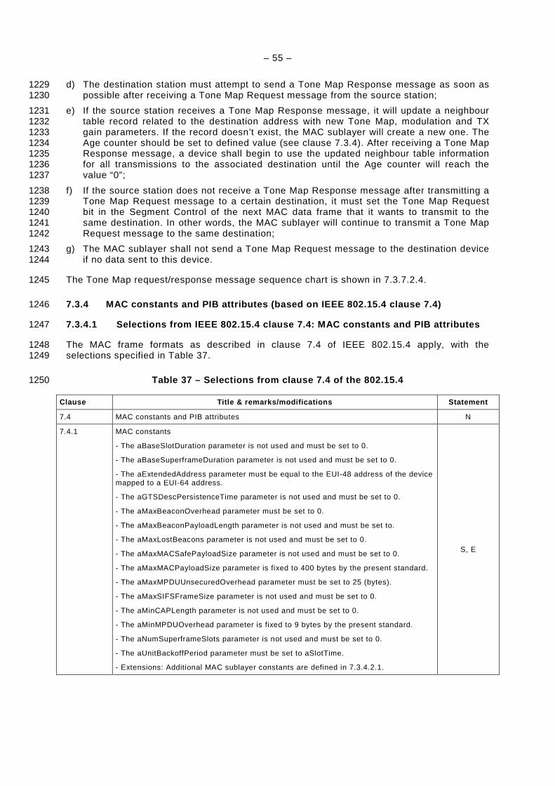
– 55 –
d) The destination station must attempt to send a Tone Map Response message as soon as 1229 possible after receiving a Tone Map Request message from the source station; 1230
e) If the source station receives a Tone Map Response message, it will update a neighbour 1231 table record related to the destination address with new Tone Map, modulation and TX 1232 gain parameters. If the record doesn’t exist, the MAC sublayer will create a new one. The 1233 Age counter should be set to defined value (see clause 7.3.4). After receiving a Tone Map 1234 Response message, a device shall begin to use the updated neighbour table information 1235 for all transmissions to the associated destination until the Age counter will reach the 1236 value “0”; 1237
f) If the source station does not receive a Tone Map Response message after transmitting a 1238 Tone Map Request message to a certain destination, it must set the Tone Map Request 1239 bit in the Segment Control of the next MAC data frame that it wants to transmit to the 1240 same destination. In other words, the MAC sublayer will continue to transmit a Tone Map 1241 Request message to the same destination; 1242
g) The MAC sublayer shall not send a Tone Map Request message to the destination device 1243 if no data sent to this device. 1244
The Tone Map request/response message sequence chart is shown in 7.3.7.2.4. 1245
7.3.4 MAC constants and PIB attributes (based on IE EE 802.15.4 clause 7.4) 1246
7.3.4.1 Selections from IEEE 802.15.4 clause 7.4: M AC constants and PIB attributes 1247
The MAC frame formats as described in clause 7.4 of IEEE 802.15.4 apply, with the 1248 selections specified in Table 37. 1249
Table 37 – Selections from clause 7.4 of the 802.15 .4 1250
Clause Title & remarks/modifications Statement
7.4 MAC constants and PIB attributes N
7.4.1 MAC constants
- The aBaseSlotDuration parameter is not used and must be set to 0.
- The aBaseSuperframeDuration parameter is not used and must be set to 0.
- The aExtendedAddress parameter must be equal to the EUI-48 address of the device mapped to a EUI-64 address.
- The aGTSDescPersistenceTime parameter is not used and must be set to 0.
- The aMaxBeaconOverhead parameter must be set to 0.
- The aMaxBeaconPayloadLength parameter is not used and must be set to.
- The aMaxLostBeacons parameter is not used and must be set to 0.
- The aMaxMACSafePayloadSize parameter is not used and must be set to 0.
- The aMaxMACPayloadSize parameter is fixed to 400 bytes by the present standard.
- The aMaxMPDUUnsecuredOverhead parameter must be set to 25 (bytes).
- The aMaxSIFSFrameSize parameter is not used and must be set to 0.
- The aMinCAPLength parameter is not used and must be set to 0.
- The aMinMPDUOverhead parameter is fixed to 9 bytes by the present standard.
- The aNumSuperframeSlots parameter is not used and must be set to 0.
- The aUnitBackoffPeriod parameter must be set to aSlotTime.
- Extensions: Additional MAC sublayer constants are defined in 7.3.4.2.1.
S, E
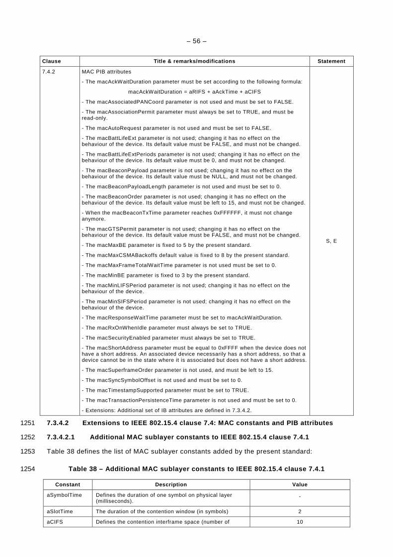
– 56 –
Clause Title & remarks/modifications Statement
7.4.2 MAC PIB attributes
- The macAckWaitDuration parameter must be set according to the following formula:
macAckWaitDuration = aRIFS + aAckTime + aCIFS
- The macAssociatedPANCoord parameter is not used and must be set to FALSE.
- The macAssociationPermit parameter must always be set to TRUE, and must be read-only.
- The macAutoRequest parameter is not used and must be set to FALSE.
- The macBattLifeExt parameter is not used; changing it has no effect on the behaviour of the device. Its default value must be FALSE, and must not be changed.
- The macBattLifeExtPeriods parameter is not used; changing it has no effect on the behaviour of the device. Its default value must be 0, and must not be changed.
- The macBeaconPayload parameter is not used; changing it has no effect on the behaviour of the device. Its default value must be NULL, and must not be changed.
- The macBeaconPayloadLength parameter is not used and must be set to 0.
- The macBeaconOrder parameter is not used; changing it has no effect on the behaviour of the device. Its default value must be left to 15, and must not be changed.
- When the macBeaconTxTime parameter reaches 0xFFFFFF, it must not change anymore.
- The macGTSPermit parameter is not used; changing it has no effect on the behaviour of the device. Its default value must be FALSE, and must not be changed.
- The macMaxBE parameter is fixed to 5 by the present standard.
- The macMaxCSMABackoffs default value is fixed to 8 by the present standard.
- The macMaxFrameTotalWaitTime parameter is not used must be set to 0.
- The macMinBE parameter is fixed to 3 by the present standard.
- The macMinLIFSPeriod parameter is not used; changing it has no effect on the behaviour of the device.
- The macMinSIFSPeriod parameter is not used; changing it has no effect on the behaviour of the device.
- The macResponseWaitTime parameter must be set to macAckWaitDuration.
- The macRxOnWhenIdle parameter must always be set to TRUE.
- The macSecurityEnabled parameter must always be set to TRUE.
- The macShortAddress parameter must be equal to 0xFFFF when the device does not have a short address. An associated device necessarily has a short address, so that a device cannot be in the state where it is associated but does not have a short address.
- The macSuperframeOrder parameter is not used, and must be left to 15.
- The macSyncSymbolOffset is not used and must be set to 0.
- The macTimestampSupported parameter must be set to TRUE.
- The macTransactionPersistenceTime parameter is not used and must be set to 0.
- Extensions: Additional set of IB attributes are defined in 7.3.4.2.
S, E
7.3.4.2 Extensions to IEEE 802.15.4 clause 7.4: MAC constants and PIB attributes 1251
7.3.4.2.1 Additional MAC sublayer constants to IEEE 802.15.4 clause 7.4.1 1252
Table 38 defines the list of MAC sublayer constants added by the present standard: 1253
Table 38 – Additional MAC sublayer constants to IEE E 802.15.4 clause 7.4.1 1254
Constant Description Value
aSymbolTime Defines the duration of one symbol on physical layer (milliseconds).
-
aSlotTime The duration of the contention window (in symbols) 2
aCIFS Defines the contention interframe space (number of 10
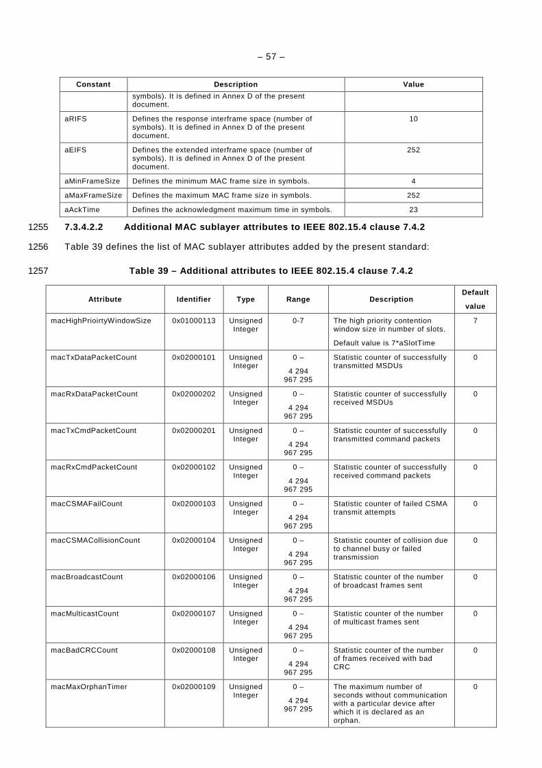
– 57 –
Constant Description Value
symbols). It is defined in Annex D of the present document.
aRIFS Defines the response interframe space (number of symbols). It is defined in Annex D of the present document.
10
aEIFS Defines the extended interframe space (number of symbols). It is defined in Annex D of the present document.
252
aMinFrameSize Defines the minimum MAC frame size in symbols. 4
aMaxFrameSize Defines the maximum MAC frame size in symbols. 252
aAckTime Defines the acknowledgment maximum time in symbols. 23
7.3.4.2.2 Additional MAC sublayer attributes to IEE E 802.15.4 clause 7.4.2 1255
Table 39 defines the list of MAC sublayer attributes added by the present standard: 1256
Table 39 – Additional attributes to IEEE 802.15.4 c lause 7.4.2 1257
Attribute Identifier Type Range Description Default
value
macHighPrioirtyWindowSize 0x01000113 Unsigned Integer
0-7 The high priority contention window size in number of slots.
Default value is 7*aSlotTime
7
macTxDataPacketCount 0x02000101 Unsigned Integer
0 –
4 294 967 295
Statistic counter of successfully transmitted MSDUs
0
macRxDataPacketCount 0x02000202 Unsigned Integer
0 –
4 294 967 295
Statistic counter of successfully received MSDUs
0
macTxCmdPacketCount 0x02000201 Unsigned Integer
0 –
4 294 967 295
Statistic counter of successfully transmitted command packets
0
macRxCmdPacketCount 0x02000102 Unsigned Integer
0 –
4 294 967 295
Statistic counter of successfully received command packets
0
macCSMAFailCount 0x02000103 Unsigned Integer
0 –
4 294 967 295
Statistic counter of failed CSMA transmit attempts
0
macCSMACollisionCount 0x02000104 Unsigned Integer
0 –
4 294 967 295
Statistic counter of collision due to channel busy or failed transmission
0
macBroadcastCount 0x02000106 Unsigned Integer
0 –
4 294 967 295
Statistic counter of the number of broadcast frames sent
0
macMulticastCount 0x02000107 Unsigned Integer
0 –
4 294 967 295
Statistic counter of the number of multicast frames sent
0
macBadCRCCount 0x02000108 Unsigned Integer
0 –
4 294 967 295
Statistic counter of the number of frames received with bad CRC
0
macMaxOrphanTimer 0x02000109 Unsigned Integer
0 –
4 294 967 295
The maximum number of seconds without communication with a particular device after which it is declared as an orphan.
0
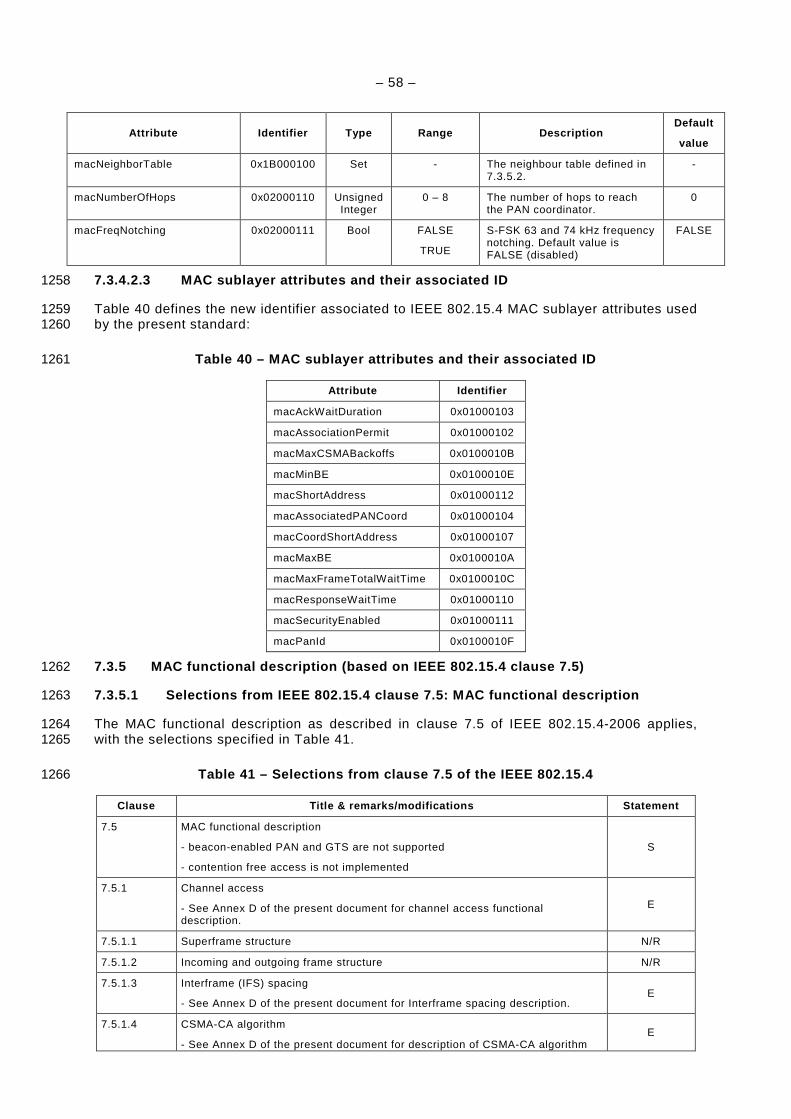
– 58 –
Attribute Identifier Type Range Description Default
value
macNeighborTable 0x1B000100 Set - The neighbour table defined in 7.3.5.2.
-
macNumberOfHops 0x02000110 Unsigned Integer
0 – 8 The number of hops to reach the PAN coordinator.
0
macFreqNotching 0x02000111 Bool FALSE
TRUE
S-FSK 63 and 74 kHz frequency notching. Default value is FALSE (disabled)
FALSE
7.3.4.2.3 MAC sublayer attributes and their associa ted ID 1258
Table 40 defines the new identifier associated to IEEE 802.15.4 MAC sublayer attributes used 1259 by the present standard: 1260
Table 40 – MAC sublayer attributes and their associ ated ID 1261
Attribute Identifier
macAckWaitDuration 0x01000103
macAssociationPermit 0x01000102
macMaxCSMABackoffs 0x0100010B
macMinBE 0x0100010E
macShortAddress 0x01000112
macAssociatedPANCoord 0x01000104
macCoordShortAddress 0x01000107
macMaxBE 0x0100010A
macMaxFrameTotalWaitTime 0x0100010C
macResponseWaitTime 0x01000110
macSecurityEnabled 0x01000111
macPanId 0x0100010F
7.3.5 MAC functional description (based on IEEE 802 .15.4 clause 7.5) 1262
7.3.5.1 Selections from IEEE 802.15.4 clause 7.5: M AC functional description 1263
The MAC functional description as described in clause 7.5 of IEEE 802.15.4-2006 applies, 1264 with the selections specified in Table 41. 1265
Table 41 – Selections from clause 7.5 of the IEEE 8 02.15.4 1266
Clause Title & remarks/modifications Statement
7.5 MAC functional description
- beacon-enabled PAN and GTS are not supported
- contention free access is not implemented
S
7.5.1 Channel access
- See Annex D of the present document for channel access functional description.
E
7.5.1.1 Superframe structure N/R
7.5.1.2 Incoming and outgoing frame structure N/R
7.5.1.3 Interframe (IFS) spacing
- See Annex D of the present document for Interframe spacing description. E
7.5.1.4 CSMA-CA algorithm
- See Annex D of the present document for description of CSMA-CA algorithm E
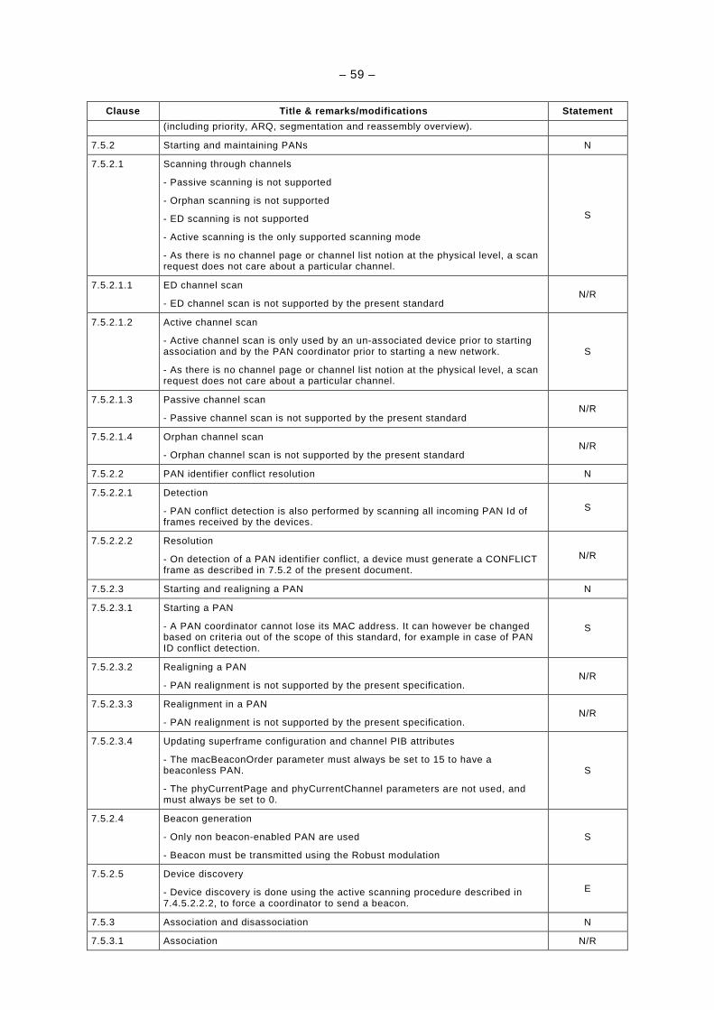
– 59 –
Clause Title & remarks/modifications Statement
(including priority, ARQ, segmentation and reassembly overview).
7.5.2 Starting and maintaining PANs N
7.5.2.1 Scanning through channels
- Passive scanning is not supported
- Orphan scanning is not supported
- ED scanning is not supported
- Active scanning is the only supported scanning mode
- As there is no channel page or channel list notion at the physical level, a scan request does not care about a particular channel.
S
7.5.2.1.1 ED channel scan
- ED channel scan is not supported by the present standard N/R
7.5.2.1.2 Active channel scan
- Active channel scan is only used by an un-associated device prior to starting association and by the PAN coordinator prior to starting a new network.
- As there is no channel page or channel list notion at the physical level, a scan request does not care about a particular channel.
S
7.5.2.1.3 Passive channel scan
- Passive channel scan is not supported by the present standard N/R
7.5.2.1.4 Orphan channel scan
- Orphan channel scan is not supported by the present standard N/R
7.5.2.2 PAN identifier conflict resolution N
7.5.2.2.1 Detection
- PAN conflict detection is also performed by scanning all incoming PAN Id of frames received by the devices.
S
7.5.2.2.2 Resolution
- On detection of a PAN identifier conflict, a device must generate a CONFLICT frame as described in 7.5.2 of the present document.
N/R
7.5.2.3 Starting and realigning a PAN N
7.5.2.3.1 Starting a PAN
- A PAN coordinator cannot lose its MAC address. It can however be changed based on criteria out of the scope of this standard, for example in case of PAN ID conflict detection.
S
7.5.2.3.2 Realigning a PAN
- PAN realignment is not supported by the present specification. N/R
7.5.2.3.3 Realignment in a PAN
- PAN realignment is not supported by the present specification. N/R
7.5.2.3.4 Updating superframe configuration and channel PIB attributes
- The macBeaconOrder parameter must always be set to 15 to have a beaconless PAN.
- The phyCurrentPage and phyCurrentChannel parameters are not used, and must always be set to 0.
S
7.5.2.4 Beacon generation
- Only non beacon-enabled PAN are used
- Beacon must be transmitted using the Robust modulation
S
7.5.2.5 Device discovery
- Device discovery is done using the active scanning procedure described in 7.4.5.2.2.2, to force a coordinator to send a beacon.
E
7.5.3 Association and disassociation N
7.5.3.1 Association N/R
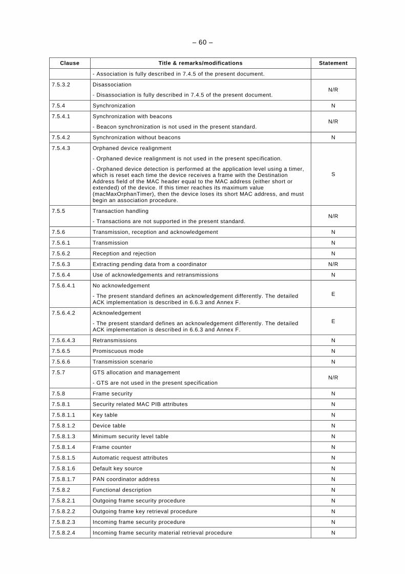
– 60 –
Clause Title & remarks/modifications Statement
- Association is fully described in 7.4.5 of the present document.
7.5.3.2 Disassociation
- Disassociation is fully described in 7.4.5 of the present document. N/R
7.5.4 Synchronization N
7.5.4.1 Synchronization with beacons
- Beacon synchronization is not used in the present standard. N/R
7.5.4.2 Synchronization without beacons N
7.5.4.3 Orphaned device realignment
- Orphaned device realignment is not used in the present specification.
- Orphaned device detection is performed at the application level using a timer, which is reset each time the device receives a frame with the Destination Address field of the MAC header equal to the MAC address (either short or extended) of the device. If this timer reaches its maximum value (macMaxOrphanTimer), then the device loses its short MAC address, and must begin an association procedure.
S
7.5.5 Transaction handling
- Transactions are not supported in the present standard. N/R
7.5.6 Transmission, reception and acknowledgement N
7.5.6.1 Transmission N
7.5.6.2 Reception and rejection N
7.5.6.3 Extracting pending data from a coordinator N/R
7.5.6.4 Use of acknowledgements and retransmissions N
7.5.6.4.1 No acknowledgement
- The present standard defines an acknowledgement differently. The detailed ACK implementation is described in 6.6.3 and Annex F.
E
7.5.6.4.2 Acknowledgement
- The present standard defines an acknowledgement differently. The detailed ACK implementation is described in 6.6.3 and Annex F.
E
7.5.6.4.3 Retransmissions N
7.5.6.5 Promiscuous mode N
7.5.6.6 Transmission scenario N
7.5.7 GTS allocation and management
- GTS are not used in the present specification N/R
7.5.8 Frame security N
7.5.8.1 Security related MAC PIB attributes N
7.5.8.1.1 Key table N
7.5.8.1.2 Device table N
7.5.8.1.3 Minimum security level table N
7.5.8.1.4 Frame counter N
7.5.8.1.5 Automatic request attributes N
7.5.8.1.6 Default key source N
7.5.8.1.7 PAN coordinator address N
7.5.8.2 Functional description N
7.5.8.2.1 Outgoing frame security procedure N
7.5.8.2.2 Outgoing frame key retrieval procedure N
7.5.8.2.3 Incoming frame security procedure N
7.5.8.2.4 Incoming frame security material retrieval procedure N

– 61 –
Clause Title & remarks/modifications Statement
7.5.8.2.5 KeyDescriptor lookup table N
7.5.8.2.6 Blacklist checking procedure N
7.5.8.2.7 DeviceDescriptor lookup procedure N
7.5.8.2.8 Incoming security level checking procedure N
7.5.8.2.9 Incoming key usage policy checking procedure N
7.3.5.2 Extensions to IEEE 802.15.4 clause 7.5: Nei ghbour Table 1267
Every device must maintain a Neighbour Table, which contains information about all the 1268 devices within the POS of a device. This table is actualized each time any frame is received 1269 from a neighbouring device, and each time a Tone Map Response command is received. This 1270 table must be accessible by the Adaptation, MAC sublayers and physical layer. Each entry of 1271 this table contains the fields listed in Table 42: 1272
Table 42 – Neighbour Table 1273
Field Name Size/Type Description
ToneMap 9 bits The Tone Map parameter defines which frequency sub-band can be used for communication with the device. A bit set to 1 means that the frequency sub-band can be used, and a bit set to 0 means that frequency sub-band must not be used.
Modulation 2 bits Defines the modulation type to use for communicating with the device.
0x00: Robust
0x01: DBPSK
0x02: DQPSK
0x03: D8PSK
TxGain 4 bits Defines the Tx Gain to use to transmit frames to that device
TxRes 1 bit Defines the Tx Gain resolution corresponding to one gain step.
0 : 6 dB
1 : 3 dB
TxCoeff 8 x 4 bits The Tx gain for each 10 kHz-wide spectrum band
LQI 8 bits Link Quality Indicator
Age 8 bits The remaining lifetime of the device in minutes.
- When the entry is created, this value must be set to the default value 0;
- When it reaches 0, a Tone Map request may be issued if data is sent to this device. Upon successful reception of a tone map response, this value is set to adpMaxAgeTime.
IsNeighbour 8 bits Indicate either the device is a neighbour or not.
If the device receives a frame whose source address field (MAC sublayer header) does not 1274 exist in the neighbour table, it must add a new entry for that device with the following default 1275 values: 1276
– Modulation = 0 (Robust); 1277
– ToneMap = (all bits set to 1) AND (adpToneMask); 1278
– TxGain = 0b0000; 1279
– TxCoeff = 0xFFFFFFFF; 1280
– LQI = 0; 1281
– Age = 0. 1282

– 62 –
The Neighbour Table is available in the Information Base under the attribute 1283 macNeighborTable (see 7.3.4.2.2). 1284
7.3.6 MAC security suite specifications (selections from IEEE 802.15.4 clause 7.6) 1285
The security suite specifications as described in clause 7.6 of IEEE 802.15.4-2006 apply, with 1286 the selections specified in Table 43. 1287
Table 43 – Selections from clause 7.6 of the IEEE 8 02.15.4 1288
Clause Title & remarks/modifications Statement
7.6 Security suite specification N
7.6.1 PIB security material N
7.6.2 Auxiliary security header N
7.6.2.1 Integer and octet representation N
7.6.2.2 Security Control field N
7.6.2.2.1 Security Level subfield
- Two values are allowed by the present standard:
0x00 = "none",
0x05 = "ENC-MIC-32".
S
7.6.2.2.2 Key Identifier Mode subfield
- One Key Identifier Mode is allowed by the present standard:
0x01 = "Key determined from the 1-octet Key Index subfield"
The number of keys is limited to 4 (range = 0-3)
S
7.6.2.3 Frame Counter field N
7.6.2.4 Key Identifier field N
7.6.2.4.1 Key Source subfield N/R
7.6.2.4.2 Key Index subfield N
7.6.3 Security operations N
7.6.3.1 Integer and octet representation N
7.6.3.2 CCM* Nonce N
7.6.3.3 CCM* prerequisites N
7.6.3.3.1 Authentication field length N
7.6.3.4 CCM* transformation data representation N
7.6.3.4.1 Key and nonce data inputs N
7.6.3.4.2 a data and m data
- Two values are allowed by the present standard:
0x00 = "none",
0x05 = "ENC-MIC-32".
S
7.6.3.4.3 c data output
- Two values are allowed by the present standard:
0x00 = "none",
0x05 = "ENC-MIC-32".
S
7.6.3.5 CCM* inverse transformation data representation N
7.6.3.5.1 Key and nonce data inputs N
7.6.3.5.2 c data and a data N
7.6.3.5.3 m data output N
1289
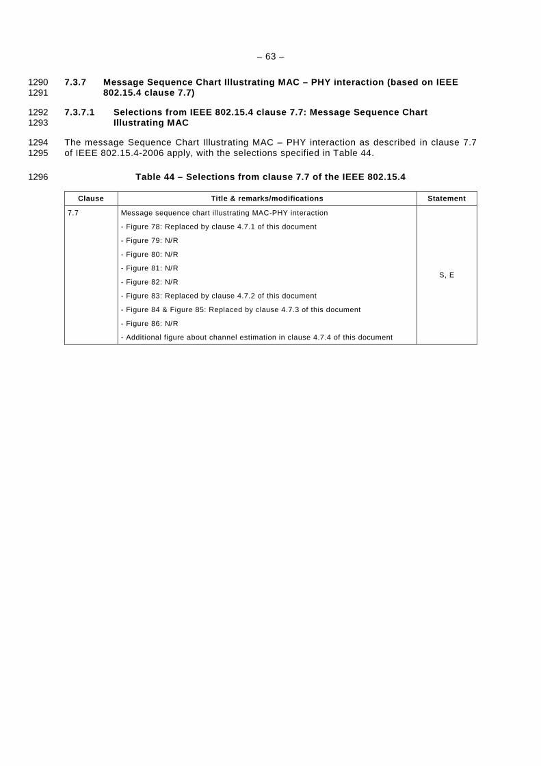
– 63 –
7.3.7 Message Sequence Chart Illustrating MAC – PHY interaction (based on IEEE 1290 802.15.4 clause 7.7) 1291
7.3.7.1 Selections from IEEE 802.15.4 clause 7.7: M essage Sequence Chart 1292 Illustrating MAC 1293
The message Sequence Chart Illustrating MAC – PHY interaction as described in clause 7.7 1294 of IEEE 802.15.4-2006 apply, with the selections specified in Table 44. 1295
Table 44 – Selections from clause 7.7 of the IEEE 8 02.15.4 1296
Clause Title & remarks/modifications Statement
7.7 Message sequence chart illustrating MAC-PHY interaction
- Figure 78: Replaced by clause 4.7.1 of this document
- Figure 79: N/R
- Figure 80: N/R
- Figure 81: N/R
- Figure 82: N/R
- Figure 83: Replaced by clause 4.7.2 of this document
- Figure 84 & Figure 85: Replaced by clause 4.7.3 of this document
- Figure 86: N/R
- Additional figure about channel estimation in clause 4.7.4 of this document
S, E
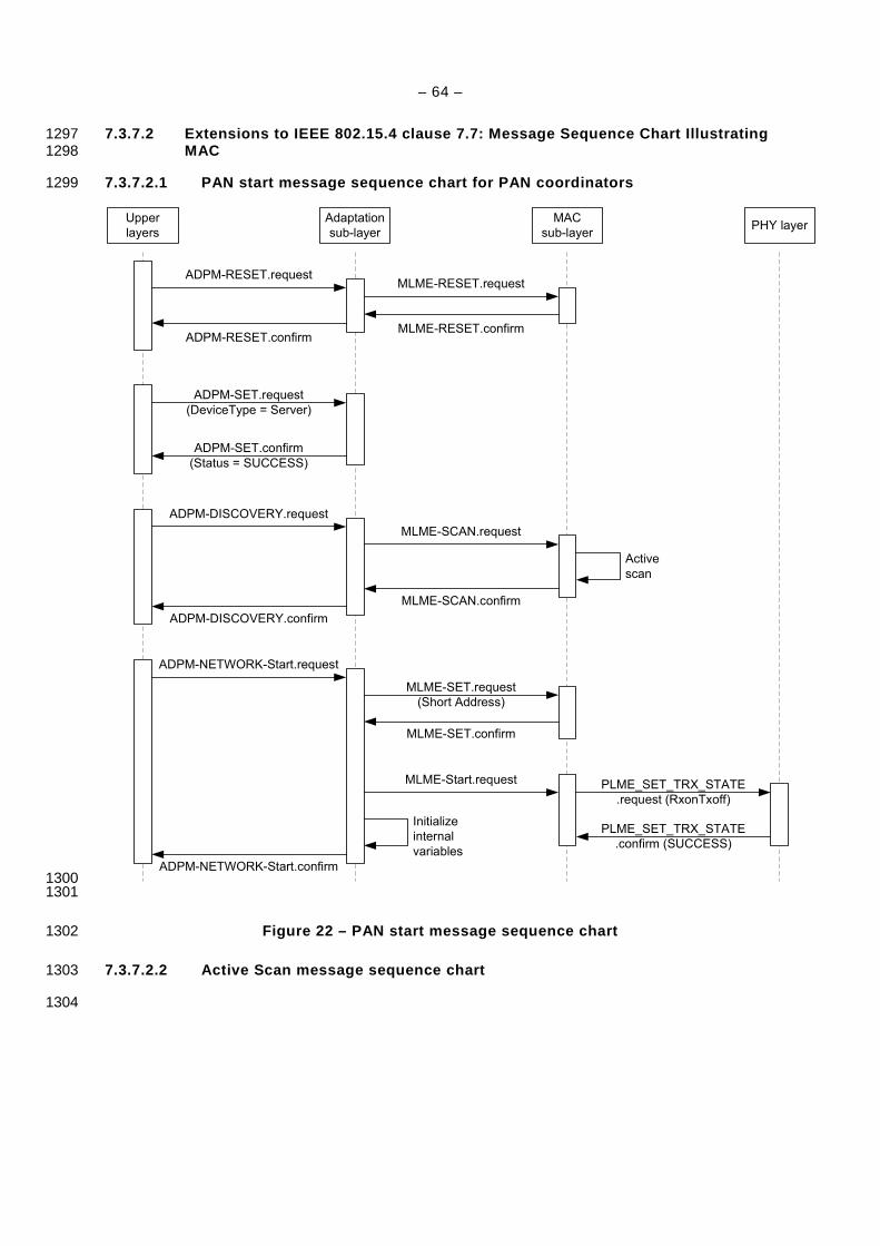
– 64 –
7.3.7.2 Extensions to IEEE 802.15.4 clause 7.7: Mes sage Sequence Chart Illustrating 1297 MAC 1298
7.3.7.2.1 PAN start message sequence chart for PAN coordinators 1299
Upper
layers
Adaptation
sub-layer
MAC
sub-layerPHY layer
ADPM-RESET.requestMLME-RESET.request
MLME-RESET.confirmADPM-RESET.confirm
ADPM-SET.confirm
(Status = SUCCESS)
ADPM-SET.request
(DeviceType = Server)
ADPM-DISCOVERY.request
MLME-SCAN.request
MLME-SCAN.confirm
ADPM-DISCOVERY.confirm
Active
scan
ADPM-NETWORK-Start.request
MLME-SET.request
(Short Address)
MLME-SET.confirm
ADPM-NETWORK-Start.confirm
MLME-Start.request PLME_SET_TRX_STATE
.request (RxonTxoff)
PLME_SET_TRX_STATE
.confirm (SUCCESS)
Initialize
internal
variables
1300 1301
Figure 22 – PAN start message sequence chart 1302
7.3.7.2.2 Active Scan message sequence chart 1303
1304
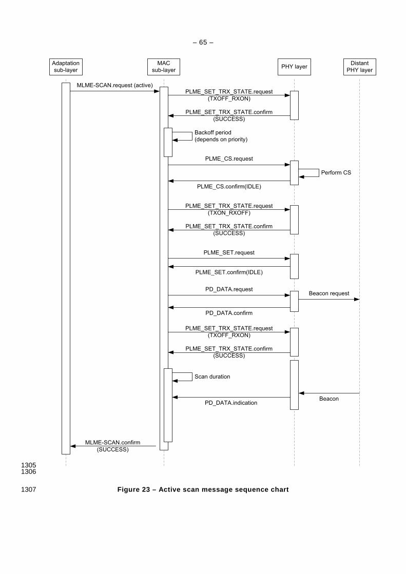
– 65 –
Adaptation
sub-layer
MAC
sub-layerPHY layer
Distant
PHY layer
MLME-SCAN.request (active)
PLME_CS.request
PLME_CS.confirm(IDLE)
Backoff period
(depends on priority)
MLME-SCAN.confirm
(SUCCESS)
PLME_SET_TRX_STATE.request
(TXOFF_RXON)
PLME_SET_TRX_STATE.confirm
(SUCCESS)
Perform CS
PLME_SET_TRX_STATE.request
(TXON_RXOFF)
PLME_SET_TRX_STATE.confirm
(SUCCESS)
PLME_SET.request
PLME_SET.confirm(IDLE)
PD_DATA.request
PD_DATA.confirm
Beacon request
PLME_SET_TRX_STATE.request
(TXOFF_RXON)
PLME_SET_TRX_STATE.confirm
(SUCCESS)
Scan duration
BeaconPD_DATA.indication
1305 1306
Figure 23 – Active scan message sequence chart 1307
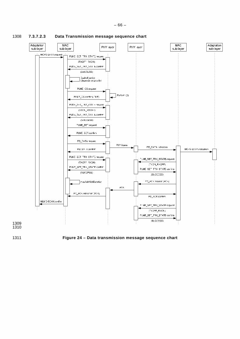
– 66 –
7.3.7.2.3 Data Transmission message sequence chart 1308
1309 1310
Figure 24 – Data transmission message sequence char t 1311
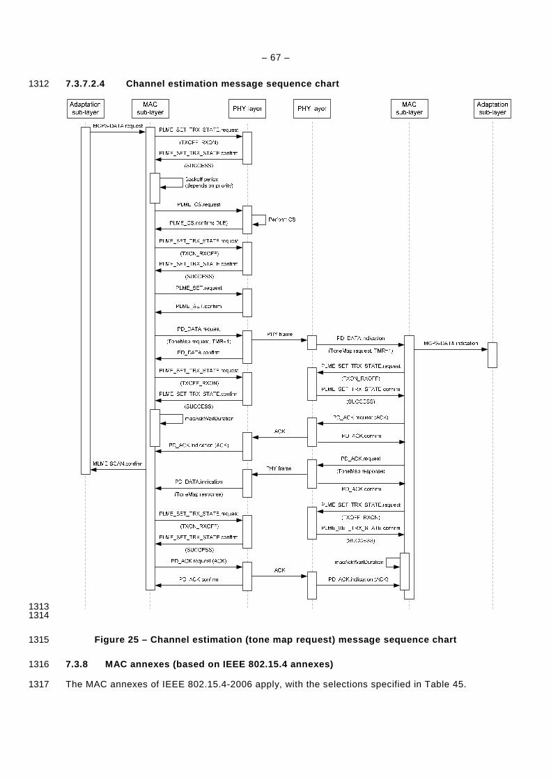
– 67 –
7.3.7.2.4 Channel estimation message sequence chart 1312
1313 1314
Figure 25 – Channel estimation (tone map request) m essage sequence chart 1315
7.3.8 MAC annexes (based on IEEE 802.15.4 annexes) 1316
The MAC annexes of IEEE 802.15.4-2006 apply, with the selections specified in Table 45. 1317
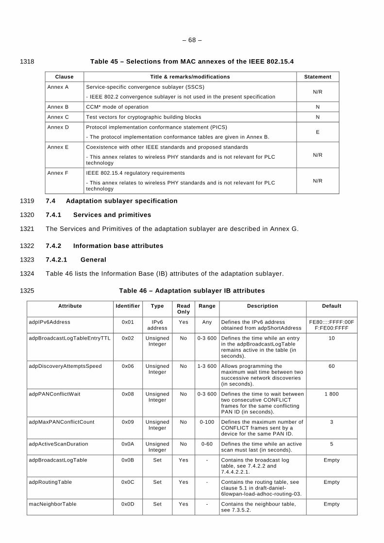
– 68 –
Table 45 – Selections from MAC annexes of the IEEE 802.15.4 1318
Clause Title & remarks/modifications Statement
Annex A Service-specific convergence sublayer (SSCS)
- IEEE 802.2 convergence sublayer is not used in the present specification N/R
Annex B CCM* mode of operation N
Annex C Test vectors for cryptographic building blocks N
Annex D Protocol implementation conformance statement (PICS)
- The protocol implementation conformance tables are given in Annex B. E
Annex E Coexistence with other IEEE standards and proposed standards
- This annex relates to wireless PHY standards and is not relevant for PLC technology
N/R
Annex F IEEE 802.15.4 regulatory requirements
- This annex relates to wireless PHY standards and is not relevant for PLC technology
N/R
7.4 Adaptation sublayer specification 1319
7.4.1 Services and primitives 1320
The Services and Primitives of the adaptation sublayer are described in Annex G. 1321
7.4.2 Information base attributes 1322
7.4.2.1 General 1323
Table 46 lists the Information Base (IB) attributes of the adaptation sublayer. 1324
Table 46 – Adaptation sublayer IB attributes 1325
Attribute Identifier Type Read Only
Range Description Default
adpIPv6Address 0x01 IPv6 address
Yes Any Defines the IPv6 address obtained from adpShortAddress
FE80::::FFFF:00FF:FE00:FFFF
adpBroadcastLogTableEntryTTL 0x02 Unsigned Integer
No 0-3 600 Defines the time while an entry in the adpBroadcastLogTable remains active in the table (in seconds).
10
adpDiscoveryAttemptsSpeed 0x06 Unsigned Integer
No 1-3 600 Allows programming the maximum wait time between two successive network discoveries (in seconds).
60
adpPANConflictWait 0x08 Unsigned Integer
No 0-3 600 Defines the time to wait between two consecutive CONFLICT frames for the same conflicting PAN ID (in seconds).
1 800
adpMaxPANConflictCount 0x09 Unsigned Integer
No 0-100 Defines the maximum number of CONFLICT frames sent by a device for the same PAN ID.
3
adpActiveScanDuration 0x0A Unsigned Integer
No 0-60 Defines the time while an active scan must last (in seconds).
5
adpBroadcastLogTable 0x0B Set Yes - Contains the broadcast log table, see 7.4.2.2 and 7.4.4.2.2.1.
Empty
adpRoutingTable 0x0C Set Yes - Contains the routing table, see clause 5.1 in draft-daniel-6lowpan-load-adhoc-routing-03.
Empty
macNeighborTable 0x0D Set Yes - Contains the neighbour table, see 7.3.5.2.
Empty
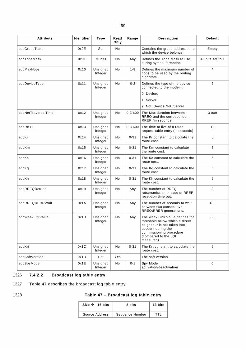
– 69 –
Attribute Identifier Type Read Only
Range Description Default
adpGroupTable 0x0E Set No - Contains the group addresses to which the device belongs.
Empty
adpToneMask 0x0F 70 bits No Any Defines the Tone Mask to use during symbol formation
All bits set to 1
adpMaxHops 0x10 Unsigned Integer
No 1-8 Defines the maximum number of hops to be used by the routing algorithm.
4
adpDeviceType 0x11 Unsigned Integer
No 0-2 Defines the type of the device connected to the modem:
0: Device,
1: Server,
2: Not_Device,Not_Server
2
adpNetTraversalTime 0x12 Unsigned Integer
No 0-3 600 The Max duration between RREQ and the correspondent RREP (in seconds)
3 000
adpRrtTtl 0x13 Unsigned Integer
No 0-3 600 The time to live of a route request table entry (in seconds)
10
adpKr 0x14 Unsigned Integer
No 0-31 The Kr constant to calculate the route cost.
6
adpKm 0x15 Unsigned Integer
No 0-31 The Km constant to calculate the route cost.
5
adpKc 0x16 Unsigned Integer
No 0-31 The Kc constant to calculate the route cost.
5
adpKq 0x17 Unsigned Integer
No 0-31 The Kq constant to calculate the route cost.
5
adpKh 0x18 Unsigned Integer
No 0-31 The Kh constant to calculate the route cost.
5
adpRREQRetries 0x19 Unsigned Integer
No Any The number of RREQ retransmission in case of RREP reception time out.
3
adpRREQRERRWait 0x1A Unsigned Integer
No Any The number of seconds to wait between two consecutive RREQ\RRER generations.
400
adpWeakLQIValue 0x1B Unsigned Integer
No Any The weak Link Value defines the threshold below which a direct neighbour is not taken into account during the commissioning procedure (compared to the LQI measured).
63
adpKrt 0x1C Unsigned Integer
No 0-31 The Krt constant to calculate the route cost.
5
adpSoftVersion 0x1D Set Yes - The soft version -
adpSpyMode 0x1E Unsigned Integer
No 0-1 Spy Mode activation/deactivation
0
7.4.2.2 Broadcast log table entry 1326
Table 47 describes the broadcast log table entry: 1327
Table 47 – Broadcast log table entry 1328
Size 16 bits 8 bits 13 bits
Source Address Sequence Number TTL

– 70 –
7.4.3 Data frame format, datagram transmission and addressing (based on RFC 4944) 1329
7.4.3.1 Selections from RFC 4944 1330
The data frame format, the theory of operation for datagram transmission using the IEEE 1331 802.15.4 MAC sublayer, and the addressing scheme as specified in RFC 4944 together with 1332 the selections listed in Table 48. 1333
Table 48 – Selections from RFC 4944 1334
Clause Title & remarks/modifications Statement
1. Introduction N
1.1. Requirements Notation N
1.2. Terms Used N
2. IEEE 802.15.4 Mode for IP
- Data frames should always be acknowledged
- Only non beacon-enabled network are used
S
3. Addressing Modes
- IPv6 prefixes learning via router advertisements is not supported S
4. Maximum Transmission Unit N
5. LoWPAN Adaptation Layer and Frame Format
- Extension: additional Command Frame header: see 7.4.3.2.1.
- When more than one LoWPAN header is used in the same packet, they MUST appear in the following order:
Mesh Addressing Header
Broadcast Header
Fragmentation Header
Command Frame Header (see 7.4.3.2.1)
E
5.1. Dispatch Type and Header N
5.2. Mesh Addressing Type and Header
- The value of the HopsLeft field must not exceed adpMaxHops (see 7.4.2.1). S
5.3. Fragmentation Type and Header N
6. Stateless Address Autoconfiguration
- The Interface Identifier (see RFC 4291) for an IEEE 802.15.4 interface MUST be based on the EUI-64 identifier assigned to the device, the latest being itself based on a EUI-48.
- Additional care must be taken when choosing a PAN identifier, so that not to interfere with I/G and U/L bits of the interface identifier. If the PAN identifiers are chosen randomly, then should be logically ANDed with 0xFCFF
S
7. IPv6 Link Local Address N
8. Unicast Address Mapping N
9. Multicast Address Mapping N
10. Header Compression N
10.1. Encoding of IPv6 Header Fields N
10.2. Encoding of UDP Header Fields N
10.3. Non-Compressed Fields N
10.3.1. Non-Compressed IPv6 Fields N
10.3.2. Non-Compressed and Partially Compressed UDP Fields N
11. Frame Delivery in a Link-Layer Mesh
- All devices must be FFD S
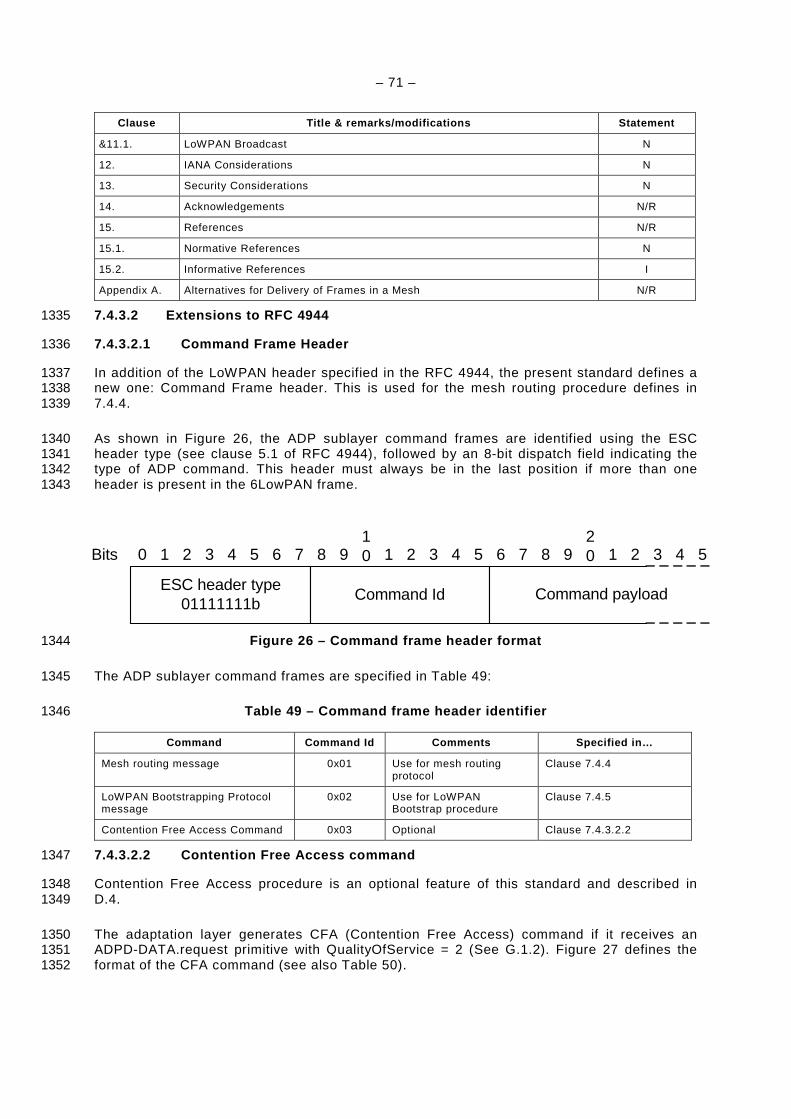
– 71 –
Clause Title & remarks/modifications Statement
&11.1. LoWPAN Broadcast N
12. IANA Considerations N
13. Security Considerations N
14. Acknowledgements N/R
15. References N/R
15.1. Normative References N
15.2. Informative References I
Appendix A. Alternatives for Delivery of Frames in a Mesh N/R
7.4.3.2 Extensions to RFC 4944 1335
7.4.3.2.1 Command Frame Header 1336
In addition of the LoWPAN header specified in the RFC 4944, the present standard defines a 1337 new one: Command Frame header. This is used for the mesh routing procedure defines in 1338 7.4.4. 1339
As shown in Figure 26, the ADP sublayer command frames are identified using the ESC 1340 header type (see clause 5.1 of RFC 4944), followed by an 8-bit dispatch field indicating the 1341 type of ADP command. This header must always be in the last position if more than one 1342 header is present in the 6LowPAN frame. 1343
Figure 26 – Command frame header format 1344
The ADP sublayer command frames are specified in Table 49: 1345
Table 49 – Command frame header identifier 1346
Command Command Id Comments Specified in…
Mesh routing message 0x01 Use for mesh routing protocol
Clause 7.4.4
LoWPAN Bootstrapping Protocol message
0x02 Use for LoWPAN Bootstrap procedure
Clause 7.4.5
Contention Free Access Command 0x03 Optional Clause 7.4.3.2.2
7.4.3.2.2 Contention Free Access command 1347
Contention Free Access procedure is an optional feature of this standard and described in 1348 D.4. 1349
The adaptation layer generates CFA (Contention Free Access) command if it receives an 1350 ADPD-DATA.request primitive with QualityOfService = 2 (See G.1.2). Figure 27 defines the 1351 format of the CFA command (see also Table 50). 1352
0 54321109876 54321 9876
20 54321
ESC header type01111111b
Command Id
Bits
Command payload

– 72 –
1353 Figure 27 – CFA command format 1354
Table 50 – CFA value field description 1355
CFA value Description
0 Request to allow a transmission during contention free slot
1 Request to stop a transmission during contention free slot
2 Response with SUCCESS
3 Response with FAIL
The network coordinator may always use a contention free slot for transmission if other 1356 devices are not allowed to use it the same time. Other devices must ask the network 1357 coordinator for permission to use a contention free slot (CFS) for transmission by sending 1358 CFA command with request. The network coordinator may allow requested device to use a 1359 CFS for transmission by sending a confirmation response. After receiving a successful 1360 response from the network coordinator requested device can start a transmission during CFS. 1361 If the network coordinator denies a request the device should not use a CFS for transmission. 1362 The requested device must send a request to stop using CFS when it is done with contention 1363 free transmission. 1364
Priority management can be performed using the “Normal” and “High” priority values for QOS 1365 parameter of MCPS-DATA.request primitive. 1366
7.4.4 Mesh Routing (based on draft-daniel-6lowpan-l oad-adhoc-routing-03) 1367
7.4.4.1 Selections from draft-daniel-6lowpan-load-a dhoc-routing-03 1368
The mesh routing as described in draft-daniel-6lowpan-load-adhoc-routing-03 applies, with 1369 the selections specified in Table 51. 1370
Table 51 – Selections from draft-daniel-6lowpan-loa d-adhoc-routing-03 1371
Clause Title & remarks/modifications Statement
1. Introduction N
2. Requirements notation N
3. Overview
- Routing is only permitted with 16-bit addresses,
- LOAD uses the route cost described in Annex C as a metric of routing.
S,E
4. Terminology N
5. Data Structures N
5.1 Routing Table Entry
- The destination address must be a 16-bit address,
- The next hop address must be a 16-bit address,
- The routing table is stored in the IB under the attribute adpRoutingTable.
S, E
5.2 Route Request Table Entry
- The originator address must be a 16-bit address,
- The reverse route address must be a 16-bit address.
S

– 73 –
Clause Title & remarks/modifications Statement
5.3 Message Format
- For path discovery procedure, two messages have been added: Path Request (PREQ) and Path Reply (PREP). See 7.4.4.2.4.
E
5.3.1 Route Request (RREQ)
- The CT field must be equal to 0x0F, to specify the use of the route cost described in Annex C,
- The D bit must be set to 1,
- The O bit must be set to 1,
- The link layer destination and originator address must be 16-bit addresses.
S
5.3.2 Route Reply (RREP)
- The CT field must be equal to 0x0F, to specify the use of the route cost described in Annex C,
- The D bit must be set to 1,
- The O bit must be set to 1,
- The link layer destination and originator address must be 16-bit addresses.
S
5.3.3 Route Error (RERR)
- The D bit must be set to 1,
- The O bit must be set to 1,
- The unreachable address must be 16-bit addresses.
S
6. Operation N
6.1 Generating Route Request N
6.2 Processing and Forwarding Route Request N
6.3 Generating Route Reply N
6.4 Receiving and Forwarding Route Reply N
6.5 Local Repair and RERR
- If a link break occurs or a device fails during the delivery of data packets, the upstream node of the link break MUST repair the route locally, and execute the repairing procedure described in the present clause.
S
7. Configuration Parameters
- The values of the configuration parameters must be:
NET_TRAVERSAL_TIME = 4 000
RREQ_RETRIES = 3
WEAK_LQI_VALUE = 63
- Extension: the following parameters are added by the present standard:
RREQ_RERR_WAIT = 2s
PATH_DISCOVERY_TIME = 1 000
S, E
8. IANA Consideration N
9. Security Considerations N/R
10. Acknowledgments N/R
11. References N
11.1 Normative Reference N
11.2 Informative Reference I
7.4.4.2 Extensions to draft-daniel-6lowpan-load-adh oc-routing-03 1372
7.4.4.2.1 Unicast Packet Routing 1373
The routing of unicast packet is performed using the following algorithm on reception of a 1374 MCPS-DATA.indication from the MAC layer: 1375
– 74 –
IF (MAC destination address == address of device) 1376
IF (6LoWPAN destination address == 6LoWPAN address of device) 1377
– Generate an ADPD-DATA.indication primitive to indicate the arrival of a frame to 1378 the upper layer, with the following characteristics (see G.1.4): 1379
– DstAddrMode = 0x02 1380
– DstAddr = 6LoWPAN destination address 1381
– SrcAddr = The originator address in the 6LoWPAN mesh header 1382
– NsduLength = length of the payload 1383
– Nsdu = the payload 1384
– LinkQualityIndicator = msduLinkQuality (see G.3.2) 1385
– SecurityEnabled = (SecurityLevel != 0) 1386
ELSE IF (6LoWPAN destination address is in the neighbour table) 1387
– Forward the packet to the destination address, by invoking an MCPS-1388 DATA.request primitive with the destination address set to the final destination 1389 address 1390
ELSE IF (6LoWPAN destination address is in the routing table and next hop in the 1391 neighbour table) 1392
– Forward the packet to the next hop found in the routing table, by invoking an 1393 MCPS-DATA.request primitive, and using the communication parameters to that 1394 device contained in the neighbour table. 1395
ELSE IF (6LoWPAN Destination Address not in routing table) 1396
– Perform a link repair as described in clause 6.5 of draft-daniel-6lowpan-load-1397 adhoc-routing-03 1398
– Queue the packet for a sending retry 1399
ELSE 1400
– Drop the frame 1401
ELSE IF (MAC Destination address == 0xFFFF) 1402
– This is a broadcast frame: execute algorithm described in clause 7.4.4.2.2 of the 1403 present document 1404
ELSE 1405
– Drop the frame 1406
7.4.4.2.2 Multicast / Broadcast 1407
7.4.4.2.2.1 Packet Routing 1408
The packet routing mechanism is based on clause 11.1 of RFC 4944. This clause details more 1409 precisely the routing of broadcast and multicast packets. 1410
As described in clause 11.1 of RFC 4944, each broadcast packet has a BC0 header 1411 containing a sequence number. Each time a node sends a broadcast packet, it must 1412 increment this sequence number. 1413
Each node must have a broadcast log table. This table is used for routing broadcast packets, 1414 and each entry contains the parameters described in Table 52: 1415
Table 52 – Broadcast log table 1416
Field Name Size Description
SrcAddr 2 bytes The 16-bit source address of a broadcast packet. This is the address of the broadcast initiator.
– 75 –
Field Name Size Description
SeqNumber Integer, 1 byte The sequence number contained in the BC0 header
TimeToLive Integer The remaining time to live of this entry in the Broadcast Log Table, in milliseconds.
Each time a device receives a broadcast address with a HopsLft field of mesh header (see 1417 clause 5.2 of RFC 4944) strictly greater than 0, it must check if an entry already exists in the 1418 broadcast log table having the same SrcAddr and SeqNumber. If an entry exists, the received 1419 frame is silently discarded. Else, a new entry is added in the table, and the TimeToLive field is 1420 initialized with the value adpBroadcastLogTableEntryTTL (see 7.4.2). When this value 1421 reaches 0, the entry is removed from the broadcast log table. 1422
When a device receives a broadcast frame, so that it has to create an entry in the broadcast 1423 log table, it must decrement its HopsLft field and trigger the emission of the received 1424 broadcast frame using CSMA/CA. The frame will then be sent as if it was a standard unicast 1425 frame using CSMA/CA. 1426
This can be summarized by the following algorithm, executed upon reception of a frame 1427 whose destination address is 0xFFFF: 1428
1429 IF (HopsLft == 0) 1430
– Discard frame and exit 1431
ELSE IF ((SrcAddr, SeqNumber) exists in broadcast log table) 1432
– Discard frame 1433
ELSE 1434
– Create one entry (SrcAddr, SeqNumber, adpBroadcastLogTableEntryTTL) in broadcast 1435 log table, with the corresponding frame characteristics. 1436
IF (final destination address = broadcast address) or (final destination address is found in 1437 adpGroupTable) 1438
– Generate an ADPD-DATA.indication primitive to upper layer with the following 1439 characteristics: 1440
– DstAddrMode = 0x01 1441
– DstAddr = Destination address in the 6LoWPAN mesh header (multicast or 1442 broadcast address) 1443
– SrcAddr = The originator address in the 6LoWPAN mesh header 1444
– NsduLength = length of the data 1445
– Nsdu = the data 1446
– LinkQualityIndicator = msduLinkQuality (see G.3.2) 1447
– SecurityEnabled = (SecurityLevel != 0) 1448
– Trigger the sending of the frame using CSMA/CA 1449
NOTE In case of a multicast address, the broadcast address 0xFFFF is used at the MAC level as mentioned in 1450 clause 3 of RFC 4944. Multicast frames are routed using the same algorithm as broadcast frames. 1451
The broadcast log table is available in the Information Base with the attribute 1452 adpBroadcastLogTable (see 7.4.2). 1453
7.4.4.2.2.2 Groups 1454
Each device can belong to one or more group of devices. The IB attribute adpGroupTable 1455 (see 7.4.2) stores a list of 16-bit group addresses. 1456
When the device receives a MAC broadcast message, and if the final destination address in 1457 the 6LoWPAN mesh header is equal to one of the 16-bit group addresses in adpGroupTable, 1458
– 76 –
then an ADPD-DATA.indication primitive is generated to the upper layer (as described in 1459 7.4.4.2.2.1). 1460
Groups can be added or removed from the adpGroupTable using ADPM-SET.request 1461 primitive. The size of this table is implementation specific, and must have at least one entry. 1462 The way groups are managed by upper layers is beyond the scope of this document. 1463
7.4.4.2.3 Route Discovery 1464
7.4.4.2.3.1 Manual Route Discovery 1465
A manual route discovery can be triggered by the upper layer, for maintenance or 1466 performance purposes. This is done through the invocation of the ADPM-ROUTE-1467 DISCOVERY.request primitive. The adaptation sublayer then generates a RREQ frame and 1468 executes the algorithms as described in 7.4.4.1. 1469
After the algorithm completes, the adaptation sublayer generates an ADPM-ROUTE-1470 DISCOVERY.confirm primitive with the corresponding status code, and eventually modify its 1471 routing table. 1472
Only one route discovery procedure can be processed in the same time. All other ADPM-1473 ROUTE-DISCOVERY.request will be ignored. 1474
All devices are required to handle RREQ, RREP and RERR frames as described in 7.4.4.1 1475 and must modify their routing tables accordingly. 1476
7.4.4.2.3.2 Automatic Route Discovery 1477
If an ADPD.DATA.request primitive is invoked with its DiscoverRoute parameter set to TRUE, 1478 and if no entry is available in the routing table for the device designated by DstAddr, then the 1479 adaptation layer generates a RREQ and executes the algorithms described in 7.4.4.1 in order 1480 to find a route to the destination. If the route discovery succeeds, then the data frame is send 1481 to the destination according to the newly discovered route. If the route discovery fails, then 1482 the adaptation layer must generate an ADPD-DATA.confirm primitive with the status code 1483 ROUTE_ERROR. 1484
If an ADPD.DATA.request primitive is invoked with its DiscoverRoute parameter set to 1485 FALSE, and if no entry is available in the routing table for the device designated by DstAddr, 1486 then the adaptation layer must generate an ADPD-DATA.confirm primitive with the status 1487 code ROUTE_ERROR. 1488
Route repairing procedures are described in 7.4.4.1. 1489
7.4.4.2.3.3 RREQ RERR Generation Frequency Limit 1490
A node must wait RREQ_RERR_WAIT second between two successive RREQ/RERR 1491 generations to limit the number of broadcast packet in the network. The definition of the 1492 RREQ_RERR_WAIT parameter is given in 7.4.4.1. 1493
7.4.4.2.4 Path Discovery 1494
7.4.4.2.4.1 Operation 1495
A path discovery can be triggered by the upper layers, for maintenance or performance 1496 purposes. This is done through the invocation of the ADPM-PATH-DISCOVERY.request 1497 primitive. The adaptation sublayer then generates a PREQ frame and executes the algorithms 1498 described in following sub-clauses. 1499
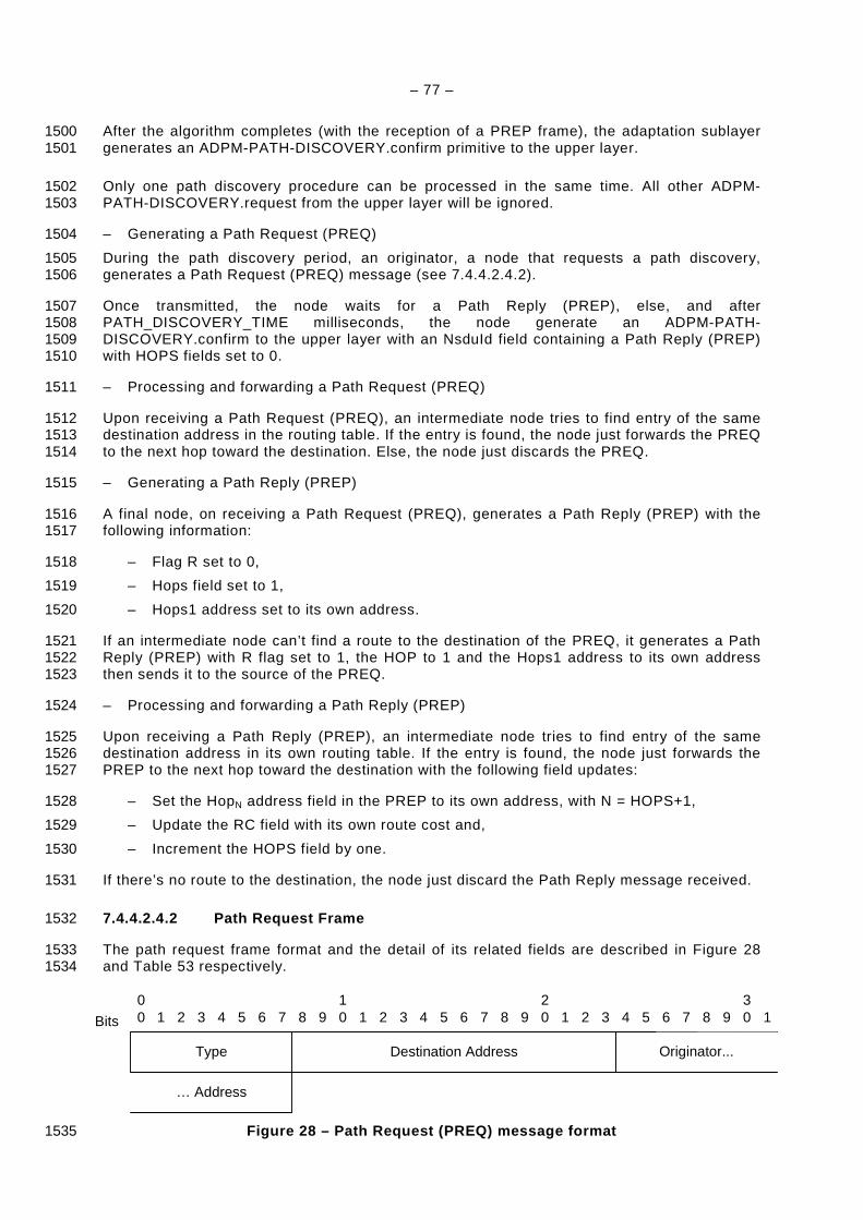
– 77 –
After the algorithm completes (with the reception of a PREP frame), the adaptation sublayer 1500 generates an ADPM-PATH-DISCOVERY.confirm primitive to the upper layer. 1501
Only one path discovery procedure can be processed in the same time. All other ADPM-1502 PATH-DISCOVERY.request from the upper layer will be ignored. 1503
– Generating a Path Request (PREQ) 1504
During the path discovery period, an originator, a node that requests a path discovery, 1505 generates a Path Request (PREQ) message (see 7.4.4.2.4.2). 1506
Once transmitted, the node waits for a Path Reply (PREP), else, and after 1507 PATH_DISCOVERY_TIME milliseconds, the node generate an ADPM-PATH-1508 DISCOVERY.confirm to the upper layer with an NsduId field containing a Path Reply (PREP) 1509 with HOPS fields set to 0. 1510
– Processing and forwarding a Path Request (PREQ) 1511
Upon receiving a Path Request (PREQ), an intermediate node tries to find entry of the same 1512 destination address in the routing table. If the entry is found, the node just forwards the PREQ 1513 to the next hop toward the destination. Else, the node just discards the PREQ. 1514
– Generating a Path Reply (PREP) 1515
A final node, on receiving a Path Request (PREQ), generates a Path Reply (PREP) with the 1516 following information: 1517
– Flag R set to 0, 1518
– Hops field set to 1, 1519
– Hops1 address set to its own address. 1520
If an intermediate node can’t find a route to the destination of the PREQ, it generates a Path 1521 Reply (PREP) with R flag set to 1, the HOP to 1 and the Hops1 address to its own address 1522 then sends it to the source of the PREQ. 1523
– Processing and forwarding a Path Reply (PREP) 1524
Upon receiving a Path Reply (PREP), an intermediate node tries to find entry of the same 1525 destination address in its own routing table. If the entry is found, the node just forwards the 1526 PREP to the next hop toward the destination with the following field updates: 1527
– Set the HopN address field in the PREP to its own address, with N = HOPS+1, 1528
– Update the RC field with its own route cost and, 1529
– Increment the HOPS field by one. 1530
If there’s no route to the destination, the node just discard the Path Reply message received. 1531
7.4.4.2.4.2 Path Request Frame 1532
The path request frame format and the detail of its related fields are described in Figure 28 1533 and Table 53 respectively. 1534
Figure 28 – Path Request (PREQ) message format 1535
00 54321
109876 54321 9876
20 54321Bits
Originator...
987630 1
Destination Address
… Address
Type
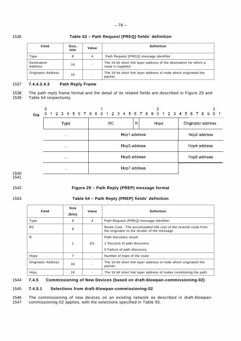
– 78 –
Table 53 – Path Request (PREQ) fields’ definition 1536
Field Size, bits Value Definition
Type 8 4 Path Request (PREQ) message identifier
Destination Address 16 -
The 16 bit short link layer address of the destination for which a route is supplied
Originator Address 16 - The 16 bit short link layer address of node which originated the packet.
7.4.4.2.4.3 Path Reply Frame 1537
The path reply frame format and the detail of its related fields are described in Figure 29 and 1538 Table 54 respectively. 1539
1540 1541
Figure 29 – Path Reply (PREP) message format 1542
Table 54 – Path Reply (PREP) fields’ definition 1543
Field Size
(bits) Value Definition
Type 8 4 Path Request (PREQ) message identifier
RC 8 Route Cost - The accumulated link cost of the reverse route from the originator to the sender of the message.
R
1 0/1
Path discovery result:
1 Success of path discovery
0 Failure of path discovery
Hops 7 - Number of hops of the route
Originator Address 16 - The 16 bit short link layer address of node which originated the packet.
HopN 16 - The 16 bit short link layer address of nodes constituting the path.
7.4.5 Commissioning of New Devices (based on draft- 6lowpan-commissioning-02) 1544
7.4.5.1 Selections from draft-6lowpan-commissioning -02 1545
The commissioning of new devices on an existing network as described in draft-6lowpan-1546 commissioning-02 applies, with the selections specified in Table 55. 1547
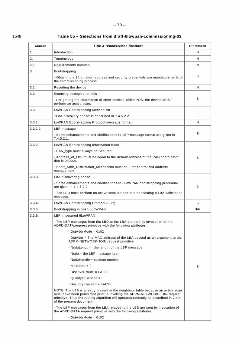
– 79 –
Table 55 – Selections from draft-6lowpan-commission ing-02 1548
Clause Title & remarks/modifications Statement
1. Introduction N
2. Terminology N
2.1. Requirements notation N
3. Bootstrapping
- Obtaining a 16-bit short address and security credentials are mandatory parts of the commissioning process.
S
3.1. Resetting the device N
3.2. Scanning through channels
- For getting the information of other devices within POS, the device MUST perform an active scan.
S
3.3. LoWPAN Bootstrapping Mechanism
-'LBA discovery phase' is described in 7.4.5.2.2 E
3.3.1. LoWPAN Bootstrapping Protocol message format N
3.3.1.1 LBP message
- Some enhancements and clarifications to LBP message format are given in 7.4.5.2.1.
E
3.3.2. LoWPAN Bootstrapping Information Base
- PAN_type must always be Secured
- Address_of_LBS must be equal to the default address of the PAN coordinator that is 0x0000.
- Short_Addr_Distribution_Mechanism must be 0 for centralized address management.
S
3.3.3. LBA discovering phase
- Some enhancements and clarifications to 6LoWPAN bootstrapping procedure are given in 7.4.5.2.2.
- The LBD must perform an active scan instead of broadcasting a LBA solicitation message.
E
3.3.4. LoWPAN Bootstrapping Protocol (LBP) S
3.3.5. Bootstrapping in open 6LoWPAN N/R
3.3.6. LBP in secured 6LoWPAN
- The LBP messages from the LBD to the LBA are sent by invocation of the ADPD-DATA.request primitive with the following attributes:
- DstAddrMode = 0x02
- DstAddr = The MAC address of the LBA passed as an argument to the ADPM-NETWORK-JOIN.request primitive
- NsduLength = the length of the LBP message
- Nsdu = the LBP message itself
- NsduHandle = random number
- MaxHops = 0
- DiscoverRoute = FALSE
- QualityOfService = 0
- SecurityEnabled = FALSE
NOTE The LBA is already present in the neighbour table because an active scan must have been performed prior to invoking the ADPM-NETWORK-JOIN.request primitive. Thus the routing algorithm will operates correctly as described in 7.4.4 of the present document.
- The LBP messages from the LBA relayed to the LBS are sent by invocation of the ADPD-DATA.request primitive with the following attributes:
- DstAddrMode = 0x02
S
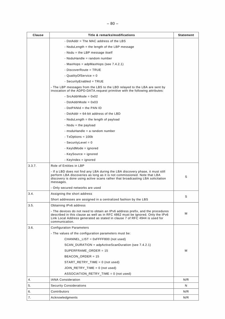
– 80 –
Clause Title & remarks/modifications Statement
- DstAddr = The MAC address of the LBS
- NsduLength = the length of the LBP message
- Nsdu = the LBP message itself
- NsduHandle = random number
- MaxHops = adpMaxHops (see 7.4.2.1)
- DiscoverRoute = TRUE
- QualityOfService = 0
- SecurityEnabled = TRUE
- The LBP messages from the LBS to the LBD relayed to the LBA are sent by invocation of the ADPD-DATA.request primitive with the following attributes:
- SrcAddrMode = 0x02
- DstAddrMode = 0x03
- DstPANId = the PAN ID
- DstAddr = 64-bit address of the LBD
- NsduLength = the length of payload
- Nsdu = the payload
- msduHandle = a random number
- TxOptions = 100b
- SecurityLevel = 0
- KeyIdMode = ignored
- KeySource = ignored
- KeyIndex = ignored
3.3.7. Role of Entities in LBP
- If a LBD does not find any LBA during the LBA discovery phase, it must still perform LBA discoveries as long as it is not commissioned. Note that LBA discovery is done using active scans rather that broadcasting LBA solicitation messages.
- Only secured networks are used
S
3.4. Assigning the short address
Short addresses are assigned in a centralized fashion by the LBS S
3.5. Obtaining IPv6 address
- The devices do not need to obtain an IPv6 address prefix, and the procedures described in this clause as well as in RFC 4862 must be ignored. Only the IPv6 Link Local Address generated as stated in clause 7 of RFC 4944 is used for communication.
M
3.6. Configuration Parameters
- The values of the configuration parameters must be:
CHANNEL_LIST = 0xFFFF800 (not used)
SCAN_DURATION = adpActiveScanDuration (see 7.4.2.1)
SUPERFRAME_ORDER = 15
BEACON_ORDER = 15
START_RETRY_TIME = 0 (not used)
JOIN_RETRY_TIME = 0 (not used)
ASSOCIATION_RETRY_TIME = 0 (not used)
M
4. IANA Consideration N/R
5. Security Considerations N
6. Contributors N/R
7. Acknowledgments N/R
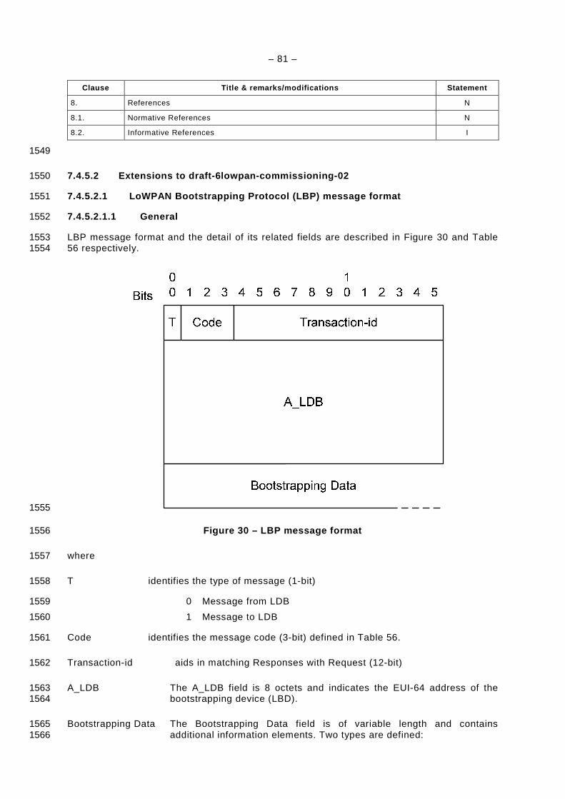
– 81 –
Clause Title & remarks/modifications Statement
8. References N
8.1. Normative References N
8.2. Informative References I
1549
7.4.5.2 Extensions to draft-6lowpan-commissioning-0 2 1550
7.4.5.2.1 LoWPAN Bootstrapping Protocol (LBP) messa ge format 1551
7.4.5.2.1.1 General 1552
LBP message format and the detail of its related fields are described in Figure 30 and Table 1553 56 respectively. 1554
1555
Figure 30 – LBP message format 1556
where 1557
T identifies the type of message (1-bit) 1558
0 Message from LDB 1559
1 Message to LDB 1560
Code identifies the message code (3-bit) defined in Table 56. 1561
Transaction-id aids in matching Responses with Request (12-bit) 1562
A_LDB The A_LDB field is 8 octets and indicates the EUI-64 address of the 1563 bootstrapping device (LBD). 1564
Bootstrapping Data The Bootstrapping Data field is of variable length and contains 1565 additional information elements. Two types are defined: 1566
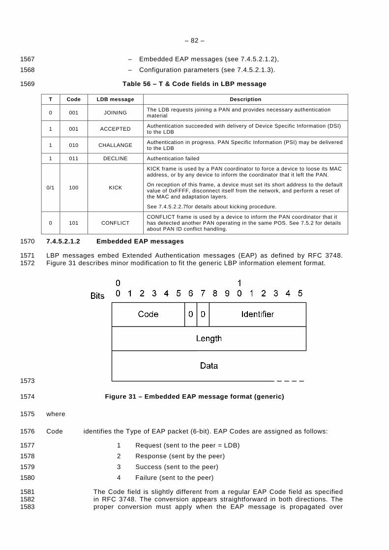
– 82 –
– Embedded EAP messages (see 7.4.5.2.1.2), 1567
– Configuration parameters (see 7.4.5.2.1.3). 1568
Table 56 – T & Code fields in LBP message 1569
T Code LDB message Description
0 001 JOINING The LDB requests joining a PAN and provides necessary authentication material
1 001 ACCEPTED Authentication succeeded with delivery of Device Specific Information (DSI) to the LDB
1 010 CHALLANGE Authentication in progress. PAN Specific Information (PSI) may be delivered to the LDB
1 011 DECLINE Authentication failed
0/1 100 KICK
KICK frame is used by a PAN coordinator to force a device to loose its MAC address, or by any device to inform the coordinator that it left the PAN.
On reception of this frame, a device must set its short address to the default value of 0xFFFF, disconnect itself from the network, and perform a reset of the MAC and adaptation layers.
See 7.4.5.2.2.7for details about kicking procedure.
0 101 CONFLICT CONFLICT frame is used by a device to inform the PAN coordinator that it has detected another PAN operating in the same POS. See 7.5.2 for details about PAN ID conflict handling.
7.4.5.2.1.2 Embedded EAP messages 1570
LBP messages embed Extended Authentication messages (EAP) as defined by RFC 3748. 1571 Figure 31 describes minor modification to fit the generic LBP information element format. 1572
1573
Figure 31 – Embedded EAP message format (generic) 1574
where 1575
Code identifies the Type of EAP packet (6-bit). EAP Codes are assigned as follows: 1576
1 Request (sent to the peer = LDB) 1577
2 Response (sent by the peer) 1578
3 Success (sent to the peer) 1579
4 Failure (sent to the peer) 1580
The Code field is slightly different from a regular EAP Code field as specified 1581 in RFC 3748. The conversion appears straightforward in both directions. The 1582 proper conversion must apply when the EAP message is propagated over 1583
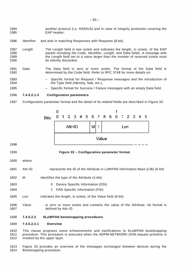
– 83 –
another protocol (i.e. RADIUS) and in case of integrity protection covering the 1584 EAP header. 1585
Identifier and aids in matching Responses with Requests (8-bit). 1586
Length The Length field is two octets and indicates the length, in octets, of the EAP 1587 packet including the Code, Identifier, Length, and Data fields. A message with 1588 the Length field set to a value larger than the number of received octets must 1589 be silently discarded. 1590
Data The Data field is zero or more octets. The format of the Data field is 1591 determined by the Code field. Refer to RFC 3748 for more details on: 1592
– Specific format for Request / Response messages and the introduction of 1593 the Type field (Identity, Nak, etc.), 1594
– Specific format for Success / Failure messages with an empty Data field. 1595
7.4.5.2.1.3 Configuration parameters 1596
Configuration parameter format and the detail of its related fields are described in Figure 32: 1597
1598
Figure 32 – Configuration parameter format 1599
where 1600
Attr-ID represents the ID of the Attribute in LoWPAN Information Base (LIB) (6-bit) 1601
M identifies the type of the Attribute (1-bit): 1602
0 Device Specific Information (DSI) 1603
1 PAN Specific Information (PSI) 1604
Len indicates the length, in octets, of the Value field (8-bit) 1605
Value is zero or more octets and contains the value of the Attribute. Its format is 1606 defined by Attr-ID. 1607
7.4.5.2.2 6LoWPAN bootstrapping procedures 1608
7.4.5.2.2.1 Overview 1609
This clause proposes some enhancements and clarifications to 6LoWPAN bootstrapping 1610 procedure. This procedure is executed when the ADPM-NETWORK-JOIN.request primitive is 1611 invoked by the upper layer. 1612
Figure 33 provides an overview of the messages exchanged between devices during the 1613 Bootstrapping procedure. 1614
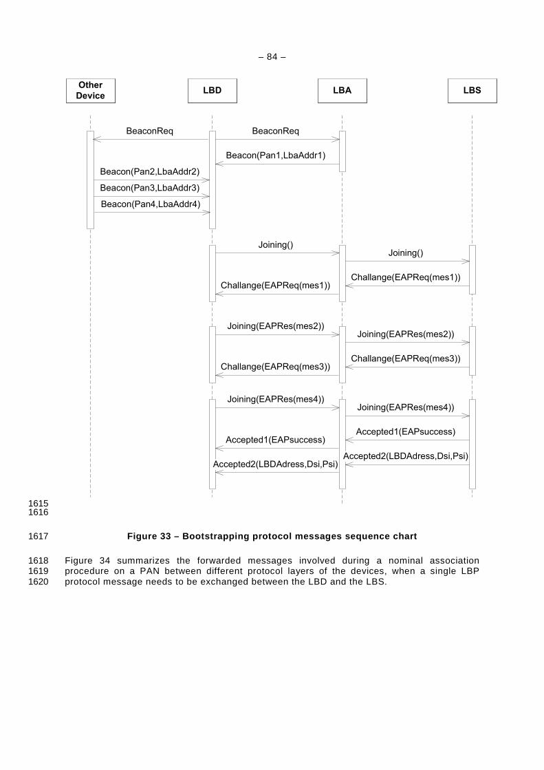
– 84 –
Other
DeviceLBSLBALBD
BeaconReq BeaconReq
Beacon(Pan1,LbaAddr1)
Beacon(Pan2,LbaAddr2)
Beacon(Pan3,LbaAddr3)
Beacon(Pan4,LbaAddr4)
Joining()Joining()
Challange(EAPReq(mes1))Challange(EAPReq(mes1))
Joining(EAPRes(mes2))Joining(EAPRes(mes2))
Challange(EAPReq(mes3))Challange(EAPReq(mes3))
Joining(EAPRes(mes4))Joining(EAPRes(mes4))
Accepted1(EAPsuccess)Accepted1(EAPsuccess)
Accepted2(LBDAdress,Dsi,Psi)Accepted2(LBDAdress,Dsi,Psi)
1615 1616
Figure 33 – Bootstrapping protocol messages sequenc e chart 1617
Figure 34 summarizes the forwarded messages involved during a nominal association 1618 procedure on a PAN between different protocol layers of the devices, when a single LBP 1619 protocol message needs to be exchanged between the LBD and the LBS. 1620
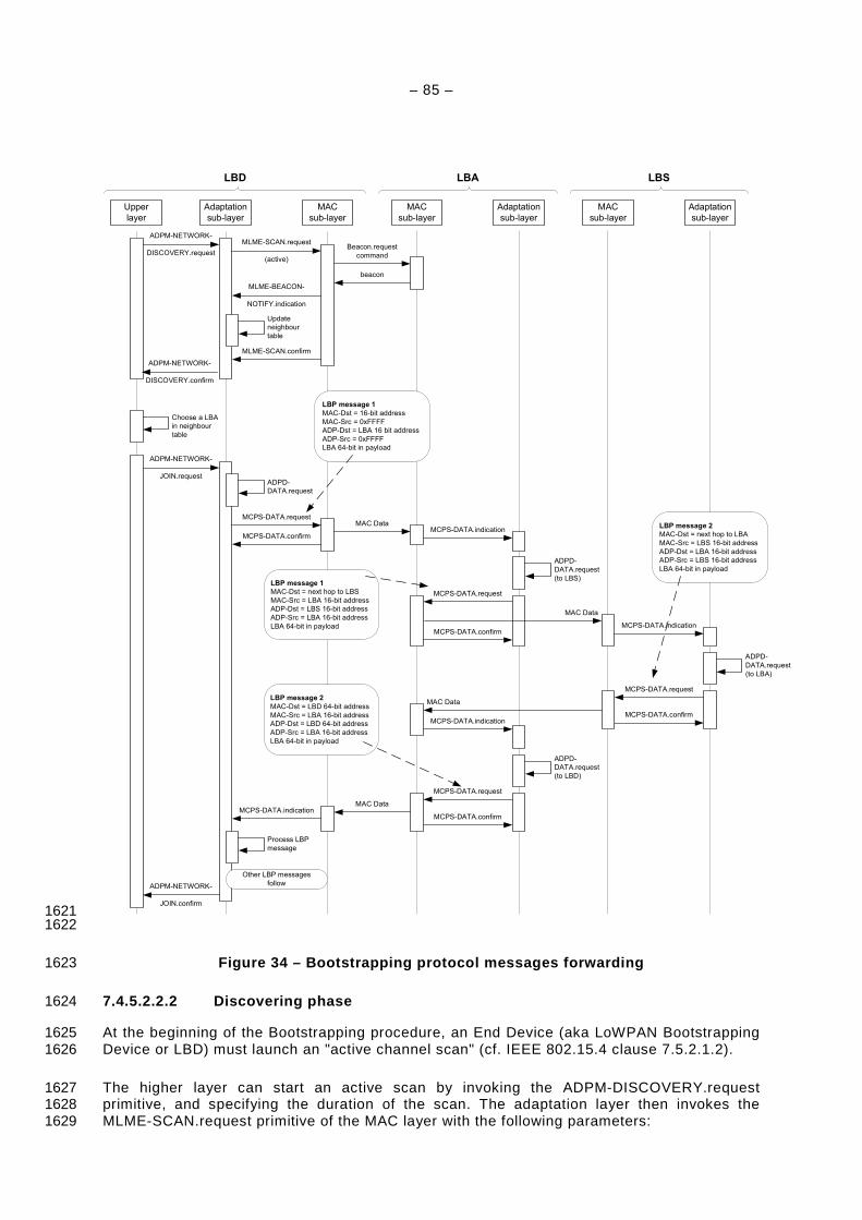
– 85 –
Upper
layer
Adaptation
sub-layer
MAC
sub-layer
MAC
sub-layer
ADPM-NETWORK-
DISCOVERY.request
Update
neighbour
table
ADPM-NETWORK-
DISCOVERY.confirm
MLME-SCAN.request
(active)
MLME-BEACON-
NOTIFY.indication
Beacon.request
command
Adaptation
sub-layer
MAC
sub-layer
MCPS-DATA.indication
MCPS-DATA.request
beacon
MLME-SCAN.confirm
LBD LBA
Choose a LBA
in neighbour
table
ADPM-NETWORK-
JOIN.requestADPD-
DATA.request
MCPS-DATA.request
MCPS-DATA.confirm
MAC Data
ADPD-
DATA.request
(to LBS)
MAC Data
MCPS-DATA.confirm
Adaptation
sub-layer
LBS
MCPS-DATA.indication
ADPD-
DATA.request
(to LBA)
MCPS-DATA.request
MCPS-DATA.confirm
MAC Data
MCPS-DATA.indication
ADPD-
DATA.request
(to LBD)
MCPS-DATA.request
MCPS-DATA.confirm
MAC DataMCPS-DATA.indication
Process LBP
message
ADPM-NETWORK-
JOIN.confirm
Other LBP messages
follow
LBP message 1
MAC-Dst = 16-bit address
MAC-Src = 0xFFFF
ADP-Dst = LBA 16 bit address
ADP-Src = 0xFFFF
LBA 64-bit in payload
LBP message 1
MAC-Dst = next hop to LBS
MAC-Src = LBA 16-bit address
ADP-Dst = LBS 16-bit address
ADP-Src = LBA 16-bit address
LBA 64-bit in payload
LBP message 2
MAC-Dst = next hop to LBA
MAC-Src = LBS 16-bit address
ADP-Dst = LBA 16-bit address
ADP-Src = LBS 16-bit address
LBA 64-bit in payload
LBP message 2
MAC-Dst = LBD 64-bit address
MAC-Src = LBA 16-bit address
ADP-Dst = LBD 64-bit address
ADP-Src = LBA 16-bit address
LBA 64-bit in payload
1621 1622
Figure 34 – Bootstrapping protocol messages forward ing 1623
7.4.5.2.2.2 Discovering phase 1624
At the beginning of the Bootstrapping procedure, an End Device (aka LoWPAN Bootstrapping 1625 Device or LBD) must launch an "active channel scan" (cf. IEEE 802.15.4 clause 7.5.2.1.2). 1626
The higher layer can start an active scan by invoking the ADPM-DISCOVERY.request 1627 primitive, and specifying the duration of the scan. The adaptation layer then invokes the 1628 MLME-SCAN.request primitive of the MAC layer with the following parameters: 1629
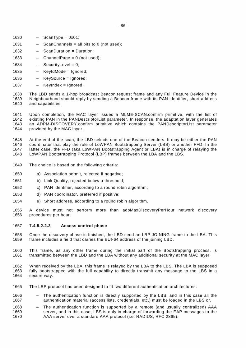
– 86 –
– ScanType = 0x01; 1630
– ScanChannels = all bits to 0 (not used); 1631
– ScanDuration = Duration; 1632
– ChannelPage = 0 (not used); 1633
– SecurityLevel = 0; 1634
– KeyIdMode = Ignored; 1635
– KeySource = Ignored; 1636
– KeyIndex = Ignored. 1637
The LBD sends a 1-hop broadcast Beacon.request frame and any Full Feature Device in the 1638 Neighbourhood should reply by sending a Beacon frame with its PAN identifier, short address 1639 and capabilities. 1640
Upon completion, the MAC layer issues a MLME-SCAN.confirm primitive, with the list of 1641 existing PAN in the PANDescriptorList parameter. In response, the adaptation layer generates 1642 an ADPM-DISCOVERY.confirm primitive which contains the PANDescriptorList parameter 1643 provided by the MAC layer. 1644
At the end of the scan, the LBD selects one of the Beacon senders. It may be either the PAN 1645 coordinator that play the role of LoWPAN Bootstrapping Server (LBS) or another FFD. In the 1646 latter case, the FFD (aka LoWPAN Bootstrapping Agent or LBA) is in charge of relaying the 1647 LoWPAN Bootstrapping Protocol (LBP) frames between the LBA and the LBS. 1648
The choice is based on the following criteria: 1649
a) Association permit, rejected if negative; 1650
b) Link Quality, rejected below a threshold; 1651
c) PAN identifier, according to a round robin algorithm; 1652
d) PAN coordinator, preferred if positive; 1653
e) Short address, according to a round robin algorithm. 1654
A device must not perform more than adpMaxDiscoveryPerHour network discovery 1655 procedures per hour. 1656
7.4.5.2.2.3 Access control phase 1657
Once the discovery phase is finished, the LBD send an LBP JOINING frame to the LBA. This 1658 frame includes a field that carries the EUI-64 address of the joining LBD. 1659
This frame, as any other frame during the initial part of the Bootstrapping process, is 1660 transmitted between the LBD and the LBA without any additional security at the MAC layer. 1661
When received by the LBA, this frame is relayed by the LBA to the LBS. The LBA is supposed 1662 fully bootstrapped with the full capability to directly transmit any message to the LBS in a 1663 secure way. 1664
The LBP protocol has been designed to fit two different authentication architectures: 1665
– The authentication function is directly supported by the LBS, and in this case all the 1666 authentication material (access lists, credentials, etc.) must be loaded in the LBS or, 1667
– The authentication function is supported by a remote (and usually centralized) AAA 1668 server, and in this case, LBS is only in charge of forwarding the EAP messages to the 1669 AAA server over a standard AAA protocol (i.e. RADIUS, RFC 2865). 1670
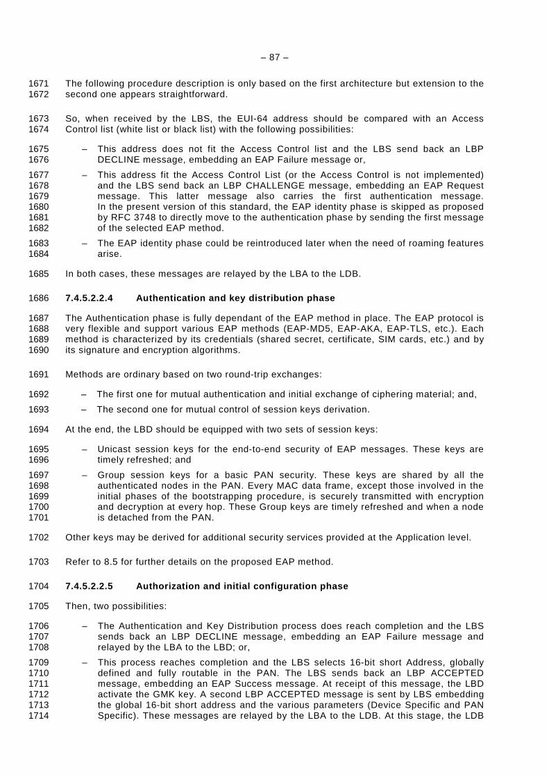
– 87 –
The following procedure description is only based on the first architecture but extension to the 1671 second one appears straightforward. 1672
So, when received by the LBS, the EUI-64 address should be compared with an Access 1673 Control list (white list or black list) with the following possibilities: 1674
– This address does not fit the Access Control list and the LBS send back an LBP 1675 DECLINE message, embedding an EAP Failure message or, 1676
– This address fit the Access Control List (or the Access Control is not implemented) 1677 and the LBS send back an LBP CHALLENGE message, embedding an EAP Request 1678 message. This latter message also carries the first authentication message. 1679 In the present version of this standard, the EAP identity phase is skipped as proposed 1680 by RFC 3748 to directly move to the authentication phase by sending the first message 1681 of the selected EAP method. 1682
– The EAP identity phase could be reintroduced later when the need of roaming features 1683 arise. 1684
In both cases, these messages are relayed by the LBA to the LDB. 1685
7.4.5.2.2.4 Authentication and key distribution pha se 1686
The Authentication phase is fully dependant of the EAP method in place. The EAP protocol is 1687 very flexible and support various EAP methods (EAP-MD5, EAP-AKA, EAP-TLS, etc.). Each 1688 method is characterized by its credentials (shared secret, certificate, SIM cards, etc.) and by 1689 its signature and encryption algorithms. 1690
Methods are ordinary based on two round-trip exchanges: 1691
– The first one for mutual authentication and initial exchange of ciphering material; and, 1692
– The second one for mutual control of session keys derivation. 1693
At the end, the LBD should be equipped with two sets of session keys: 1694
– Unicast session keys for the end-to-end security of EAP messages. These keys are 1695 timely refreshed; and 1696
– Group session keys for a basic PAN security. These keys are shared by all the 1697 authenticated nodes in the PAN. Every MAC data frame, except those involved in the 1698 initial phases of the bootstrapping procedure, is securely transmitted with encryption 1699 and decryption at every hop. These Group keys are timely refreshed and when a node 1700 is detached from the PAN. 1701
Other keys may be derived for additional security services provided at the Application level. 1702
Refer to 8.5 for further details on the proposed EAP method. 1703
7.4.5.2.2.5 Authorization and initial configuration phase 1704
Then, two possibilities: 1705
– The Authentication and Key Distribution process does reach completion and the LBS 1706 sends back an LBP DECLINE message, embedding an EAP Failure message and 1707 relayed by the LBA to the LBD; or, 1708
– This process reaches completion and the LBS selects 16-bit short Address, globally 1709 defined and fully routable in the PAN. The LBS sends back an LBP ACCEPTED 1710 message, embedding an EAP Success message. At receipt of this message, the LBD 1711 activate the GMK key. A second LBP ACCEPTED message is sent by LBS embedding 1712 the global 16-bit short address and the various parameters (Device Specific and PAN 1713 Specific). These messages are relayed by the LBA to the LDB. At this stage, the LDB 1714
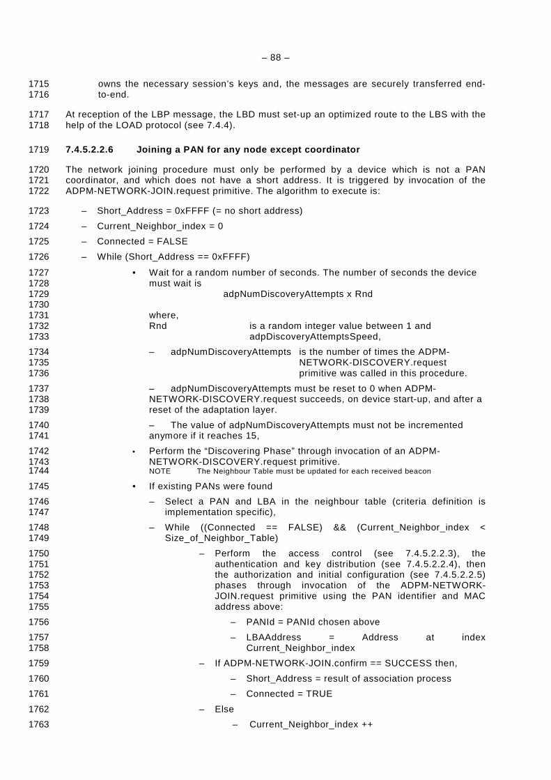
– 88 –
owns the necessary session’s keys and, the messages are securely transferred end-1715 to-end. 1716
At reception of the LBP message, the LBD must set-up an optimized route to the LBS with the 1717 help of the LOAD protocol (see 7.4.4). 1718
7.4.5.2.2.6 Joining a PAN for any node except coord inator 1719
The network joining procedure must only be performed by a device which is not a PAN 1720 coordinator, and which does not have a short address. It is triggered by invocation of the 1721 ADPM-NETWORK-JOIN.request primitive. The algorithm to execute is: 1722
– Short_Address = 0xFFFF (= no short address) 1723
– Current_Neighbor_index = 0 1724
– Connected = FALSE 1725
– While (Short_Address == 0xFFFF) 1726
• Wait for a random number of seconds. The number of seconds the device 1727 must wait is 1728 adpNumDiscoveryAttempts x Rnd 1729 1730 where, 1731 Rnd is a random integer value between 1 and 1732 adpDiscoveryAttemptsSpeed, 1733
– adpNumDiscoveryAttempts is the number of times the ADPM-1734 NETWORK-DISCOVERY.request 1735 primitive was called in this procedure. 1736
– adpNumDiscoveryAttempts must be reset to 0 when ADPM-1737 NETWORK-DISCOVERY.request succeeds, on device start-up, and after a 1738 reset of the adaptation layer. 1739
– The value of adpNumDiscoveryAttempts must not be incremented 1740 anymore if it reaches 15, 1741
• Perform the “Discovering Phase” through invocation of an ADPM-1742 NETWORK-DISCOVERY.request primitive. 1743 NOTE The Neighbour Table must be updated for each received beacon 1744
• If existing PANs were found 1745
– Select a PAN and LBA in the neighbour table (criteria definition is 1746 implementation specific), 1747
– While ((Connected == FALSE) && (Current_Neighbor_index < 1748 Size_of_Neighbor_Table) 1749
– Perform the access control (see 7.4.5.2.2.3), the 1750 authentication and key distribution (see 7.4.5.2.2.4), then 1751 the authorization and initial configuration (see 7.4.5.2.2.5) 1752 phases through invocation of the ADPM-NETWORK-1753 JOIN.request primitive using the PAN identifier and MAC 1754 address above: 1755
– PANId = PANId chosen above 1756
– LBAAddress = Address at index 1757 Current_Neighbor_index 1758
– If ADPM-NETWORK-JOIN.confirm == SUCCESS then, 1759
– Short_Address = result of association process 1760
– Connected = TRUE 1761
– Else 1762
– Current_Neighbor_index ++ 1763
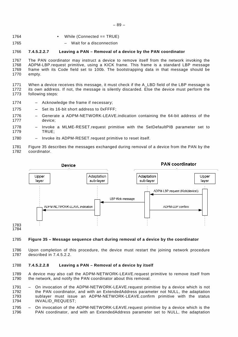
– 89 –
• While (Connected == TRUE) 1764
– Wait for a disconnection 1765
7.4.5.2.2.7 Leaving a PAN – Removal of a device by the PAN coordinator 1766
The PAN coordinator may instruct a device to remove itself from the network invoking the 1767 ADPM-LBP.request primitive, using a KICK frame. This frame is a standard LBP message 1768 frame with its Code field set to 100b. The bootstrapping data in that message should be 1769 empty. 1770
When a device receives this message, it must check if the A_LBD field of the LBP message is 1771 its own address. If not, the message is silently discarded. Else the device must perform the 1772 following steps: 1773
– Acknowledge the frame if necessary; 1774
– Set its 16-bit short address to 0xFFFF; 1775
– Generate a ADPM-NETWORK-LEAVE.indication containing the 64-bit address of the 1776 device; 1777
– Invoke a MLME-RESET.request primitive with the SetDefaultPIB parameter set to 1778 TRUE; 1779
– Invoke its ADPM-RESET.request primitive to reset itself. 1780
Figure 35 describes the messages exchanged during removal of a device from the PAN by the 1781 coordinator. 1782
1783 1784
Figure 35 – Message sequence chart during removal o f a device by the coordinator 1785
Upon completion of this procedure, the device must restart the joining network procedure 1786 described in 7.4.5.2.2. 1787
7.4.5.2.2.8 Leaving a PAN – Removal of a device by itself 1788
A device may also call the ADPM-NETWORK-LEAVE.request primitive to remove itself from 1789 the network, and notify the PAN coordinator about this removal. 1790
– On invocation of the ADPM-NETWORK-LEAVE.request primitive by a device which is not 1791 the PAN coordinator, and with an ExtendedAddress parameter not NULL, the adaptation 1792 sublayer must issue an ADPM-NETWORK-LEAVE.confirm primitive with the status 1793 INVALID_REQUEST; 1794
– On invocation of the ADPM-NETWORK-LEAVE.request primitive by a device which is the 1795 PAN coordinator, and with an ExtendedAddress parameter set to NULL, the adaptation 1796

– 90 –
sublayer must issue an ADPM-NETWORK-LEAVE.confirm primitive with the status 1797 INVALID_REQUEST. 1798
– On invocation of the ADPM-NETWORK-LEAVE.request primitive by a device which is not 1799 the PAN coordinator, and with a ExtendedAddress parameter set to NULL, the adaptation 1800 sublayer must: 1801
– Send a KICK frame to the PAN coordinator using a ADPD-DATA.request primitive 1802 (and setting the T field in the LBP message to 1, to indicate a message from LBD); 1803
– Set its 16-bit short address to 0xFFFF; 1804
– Generate a ADPM-NETWORK-LEAVE.indication containing the 64-bit address of 1805 the device; 1806
– Invoke a MLME-RESET.request primitive with the SetDefaultPIB parameter set to 1807 TRUE; 1808
– Invoke its ADPM-RESET.request primitive to reset itself. 1809
Figure 36 describes the messages exchanged during the removal of a device initiated by the 1810 device itself. 1811
1812 1813
Figure 36 – Message sequence chart during removal o f a device by itself 1814
On the PAN coordinator side, an ADPM-LBP.indication containing the KICK message received 1815 is generated to inform the upper layers. This message contains the 64-bit address of the 1816 device which removed itself from the PAN 1817
7.4.6 Fragment Recovery (based on draft-thubert-6lo wpan-simple-fragment-recovery-1818 02) 1819
The fragment recovery as described in draft-thubert-6lowpan-simple-fragment-recovery-02 1820 applies, with the selections specified in Table 57. 1821
Table 57 – Selections from draft-thubert-6lowpan-si mple-fragment-recovery-02 1822
Clause Title & remarks/modifications Statement
1. Introduction N
2. Terminology N
3. Rationale N
4. Requirements N
5. Overview N
6. New Dispatch types and headers N
– 91 –
Clause Title & remarks/modifications Statement
6.1. Recoverable Fragment Dispatch type and Header N
6.2. Fragment Acknowledgement Dispatch type and Header N
7. Outstanding Fragments Control N
8. Security Considerations N
9. IANA Considerations N
10. Acknowledgments N/R
11. References N
11.1. Normative References N
11.2. Informative References I
7.4.7 Spy Mode 1823
This mode is used to have a spy modem supervising all transmission on its behaviour. Once 1824 activated; the modem will process all packets like its own. The spy modem will generate an 1825 ADPD-DATA.indication for all packets received. It must also, behave like in normal mode; 1826 processing and forwarding packets. 1827
For example, on reception of an MCPS-DATA.indication which is not mine, the modem, in this 1828 case, will generate an ADPD-DATA.indication for upper layer then forward the packet toward 1829 the destination. 1830
The route cost of all links with a spy modem is set to 31 so we prevent routing a packet via 1831 such modem. 1832
If a spy modem receives a fragment, it will add an IPv6 fragment header to the packet so the 1833 upper layer can detect it. The fragment offset field will be set to the offset of the LOWPAN 1834 header and the Identification field to the Datagram_Tag. 1835
7.5 Functional description 1836
7.5.1 Network formation 1837
The network formation can only be performed by the PAN coordinator. Any device other than 1838 the PAN coordinator must not attempt to perform a network formation. 1839
Prior to the network formation, the PAN coordinator must perform an active scan as described 1840 in 7.4.5.2.2.2. If the PANDescriptorList given by the ADPM-DISCOVERY.confirm primitive is 1841 empty, then the PAN coordinator can start a new network. If the PANDescriptorList is not 1842 empty, the PAN coordinator should inform the rest of the system that a PAN is already 1843 operating in the POS of the device, and may start a new network afterwards. The procedures 1844 and decisions associated with this behaviour are implementation specific. 1845
After the network discovery, the PAN coordinator must set its PAN ID to the predefined value 1846 stored in it. This value can be obtained remotely from a configuration server, or locally 1847 computed. The way how this PAN ID is chosen and set in the coordinator is implementation 1848 specific. 1849
NOTE The PAN identifier must be logically ANDed with 0xFCFF, as described in 7.4.3 of the present document 1850 (clause 6 of RFC 4944). 1851
Once the PAN identifier has been determined, the adaptation sublayer must invoke the 1852 MLME-START.request with the following parameters: 1853
– PANId = the PAN identifier computed; 1854
– LogicalChannel = 0 (not used); 1855
– ChannelPage = 0 (not used); 1856
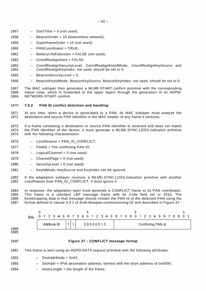
– 92 –
– StartTime = 0 (not used); 1857
– BeaconOrder = 15 (beaconless network); 1858
– SuperframeOrder = 15 (not used); 1859
– PANCoordinator = TRUE; 1860
– BatteryLifeExtension = FALSE (not used); 1861
– CoordRealignment = FALSE; 1862
– CoordRealignSecurityLevel, CoordRealignKeyIdMode, CoordRealignKeySource and 1863 CoordRealignKeyIndex: not used, should be set to 0; 1864
– BeaconSecurityLevel = 0; 1865
– BeaconKeyIdMode, BeaconKeySource, BeaconKeyIndex: not used, should be set to 0. 1866
The MAC sublayer then generates a MLME-START.confirm primitive with the corresponding 1867 status code, which is forwarded to the upper layers through the generation of an ADPM-1868 NETWORK-START.confirm. 1869
7.5.2 PAN ID conflict detection and handling 1870
At any time, when a device is associated to a PAN, its MAC sublayer must analyze the 1871 destination and source PAN Identifier in the MAC header of any frame it receives. 1872
If a frame containing a destination or source PAN Identifier is received and does not match 1873 the PAN Identifier of the device, it must generate a MLME-SYNC-LOSS.indication primitive 1874 with the following characteristics: 1875
– LossReason = PAN_ID_CONFLICT; 1876
– PANId = The conflicting PAN ID; 1877
– LogicalChannel = 0 (not used); 1878
– ChannelPage = 0 (not used); 1879
– SecurityLevel = 0 (not used); 1880
– KeyIdMode, KeySource and KeyIndex can be ignored. 1881
If the adaptation sublayer receives a MLME-SYNC-LOSS.indication primitive with another 1882 LossReason than PAN_ID_CONFLICT, it must ignore it. 1883
In response, the adaptation layer must generate a CONFLICT frame to its PAN coordinator. 1884 This frame is a standard LBP message frame with its Code field set to 101b. The 1885 bootstrapping data in that message should contain the PAN Id of the detected PAN using the 1886 format defined in clause 3.3.1 of draft-6lowpan-commissioning-02 and described in Figure 37: 1887
1888 1889
Figure 37 – CONFLICT message format 1890
This frame is sent using an ADPD-DATA.request primitive with the following attributes: 1891
– DstAddrMode = 0x02; 1892
– DstAddr = IPv6 destination address, formed with the short address of 0x0000; 1893
– NsduLength = the length of the frame; 1894
– 93 –
– Nsdu = the frame; 1895
– NsduHandle = a random number; 1896
– MaxHops = adpMaxHops; 1897
– DiscoverRoute = TRUE; 1898
– QualityOfService = FALSE; 1899
– SecurityEnabled = TRUE. 1900
A device must wait adpPANConflictWait seconds between two consecutive sending of a 1901 CONFLICT frame for the same conflicting PAN Id, and the total number of CONFLICT frames 1902 sent for a given conflicting PAN Id must not exceed adpMaxPANConflictCount. When this 1903 value is reached, the device must stop sending CONFLICT frames for this conflicting PAN Id. 1904
When the PAN coordinator receives this frame, it must generate an ADPM-NETWORK-1905 STATUS.indication primitive to the upper layer, with: 1906
– The Status field sets to PAN_ID_CONFLICT; and 1907
– The AdditionalInformation field sets to the conflicting PAN Id. 1908
8 Security 1909
8.1 Access control and authentication 1910
An End Device (ED) may not access to the network without a preliminary Identification (with 1911 comparison to white or black lists) and Authentication. Identification and Authentication are 1912 based on two parameters that personalized every ED: 1913
• A EUI-48 MAC address as defined in IEEE 802. This address may be easily converted into 1914 a EUI-64 as required by IEEE 802.15.4 and related documents; 1915
• A 128-bit shared secret (aka Pre-Shared Key or PSK) used as a credential during the 1916 authentication process. It is shared by the ED itself (aka peer) and an authentication 1917 server. The mutual authentication is based on a proof the other party knows the PSK. It is 1918 of highest importance, the PSK remains secret. 1919
The Identification and Authentication processes are activated when an ED restarts and may 1920 also be launched at any time according to the security policy in place. The related material is 1921 carried by the 6LoWPAN Bootstrapping Protocol (LBP) (see 7.4.5) that embeds the Extensible 1922 Authentication Protocol (EAP) (see 7.4.5.2.1.2). 1923
As shown in Figure 38, LBP and EAP have been designed to be relayed by intermediates 1924 nodes. Then during the Bootstrapping phase, when an ED (aka LBD) that have not yet 1925 acquired a routable 16-bit address, is a 1-hop distance of the PAN Coordinator (aka LBS) 1926 they can directly communicate. Otherwise, they must use an intermediate node (aka LBA) 1927 located at 1-hop distance of the LBD. 1928
Moreover, two different authentication architectures must be considered: 1929
– The authentication server function is directly supported by the LBS, and in this case all the 1930 authentication material (access lists, credentials, etc.) must be loaded in the LBS; 1931
– The authentication server function is supported by a remote (and usually centralized) AAA 1932 server, and in this case, the LBS is only in charge of forwarding the EAP messages to the 1933 AAA server over a standard AAA protocol (i.e. RADIUS RFC 2865). 1934

– 94 –
1935
Figure 38 – LBP and EAP Relaying Capabilities 1936
The Authentication process is fully dependant of the EAP method in place. The EAP protocol 1937 is very flexible and support various EAP methods (EAP-MD5, EAP-AKA, EAP-TLS, etc.). Each 1938 method is characterized by its credentials (shared secret, certificate, SIM cards, etc.) and by 1939 its signature and encryption algorithms. 1940
The method adopted for the OFDM CPL network is EAP-PSK (see 7.4.5), the main design 1941 goals of which are: 1942
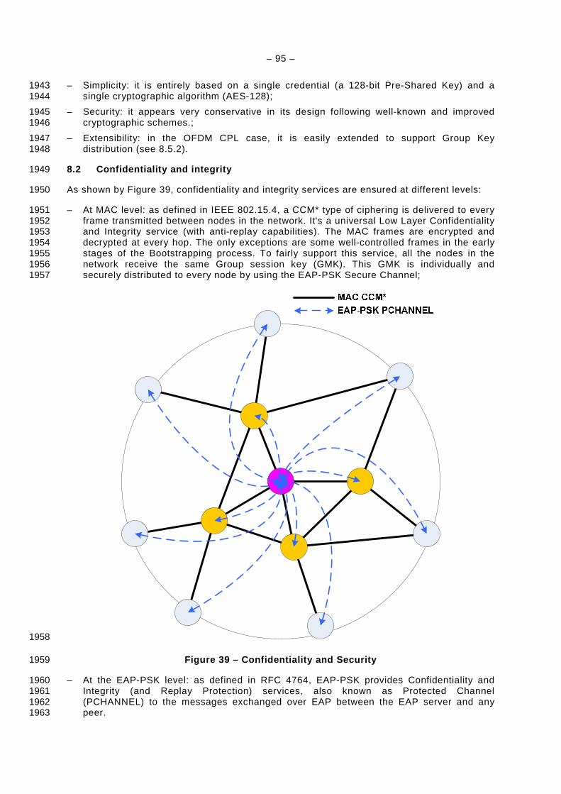
– 95 –
– Simplicity: it is entirely based on a single credential (a 128-bit Pre-Shared Key) and a 1943 single cryptographic algorithm (AES-128); 1944
– Security: it appears very conservative in its design following well-known and improved 1945 cryptographic schemes.; 1946
– Extensibility: in the OFDM CPL case, it is easily extended to support Group Key 1947 distribution (see 8.5.2). 1948
8.2 Confidentiality and integrity 1949
As shown by Figure 39, confidentiality and integrity services are ensured at different levels: 1950
– At MAC level: as defined in IEEE 802.15.4, a CCM* type of ciphering is delivered to every 1951 frame transmitted between nodes in the network. It's a universal Low Layer Confidentiality 1952 and Integrity service (with anti-replay capabilities). The MAC frames are encrypted and 1953 decrypted at every hop. The only exceptions are some well-controlled frames in the early 1954 stages of the Bootstrapping process. To fairly support this service, all the nodes in the 1955 network receive the same Group session key (GMK). This GMK is individually and 1956 securely distributed to every node by using the EAP-PSK Secure Channel; 1957
1958
Figure 39 – Confidentiality and Security 1959
– At the EAP-PSK level: as defined in RFC 4764, EAP-PSK provides Confidentiality and 1960 Integrity (and Replay Protection) services, also known as Protected Channel 1961 (PCHANNEL) to the messages exchanged over EAP between the EAP server and any 1962 peer. 1963
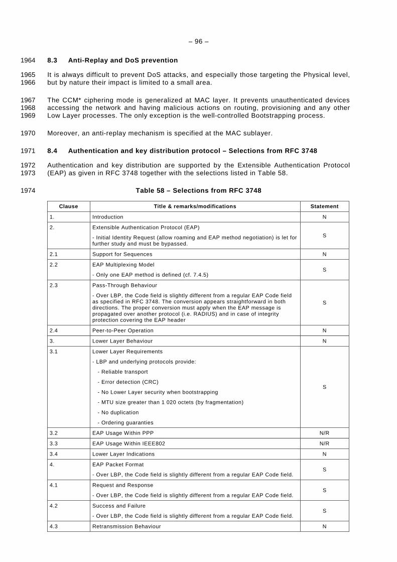
– 96 –
8.3 Anti-Replay and DoS prevention 1964
It is always difficult to prevent DoS attacks, and especially those targeting the Physical level, 1965 but by nature their impact is limited to a small area. 1966
The CCM* ciphering mode is generalized at MAC layer. It prevents unauthenticated devices 1967 accessing the network and having malicious actions on routing, provisioning and any other 1968 Low Layer processes. The only exception is the well-controlled Bootstrapping process. 1969
Moreover, an anti-replay mechanism is specified at the MAC sublayer. 1970
8.4 Authentication and key distribution protocol – Selections from RFC 3748 1971
Authentication and key distribution are supported by the Extensible Authentication Protocol 1972 (EAP) as given in RFC 3748 together with the selections listed in Table 58. 1973
Table 58 – Selections from RFC 3748 1974
Clause Title & remarks/modifications Statement
1. Introduction N
2. Extensible Authentication Protocol (EAP)
- Initial Identity Request (allow roaming and EAP method negotiation) is let for further study and must be bypassed.
S
2.1 Support for Sequences N
2.2 EAP Multiplexing Model
- Only one EAP method is defined (cf. 7.4.5) S
2.3 Pass-Through Behaviour
- Over LBP, the Code field is slightly different from a regular EAP Code field as specified in RFC 3748. The conversion appears straightforward in both directions. The proper conversion must apply when the EAP message is propagated over another protocol (i.e. RADIUS) and in case of integrity protection covering the EAP header
S
2.4 Peer-to-Peer Operation N
3. Lower Layer Behaviour N
3.1 Lower Layer Requirements
- LBP and underlying protocols provide:
- Reliable transport
- Error detection (CRC)
- No Lower Layer security when bootstrapping
- MTU size greater than 1 020 octets (by fragmentation)
- No duplication
- Ordering guaranties
S
3.2 EAP Usage Within PPP N/R
3.3 EAP Usage Within IEEE802 N/R
3.4 Lower Layer Indications N
4. EAP Packet Format
- Over LBP, the Code field is slightly different from a regular EAP Code field. S
4.1 Request and Response
- Over LBP, the Code field is slightly different from a regular EAP Code field. S
4.2 Success and Failure
- Over LBP, the Code field is slightly different from a regular EAP Code field. S
4.3 Retransmission Behaviour N
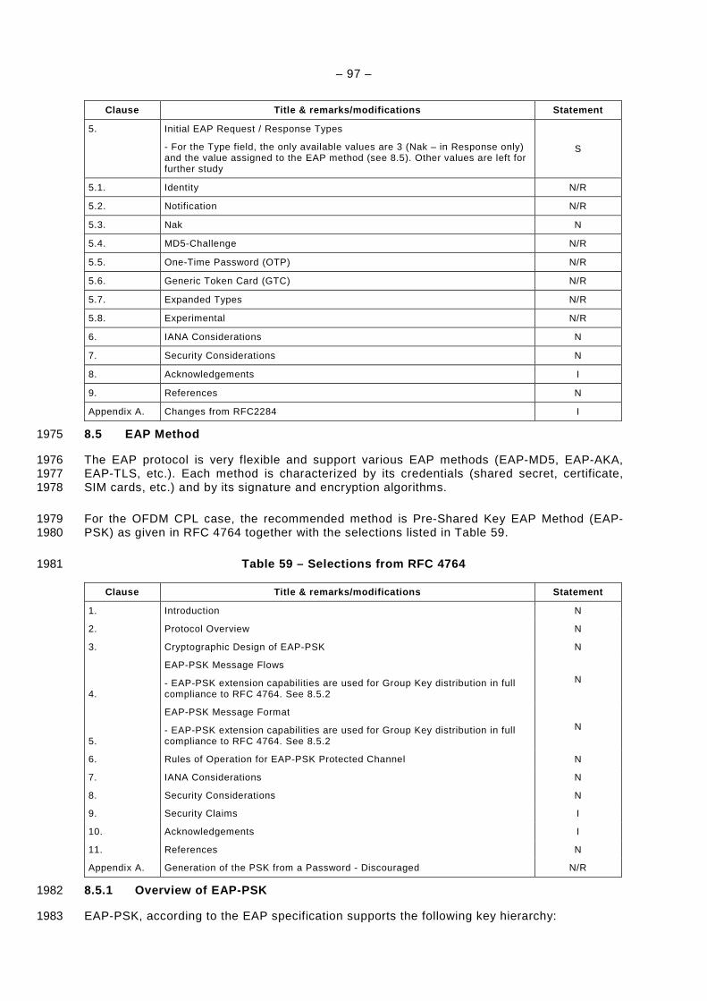
– 97 –
Clause Title & remarks/modifications Statement
5. Initial EAP Request / Response Types
- For the Type field, the only available values are 3 (Nak – in Response only) and the value assigned to the EAP method (see 8.5). Other values are left for further study
S
5.1. Identity N/R
5.2. Notification N/R
5.3. Nak N
5.4. MD5-Challenge N/R
5.5. One-Time Password (OTP) N/R
5.6. Generic Token Card (GTC) N/R
5.7. Expanded Types N/R
5.8. Experimental N/R
6. IANA Considerations N
7. Security Considerations N
8. Acknowledgements I
9. References N
Appendix A. Changes from RFC2284 I
8.5 EAP Method 1975
The EAP protocol is very flexible and support various EAP methods (EAP-MD5, EAP-AKA, 1976 EAP-TLS, etc.). Each method is characterized by its credentials (shared secret, certificate, 1977 SIM cards, etc.) and by its signature and encryption algorithms. 1978
For the OFDM CPL case, the recommended method is Pre-Shared Key EAP Method (EAP-1979 PSK) as given in RFC 4764 together with the selections listed in Table 59. 1980
Table 59 – Selections from RFC 4764 1981
Clause Title & remarks/modifications Statement
1. Introduction N
2. Protocol Overview N
3. Cryptographic Design of EAP-PSK N
4.
EAP-PSK Message Flows
- EAP-PSK extension capabilities are used for Group Key distribution in full compliance to RFC 4764. See 8.5.2
N
5.
EAP-PSK Message Format
- EAP-PSK extension capabilities are used for Group Key distribution in full compliance to RFC 4764. See 8.5.2
N
6. Rules of Operation for EAP-PSK Protected Channel N
7. IANA Considerations N
8. Security Considerations N
9. Security Claims I
10. Acknowledgements I
11. References N
Appendix A. Generation of the PSK from a Password - Discouraged N/R
8.5.1 Overview of EAP-PSK 1982
EAP-PSK, according to the EAP specification supports the following key hierarchy: 1983
– 98 –
Pre-Shared Key (PSK) PSK is the long-term 128-bit credential shared by the EAP 1984 server and the peer 1985
Authentication Key (AK) A 128-bit key derived from the PSK that the EAP peer and 1986 server use to mutually authenticate 1987
Key-Derivation Key (KDK) A 128-bit key derived from the PSK that the EAP peer and 1988 server use to derive session keys (such as TEK, MSK and 1989 EMSK) 1990
Transient EAP Key (TEK) A session key that is used to establish a protected channel 1991 between the EAP peer and server during the EAP 1992 authentication. EAP-PSK uses a 128-bit TEK in conjunction with 1993 AES-128 in EAX mode of operation as a cipher suite. 1994
Master Session Key (MSK) A session key derived between the EAP peer and server. EAP-1995 PSK generates a 512-bit MSK that may be used to provide 1996 security at the Application level. 1997
Extended Master Session Key (EMSK) A session key derived between the EAP peer and 1998 server. EAP-PSK generates a 512-bit EMSK. It is not used in 1999 OFDM CPL and must not be generated. 2000
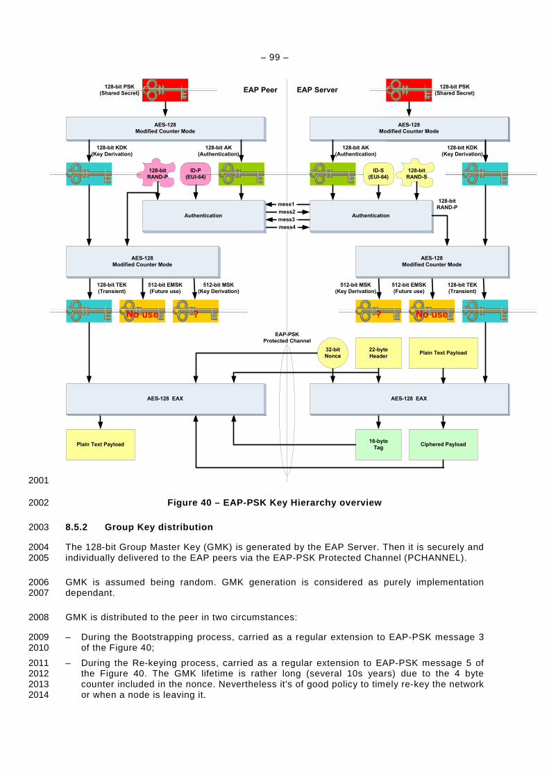
– 99 –
mess1 -
mess3 -
mess4 -
mess2 -
AES-128
Modified Counter Mode
128-bit PSK
(Shared Secret)
AES-128
Modified Counter Mode
128-bit KDK
(Key Derivation)
128-bit AK
(Authentication)
Authentication
ID-S
(EUI-64)
Authentication
ID-P
(EUI-64)
No use?
22-byte
HeaderPlain Text Payload
128-bit
RAND-S
128-bit
RAND-P
128-bit
RAND-P
Ciphered Payload16-byte
Tag
AES-128
Modified Counter Mode
128-bit AK
(Authentication)
128-bit KDK
(Key Derivation)
AES-128
Modified Counter Mode
?No use
AES-128
Modified Counter Mode
512-bit MSK
(Key Derivation)
512-bit EMSK
(Future use)
128-bit TEK
(Transient)
AES-128 EAX
512-bit MSK
(Key Derivation)
512-bit EMSK
(Future use)
128-bit TEK
(Transient)
128-bit PSK
(Shared Secret)
Plain Text Payload
AES-128 EAX
32-bit
Nonce
EAP Peer EAP Server
EAP-PSK
Protected Channel
2001
Figure 40 – EAP-PSK Key Hierarchy overview 2002
8.5.2 Group Key distribution 2003
The 128-bit Group Master Key (GMK) is generated by the EAP Server. Then it is securely and 2004 individually delivered to the EAP peers via the EAP-PSK Protected Channel (PCHANNEL). 2005
GMK is assumed being random. GMK generation is considered as purely implementation 2006 dependant. 2007
GMK is distributed to the peer in two circumstances: 2008
– During the Bootstrapping process, carried as a regular extension to EAP-PSK message 3 2009 of the Figure 40; 2010
– During the Re-keying process, carried as a regular extension to EAP-PSK message 5 of 2011 the Figure 40. The GMK lifetime is rather long (several 10s years) due to the 4 byte 2012 counter included in the nonce. Nevertheless it's of good policy to timely re-key the network 2013 or when a node is leaving it. 2014
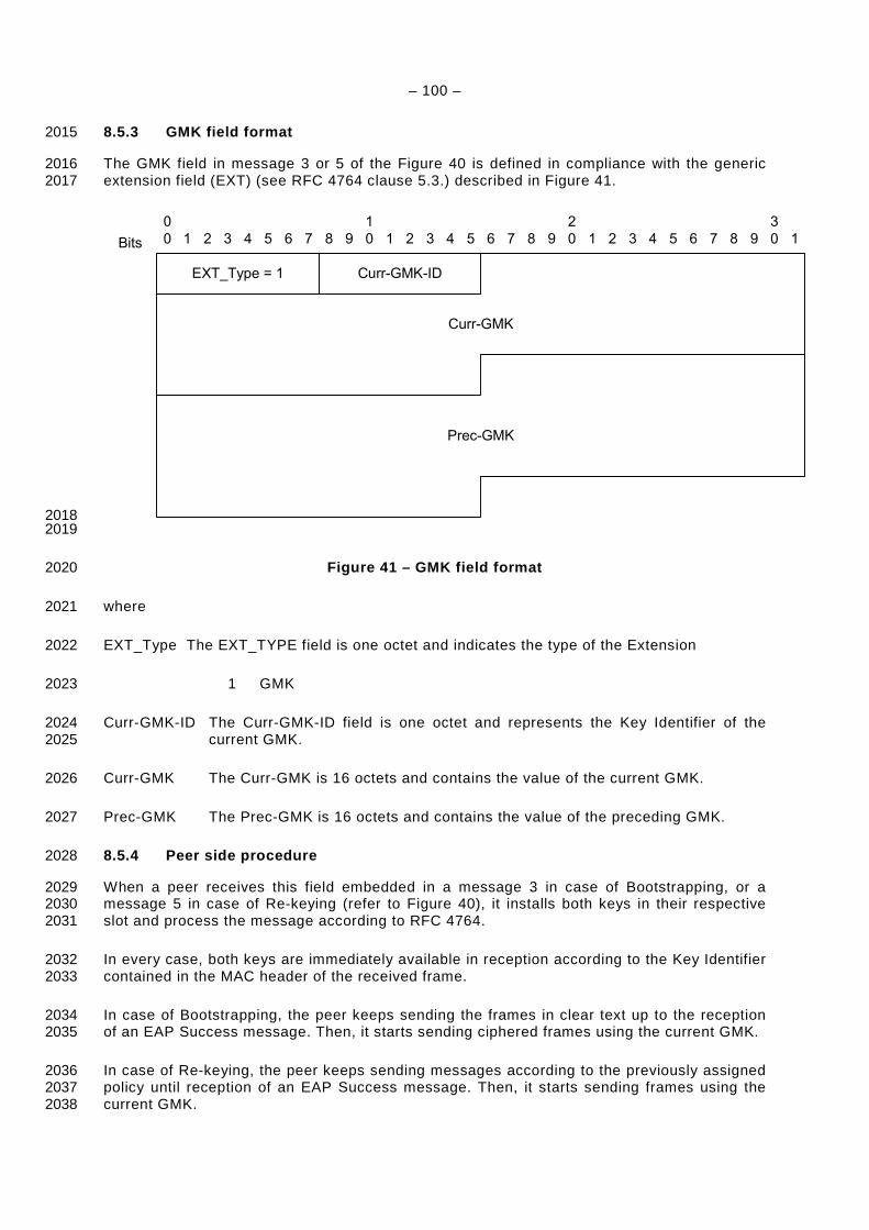
– 100 –
8.5.3 GMK field format 2015
The GMK field in message 3 or 5 of the Figure 40 is defined in compliance with the generic 2016 extension field (EXT) (see RFC 4764 clause 5.3.) described in Figure 41. 2017
0
0 54321
1
09876 54321 9876
2
0 54321Bits 9876
3
0 1
Curr-GMK-IDEXT_Type = 1
Curr-GMK
Prec-GMK
2018 2019
Figure 41 – GMK field format 2020
where 2021
EXT_Type The EXT_TYPE field is one octet and indicates the type of the Extension 2022
1 GMK 2023
Curr-GMK-ID The Curr-GMK-ID field is one octet and represents the Key Identifier of the 2024 current GMK. 2025
Curr-GMK The Curr-GMK is 16 octets and contains the value of the current GMK. 2026
Prec-GMK The Prec-GMK is 16 octets and contains the value of the preceding GMK. 2027
8.5.4 Peer side procedure 2028
When a peer receives this field embedded in a message 3 in case of Bootstrapping, or a 2029 message 5 in case of Re-keying (refer to Figure 40), it installs both keys in their respective 2030 slot and process the message according to RFC 4764. 2031
In every case, both keys are immediately available in reception according to the Key Identifier 2032 contained in the MAC header of the received frame. 2033
In case of Bootstrapping, the peer keeps sending the frames in clear text up to the reception 2034 of an EAP Success message. Then, it starts sending ciphered frames using the current GMK. 2035
In case of Re-keying, the peer keeps sending messages according to the previously assigned 2036 policy until reception of an EAP Success message. Then, it starts sending frames using the 2037 current GMK. 2038

– 101 –
After switching to the current GMK, a peer may keep receiving some messages encrypted 2039 with the preceding GMK during a transient period. The previous GMK must be deleted after a 2040 configurable delay (default value = 10 min). 2041
8.5.5 Server side procedure 2042
The Bootstrapping procedure is defined in 7.4.5.2.2. 2043
In case of re-keying, the EAP server generates a new GMK. Then it transmits a LBP 2044 challenge message, embedding an EAP Request message that contains the newly generated 2045 GMK, coupled with the preceding one, to every formerly authenticated peer. Upon reception 2046 of the corresponding EAP Response, or after a configurable delay (default value = 10 min), 2047 the server starts sending EAP Success messages for the validation of the new GMK. 2048

– 102 –
Annex A 2049 (normative) 2050
2051 Interleaver pattern generator 2052
The following piece of code is used for generating a good interleaving pattern. It needs two 2053 parameters, freqNum which is the number of data-holding sub-carriers, and symbNum which 2054 is the number of OFDM symbols. The interleaving table will be generated in ILV_TBL array. 2055
void Interleaver_init( int freqNum, int symbNum ) 2056
2057
volatile int i, j, I, J, m, n, m_i, m_j, n_i, n_j; 2058
n = symbNum; 2059
m = freqNum; 2060
n_j = 1; n_i = 1; 2061
m_i = 1; m_j = 1; 2062
2063
for ( i = 3; i < n; i++ ) 2064
if ( gcd(n,i) == 1 ) 2065
2066
n_j = i; 2067
break; 2068
2069
for ( i++; i < n; i++ ) 2070
if ( gcd(n,i) == 1 ) 2071
2072
n_i = i; 2073
break; 2074
2075
for ( i = 3; i < m; i++ ) 2076
if ( gcd(m,i) == 1 ) 2077
2078
m_i = i; 2079
break; 2080
2081
for ( i++; i < m; i++ ) 2082
if ( gcd(m,i) == 1 ) 2083
2084
m_j = i; 2085
break; 2086
2087
2088
ILV_SIZE = m * n 2089
2090
for ( j = 0; j < n; j++ ) 2091
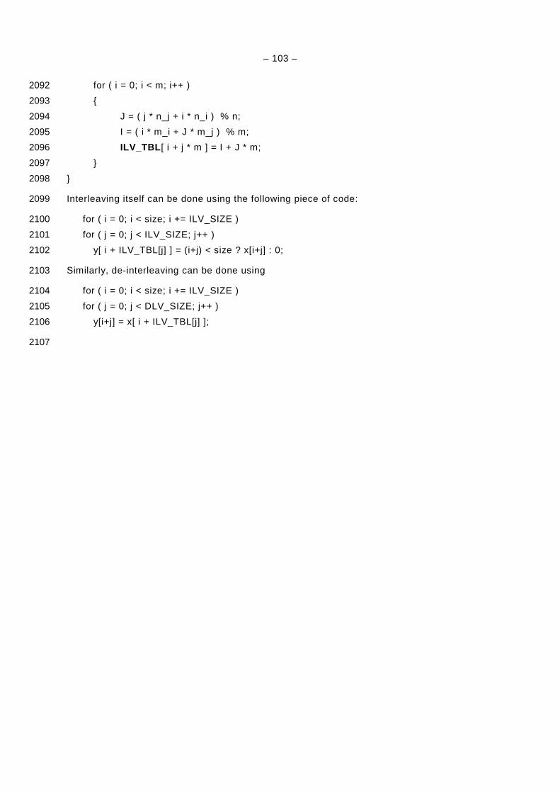
– 103 –
for ( i = 0; i < m; i++ ) 2092
2093
J = ( j * n_j + i * n_i ) % n; 2094
I = ( i * m_i + J * m_j ) % m; 2095
ILV_TBL [ i + j * m ] = I + J * m; 2096
2097
2098
Interleaving itself can be done using the following piece of code: 2099
for ( i = 0; i < size; i += ILV_SIZE ) 2100
for ( j = 0; j < ILV_SIZE; j++ ) 2101
y[ i + ILV_TBL[j] ] = (i+j) < size ? x[i+j] : 0; 2102
Similarly, de-interleaving can be done using 2103
for ( i = 0; i < size; i += ILV_SIZE ) 2104
for ( j = 0; j < DLV_SIZE; j++ ) 2105
y[i+j] = x[ i + ILV_TBL[j] ]; 2106
2107
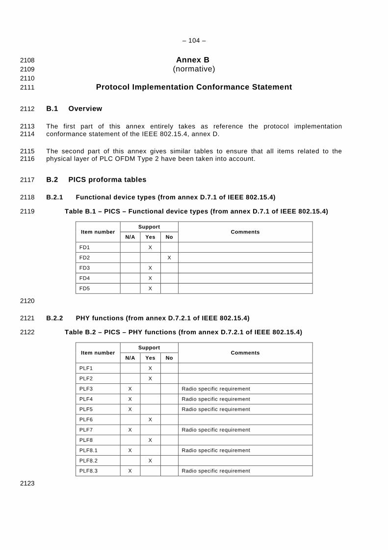
– 104 –
Annex B 2108 (normative) 2109
2110 Protocol Implementation Conformance Statement 2111
B.1 Overview 2112
The first part of this annex entirely takes as reference the protocol implementation 2113 conformance statement of the IEEE 802.15.4, annex D. 2114
The second part of this annex gives similar tables to ensure that all items related to the 2115 physical layer of PLC OFDM Type 2 have been taken into account. 2116
B.2 PICS proforma tables 2117
B.2.1 Functional device types (from annex D.7.1 of IEEE 802.15.4) 2118
Table B.1 – PICS – Functional device types (from an nex D.7.1 of IEEE 802.15.4) 2119
Item number Support
Comments N/A Yes No
FD1 X
FD2 X
FD3 X
FD4 X
FD5 X
2120
B.2.2 PHY functions (from annex D.7.2.1 of IEEE 802 .15.4) 2121
Table B.2 – PICS – PHY functions (from annex D.7.2. 1 of IEEE 802.15.4) 2122
Item number Support
Comments N/A Yes No
PLF1 X
PLF2 X
PLF3 X Radio specific requirement
PLF4 X Radio specific requirement
PLF5 X Radio specific requirement
PLF6 X
PLF7 X Radio specific requirement
PLF8 X
PLF8.1 X Radio specific requirement
PLF8.2 X
PLF8.3 X Radio specific requirement
2123
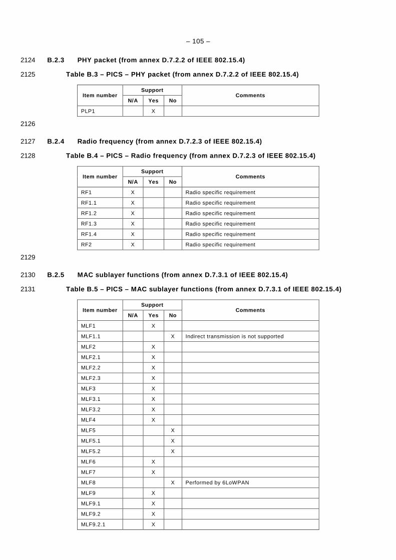
– 105 –
B.2.3 PHY packet (from annex D.7.2.2 of IEEE 802.15 .4) 2124
Table B.3 – PICS – PHY packet (from annex D.7.2.2 o f IEEE 802.15.4) 2125
Item number Support
Comments N/A Yes No
PLP1 X
2126
B.2.4 Radio frequency (from annex D.7.2.3 of IEEE 8 02.15.4) 2127
Table B.4 – PICS – Radio frequency (from annex D.7. 2.3 of IEEE 802.15.4) 2128
Item number Support
Comments N/A Yes No
RF1 X Radio specific requirement
RF1.1 X Radio specific requirement
RF1.2 X Radio specific requirement
RF1.3 X Radio specific requirement
RF1.4 X Radio specific requirement
RF2 X Radio specific requirement
2129
B.2.5 MAC sublayer functions (from annex D.7.3.1 of IEEE 802.15.4) 2130
Table B.5 – PICS – MAC sublayer functions (from ann ex D.7.3.1 of IEEE 802.15.4) 2131
Item number Support
Comments N/A Yes No
MLF1 X
MLF1.1 X Indirect transmission is not supported
MLF2 X
MLF2.1 X
MLF2.2 X
MLF2.3 X
MLF3 X
MLF3.1 X
MLF3.2 X
MLF4 X
MLF5 X
MLF5.1 X
MLF5.2 X
MLF6 X
MLF7 X
MLF8 X Performed by 6LoWPAN
MLF9 X
MLF9.1 X
MLF9.2 X
MLF9.2.1 X
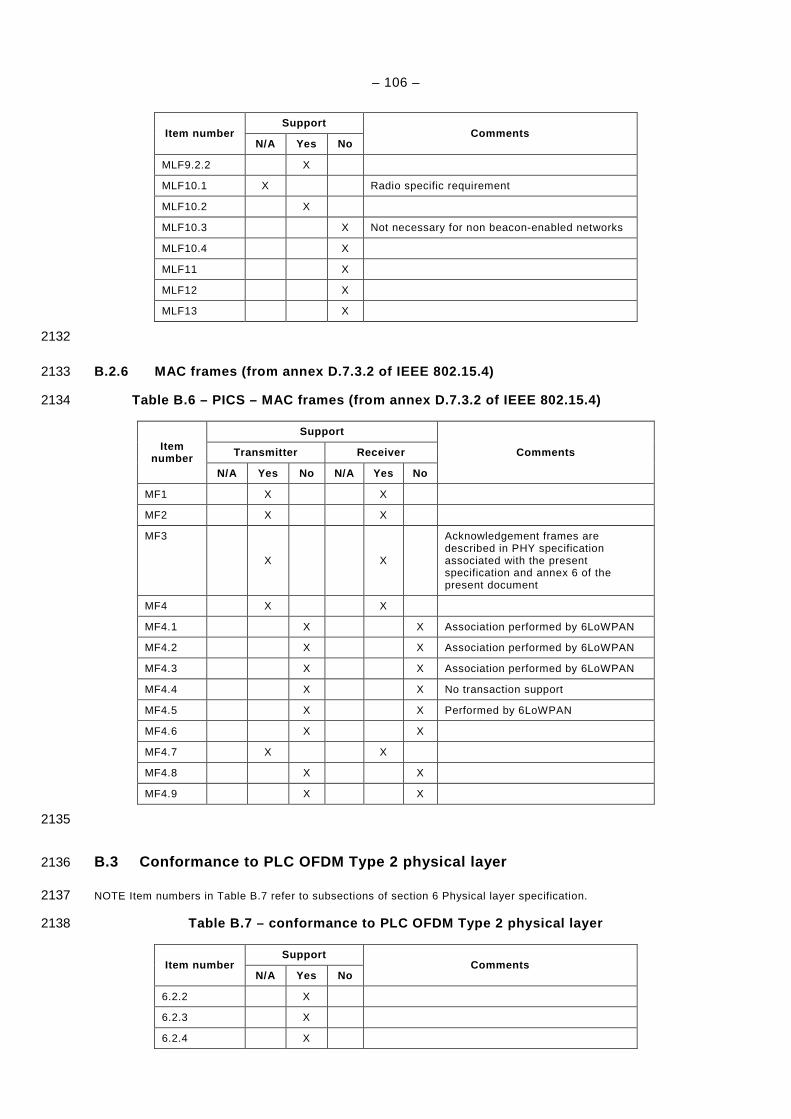
– 106 –
Item number Support
Comments N/A Yes No
MLF9.2.2 X
MLF10.1 X Radio specific requirement
MLF10.2 X
MLF10.3 X Not necessary for non beacon-enabled networks
MLF10.4 X
MLF11 X
MLF12 X
MLF13 X
2132
B.2.6 MAC frames (from annex D.7.3.2 of IEEE 802.15 .4) 2133
Table B.6 – PICS – MAC frames (from annex D.7.3.2 o f IEEE 802.15.4) 2134
Item number
Support
Comments Transmitter Receiver
N/A Yes No N/A Yes No
MF1 X X
MF2 X X
MF3
X X
Acknowledgement frames are described in PHY specification associated with the present specification and annex 6 of the present document
MF4 X X
MF4.1 X X Association performed by 6LoWPAN
MF4.2 X X Association performed by 6LoWPAN
MF4.3 X X Association performed by 6LoWPAN
MF4.4 X X No transaction support
MF4.5 X X Performed by 6LoWPAN
MF4.6 X X
MF4.7 X X
MF4.8 X X
MF4.9 X X
2135
B.3 Conformance to PLC OFDM Type 2 physical layer 2136
NOTE Item numbers in Table B.7 refer to subsections of section 6 Physical layer specification. 2137
Table B.7 – conformance to PLC OFDM Type 2 physical layer 2138
Item number Support
Comments N/A Yes No
6.2.2 X
6.2.3 X
6.2.4 X
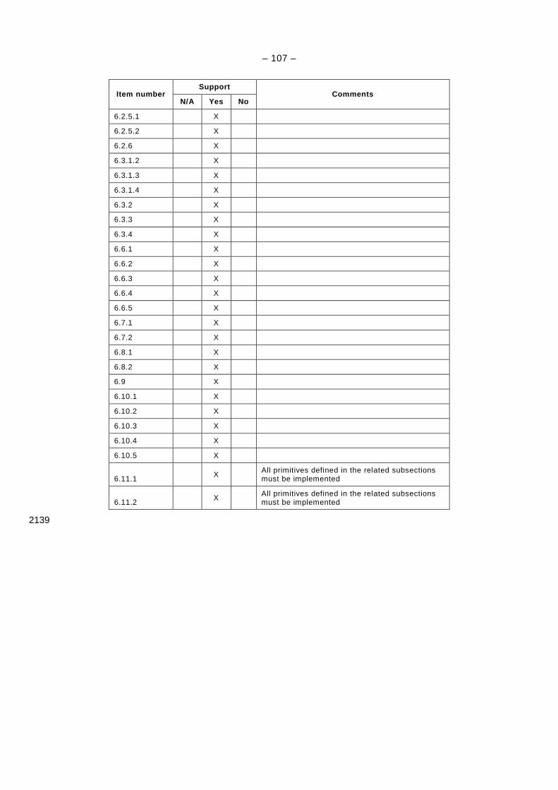
– 107 –
Item number Support
Comments N/A Yes No
6.2.5.1 X
6.2.5.2 X
6.2.6 X
6.3.1.2 X
6.3.1.3 X
6.3.1.4 X
6.3.2 X
6.3.3 X
6.3.4 X
6.6.1 X
6.6.2 X
6.6.3 X
6.6.4 X
6.6.5 X
6.7.1 X
6.7.2 X
6.8.1 X
6.8.2 X
6.9 X
6.10.1 X
6.10.2 X
6.10.3 X
6.10.4 X
6.10.5 X
6.11.1 X All primitives defined in the related subsections must be implemented
6.11.2 X All primitives defined in the related subsections
must be implemented
2139
– 108 –
Annex C 2140 (informative) 2141
2142 Routing Cost 2143
This part describes the characteristics a routing cost used in the LOAD routing algorithm 2144 (described in draft-daniel-6lowpan-load-adhoc-routing-03 and in 7.4.4) must have. 2145
A route cost is defined as the sum of all the link costs on the route. As described in draft-2146 daniel-6lowpan-load-adhoc-routing-03, a route cost is an integer value between 0 and 255, 2147 lower values meaning better routes. 2148
As there can be at most 8 hops on a route as defined in 7.4.3 (see clause 5.2 of RFC 4944), a 2149 link cost is an integer between 0 and 31. 2150
If we note P a route which goes through devices 110 ,...,, −NDDD , where N is the number 2151
of hops on the route ( 80 ≤< N ), and [ ] ji DDC , the link cost between devices iD and jD , 2152
the route cost ( )PRC of P can then be defined as: 2153
( ) [ ] ∑−
=+=
1
01,
N
iii DDCPRC 2154
The link cost should take into account PHY transmission parameters, number of hops, etc… 2155 The link cost computation algorithm is implementation dependant. 2156
– 109 –
Annex D 2157 (normative) 2158
2159 Channel access 2160
D.1 Overview 2161
The channel access is accomplished by using the Carrier Sense Multiple Access with 2162 Collision Avoidance (CSMA/CA) mechanism with a random backoff time. The random backoff 2163 mechanism spreads the time over which stations attempt to transmit, thereby reducing the 2164 probability of collision. Each time a device wishes to transmit data frames, it shall wait for a 2165 random period. If the channel is found to be idle, following the random backoff, the device 2166 shall transmit its data. If the channel is found to be busy, following the random backoff, the 2167 device shall wait for another random period before trying to access the channel again. 2168
A Carrier sense is a fundamental part of the distributed access procedure. Physical Carrier 2169 Sense (PCS) is provided by the PHY upon detection of the Preamble. In the latter case, PCS 2170 shall stay high long enough to be detected and Virtual Carrier Sense (VCS) to be asserted by 2171 the MAC. A virtual carrier sense mechanism is provided by the MAC by tracking the expected 2172 duration of channel occupancy. Virtual carrier sense is set by the length of received packet or 2173 upon collision. In these cases, virtual carrier sense tracks the expected duration of the Busy 2174 state of the medium. The medium shall also be considered Busy when the station is 2175 transmitting. 2176
A VCS timer is maintained by all stations to improve reliability of channel access. The VCS 2177 timer is set based on received long (data) or short (ACK) frames. The VCS timer is also set 2178 upon collision or when the station powers up. Stations use this information to compute the 2179 expected Busy condition of the medium or the expected duration of the Contention State and 2180 store this information in the VCS timer. 2181
A Collision occurs in each of the following circumstances: 2182
– The transmitting station receives a something other than ACK or NACK response when a 2183 response is expected. 2184
– The transmitting station shall infer a Collision from the absence of any response to a 2185 transmission when a response is expected. Note that the absence of a response could 2186 also be the result of a bad channel. Since there is no way to distinguish between the two 2187 causes a Collision is inferred. 2188
D.2 Interframe (IFS) Spacing 2189
A time intervals between frames on the medium constitute the Interframe Space and are 2190 necessary due to propagation and processing time. As shown in Figure D.1, three interframe 2191 space values are defined. Contention Interframe Space (CIFS) occurs after the end of the 2192 previous transmission. The second defined interval is the Response Interframe Space (RIFS). 2193
RIFS is the time between the end of a transmission and the start of its associated response. If 2194 no response is expected, the CIFS is in effect. 2195
An Extended Interframe Space (EIFS) is defined for conditions when the station does not 2196 have complete knowledge of the state of the medium. This can occur when the station initially 2197 attaches to the network, when errors in the received frames make them impossible to decode 2198 unambiguously. If a packet is received and correctly decoded before the expiration of the 2199 EIFS, then the EIFS is cancelled. The EIFS is significantly longer than the other interframe 2200 spaces, providing protection from Collision for an ongoing frame transmission or segment 2201 burst when any of these conditions occur. The EIFS is calculated as follows: 2202
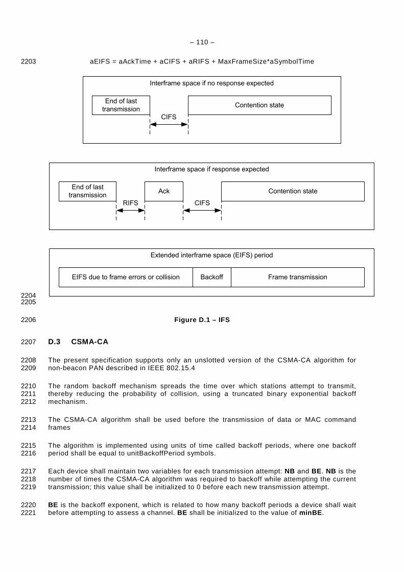
– 110 –
aEIFS = aAckTime + aCIFS + aRIFS + MaxFrameSize*aSymbolTime 2203
Interframe space if no response expected
End of last
transmissionContention state
CIFS
Interframe space if response expected
End of last
transmissionContention state
CIFS
Ack
RIFS
Extended interframe space (EIFS) period
EIFS due to frame errors or collision Frame transmissionBackoff
2204 2205
Figure D.1 – IFS 2206
D.3 CSMA-CA 2207
The present specification supports only an unslotted version of the CSMA-CA algorithm for 2208 non-beacon PAN described in IEEE 802.15.4 2209
The random backoff mechanism spreads the time over which stations attempt to transmit, 2210 thereby reducing the probability of collision, using a truncated binary exponential backoff 2211 mechanism. 2212
The CSMA-CA algorithm shall be used before the transmission of data or MAC command 2213 frames 2214
The algorithm is implemented using units of time called backoff periods, where one backoff 2215 period shall be equal to unitBackoffPeriod symbols. 2216
Each device shall maintain two variables for each transmission attempt: NB and BE. NB is the 2217 number of times the CSMA-CA algorithm was required to backoff while attempting the current 2218 transmission; this value shall be initialized to 0 before each new transmission attempt. 2219
BE is the backoff exponent, which is related to how many backoff periods a device shall wait 2220 before attempting to assess a channel. BE shall be initialized to the value of minBE. 2221
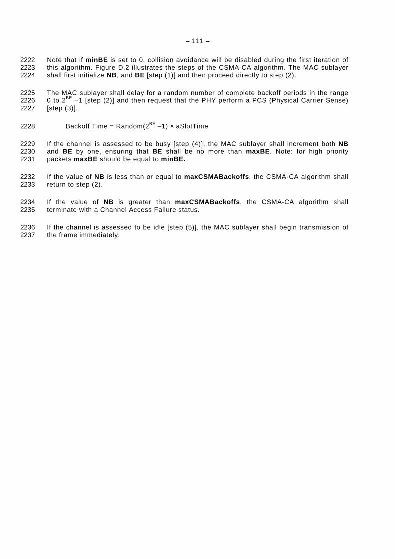
– 111 –
Note that if minBE is set to 0, collision avoidance will be disabled during the first iteration of 2222 this algorithm. Figure D.2 illustrates the steps of the CSMA-CA algorithm. The MAC sublayer 2223 shall first initialize NB, and BE [step (1)] and then proceed directly to step (2). 2224
The MAC sublayer shall delay for a random number of complete backoff periods in the range 2225 0 to 2BE –1 [step (2)] and then request that the PHY perform a PCS (Physical Carrier Sense) 2226 [step (3)]. 2227
Backoff Time = Random(2BE –1) × aSlotTime 2228
If the channel is assessed to be busy [step (4)], the MAC sublayer shall increment both NB 2229 and BE by one, ensuring that BE shall be no more than maxBE. Note: for high priority 2230 packets maxBE should be equal to minBE. 2231
If the value of NB is less than or equal to maxCSMABackoffs , the CSMA-CA algorithm shall 2232 return to step (2). 2233
If the value of NB is greater than maxCSMABackoffs , the CSMA-CA algorithm shall 2234 terminate with a Channel Access Failure status. 2235
If the channel is assessed to be idle [step (5)], the MAC sublayer shall begin transmission of 2236 the frame immediately. 2237

– 112 –
FAILURE
NB=0BE = minBE
CSMA/CA
Perform PCS
SUCCESS
Channel idle?
Delay forrandom(2BE - 1) unit
backoff periods
NO YES
NB++BE = min(BE++, maxBE)
NB >maxCSMABackoffs?
YESNO
(1)
(2)
(3)
(5)(4)
2238
Figure D.2 – CSMA/CA algorithm 2239
D.4 Priority 2240
Prioritized access to the channel can be beneficial for real time application or control 2241 application when urgent message should be delivered as soon as possible. Only two levels of 2242 priority (High and Normal) will be used to minimize complexity. Priority resolution is 2243 implemented by using two contention time windows during contention state as shown in 2244 Figure D.3: 2245
2246 2247
Figure D.3 – Priority Contention Windows 2248

– 113 –
First slot of contention window is called Contention Free Slot (CFS). It is used to implement 2249 packet bursting without backoff procedure in order to prevent possible interruption from other 2250 nodes. 2251
The high and normal priority stations will compete for channel during HPCW and NPCW 2252 correspondingly. Since HPCW is located before NPCW high priority stations will get access to 2253 the channel before station with normal priority. Duration of HPCW and NPCW are calculated 2254 as follow: 2255
HPCW time = macHighPrioirtyWindowSize * aSlotTime; 2256
NPCW time = (2maxBE * aSlotTime) - HPCW time; 2257
CFS time = aSlotTime; 2258
D.5 ARQ 2259
ARQ (Automatic Repeat reQuest) is implemented based on acknowledged and 2260 unacknowledged retransmission. The MAC sublayer uses a response type as part of its ARQ 2261 mechanism. ACK is a traditional positive acknowledgment that when received allows the 2262 transmitter to assume successful delivery of the frame. The negative acknowledgment (NACK) 2263 is used to inform a packet originator that the receiver received the packet but it was 2264 corrupted. 2265
A successful reception and validation of a data can be confirmed with an acknowledgment. If 2266 the receiving device is unable to handle the received data frame for any reason, the message 2267 is not acknowledged. 2268
If the originator does not receive an acknowledgment after waiting period, it assumes that the 2269 transmission was unsuccessful and retries the frame transmission. If an acknowledgment is 2270 still not received after several retries, the originator can choose either to terminate the 2271 transaction or to try again. When the acknowledgment is not required, the originator assumes 2272 the transmission was successful. Also if acknowledgment is not required, the originator can 2273 retransmit the same packets few times to increase probability of data delivery. The receiver 2274 should be able distinguish and discard redundant copies using the Sequence Number and 2275 Segment Count. The retransmitted packet will have the same Sequence Number and 2276 Segment Count as original. 2277
The acknowledgment cannot be requested for broadcast or multicast transmission. On 2278 transmit side ARQ requires configurable number of retransmissions (cf. macMaxFrameRetries 2279 from 7.4.2 of IEEE 802.15.4) as shown in Figure D.4. 2280
On receive side ARQ generates acknowledgement for PLC packet with correct FCS (CRC16) 2281 if packet corresponds to this address as shown in Figure D.5. 2282
The received packet FCS (16 bit) will be sent back to the packet originator as a part of an 2283 acknowledgement (Frame Control Header). 2284
All nodes will detect ACK during response time but only one station expecting ACK will accept 2285 it as acknowledgement and use 16 bit of FCS from ACK for identification. 2286
MAC acknowledgement is described in details in 7.3.2. 2287
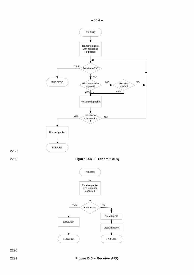
– 114 –
Transmit packetwith response
expected
TX ARQ
Response time expired?
Retransmit packet
FAILURE
SUCCESS
Receive ACK?
Number of retries expired
?
Discard packet
NO
YES
YES
NO
YES NO
Receive NACK?
NO
YES
2288
Figure D.4 – Transmit ARQ 2289
Receive packetwith response
expected
RX ARQ
Discard packet
SUCCESS FAILURE
Valid FCS?
Send ACK
NOYES
Send NACK
2290
Figure D.5 – Receive ARQ 2291
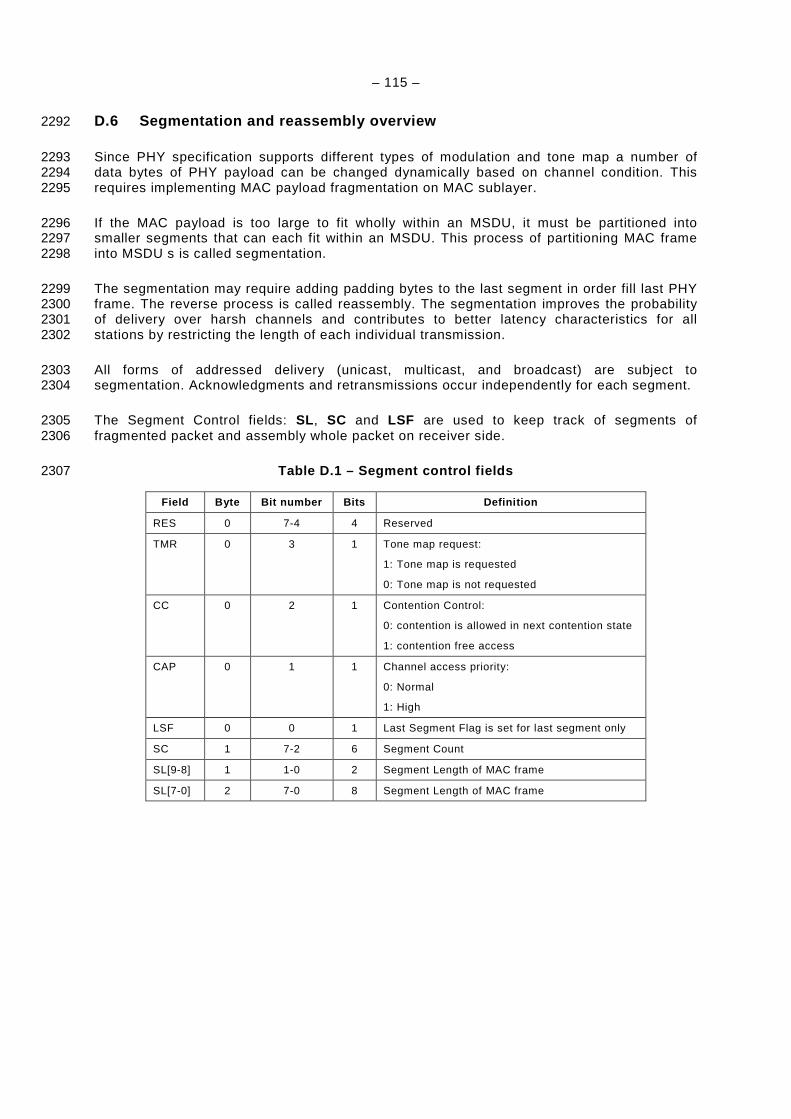
– 115 –
D.6 Segmentation and reassembly overview 2292
Since PHY specification supports different types of modulation and tone map a number of 2293 data bytes of PHY payload can be changed dynamically based on channel condition. This 2294 requires implementing MAC payload fragmentation on MAC sublayer. 2295
If the MAC payload is too large to fit wholly within an MSDU, it must be partitioned into 2296 smaller segments that can each fit within an MSDU. This process of partitioning MAC frame 2297 into MSDU s is called segmentation. 2298
The segmentation may require adding padding bytes to the last segment in order fill last PHY 2299 frame. The reverse process is called reassembly. The segmentation improves the probability 2300 of delivery over harsh channels and contributes to better latency characteristics for all 2301 stations by restricting the length of each individual transmission. 2302
All forms of addressed delivery (unicast, multicast, and broadcast) are subject to 2303 segmentation. Acknowledgments and retransmissions occur independently for each segment. 2304
The Segment Control fields: SL , SC and LSF are used to keep track of segments of 2305 fragmented packet and assembly whole packet on receiver side. 2306
Table D.1 – Segment control fields 2307
Field Byte Bit number Bits Definition
RES 0 7-4 4 Reserved
TMR 0 3 1 Tone map request:
1: Tone map is requested
0: Tone map is not requested
CC 0 2 1 Contention Control:
0: contention is allowed in next contention state
1: contention free access
CAP 0 1 1 Channel access priority:
0: Normal
1: High
LSF 0 0 1 Last Segment Flag is set for last segment only
SC 1 7-2 6 Segment Count
SL[9-8] 1 1-0 2 Segment Length of MAC frame
SL[7-0] 2 7-0 8 Segment Length of MAC frame

– 116 –
Annex E 2308 (normative) 2309
2310 Modified MAC sublayer data primitives 2311
E.1 MCPS-DATA.request 2312
The semantic of the MCPS-DATA.request primitive is as follows: 2313
MCPS-DATA.request ( 2314
SrcAddrMode, 2315
DstAddrMode, 2316
DstPANId, 2317
DstAddr, 2318
msduLength, 2319
msdu, 2320
msduHandle, 2321
TxOptions, 2322
SecurityLevel, 2323
KeyIdMode, 2324
KeySource, 2325
KeyIndex, 2326
QualityOfService 2327
) 2328
Table E.1 specifies the parameters for the MCPS-DATA.request primitive. 2329
Table E.1 – MCPS-DATA.request parameters 2330
Name Type Valid range Description
SrcAddrMode Integer 0x00–0x03 The source addressing mode for this primitive and subsequent MPDU.
This value can take one of the following values:
0x00 = no address (addressing fields omitted, see 7.2.1.1.8).
0x01 = reserved.
0x02 = 16-bit short address.
0x03 = 64-bit extended address.
DstAddrMode Integer 0x00–0x03 The destination addressing mode for this primitive and subsequent MPDU.
This value can take one of the following values:
0x00 = no address (addressing fields omitted, see 7.2.1.1.6).
0x01 = reserved.
0x02 = 16-bit short address.
0x03 = 64-bit extended address.
DstPANId Integer 0x0000–0xffff The 16-bit PAN identifier of the entity to which the MSDU is being transferred.

– 117 –
Name Type Valid range Description
DstAddr Device address As specified by
the DstAddrMode
parameter
The individual device address of the entity to which the MSDU is being transferred.
msduLength Integer aMaxMACPayloadSize The number of octets contained in the MSDU to be transmitted by the MAC sublayer entity.
msdu Set of octets — The set of octets forming the MSDU to be transmitted by the MAC sublayer entity.
msduHandle Integer 0x00–0xff The handle associated with the MSDU to be transmitted by the MAC sublayer entity.
TxOptions Bitmap 3-bit field The 3 bits (b0 , b1 , b2 ) indicate the transmission options for this MSDU.
For b0:
1 = acknowledged transmission,
0 = unacknowledged transmission.
For b1:
1 = GTS transmission,
0 = CAP transmission for a beacon-enabled PAN.
For b2:
1 = indirect transmission,
0 = direct transmission.
For a non beacon-enabled PAN, bit b1 should always be set to 0.
QualityOfService Integer 0x00–0x02 The QOS (Quality of Service) parameter of the MSDU to be transmitted by the MAC sublayer entity.
This value can take one of the following values:
0 = Normal priority,
1 = High priority,
2 = Contention free.
SecurityLevel Integer 0x00–0x07 The security level to be used (see 7.3.6).
KeyIdMode Integer 0x00–0x03 The mode used to identify the key to be used (see 7.3.6).This parameter is ignored if the SecurityLevel parameter is set to 0x00.
KeySource Set of 0,
4, or 8octets
As specified by
the KeyIdMode
parameter
The originator of the key to be used (see 7.3.6).This parameter is ignored if the KeyIdMode parameter is ignored or set to 0x00.
KeyIndex Integer 0x01–0xff The index of the key to be used (see 7.3.6). This parameter is ignored if the KeyIdMode parameter is ignored or set to 0x00.
E.2 MCPS-DATA.indication 2331
The semantic of the MCPS-DATA.indication primitive is as follows: 2332
MCPS-DATA.request ( 2333
SrcAddrMode, 2334
SrcPANId, 2335
SrcAddr, 2336
DstAddrMode, 2337

– 118 –
DstPANId, 2338
DstAddr, 2339
msduLength, 2340
msdu, 2341
msduLinkQuality, 2342
DSN, 2343
Timestamp, 2344
SecurityLevel, 2345
KeyIdMode, 2346
KeySource, 2347
KeyIndex, 2348
QualityOfService 2349
) 2350
The table below specifies the parameters for the MCPS-DATA.indication primitive. 2351
Table E.2 – MCPS-DATA.request parameters 2352
Name Type Valid range Description
SrcAddrMode Integer 0x00 – 0x03 The source addressing mode for this primitive and subsequent MPDU. This value can take one of the following values:
0x00 = no address (addressing fields omitted, see clause 7.2.1.1.8 of IEEE 802.15.4).
0x01 = reserved.
0x02 = 16-bit short address.
0x03 = 64-bit extended address.
SrcPANId Integer 0x0000 – 0xFFFF The 16-bit PAN identifier of the device from which the frame was received.
SrcAddr Device address As specified by the SrcAddrMode
parameter
The address of the device which sent the message.
DstAddrMode Integer 0x00 – 0x03 The destination addressing mode for this primitive and subsequent MPDU. This value can take one of the following values:
0x00 = no address (addressing fields omitted, see clause 7.2.1.1.6 of IEEE 802.15.4).
0x01 = reserved.
0x02 = 16-bit short address.
0x03 = 64-bit extended address.
DstPANId Integer 0x0000–0xffff The 16-bit PAN identifier of the entity to which the MSDU is being transferred.
DstAddr Device address As specified by the DstAddrMode
parameter
The individual device address of the entity to which the MSDU is being transferred.
msduLength Integer aMaxMACPayloadSize The number of octets contained in the MSDU to be indicated to the upper layer
msdu Set of octets — The set of octets forming the MSDU received by the MAC sublayer entity.
msduLinkQuality Integer 0x00 – 0xFF The LQI value measured during reception of the message.
DSN Integer 0x00 – 0xFF The DSN of the received frame.
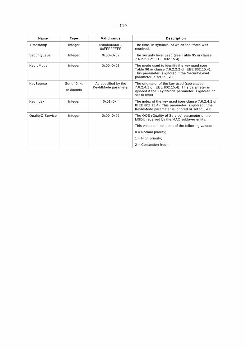
– 119 –
Name Type Valid range Description
Timestamp Integer 0x00000000 – 0xFFFFFFFF
The time, in symbols, at which the frame was received.
SecurityLevel Integer 0x00–0x07 The security level used (see Table 95 in clause 7.6.2.2.1 of IEEE 802.15.4).
KeyIdMode Integer 0x00–0x03 The mode used to identify the key used (see Table 96 in clause 7.6.2.2.2 of IEEE 802.15.4). This parameter is ignored if the SecurityLevel parameter is set to 0x00.
KeySource Set of 0, 4,
or 8octets
As specified by the KeyIdMode parameter
The originator of the key used (see clause 7.6.2.4.1 of IEEE 802.15.4). This parameter is ignored if the KeyIdMode parameter is ignored or set to 0x00.
KeyIndex Integer 0x01–0xff The index of the key used (see clause 7.6.2.4.2 of IEEE 802.15.4). This parameter is ignored if the KeyIdMode parameter is ignored or set to 0x00.
QualityOfService Integer 0x00–0x02 The QOS (Quality of Service) parameter of the MSDU received by the MAC sublayer entity.
This value can take one of the following values:
0 = Normal priority;
1 = High priority;
2 = Contention free;

– 120 –
Annex F 2353 (normative) 2354
2355 MAC acknowledgement 2356
The present specification does not use IEEE802.15.4-2006 MAC acknowledgment frame but 2357 specifies a positive and negative acknowledgments using Frame Control Header (section 5.5 2358 of PHY specification). 2359
The Frame Control Header contains an information used by all stations in the network for 2360 channel access, as well as PHY receiver information used by the destination. For this reason, 2361 Frame Control Header has specific physical layer encoding and modulation as defined in PHY 2362 specification. 2363
Only Frame Control Header will be used as positive (ACK) or negative (NACK) 2364 acknowledgement. 2365
The packet originator may request an acknowledgment by setting Delimiter Type field of 2366 Frame Control Header (section 5.5 of PHY specification). 2367
The receiver will send ACK to the originator if it is requested and the MAC frame was 2368 decoded correctly by PHY. 2369
The receiver will send NACK to the originator if it is requested and the received MAC frame is 2370 corrupted and cannot be recovered by PHY. 2371
ACK and NACK frames contain the 16-bit CRC (MAC FCS field) received in the MAC frame 2372 for which the ACK or NACK response is being sent. These 16 bits are used as ACK or NACK 2373 identifier and located in 2 bytes of FCH (TM[0:7] and PDC) (see 5.5 of PHY specification). 2374 The transmitter will compare against transmitted FCS to determine validity of the response. If 2375 it matches of transmitted FCS, the response is accepted. If it does not match the FCS, the 2376 response is ignored and treated as a collision. 2377
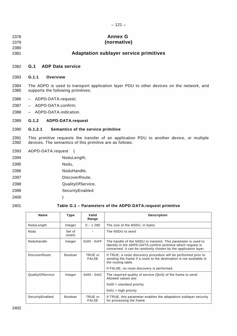
– 121 –
Annex G 2378 (normative) 2379
2380 Adaptation sublayer service primitives 2381
G.1 ADP Data service 2382
G.1.1 Overview 2383
The ADPD is used to transport application layer PDU to other devices on the network, and 2384 supports the following primitives: 2385
– ADPD-DATA.request; 2386
– ADPD-DATA.confirm; 2387
– ADPD-DATA.indication. 2388
G.1.2 ADPD-DATA.request 2389
G.1.2.1 Semantics of the service primitive 2390
This primitive requests the transfer of an application PDU to another device, or multiple 2391 devices. The semantics of this primitive are as follows: 2392
ADPD-DATA.request ( 2393
NsduLength, 2394
Nsdu, 2395
NsduHandle, 2396
DiscoverRoute, 2397
QualityOfService, 2398
SecurityEnabled 2399
) 2400
Table G.1 – Parameters of the ADPD-DATA.request pri mitive 2401
Name Type Valid Range
Description
NsduLength Integer 0 – 1 280 The size of the NSDU, in bytes
Nsdu Set of octets
- The NSDU to send
NsduHandle Integer 0x00 - 0xFF The handle of the NSDU to transmit. This parameter is used to identify in the ADPD-DATA.confirm primitive which request is concerned. It can be randomly chosen by the application layer.
DiscoverRoute Boolean TRUE or FALSE
If TRUE, a route discovery procedure will be performed prior to sending the frame if a route to the destination is not available in the routing table.
If FALSE, no route discovery is performed.
QualityOfService Integer 0x00 - 0x01 The required quality of service (QoS) of the frame to send. Allowed values are:
0x00 = standard priority
0x01 = high priority
SecurityEnabled Boolean TRUE or FALSE
If TRUE, this parameter enables the adaptation sublayer security for processing the frame.
2402

– 122 –
G.1.2.2 When generated 2403
This primitive is generated by the upper layer to request the sending of a given NSDU. 2404
G.1.2.3 Effect on receipt 2405
If this primitive is received when the device has not joined a network, the adaptation sublayer 2406 will issue an ADPD-DATA.confirm primitive with the status INVALID_REQUEST. Else, the 2407 ADPD constructs a 6LoWPAN frame with the following characteristics depending on 2408 transmission mode: 2409
• Case of unicast frame: 2410
– The mesh addressing header is present as described in clause 5.2 of RFC 4944, 2411 where: 2412
– V must be set to 1, to specify that the originator address is a 16-bit network 2413 address; 2414
– F must be set to 1, to specify that the originator address is a 16-bit network 2415 address; 2416
– HopsLft = MaxHops; 2417
– Originator address = The 16-bit network address of the sending device, available in 2418 the NIB; 2419
– Final destination address = 16-bit destination address of the device designated by 2420 the IPv6 address “DstAddr”. 2421
– The broadcast header is not present, 2422
– If necessary, the fragmentation header must be present to transport NPDU which do 2423 not fit in an entire IEEE 802.15.4 frame. In that case, clause 5.3 of RFC 4944 applies, 2424
– LOWPAN_HC1 compressed IPv6 header is present with the following parameters: 2425
– IPv6 Source Address mode = PC-IC (bits 0 and 1 set to 1); 2426
– IPv6 Destination Address mode = PC-IC (bits 2 and 3 set to 1); 2427
– Bit 4 = 1 (no Traffic Class and Flow Label); 2428
– Bits 5 and 6 = value of NsduType. 2429
• Case of multicast frame: 2430
– The mesh addressing header is present as described in part 5.2 of [RFC4944], where 2431
– V must be set to 1, to specify that the originator address is a 16-bit network 2432 address; 2433
– F must be set to 1, to specify that the originator address is a 16-bit network 2434 address; 2435
– HopsLft = MaxHops; 2436
– Originator address = The 16-bit network address of the sending device, available in 2437 the NIB; 2438
– Final destination address = 0xFFFF; 2439
– The broadcast header is present with the following values: 2440
– Sequence Number = previous Sequence Number + 1 2441
– If necessary, the fragmentation header must be present to transport NPDU which do 2442 not fit in an entire IEEE 802.15.4 frame. In that case, clause 5.3 of RFC 4944 applies, 2443
– LOWPAN_HC1 compressed IPv6 header is present with the following parameters: 2444
– IPv6 Source Address mode = PC-IC (bits 0 and 1 set to 1); 2445
– IPv6 Destination Address mode = PC-IC (bits 2 and 3 set to 1); 2446
– Bit 4 = 1 (no Traffic Class and Flow Label); 2447

– 123 –
– Bits 5 and 6 = value of NsduType. 2448
Once the frame is constructed, it is routed according to the procedures described in 7.4.4 2449 (modified clauses 6 of draft-daniel-6lowpan-load-adhoc-routing-03) if the destination address 2450 is a unicast address. If the frame is to be transmitted, the MCPS-Data.request primitive is 2451 invoked, with the following parameters in case of a unicast sending: 2452
– SrcAddrMode = 0x02, for 16-bit address; 2453
– DstAddrMode = 0x02, for 16-bit address; 2454
– SrcPANId = DstPANId = the value of macPANId obtained from the MAC PIB; 2455
– SrcAddr = the value of macShortAddr obtained from the MAC PIB; 2456
– DstAddr = the 16-bit address of the next hop determined by the routing procedure; 2457
– msduLength = the length of the frame, or fragment in case of fragmentation, in 2458 bytes; 2459
– msdu = the frame itself; 2460
– msduHandle = NsduHandle; 2461
– TxOptions: 2462
• b0 = 1 if unicast transmission, 0 otherwise; 2463
• b1 = 0; 2464
• b2 = 0. 2465
– SecurityLevel: 2466
• 0 if SecurityEnabled = FALSE; 2467
• 5 if SecurityEnabled = TRUE; 2468
– KeyIdMode, KeySource : Ignored, 2469
– KeyIndex : Ignored if SecurityLevel=0; Else depends on security policy. 2470
In case of a broadcast (or multicast) frame, the MCPS-Data.request primitive is invoked with 2471 the following parameters: 2472
– SrcAddrMode = 0x02, for 16-bit address; 2473
– DstAddrMode = 0x02, for 16-bit address; 2474
– SrcPANId = DstPANId = the value of macPANId obtained from the MAC PIB; 2475
– SrcAddr = the value of macShortAddr obtained from the MAC PIB; 2476
– DstAddr = 0xFFFF; 2477
– msduLength = the length of the frame, or fragment in case of fragmentation, in 2478 bytes; 2479
– msdu = the frame itself; 2480
– msduHandle = NsduHandle; 2481
– TxOptions: 2482
• b0 = 1 if unicast transmission, 0 otherwise, 2483
• b1 = 0, 2484
• b2 = 0. 2485
– SecurityLevel 2486
• 0 if SecurityEnabled = FALSE, 2487
• 5 if SecurityEnabled = TRUE. 2488
– KeyIdMode, KeySource : Ignored; 2489
– KeyIndex : Ignored if SecurityLevel=0; Else depends on security policy. 2490
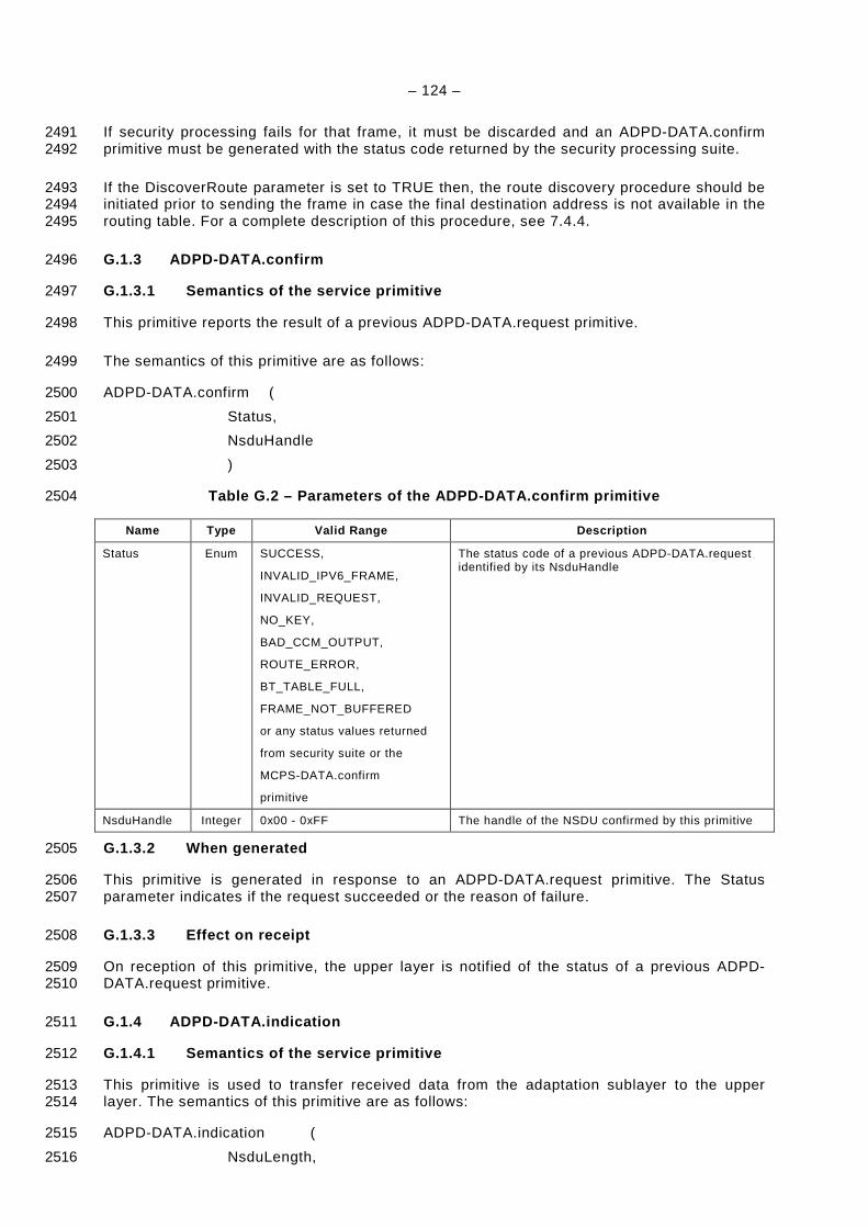
– 124 –
If security processing fails for that frame, it must be discarded and an ADPD-DATA.confirm 2491 primitive must be generated with the status code returned by the security processing suite. 2492
If the DiscoverRoute parameter is set to TRUE then, the route discovery procedure should be 2493 initiated prior to sending the frame in case the final destination address is not available in the 2494 routing table. For a complete description of this procedure, see 7.4.4. 2495
G.1.3 ADPD-DATA.confirm 2496
G.1.3.1 Semantics of the service primitive 2497
This primitive reports the result of a previous ADPD-DATA.request primitive. 2498
The semantics of this primitive are as follows: 2499
ADPD-DATA.confirm ( 2500
Status, 2501
NsduHandle 2502
) 2503
Table G.2 – Parameters of the ADPD-DATA.confirm pri mitive 2504
Name Type Valid Range Description
Status Enum SUCCESS,
INVALID_IPV6_FRAME,
INVALID_REQUEST,
NO_KEY,
BAD_CCM_OUTPUT,
ROUTE_ERROR,
BT_TABLE_FULL,
FRAME_NOT_BUFFERED
or any status values returned
from security suite or the
MCPS-DATA.confirm
primitive
The status code of a previous ADPD-DATA.request identified by its NsduHandle
NsduHandle Integer 0x00 - 0xFF The handle of the NSDU confirmed by this primitive
G.1.3.2 When generated 2505
This primitive is generated in response to an ADPD-DATA.request primitive. The Status 2506 parameter indicates if the request succeeded or the reason of failure. 2507
G.1.3.3 Effect on receipt 2508
On reception of this primitive, the upper layer is notified of the status of a previous ADPD-2509 DATA.request primitive. 2510
G.1.4 ADPD-DATA.indication 2511
G.1.4.1 Semantics of the service primitive 2512
This primitive is used to transfer received data from the adaptation sublayer to the upper 2513 layer. The semantics of this primitive are as follows: 2514
ADPD-DATA.indication ( 2515
NsduLength, 2516

– 125 –
Nsdu, 2517
LinkQualityIndicator, 2518
SecurityEnabled 2519
) 2520
Table G.3 – Parameters of the ADPD-DATA.indication primitive 2521
Name Type Valid Range Description
NsduLength Integer 0-1280 The size of the NSDU, in bytes
Nsdu Set of octets
- The received NSDU
LinkQualityIndicator Integer 0x00-0xFF The value of the link quality during reception of the frame
SecurityEnabled Boolean TRUE or FALSE
TRUE if the frame was received using security.
G.1.4.2 When generated 2522
This primitive is generated by the adaptation sublayer when a valid data frame whose final 2523 destination is the current station has been received. 2524
G.1.4.3 Effect on receipt 2525
On generation of this primitive, the upper layer is notified of the arrival of a data frame. 2526
G.2 ADP Management service 2527
G.2.1 Overview 2528
The ADPM allows the transport of command frames used for network maintenance. The list of 2529 primitives supported by the ADPM is: 2530
– ADPM-DISCOVERY.request; 2531
– ADPM-DISCOVERY.confirm; 2532
– ADPM-NETWORK-START.request; 2533
– ADPM-NETWORK-START.confirm; 2534
– ADPM-NETWORK-JOIN.request; 2535
– ADPM-NETWORK-JOIN.confirm; 2536
– ADPM-NETWORK-JOIN.indication; 2537
– ADPM-NETWORK-LEAVE.request; 2538
– ADPM-NETWORK-LEAVE.indication; 2539
– ADPM-NETWORK-LEAVE.confirm; 2540
– ADPM-RESET.request; 2541
– ADPM-RESET.confirm; 2542
– ADPM-GET.request; 2543
– ADPM-GET.confirm; 2544
– ADPM-SET.request; 2545
– ADPM-SET.confirm; 2546
– ADPM-NETWORK-STATUS.indication; 2547
– ADPM-ROUTE-DISCOVERY.request; 2548
– ADPM-ROUTE-DISCOVERY.confirm. 2549

– 126 –
G.2.2 ADPM-DISCOVERY.request 2550
G.2.2.1 Semantics of the service primitive 2551
This primitive allows the upper layer to request the ADPM to scan for networks operating in its 2552 POS. 2553
The semantics of this primitive are as follows: 2554
ADPM-DISCOVERY.request ( 2555
Duration, 2556
) 2557
Table G.4 – Parameters of the ADPM-DISCOVERY.reques t primitive 2558
Name Type Valid Range Description
Duration Integer 0x00-0xFF The number of seconds the active scan must last
G.2.2.2 When generated 2559
This primitive is generated by the next upper layer to get informed of the current networks 2560 operating in the POS of the device. 2561
G.2.2.3 Effect on receipt 2562
On receipt of this primitive, the ADP layer will initiate an active scan by invoking the MLME-2563 SCAN.request with the following parameters: 2564
– ScanType = 0x01 for active scan; 2565
– ScanChannels = all bits set to 0 (not used); 2566
– ScanDuration = Duration; 2567
– ChannelPage = 0 (not used); 2568
– SecurityLevel = 0; 2569
– KeyIdMode, KeySource and KeyIndex: Ignored. 2570
On receipt of the MLME-SCAN.confirm primitive, the ADP layer issues an ADPM-2571 DISCOVERY.confirm primitive containing the PAN ID of all the PANs operating in the POS of 2572 the device, or an error code. 2573
G.2.3 ADPM-DISCOVERY.confirm 2574
G.2.3.1 Semantics of the service primitive 2575
This primitive is generated by the ADP layer upon completion of a previous ADPM-2576 DISCOVERY.request. 2577
The semantics of this primitive are as follows: 2578
ADPM-DISCOVERY.confirm ( 2579
Status, 2580
PANCount, 2581
PANDescriptor 2582
) 2583
Table G.5 – Parameters of the ADPM-DISCOVERY.confir m primitive 2584
Name Type Valid Range Description
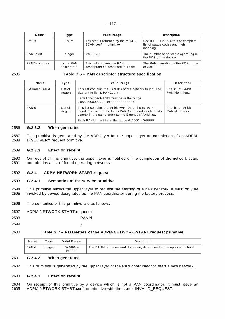
– 127 –
Name Type Valid Range Description
Status Enum Any status returned by the MLME-SCAN.confirm primitive
See IEEE 802.15.4 for the complete list of status codes and their meaning
PANCount Integer 0x00-0xFF The number of networks operating in the POS of the device
PANDescriptior List of PAN descriptors
This list contains the PAN descriptors as described in Table .
The PAN operating in the POS of the device
Table G.6 – PAN descriptor structure specification 2585
Name Type Valid Range Description
ExtendedPANId List of integers
This list contains the PAN IDs of the network found. The size of the list is PANCount.
Each ExtendedPANId must be in the range 0x000000000001 – 0xFFFFFFFFFFFE
The list of 64-bit PAN identifiers.
PANId List of integers
This list contains the 16-bit PAN IDs of the network found. The size of the list is PANCount, and its elements appear in the same order as the ExtendedPANId list.
Each PANId must be in the range 0x0000 – 0xFFFF
The list of 16-bit PAN identifiers.
G.2.3.2 When generated 2586
This primitive is generated by the ADP layer for the upper layer on completion of an ADPM-2587 DISCOVERY.request primitive. 2588
G.2.3.3 Effect on receipt 2589
On receipt of this primitive, the upper layer is notified of the completion of the network scan, 2590 and obtains a list of found operating networks. 2591
G.2.4 ADPM-NETWORK-START.request 2592
G.2.4.1 Semantics of the service primitive 2593
This primitive allows the upper layer to request the starting of a new network. It must only be 2594 invoked by device designated as the PAN coordinator during the factory process. 2595
The semantics of this primitive are as follows: 2596
ADPM-NETWORK-START.request ( 2597
PANId 2598
) 2599
Table G.7 – Parameters of the ADPM-NETWORK-START.re quest primitive 2600
Name Type Valid Range Description
PANId Integer 0x0000 – 0xFFFF
The PANId of the network to create, determined at the application level
G.2.4.2 When generated 2601
This primitive is generated by the upper layer of the PAN coordinator to start a new network. 2602
G.2.4.3 Effect on receipt 2603
On receipt of this primitive by a device which is not a PAN coordinator, it must issue an 2604 ADPM-NETWORK-START.confirm primitive with the status INVALID_REQUEST. 2605
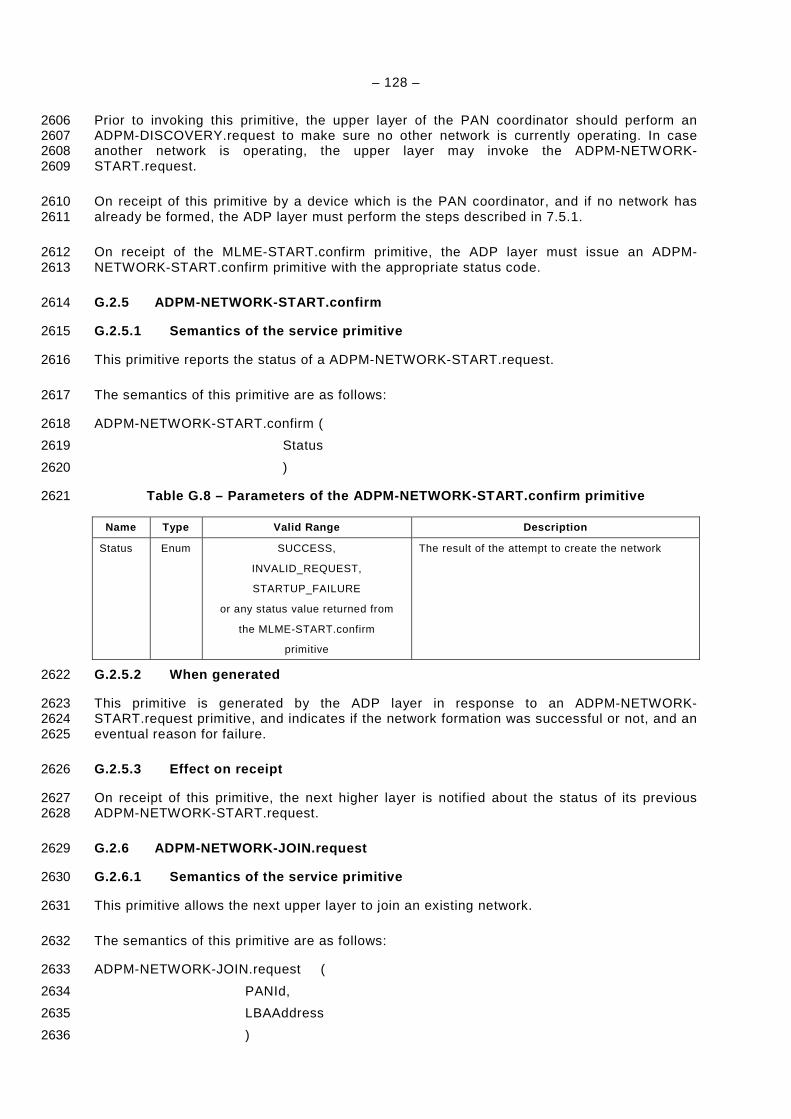
– 128 –
Prior to invoking this primitive, the upper layer of the PAN coordinator should perform an 2606 ADPM-DISCOVERY.request to make sure no other network is currently operating. In case 2607 another network is operating, the upper layer may invoke the ADPM-NETWORK-2608 START.request. 2609
On receipt of this primitive by a device which is the PAN coordinator, and if no network has 2610 already be formed, the ADP layer must perform the steps described in 7.5.1. 2611
On receipt of the MLME-START.confirm primitive, the ADP layer must issue an ADPM-2612 NETWORK-START.confirm primitive with the appropriate status code. 2613
G.2.5 ADPM-NETWORK-START.confirm 2614
G.2.5.1 Semantics of the service primitive 2615
This primitive reports the status of a ADPM-NETWORK-START.request. 2616
The semantics of this primitive are as follows: 2617
ADPM-NETWORK-START.confirm ( 2618
Status 2619
) 2620
Table G.8 – Parameters of the ADPM-NETWORK-START.co nfirm primitive 2621
Name Type Valid Range Description
Status Enum SUCCESS,
INVALID_REQUEST,
STARTUP_FAILURE
or any status value returned from
the MLME-START.confirm
primitive
The result of the attempt to create the network
G.2.5.2 When generated 2622
This primitive is generated by the ADP layer in response to an ADPM-NETWORK-2623 START.request primitive, and indicates if the network formation was successful or not, and an 2624 eventual reason for failure. 2625
G.2.5.3 Effect on receipt 2626
On receipt of this primitive, the next higher layer is notified about the status of its previous 2627 ADPM-NETWORK-START.request. 2628
G.2.6 ADPM-NETWORK-JOIN.request 2629
G.2.6.1 Semantics of the service primitive 2630
This primitive allows the next upper layer to join an existing network. 2631
The semantics of this primitive are as follows: 2632
ADPM-NETWORK-JOIN.request ( 2633
PANId, 2634
LBAAddress 2635
) 2636
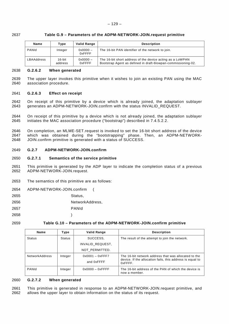
– 129 –
Table G.9 – Parameters of the ADPM-NETWORK-JOIN.req uest primitive 2637
Name Type Valid Range Description
PANId Integer 0x0000 –0xFFFF
The 16-bit PAN identifier of the network to join.
LBAAddress 16-bit address
0x0000 –0xFFFF
The 16-bit short address of the device acting as a LoWPAN Bootstrap Agent as defined in draft-6lowpan-commissioning-02.
G.2.6.2 When generated 2638
The upper layer invokes this primitive when it wishes to join an existing PAN using the MAC 2639 association procedure. 2640
G.2.6.3 Effect on receipt 2641
On receipt of this primitive by a device which is already joined, the adaptation sublayer 2642 generates an ADPM-NETWORK-JOIN.confirm with the status INVALID_REQUEST. 2643
On receipt of this primitive by a device which is not already joined, the adaptation sublayer 2644 initiates the MAC association procedure (“bootstrap”) described in 7.4.5.2.2. 2645
On completion, an MLME-SET.request is invoked to set the 16-bit short address of the device 2646 which was obtained during the “bootstrapping” phase. Then, an ADPM-NETWORK-2647 JOIN.confirm primitive is generated with a status of SUCCESS. 2648
G.2.7 ADPM-NETWORK-JOIN.confirm 2649
G.2.7.1 Semantics of the service primitive 2650
This primitive is generated by the ADP layer to indicate the completion status of a previous 2651 ADPM-NETWORK-JOIN.request. 2652
The semantics of this primitive are as follows: 2653
ADPM-NETWORK-JOIN.confirm ( 2654
Status, 2655
NetworkAddress, 2656
PANId 2657
) 2658
Table G.10 – Parameters of the ADPM-NETWORK-JOIN.co nfirm primitive 2659
Name Type Valid Range Description
Status Status SUCCESS,
INVALID_REQUEST,
NOT_PERMITTED.
The result of the attempt to join the network.
NetworkAddress Integer 0x0001 – 0xFFF7
and 0xFFFF
The 16-bit network address that was allocated to the device. If the allocation fails, this address is equal to 0xFFFF.
PANId Integer 0x0000 – 0xFFFF The 16-bit address of the PAN of which the device is now a member.
G.2.7.2 When generated 2660
This primitive is generated in response to an ADPM-NETWORK-JOIN.request primitive, and 2661 allows the upper layer to obtain information on the status of its request. 2662
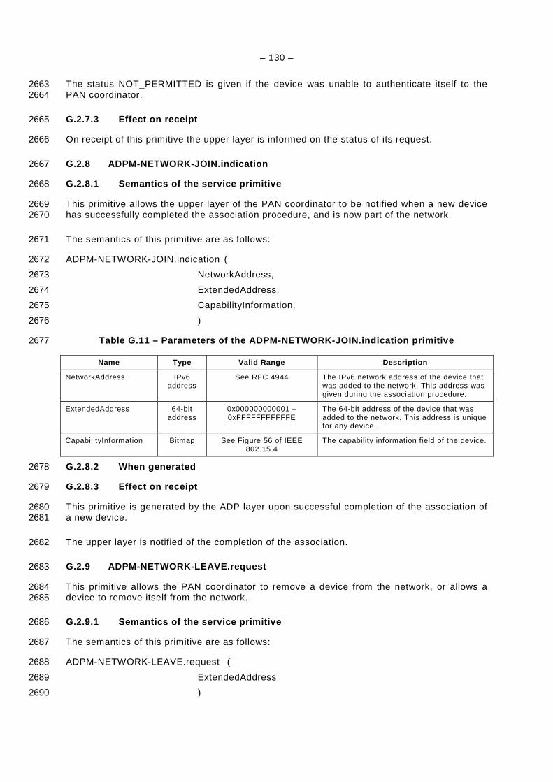
– 130 –
The status NOT_PERMITTED is given if the device was unable to authenticate itself to the 2663 PAN coordinator. 2664
G.2.7.3 Effect on receipt 2665
On receipt of this primitive the upper layer is informed on the status of its request. 2666
G.2.8 ADPM-NETWORK-JOIN.indication 2667
G.2.8.1 Semantics of the service primitive 2668
This primitive allows the upper layer of the PAN coordinator to be notified when a new device 2669 has successfully completed the association procedure, and is now part of the network. 2670
The semantics of this primitive are as follows: 2671
ADPM-NETWORK-JOIN.indication ( 2672
NetworkAddress, 2673
ExtendedAddress, 2674
CapabilityInformation, 2675
) 2676
Table G.11 – Parameters of the ADPM-NETWORK-JOIN.in dication primitive 2677
Name Type Valid Range Description
NetworkAddress IPv6 address
See RFC 4944 The IPv6 network address of the device that was added to the network. This address was given during the association procedure.
ExtendedAddress 64-bit address
0x000000000001 – 0xFFFFFFFFFFFE
The 64-bit address of the device that was added to the network. This address is unique for any device.
CapabilityInformation Bitmap See Figure 56 of IEEE 802.15.4
The capability information field of the device.
G.2.8.2 When generated 2678
G.2.8.3 Effect on receipt 2679
This primitive is generated by the ADP layer upon successful completion of the association of 2680 a new device. 2681
The upper layer is notified of the completion of the association. 2682
G.2.9 ADPM-NETWORK-LEAVE.request 2683
This primitive allows the PAN coordinator to remove a device from the network, or allows a 2684 device to remove itself from the network. 2685
G.2.9.1 Semantics of the service primitive 2686
The semantics of this primitive are as follows: 2687
ADPM-NETWORK-LEAVE.request ( 2688
ExtendedAddress 2689
) 2690
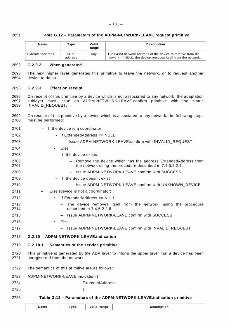
– 131 –
Table G.12 – Parameters of the ADPM-NETWORK-LEAVE.r equest primitive 2691
Name Type Valid Range
Description
ExtendedAddress 64-bit address
Any The 64-bit network address of the device to remove from the network. If NULL, the device removes itself from the network.
G.2.9.2 When generated 2692
The next higher layer generates this primitive to leave the network, or to request another 2693 device to do so. 2694
G.2.9.3 Effect on receipt 2695
On receipt of this primitive by a device which is not associated to any network, the adaptation 2696 sublayer must issue an ADPM-NETWORK-LEAVE.confirm primitive with the status 2697 INVALID_REQUEST. 2698
On receipt of this primitive by a device which is associated to any network, the following steps 2699 must be performed: 2700
– If the device is a coordinator 2701
• If ExtendedAddress == NULL 2702
– Issue ADPM-NETWORK-LEAVE.confirm with INVALID_REQUEST 2703
• Else 2704
– If the device exists 2705
– Remove the device which has the address ExtendedAddress from 2706 the network using the procedure described in 7.4.5.2.2.7. 2707
– Issue ADPM-NETWORK-LEAVE.confirm with SUCCESS 2708
– If the device doesn’t exist 2709
– Issue ADPM-NETWORK-LEAVE.confirm with UNKNOWN_DEVICE 2710
– Else (device is not a coordinator) 2711
• If ExtendedAddress == NULL 2712
– The device removes itself from the network, using the procedure 2713 described in 7.4.5.2.2.8. 2714
– Issue ADPM-NETWORK-LEAVE.confirm with SUCCESS 2715
• Else 2716
– Issue ADPM-NETWORK-LEAVE.confirm with INVALID_REQUEST 2717
G.2.10 ADPM-NETWORK-LEAVE.indication 2718
G.2.10.1 Semantics of the service primitive 2719
This primitive is generated by the ADP layer to inform the upper layer that a device has been 2720 unregistered from the network. 2721
The semantics of this primitive are as follows: 2722
ADPM-NETWORK-LEAVE.indication ( 2723
ExtendedAddress, 2724
) 2725
Table G.13 – Parameters of the ADPM-NETWORK-LEAVE.i ndication primitive 2726
Name Type Valid Range Description
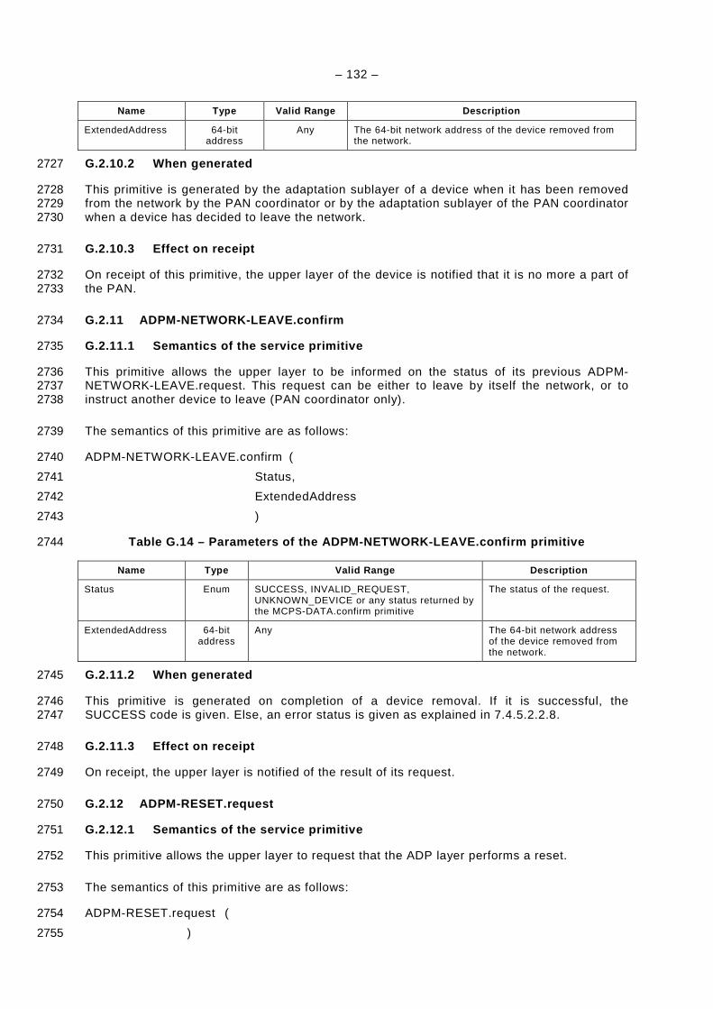
– 132 –
Name Type Valid Range Description
ExtendedAddress 64-bit address
Any The 64-bit network address of the device removed from the network.
G.2.10.2 When generated 2727
This primitive is generated by the adaptation sublayer of a device when it has been removed 2728 from the network by the PAN coordinator or by the adaptation sublayer of the PAN coordinator 2729 when a device has decided to leave the network. 2730
G.2.10.3 Effect on receipt 2731
On receipt of this primitive, the upper layer of the device is notified that it is no more a part of 2732 the PAN. 2733
G.2.11 ADPM-NETWORK-LEAVE.confirm 2734
G.2.11.1 Semantics of the service primitive 2735
This primitive allows the upper layer to be informed on the status of its previous ADPM-2736 NETWORK-LEAVE.request. This request can be either to leave by itself the network, or to 2737 instruct another device to leave (PAN coordinator only). 2738
The semantics of this primitive are as follows: 2739
ADPM-NETWORK-LEAVE.confirm ( 2740
Status, 2741
ExtendedAddress 2742
) 2743
Table G.14 – Parameters of the ADPM-NETWORK-LEAVE.c onfirm primitive 2744
Name Type Valid Range Description
Status Enum SUCCESS, INVALID_REQUEST, UNKNOWN_DEVICE or any status returned by the MCPS-DATA.confirm primitive
The status of the request.
ExtendedAddress 64-bit address
Any The 64-bit network address of the device removed from the network.
G.2.11.2 When generated 2745
This primitive is generated on completion of a device removal. If it is successful, the 2746 SUCCESS code is given. Else, an error status is given as explained in 7.4.5.2.2.8. 2747
G.2.11.3 Effect on receipt 2748
On receipt, the upper layer is notified of the result of its request. 2749
G.2.12 ADPM-RESET.request 2750
G.2.12.1 Semantics of the service primitive 2751
This primitive allows the upper layer to request that the ADP layer performs a reset. 2752
The semantics of this primitive are as follows: 2753
ADPM-RESET.request ( 2754
) 2755
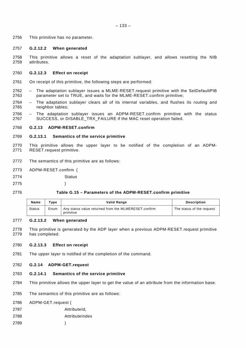
– 133 –
This primitive has no parameter. 2756
G.2.12.2 When generated 2757
This primitive allows a reset of the adaptation sublayer, and allows resetting the NIB 2758 attributes. 2759
G.2.12.3 Effect on receipt 2760
On receipt of this primitive, the following steps are performed: 2761
– The adaptation sublayer issues a MLME-RESET.request primitive with the SetDefaultPIB 2762 parameter set to TRUE, and waits for the MLME-RESET.confirm primitive; 2763
– The adaptation sublayer clears all of its internal variables, and flushes its routing and 2764 neighbor tables; 2765
– The adaptation sublayer issues an ADPM-RESET.confirm primitive with the status 2766 SUCCESS, or DISABLE_TRX_FAILURE if the MAC reset operation failed. 2767
G.2.13 ADPM-RESET.confirm 2768
G.2.13.1 Semantics of the service primitive 2769
This primitive allows the upper layer to be notified of the completion of an ADPM-2770 RESET.request primitive. 2771
The semantics of this primitive are as follows: 2772
ADPM-RESET.confirm ( 2773
Status 2774
) 2775
Table G.15 – Parameters of the ADPM-RESET.confirm p rimitive 2776
Name Type Valid Range Description
Status Enum Any status value returned from the MLMERESET.confirm primitive
The status of the request
G.2.13.2 When generated 2777
This primitive is generated by the ADP layer when a previous ADPM-RESET.request primitive 2778 has completed. 2779
G.2.13.3 Effect on receipt 2780
The upper layer is notified of the completion of the command. 2781
G.2.14 ADPM-GET.request 2782
G.2.14.1 Semantics of the service primitive 2783
This primitive allows the upper layer to get the value of an attribute from the information base. 2784
The semantics of this primitive are as follows: 2785
ADPM-GET.request ( 2786
AttributeId, 2787
AttributeIndex 2788
) 2789

– 134 –
Table G.16 – Parameters of the ADPM-GET.request pri mitive 2790
Name Type Valid Range Description
AttributeId Integer See clause 7.4.2 The identifier of the IB attribute to read
AttributeIndex Integer Depends on attribute, see 7.4.2
The index within the table of the specified IB attribute to read. This parameter is valid only for IB attributes that are tables.
G.2.14.2 When generated 2791
This primitive is generated by the upper layer to read the value of an attribute from the IB. 2792
G.2.14.3 Effect on receipt 2793
On receipt of this primitive, the adaptation sublayer attempts to retrieve the selected attribute 2794 in the information base. If the attribute is not found, the adaptation layer generates an ADPM-2795 GET.confirm primitive with the status UNSUPPORTED_ATTRIBUTE. If the attribute is found 2796 (and is a table), but the AttributeIndex is out of range, the adaptation layer generates an 2797 ADPM-GET.confirm primitive with the status INVALID_INDEX. 2798
Else, the adaptation sublayer generates an ADPM-GET.confirm primitive with the status 2799 SUCCESS, and the value read from the IB in the AttributeValue parameter. 2800
G.2.15 ADPM-GET.confirm 2801
G.2.15.1 Semantics of the service primitive 2802
This primitive allows the upper layer to be informed of the status of a previously issued 2803 ADPM-GET.request primitive. 2804
The semantics of this primitive are as follows: 2805
ADPM-GET.confirm ( 2806
Status, 2807
AttributeId, 2808
AttributeIndex, 2809
AttributeValue 2810
) 2811
Table G.17 – Parameters of the ADPM-GET.confirm pri mitive 2812
Name Type Valid Range Description
Status Enum SUCCESS,
UNSUPPORTED_ATTRIBUTE
or INVALID_INDEX
The status of the reading.
AttributeId Integer See 7.4.2 The identifier of the IB attribute read.
AttributeIndex Integer Depends on attribute, see 7.4.2 The index within the table of the specified IB attribute read. This parameter is valid only for IB attributes that are tables.
AttributeValue Various Attribute specific The value of the attribute read from the IB.
G.2.15.2 When generated 2813
This primitive is generated by the adaptation sublayer in response to an ADPM-GET.request 2814 primitive. 2815
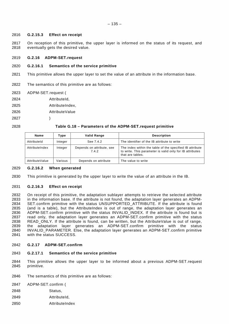
– 135 –
G.2.15.3 Effect on receipt 2816
On reception of this primitive, the upper layer is informed on the status of its request, and 2817 eventually gets the desired value. 2818
G.2.16 ADPM-SET.request 2819
G.2.16.1 Semantics of the service primitive 2820
This primitive allows the upper layer to set the value of an attribute in the information base. 2821
The semantics of this primitive are as follows: 2822
ADPM-SET.request ( 2823
AttributeId, 2824
AttributeIndex, 2825
AttributeValue 2826
) 2827
Table G.18 – Parameters of the ADPM-SET.request pri mitive 2828
Name Type Valid Range Description
AttributeId Integer See 7.4.2 The identifier of the IB attribute to write
AttributeIndex Integer Depends on attribute, see 7.4.2
The index within the table of the specified IB attribute to write. This parameter is valid only for IB attributes that are tables.
AttributeValue Various Depends on attribute The value to write
G.2.16.2 When generated 2829
This primitive is generated by the upper layer to write the value of an attribute in the IB. 2830
G.2.16.3 Effect on receipt 2831
On receipt of this primitive, the adaptation sublayer attempts to retrieve the selected attribute 2832 in the information base. If the attribute is not found, the adaptation layer generates an ADPM-2833 SET.confirm primitive with the status UNSUPPORTED_ATTRIBUTE. If the attribute is found 2834 (and is a table), but the AttributeIndex is out of range, the adaptation layer generates an 2835 ADPM-SET.confirm primitive with the status INVALID_INDEX. If the attribute is found but is 2836 read only, the adaptation layer generates an ADPM-SET.confirm primitive with the status 2837 READ_ONLY. If the attribute is found, can be written, but the AttributeValue is out of range, 2838 the adaptation layer generates an ADPM-SET.confirm primitive with the status 2839 INVALID_PARAMETER. Else, the adaptation layer generates an ADPM-SET.confirm primitive 2840 with the status SUCCESS. 2841
G.2.17 ADPM-SET.confirm 2842
G.2.17.1 Semantics of the service primitive 2843
This primitive allows the upper layer to be informed about a previous ADPM-SET.request 2844 primitive. 2845
The semantics of this primitive are as follows: 2846
ADPM-SET.confirm ( 2847
Status, 2848
AttributeId, 2849
AttributeIndex 2850
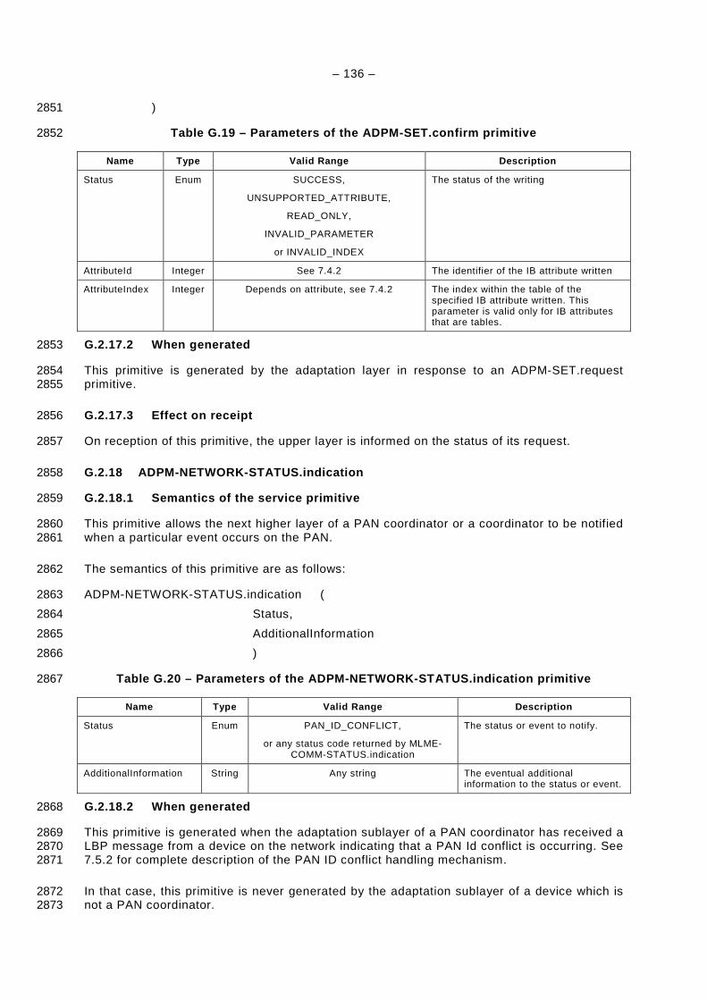
– 136 –
) 2851
Table G.19 – Parameters of the ADPM-SET.confirm pri mitive 2852
Name Type Valid Range Description
Status Enum SUCCESS,
UNSUPPORTED_ATTRIBUTE,
READ_ONLY,
INVALID_PARAMETER
or INVALID_INDEX
The status of the writing
AttributeId Integer See 7.4.2 The identifier of the IB attribute written
AttributeIndex Integer Depends on attribute, see 7.4.2 The index within the table of the specified IB attribute written. This parameter is valid only for IB attributes that are tables.
G.2.17.2 When generated 2853
This primitive is generated by the adaptation layer in response to an ADPM-SET.request 2854 primitive. 2855
G.2.17.3 Effect on receipt 2856
On reception of this primitive, the upper layer is informed on the status of its request. 2857
G.2.18 ADPM-NETWORK-STATUS.indication 2858
G.2.18.1 Semantics of the service primitive 2859
This primitive allows the next higher layer of a PAN coordinator or a coordinator to be notified 2860 when a particular event occurs on the PAN. 2861
The semantics of this primitive are as follows: 2862
ADPM-NETWORK-STATUS.indication ( 2863
Status, 2864
AdditionalInformation 2865
) 2866
Table G.20 – Parameters of the ADPM-NETWORK-STATUS. indication primitive 2867
Name Type Valid Range Description
Status Enum PAN_ID_CONFLICT,
or any status code returned by MLME-COMM-STATUS.indication
The status or event to notify.
AdditionalInformation String Any string The eventual additional information to the status or event.
G.2.18.2 When generated 2868
This primitive is generated when the adaptation sublayer of a PAN coordinator has received a 2869 LBP message from a device on the network indicating that a PAN Id conflict is occurring. See 2870 7.5.2 for complete description of the PAN ID conflict handling mechanism. 2871
In that case, this primitive is never generated by the adaptation sublayer of a device which is 2872 not a PAN coordinator. 2873
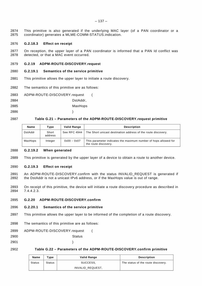
– 137 –
This primitive is also generated if the underlying MAC layer (of a PAN coordinator or a 2874 coordinator) generates a MLME-COMM-STATUS.indication. 2875
G.2.18.3 Effect on receipt 2876
On reception, the upper layer of a PAN coordinator is informed that a PAN Id conflict was 2877 detected, or that a MAC event occurred. 2878
G.2.19 ADPM-ROUTE-DISCOVERY.request 2879
G.2.19.1 Semantics of the service primitive 2880
This primitive allows the upper layer to initiate a route discovery. 2881
The semantics of this primitive are as follows: 2882
ADPM-ROUTE-DISCOVERY.request ( 2883
DstAddr, 2884
MaxHops 2885
) 2886
Table G.21 – Parameters of the ADPM-ROUTE-DISCOVERY .request primitive 2887
Name Type Valid Range Description
DstAddr Short address
See RFC 4944 The Short unicast destination address of the route discovery.
MaxHops Integer 0x00 – 0x07 This parameter indicates the maximum number of hops allowed for the route discovery.
G.2.19.2 When generated 2888
This primitive is generated by the upper layer of a device to obtain a route to another device. 2889
G.2.19.3 Effect on receipt 2890
An ADPM-ROUTE-DISCOVERY.confirm with the status INVALID_REQUEST is generated if 2891 the DstAddr is not a unicast IPv6 address, or if the MaxHops value is out of range. 2892
On receipt of this primitive, the device will initiate a route discovery procedure as described in 2893 7.4.4.2.3. 2894
G.2.20 ADPM-ROUTE-DISCOVERY.confirm 2895
G.2.20.1 Semantics of the service primitive 2896
This primitive allows the upper layer to be informed of the completion of a route discovery. 2897
The semantics of this primitive are as follows: 2898
ADPM-ROUTE-DISCOVERY.request ( 2899
Status 2900
) 2901
Table G.22 – Parameters of the ADPM-ROUTE-DISCOVERY .confirm primitive 2902
Name Type Valid Range Description
Status Status SUCCESS,
INVALID_REQUEST,
The status of the route discovery.
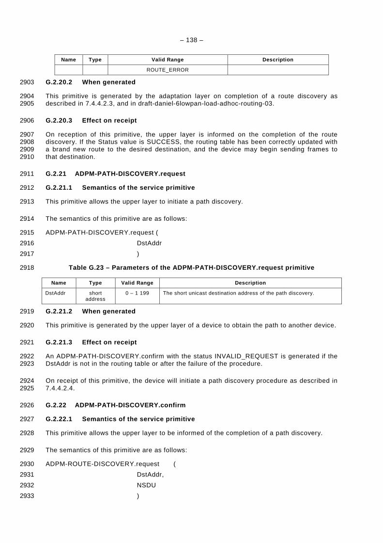
– 138 –
Name Type Valid Range Description
ROUTE_ERROR
G.2.20.2 When generated 2903
This primitive is generated by the adaptation layer on completion of a route discovery as 2904 described in 7.4.4.2.3, and in draft-daniel-6lowpan-load-adhoc-routing-03. 2905
G.2.20.3 Effect on receipt 2906
On reception of this primitive, the upper layer is informed on the completion of the route 2907 discovery. If the Status value is SUCCESS, the routing table has been correctly updated with 2908 a brand new route to the desired destination, and the device may begin sending frames to 2909 that destination. 2910
G.2.21 ADPM-PATH-DISCOVERY.request 2911
G.2.21.1 Semantics of the service primitive 2912
This primitive allows the upper layer to initiate a path discovery. 2913
The semantics of this primitive are as follows: 2914
ADPM-PATH-DISCOVERY.request ( 2915
DstAddr 2916
) 2917
Table G.23 – Parameters of the ADPM-PATH-DISCOVERY. request primitive 2918
Name Type Valid Range Description
DstAddr short address
0 – 1 199 The short unicast destination address of the path discovery.
G.2.21.2 When generated 2919
This primitive is generated by the upper layer of a device to obtain the path to another device. 2920
G.2.21.3 Effect on receipt 2921
An ADPM-PATH-DISCOVERY.confirm with the status INVALID_REQUEST is generated if the 2922 DstAddr is not in the routing table or after the failure of the procedure. 2923
On receipt of this primitive, the device will initiate a path discovery procedure as described in 2924 7.4.4.2.4. 2925
G.2.22 ADPM-PATH-DISCOVERY.confirm 2926
G.2.22.1 Semantics of the service primitive 2927
This primitive allows the upper layer to be informed of the completion of a path discovery. 2928
The semantics of this primitive are as follows: 2929
ADPM-ROUTE-DISCOVERY.request ( 2930
DstAddr, 2931
NSDU 2932
) 2933
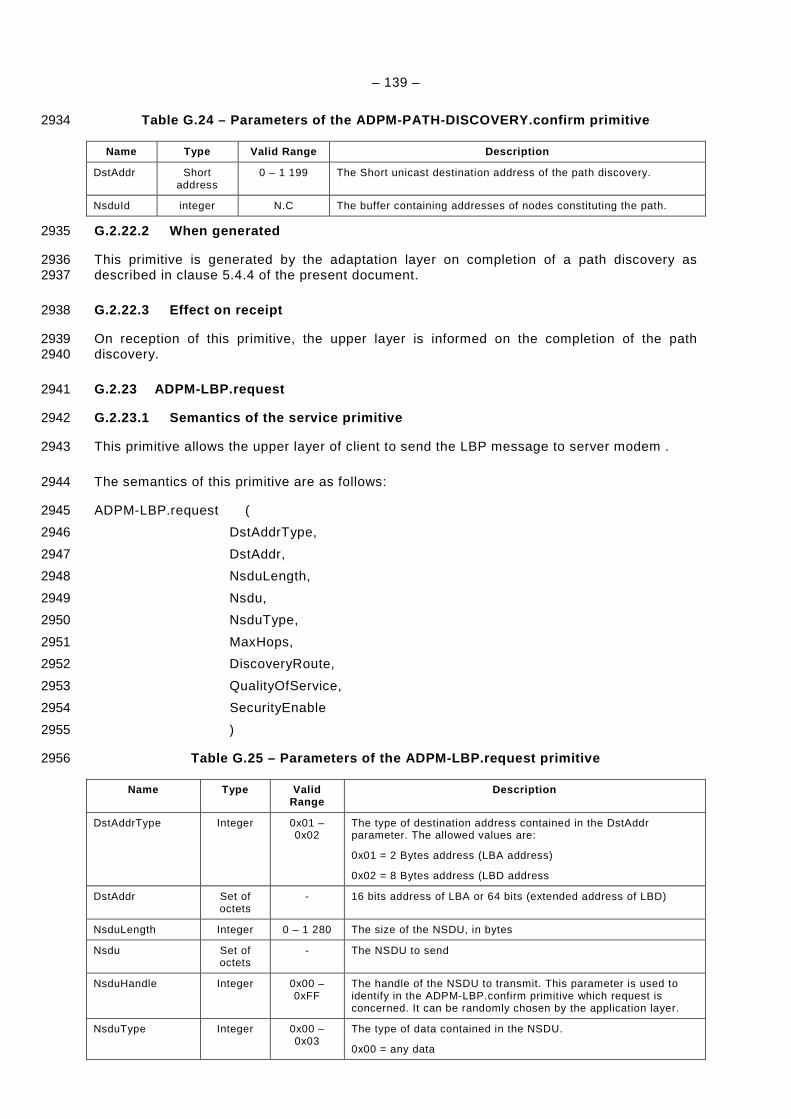
– 139 –
Table G.24 – Parameters of the ADPM-PATH-DISCOVERY. confirm primitive 2934
Name Type Valid Range Description
DstAddr Short address
0 – 1 199 The Short unicast destination address of the path discovery.
NsduId integer N.C The buffer containing addresses of nodes constituting the path.
G.2.22.2 When generated 2935
This primitive is generated by the adaptation layer on completion of a path discovery as 2936 described in clause 5.4.4 of the present document. 2937
G.2.22.3 Effect on receipt 2938
On reception of this primitive, the upper layer is informed on the completion of the path 2939 discovery. 2940
G.2.23 ADPM-LBP.request 2941
G.2.23.1 Semantics of the service primitive 2942
This primitive allows the upper layer of client to send the LBP message to server modem . 2943
The semantics of this primitive are as follows: 2944
ADPM-LBP.request ( 2945
DstAddrType, 2946
DstAddr, 2947
NsduLength, 2948
Nsdu, 2949
NsduType, 2950
MaxHops, 2951
DiscoveryRoute, 2952
QualityOfService, 2953
SecurityEnable 2954
) 2955
Table G.25 – Parameters of the ADPM-LBP.request pri mitive 2956
Name Type Valid Range
Description
DstAddrType Integer 0x01 – 0x02
The type of destination address contained in the DstAddr parameter. The allowed values are:
0x01 = 2 Bytes address (LBA address)
0x02 = 8 Bytes address (LBD address
DstAddr Set of octets
- 16 bits address of LBA or 64 bits (extended address of LBD)
NsduLength Integer 0 – 1 280 The size of the NSDU, in bytes
Nsdu Set of octets
- The NSDU to send
NsduHandle Integer 0x00 – 0xFF
The handle of the NSDU to transmit. This parameter is used to identify in the ADPM-LBP.confirm primitive which request is concerned. It can be randomly chosen by the application layer.
NsduType Integer 0x00 – 0x03
The type of data contained in the NSDU.
0x00 = any data

– 140 –
Name Type Valid Range
Description
0x01 = UDP
0x02 = ICMP
0x03 = TCP
MaxHops Integer 0x00 –0x07
The number of times the frame will be repeated by network routers.
DiscoveryRoute Boolean TRUE –FALSE
If TRUE, a route discovery procedure will be performed prior to sending the frame if a route to the destination is not available in the routing table.
If FALSE, no route discovery is performed.
QualityOfService Integer 0x00 –0x01
The required quality of service (QoS) of the frame to send. Allowed values are:
0x00 = standard priority
0x01 = high priority
SecurityEnabled Boolean TRUE –FALSE
If TRUE, this parameter enables the ADP layer security for processing the frame.
G.2.23.2 When generated 2957
This primitive is generated by the client LBPServer to perform the authentication, re-keying 2958 and leave procedure. 2959
G.2.23.3 Effect on receipt 2960
On reception of this primitive, the modem sends the coming frame to the destination. 2961
G.2.24 ADPM-LBP.confirm 2962
G.2.24.1 Semantics of the service primitive 2963
This primitive reports the result of a previous ADPM-LBP.request primitive. 2964
The semantics of this primitive are as follows: 2965
ADPM-LBP.confirm ( 2966
Status, 2967
NsduHandle, 2968
) 2969
Table G.26 – Parameters of the ADPM-LBP.confirm pri mitive 2970
Name Type Valid Range Description
Status Enum
SUCCESS,
INVALID_REQUEST,
NO_KEY,
BAD_CCM_OUTPUT,
ROUTE_ERROR,
BT_TABLE_FULL,
FRAME_NOT_BUFFERED
or any status values returned
from security suite or the
MCPS-DATA.confirm
primitive
The status code of a previous ADPM-LBP.request identified by its NsduHandle.
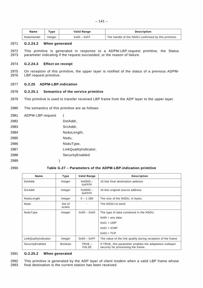
– 141 –
Name Type Valid Range Description
NsduHandel Integer 0x00 – 0xFF The handle of the NSDU confirmed by this primitive.
G.2.24.2 When generated 2971
This primitive is generated in response to a ADPM-LBP.request primitive, the Status 2972 parameter indicating if the request succeeded, or the reason of failure. 2973
G.2.24.3 Effect on receipt 2974
On reception of this primitive, the upper layer is notified of the status of a previous ADPM-2975 LBP.request primitive. 2976
G.2.25 ADPM-LBP.indication 2977
G.2.25.1 Semantics of the service primitive 2978
This primitive is used to transfer received LBP frame from the ADP layer to the upper layer. 2979
The semantics of this primitive are as follows: 2980
ADPM-LBP.request ( 2981
DstAddr, 2982
SrcAddr, 2983
NsduLength, 2984
Nsdu, 2985
NsduType, 2986
LinkQualityIndicator, 2987
SecurityEnabled 2988
) 2989
Table G.27 – Parameters of the ADPM-LBP.indication primitive 2990
Name Type Valid Range Description
DstAddr Integer 0x0000 –0xFFFF
16 bits final destination address
SrcAddr Integer 0x0000 –0xFFFF
16 bits original source address
NsduLength Integer 0 – 1 280 The size of the NSDU, in bytes
Nsdu Set of octets
- The NSDU to send
NsduType Integer 0x00 – 0x03 The type of data contained in the NSDU.
0x00 = any data
0x01 = UDP
0x02 = ICMP
0x03 = TCP
LinkQualityIndicator Integer 0x00 – 0xFF The value of the link quality during reception of the frame
SecurityEnabled Boolean TRUE –FALSE
If TRUE, this parameter enables the adaptation sublayer security for processing the frame.
G.2.25.2 When generated 2991
This primitive is generated by the ADP layer of client modem when a valid LBP frame whose 2992 final destination is the current station has been received. 2993
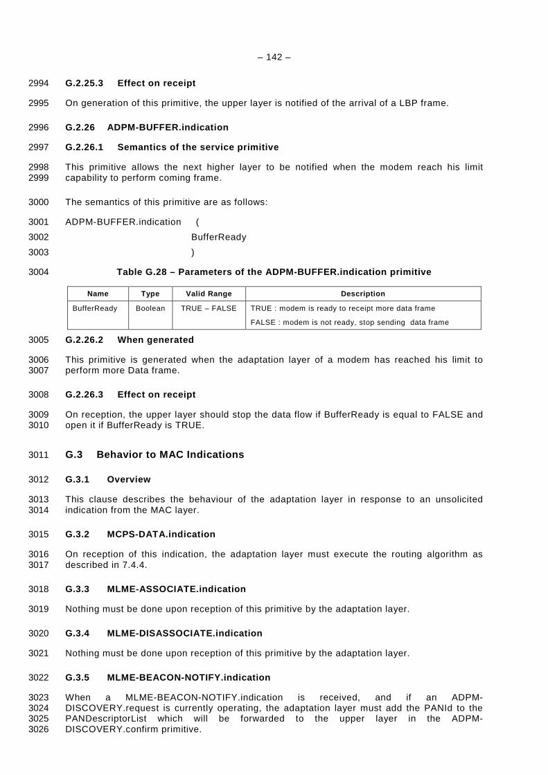
– 142 –
G.2.25.3 Effect on receipt 2994
On generation of this primitive, the upper layer is notified of the arrival of a LBP frame. 2995
G.2.26 ADPM-BUFFER.indication 2996
G.2.26.1 Semantics of the service primitive 2997
This primitive allows the next higher layer to be notified when the modem reach his limit 2998 capability to perform coming frame. 2999
The semantics of this primitive are as follows: 3000
ADPM-BUFFER.indication ( 3001
BufferReady 3002
) 3003
Table G.28 – Parameters of the ADPM-BUFFER.indicati on primitive 3004
Name Type Valid Range Description
BufferReady Boolean TRUE – FALSE TRUE : modem is ready to receipt more data frame
FALSE : modem is not ready, stop sending data frame
G.2.26.2 When generated 3005
This primitive is generated when the adaptation layer of a modem has reached his limit to 3006 perform more Data frame. 3007
G.2.26.3 Effect on receipt 3008
On reception, the upper layer should stop the data flow if BufferReady is equal to FALSE and 3009 open it if BufferReady is TRUE. 3010
G.3 Behavior to MAC Indications 3011
G.3.1 Overview 3012
This clause describes the behaviour of the adaptation layer in response to an unsolicited 3013 indication from the MAC layer. 3014
G.3.2 MCPS-DATA.indication 3015
On reception of this indication, the adaptation layer must execute the routing algorithm as 3016 described in 7.4.4. 3017
G.3.3 MLME-ASSOCIATE.indication 3018
Nothing must be done upon reception of this primitive by the adaptation layer. 3019
G.3.4 MLME-DISASSOCIATE.indication 3020
Nothing must be done upon reception of this primitive by the adaptation layer. 3021
G.3.5 MLME-BEACON-NOTIFY.indication 3022
When a MLME-BEACON-NOTIFY.indication is received, and if an ADPM-3023 DISCOVERY.request is currently operating, the adaptation layer must add the PANId to the 3024 PANDescriptorList which will be forwarded to the upper layer in the ADPM-3025 DISCOVERY.confirm primitive. 3026

– 143 –
G.3.6 MLME-GTS.indication 3027
Nothing must be done upon reception of this primitive by the adaptation layer. 3028
G.3.7 MLME-ORPHAN.indication 3029
Nothing must be done upon reception of this primitive by the adaptation layer. 3030
G.3.8 MLME-COMM-STATUS.indication 3031
On reception of this primitive, the adaptation layer must generate an ADPM-NETWORK-3032 STATUS.indication primitive, with the Status parameter equal to that of the MLME-COMM-3033 STATUS.indication primitive, and the AdditionalInformation parameter equal to the 3034 concatenation of the SrcAddr and DstAddr, separated by a “:”. 3035
G.3.9 MLME-SYNC-LOSS.indication 3036
Nothing must be done upon reception of this primitive by the adaptation layer. 3037
– 144 –
Annex H 3038 (normative) 3039
3040 Device Starting Sequence of messages 3041
Each device should start on Not_Device_Server status and then the following procedure is 3042 performed: 3043
a) Reset the equipment by sending the ADPM-RESET.request; 3044 b) Set the type of the device to switch it on Device or Server mode and optionally set the PIB 3045
parameters to configure it; 3046
– If the equipment is a device it should perform: 3047
c) Discovery procedure by invoking the ADPM-NETWORK-DISCOVERY.request; 3048
d) If there is a device or a server in its pose, it must then invoke the ADPM-NETWORK-3049 JOINNING.request to perform the bootstrapping procedure; 3050
– Else (the equipment is a server) it should perform: 3051
e) Discovery procedure by invoking the ADPM-NETWORK-DISCOVERY.request. 3052
f) If there is a device in the server’s pose, it should invoke the ADPM-NETWORK-START; 3053 else it switches to joining status. 3054
Equipment can’t send or receive data or load packet unless it is joined. 3055