Embed Size (px)
Citation preview
Experience Seminar - 1
1. Start InRoads
1-1. Start InRoads
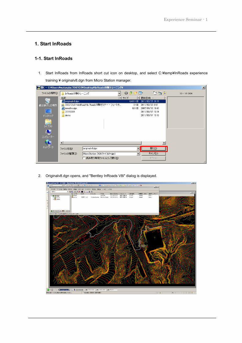
1. Start InRoads from InRoads short cut icon on desktop, and select C:¥temp¥InRoads experience
training ¥ originalv8.dgn from Micro Station manager.
2. Originalv8.dgn opens, and "Bentley InRoads V8i" dialog is displayed.
Experience Seminar -2
2. Import terrain surface for InRoads training
2-1. Import terrain surface for InRoads training
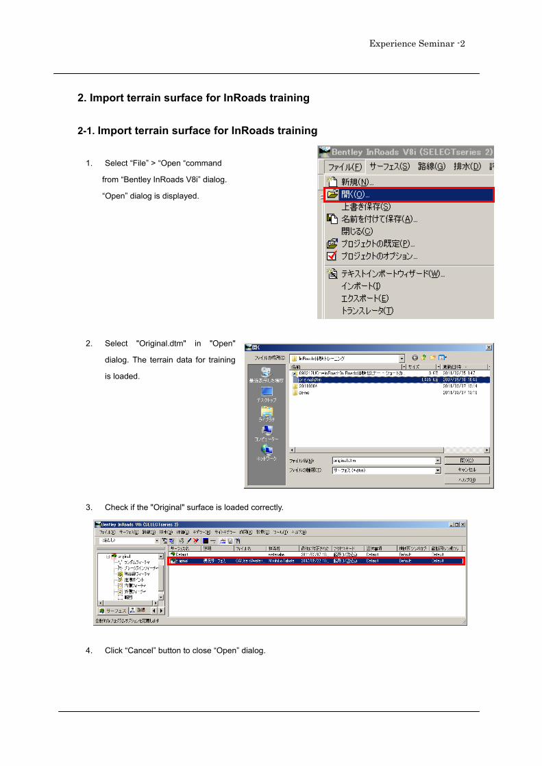
1. Select “File” > “Open “command
from “Bentley InRoads V8i” dialog.
“Open” dialog is displayed.
2. Select "Original.dtm" in "Open"
dialog. The terrain data for training
is loaded.
3. Check if the "Original" surface is loaded correctly.
4. Click “Cancel” button to close “Open” dialog.
Experience Seminar - 3
3. Display triangular surface
3-1.Display triangular surface
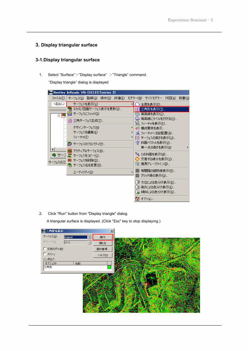
1. Select “Surface”>”Display surface” >”Triangle” command.
“Display triangle” dialog is displayed
2. Click "Run" button from "Display triangle" dialog.
A triangular surface is displayed. (Click "Esc" key to stop displaying.)
Experience Seminar -4
4. Design route on road
4-1. Define the horizontal route shape
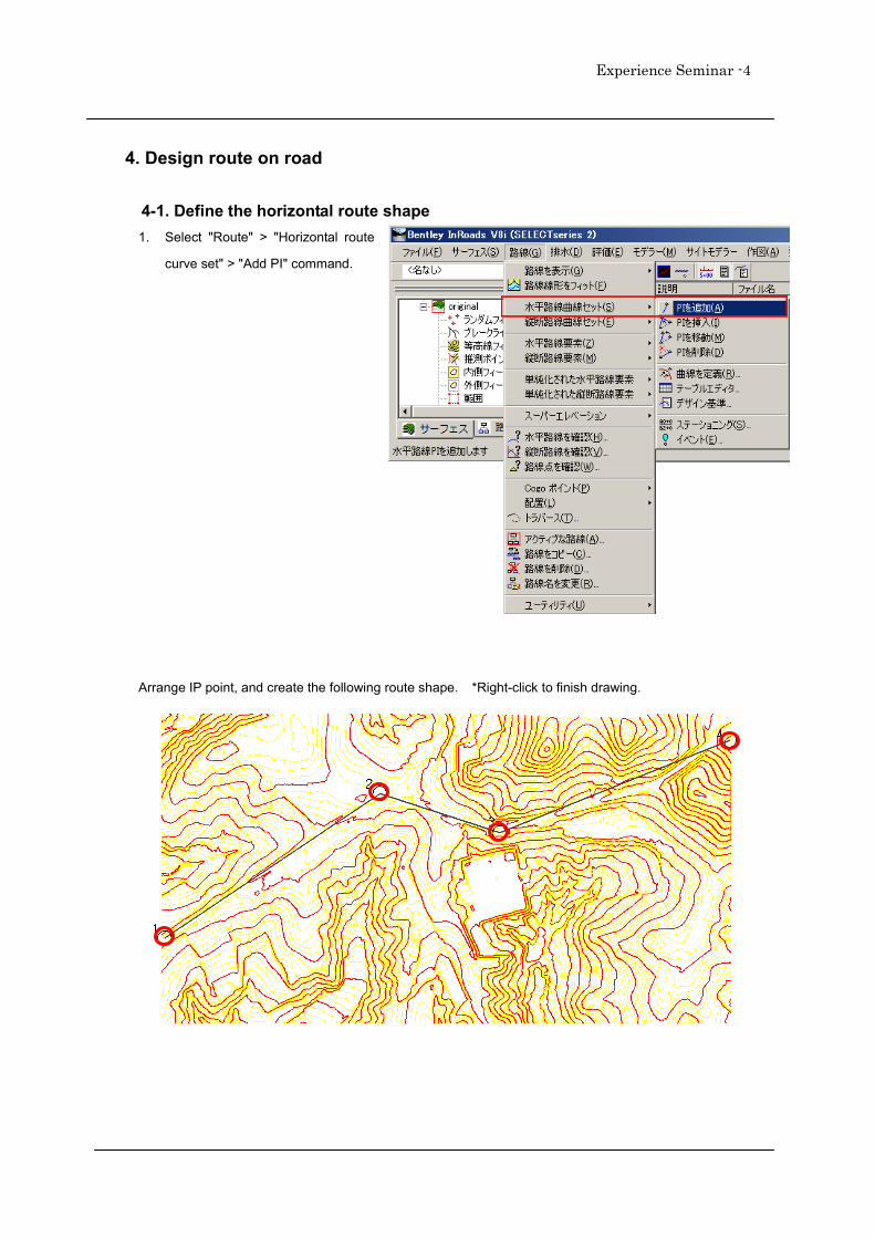
1. Select "Route" > "Horizontal route
curve set" > "Add PI" command.
Arrange IP point, and create the following route shape. *Right-click to finish drawing.
Experience Seminar - 5
4-2.Define curve clothoid of the horizontal route shape
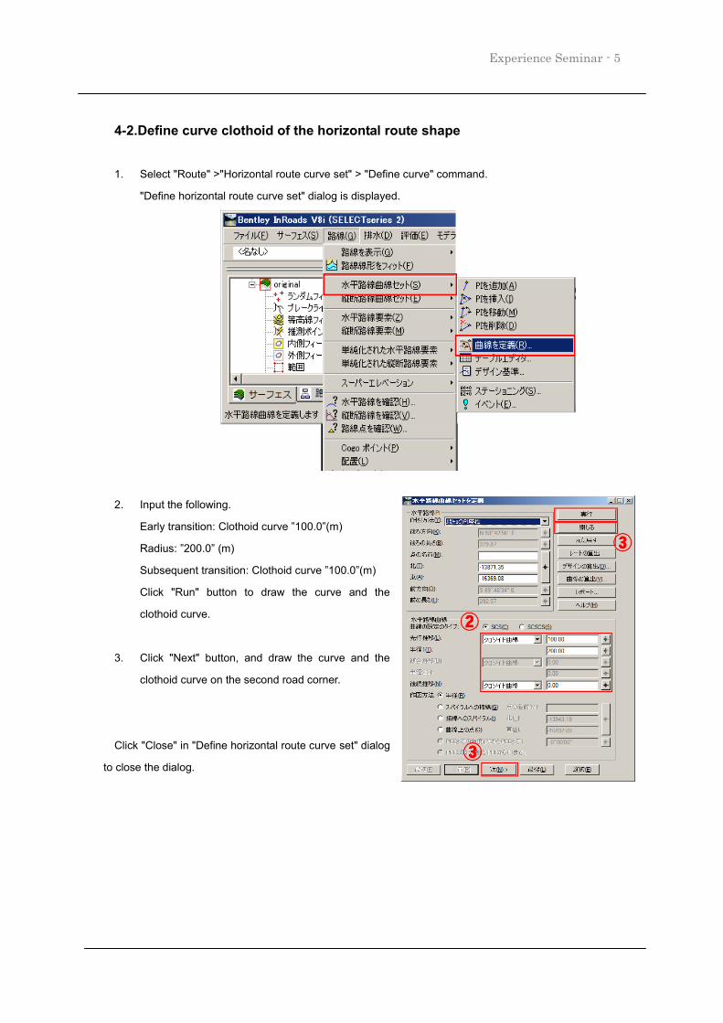
1. Select "Route" >"Horizontal route curve set" > "Define curve" command.
"Define horizontal route curve set" dialog is displayed.
2. Input the following.
Early transition: Clothoid curve ”100.0”(m)
Radius: ”200.0” (m)
Subsequent transition: Clothoid curve ”100.0”(m)
Click "Run" button to draw the curve and the
clothoid curve.
3. Click "Next" button, and draw the curve and the
clothoid curve on the second road corner.
Click "Close" in "Define horizontal route curve set" dialog
to close the dialog.
Experience Seminar -6
4-3. Create vertical section for vertical planning line
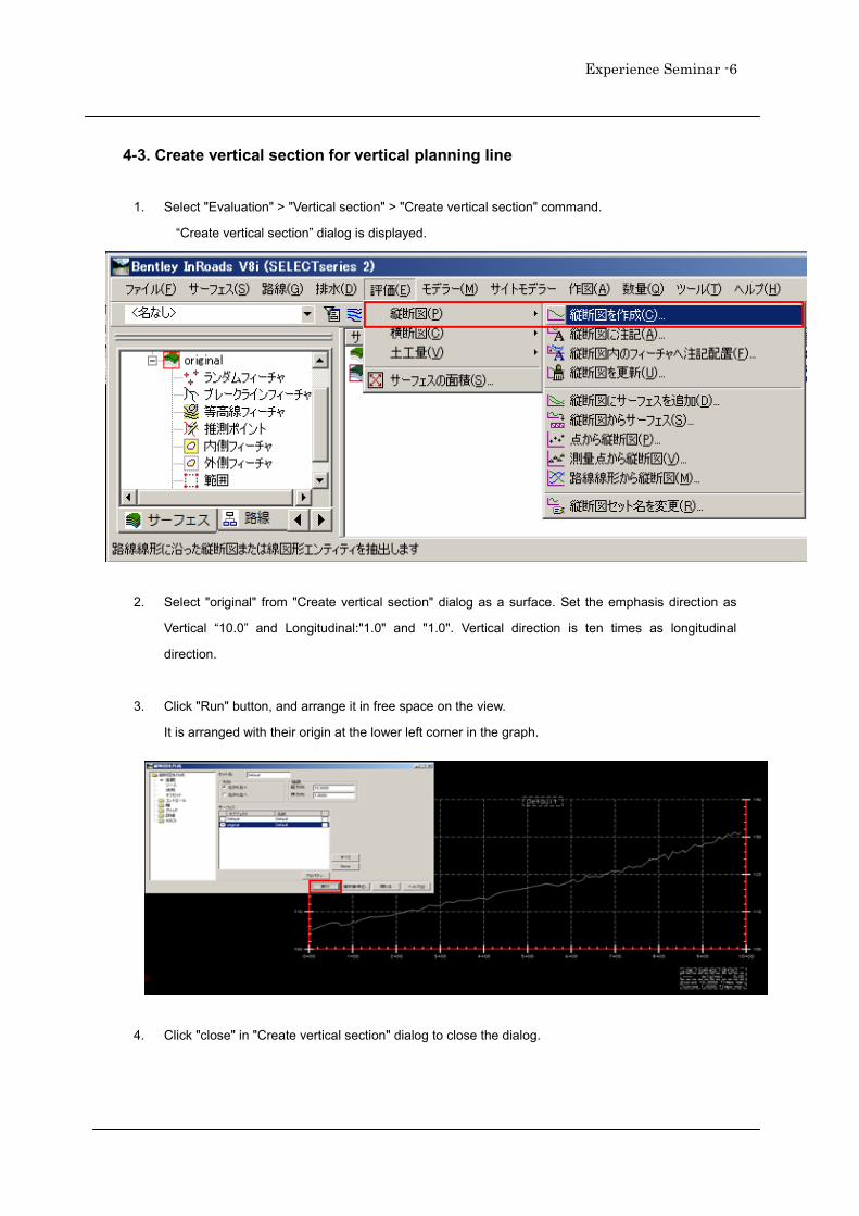
1. Select "Evaluation" > "Vertical section" > "Create vertical section" command.
“Create vertical section” dialog is displayed.
2. Select "original" from "Create vertical section" dialog as a surface. Set the emphasis direction as
Vertical “10.0” and Longitudinal:"1.0" and "1.0". Vertical direction is ten times as longitudinal
direction.
3. Click "Run" button, and arrange it in free space on the view.
It is arranged with their origin at the lower left corner in the graph.
4. Click "close" in "Create vertical section" dialog to close the dialog.
Experience Seminar - 7
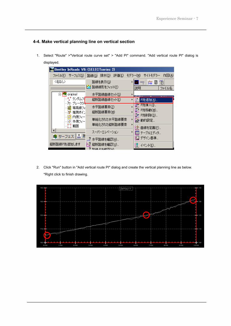
4-4. Make vertical planning line on vertical section
1. Select "Route" >"Vertical route curve set" > "Add PI" command. "Add vertical route PI" dialog is
displayed.
2. Click "Run" button in "Add vertical route PI" dialog and create the vertical planning line as below.
*Right click to finish drawing.
Experience Seminar -8
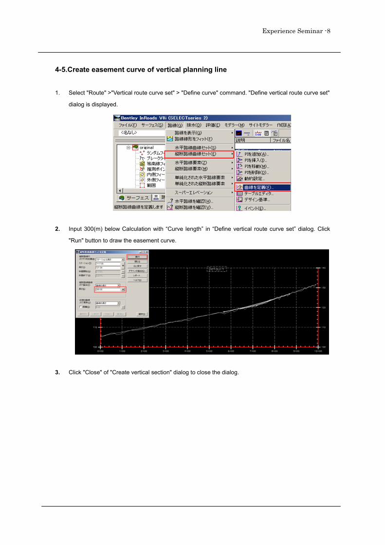
4-5.Create easement curve of vertical planning line
1. Select "Route" >"Vertical route curve set" > "Define curve" command. "Define vertical route curve set"
dialog is displayed.
2. Input 300(m) below Calculation with “Curve length” in “Define vertical route curve set” dialog. Click
"Run" button to draw the easement curve.
3. Click "Close" of "Create vertical section" dialog to close the dialog.
Experience Seminar - 9
5.Create road with roadway designer
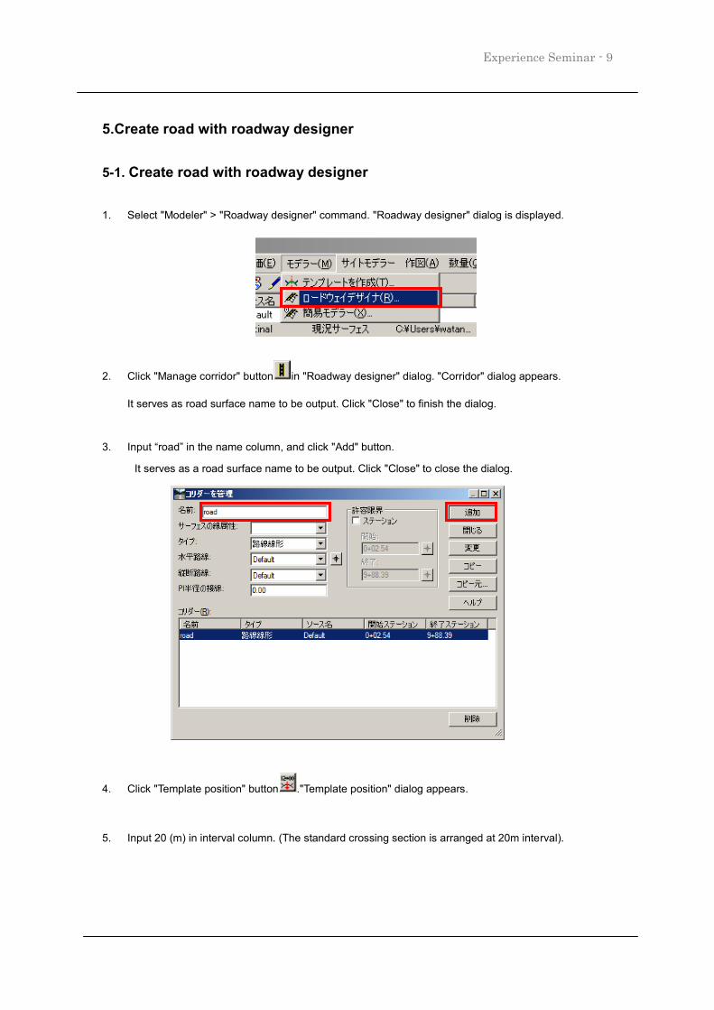
5-1. Create road with roadway designer
1. Select "Modeler" > "Roadway designer" command. "Roadway designer" dialog is displayed.
2. Click "Manage corridor" button in "Roadway designer" dialog. "Corridor" dialog appears.
It serves as road surface name to be output. Click "Close" to finish the dialog.
3. Input “road” in the name column, and click "Add" button.
It serves as a road surface name to be output. Click "Close" to close the dialog.
4. Click "Template position" button ."Template position" dialog appears.
5. Input 20 (m) in interval column. (The standard crossing section is arranged at 20m interval).
Experience Seminar -10
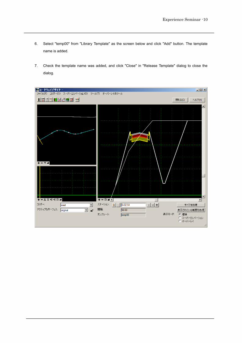
6. Select "temp00" from "Library Template" as the screen below and click "Add" button. The template
name is added.
7. Check the template name was added, and click "Close" in "Release Template" dialog to close the
dialog.
Experience Seminar - 11
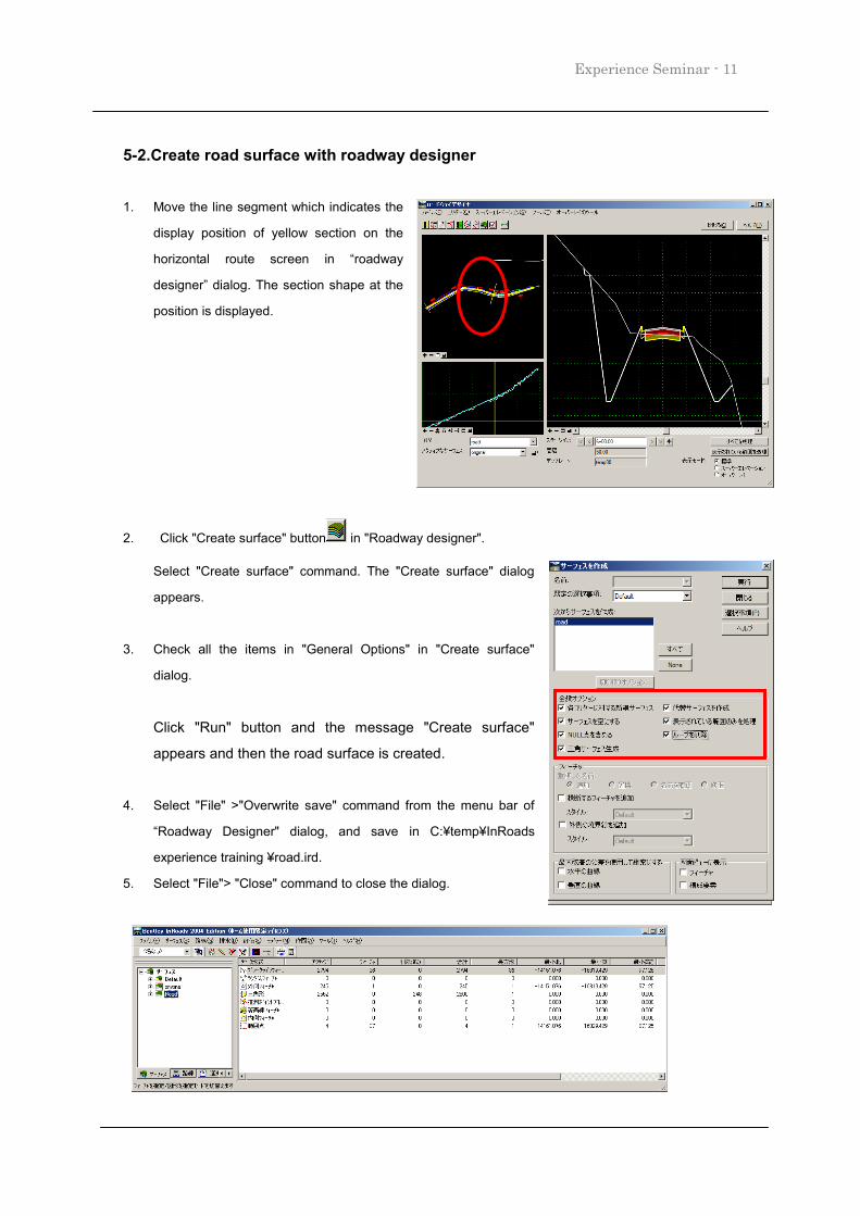
5-2.Create road surface with roadway designer
1. Move the line segment which indicates the
display position of yellow section on the
horizontal route screen in “roadway
designer” dialog. The section shape at the
position is displayed.
2. Click "Create surface" button in "Roadway designer".
Select "Create surface" command. The "Create surface" dialog
appears.
3. Check all the items in "General Options" in "Create surface"
dialog.
Click "Run" button and the message "Create surface"
appears and then the road surface is created.
4. Select "File" >"Overwrite save" command from the menu bar of
“Roadway Designer" dialog, and save in C:¥temp¥InRoads
experience training ¥road.ird.
5. Select "File"> "Close" command to close the dialog.
Experience Seminar -12
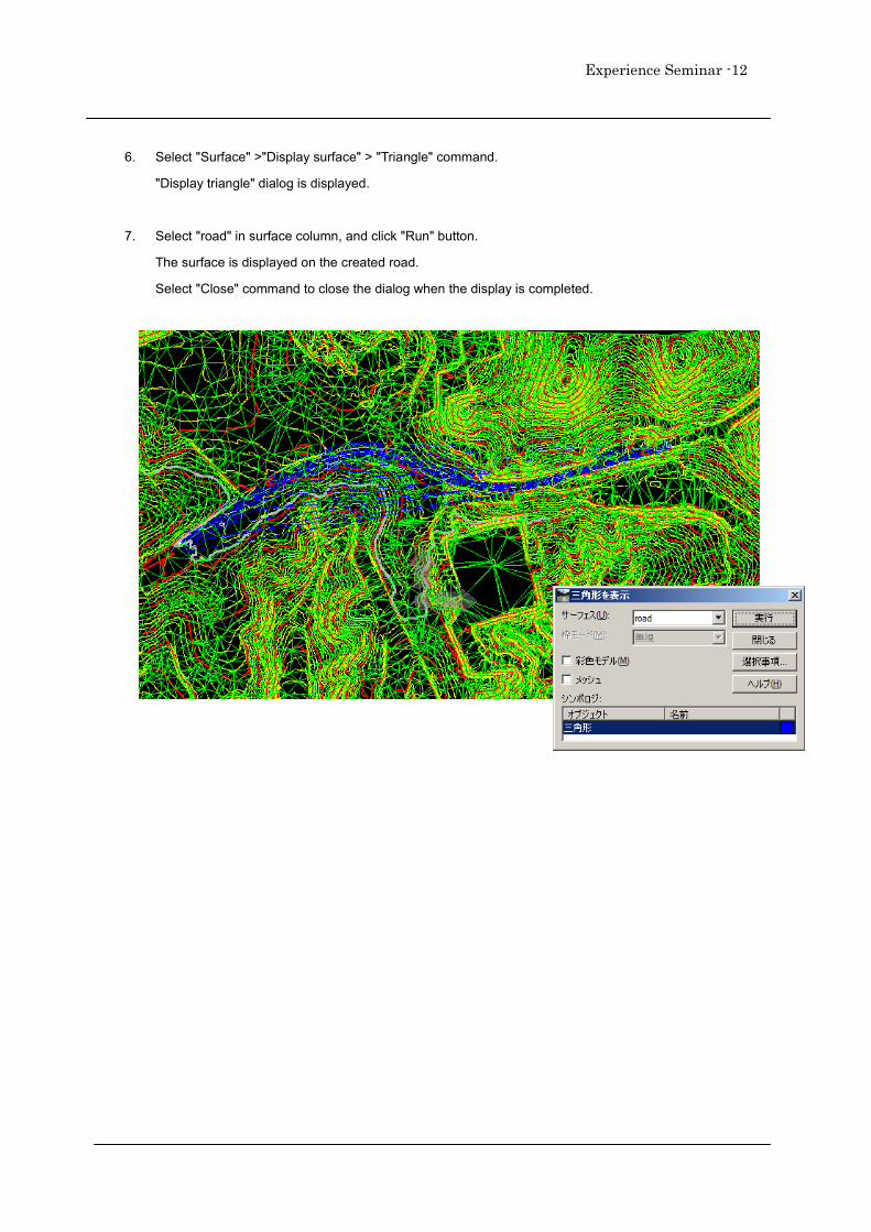
6. Select "Surface" >"Display surface" > "Triangle" command.
"Display triangle" dialog is displayed.
7. Select "road" in surface column, and click "Run" button.
The surface is displayed on the created road.
Select "Close" command to close the dialog when the display is completed.
Experience Seminar - 13
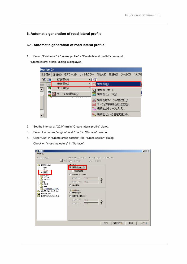
6. Automatic generation of road lateral profile
6-1. Automatic generation of road lateral profile
1. Select "Evaluation" >"Lateral profile" > "Create lateral profile" command.
"Create lateral profile” dialog is displayed.
2. Set the interval at "20.0" (m) in "Create lateral profile" dialog.
3. Select the current "original" and "road" in "Surface" column.
4. Click "Use" in "Create cross section" tree, "Cross section" dialog.
Check on "crossing feature" in "Surface".
Experience Seminar -14
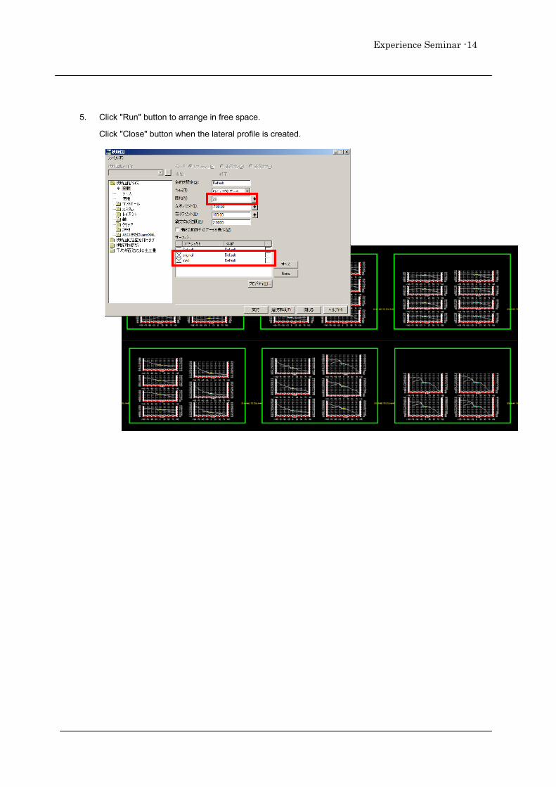
5. Click "Run" button to arrange in free space.
Click "Close" button when the lateral profile is created.
Experience Seminar - 15
7. Export to LandXML
7-1. Export surface (terrain) and route data
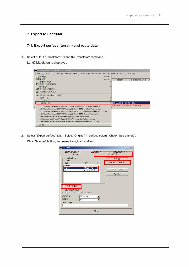
1. Select "File" >"Translator" > "LandXML translator" command.
LandXML dialog is displayed.
2. Select "Export surface" tab. Select “Original” in surface column.Check “Use triangle”.
Click “Save as” button, and name it originarl_surf.xml.
Experience Seminar -16
7-2. Export route type data
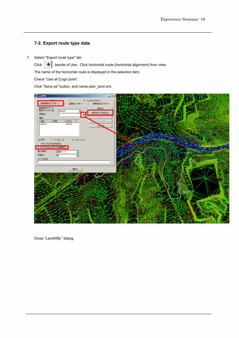
1. Select "Export route type" tab.
Click beside of Use:. Click horizontal route (horizontal alignment) from view.
The name of the horizontal route is displayed in the selection item.
Check “Use all Cogo point”.
Click "Save as" button, and name plan_land.xml.
Close "LandXML" dialog.
Experience Seminar - 17
7-2. Export road section (lateral profile)
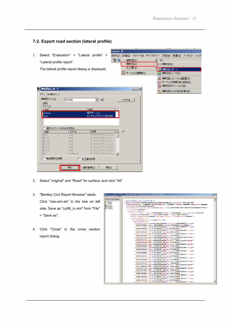
1. Select "Evaluation” > “Lateral profile” >
“Lateral profile report”.
The lateral profile report dialog is displayed.
2. Select "original" and "Road" for surface, and click "All"
3. "Bentley Civil Report Browser" starts.
Click "raw-xml.xls" in the tree on left
side. Save as "cutfill_in.xml" from "File"
> "Save as".
4. Click "Close" in the cross section
report dialog.
Experience Seminar -18
8. Import from LandXML
8-1.Open new file
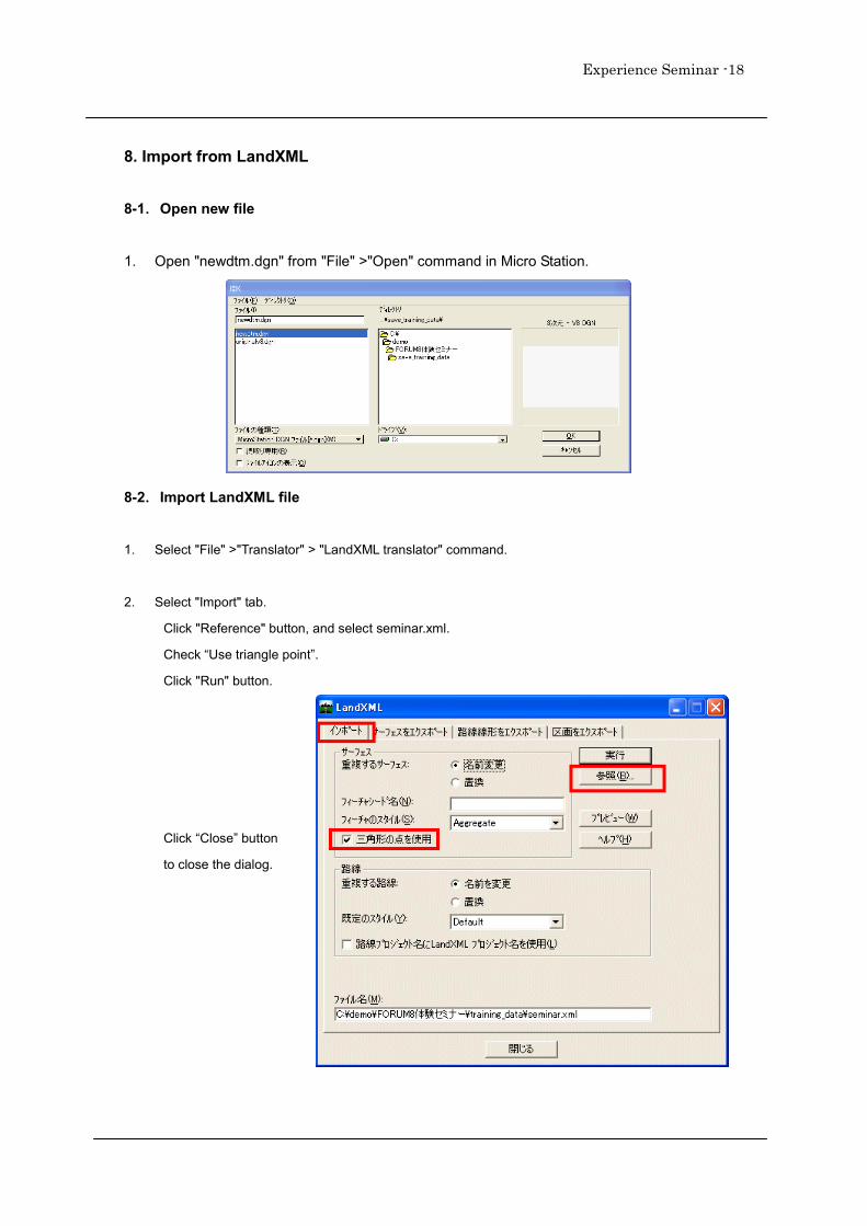
1. Open "newdtm.dgn" from "File" >"Open" command in Micro Station.
8-2.Import LandXML file
1. Select "File" >"Translator" > "LandXML translator" command.
2. Select "Import" tab.
Click "Reference" button, and select seminar.xml.
Check “Use triangle point”.
Click "Run" button.
Click “Close” button
to close the dialog.
Experience Seminar - 19
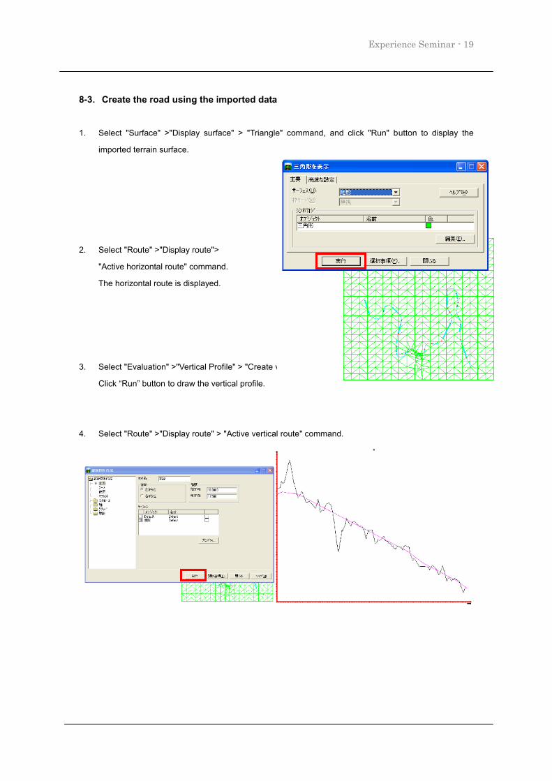
8-3.Create the road using the imported data
1. Select "Surface" >"Display surface" > "Triangle" command, and click "Run" button to display the
imported terrain surface.
2. Select "Route" >"Display route">
"Active horizontal route" command.
The horizontal route is displayed.
3. Select "Evaluation" >"Vertical Profile" > "Create vertical profile" command.
Click “Run” button to draw the vertical profile.
4. Select "Route" >"Display route" > "Active vertical route" command.
Experience Seminar -20
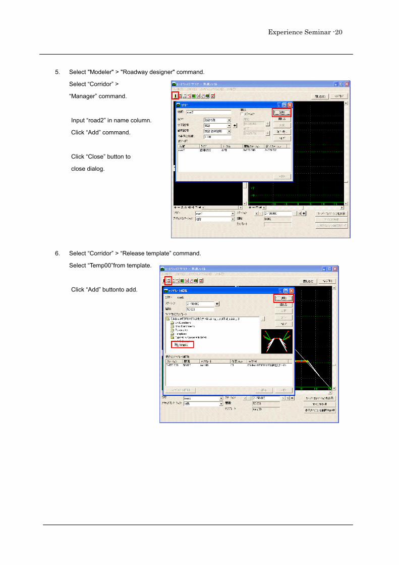
5. Select "Modeler" > "Roadway designer" command.
Select “Corridor” >
“Manager” command.
Input “road2” in name column.
Click “Add” command.
Click “Close” button to
close dialog.
6. Select “Corridor” > “Release template” command.
Select “Temp00”from template.
Click “Add” buttonto add.
Experience Seminar - 21
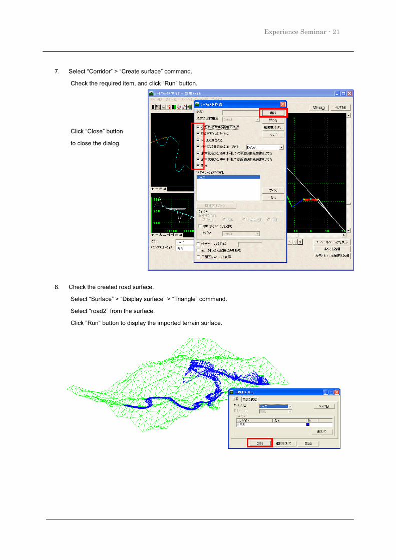
7. Select “Corridor” > “Create surface” command.
Check the required item, and click “Run” button.
Click “Close” button
to close the dialog.
8. Check the created road surface.
Select “Surface” > “Display surface” > “Triangle” command.
Select “road2” from the surface.
Click "Run" button to display the imported terrain surface.


![PostgreSQL - repositorio.siu.edu.ar · . Ejemplos ... postgres=# \h create function... CREATE [ OR REPLACE ] FUNCTION](https://img.pdfslide.tips/doc/110x75/5bf9fecb09d3f2712b8b9116/postgresql-ejemplos-postgres-h-create-function-create-or-replace.jpg)