Embed Size (px)
Citation preview
LEG ProjectP A U L S C H E R R E R I N S T I T U T
Simon C. Leemann, May 3 2004 1
100keV Gun Test StandDesign and Parameter Study
Internal Note SLS-TME-TA-2004-0244http://slsbd.psi.ch/pub/slsnotes/

Simon C. Leemann, May 3 2004 2
P A U L S C H E R R E R I N S T I T U T LEG Project
Topics
• Gun Geometries
• Parameter Studies
• Solenoid Field
• Diode Gap
• Bunch Charge
• Bunch Length
• Active Emitter Area
• Scaling Laws and Extrapolation
• Projected Emittance and Slice Emittance
• Conclusions
Simon C. Leemann, May 3 2004 3
P A U L S C H E R R E R I N S T I T U T LEG Project
• Gun Geometries
• Parameter Studies
• Solenoid Field
• Diode Gap
• Bunch Charge
• Bunch Length
• Active Emitter Area
• Scaling Laws Extrapolation
• Projected Emittance and Slice Emittance
• Conclusions
Topics
Simon C. Leemann, May 3 2004 4
P A U L S C H E R R E R I N S T I T U T LEG Project
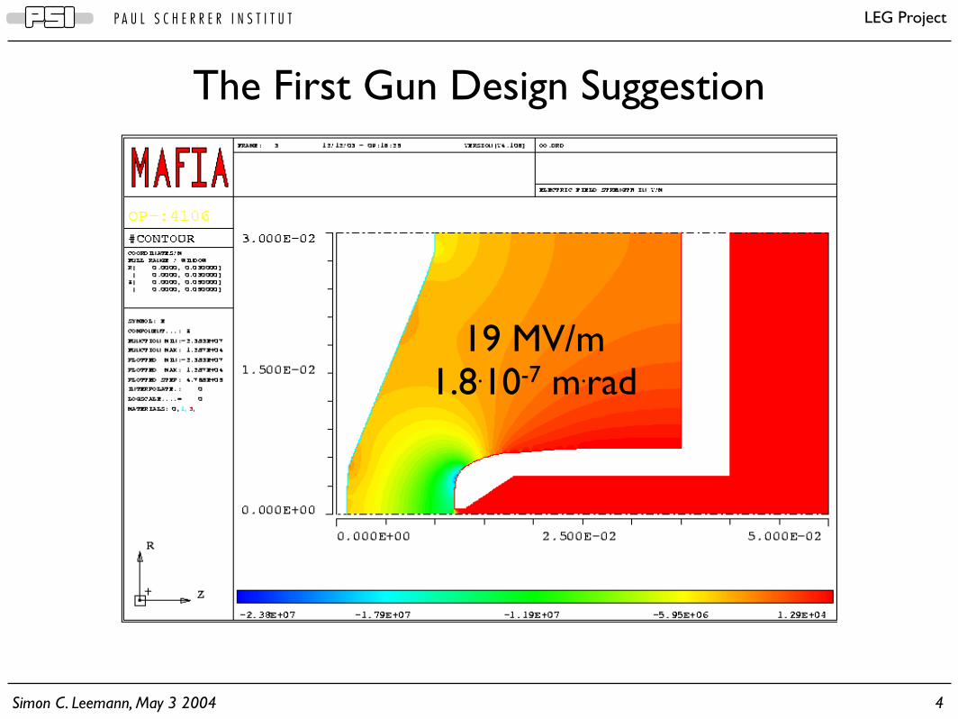
The First Gun Design Suggestion
19 MV/m1.8.10-7 m.rad
Simon C. Leemann, May 3 2004 5
P A U L S C H E R R E R I N S T I T U T LEG Project
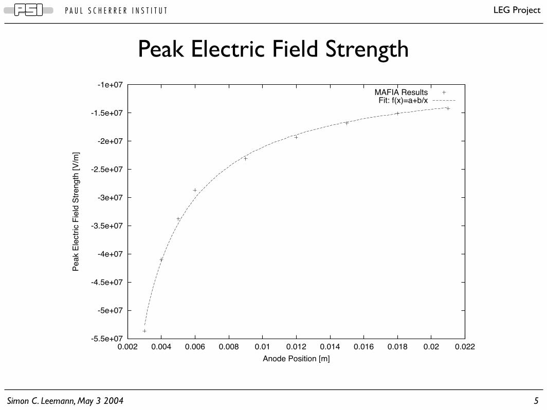
Peak Electric Field Strength
-5.5e+07
-5e+07
-4.5e+07
-4e+07
-3.5e+07
-3e+07
-2.5e+07
-2e+07
-1.5e+07
-1e+07
0.002 0.004 0.006 0.008 0.01 0.012 0.014 0.016 0.018 0.02 0.022
Pe
ak E
lectr
ic F
ield
Str
en
gth
[V
/m]
Anode Position [m]
MAFIA ResultsFit: f(x)=a+b/x
Simon C. Leemann, May 3 2004 6
P A U L S C H E R R E R I N S T I T U T LEG Project
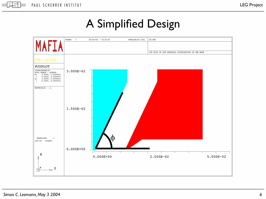
A Simplified Design
MATERIALS: 1,3,
!
0.000E+00 5.000E!022.500E!02
0.000E+00
3.000E!02
1.500E!02
FRAME: 1 20/04/04 ! 16:34:01 VERSION[V4.106] OO.DRD
CUT PLOT OF THE MATERIAL DISTRIBUTION IN THE MESH
OM!:4106
COORDINATES/M
FULL RANGE / WINDOW
R[ 0.0000, 0.030000]
[ 0.0000, 0.030000]
Z[ 0.0000, 0.050000]
[ 0.0000, 0.050000]
#2DPLOT
!MESHLINE= 1
CUT AT =CONST.
Z
R
+
Simon C. Leemann, May 3 2004 7
P A U L S C H E R R E R I N S T I T U T LEG Project
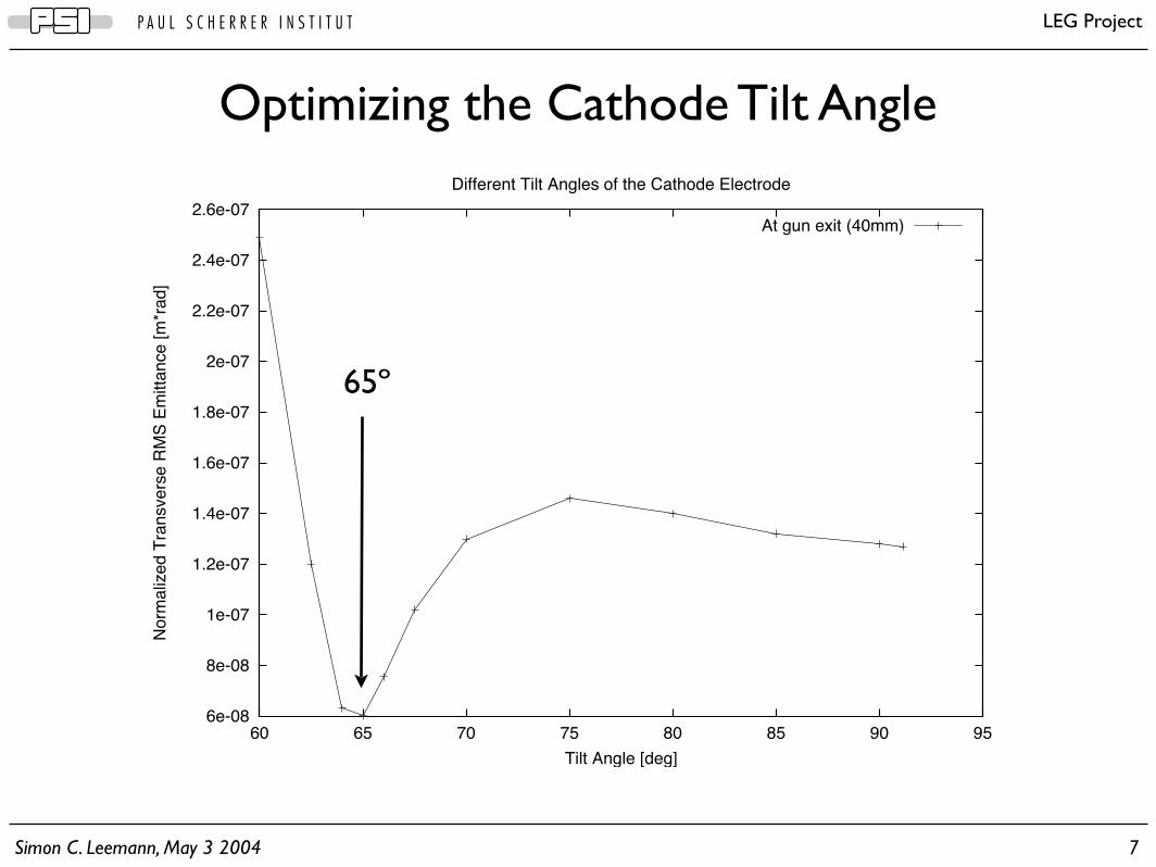
Optimizing the Cathode Tilt Angle
6e-08
8e-08
1e-07
1.2e-07
1.4e-07
1.6e-07
1.8e-07
2e-07
2.2e-07
2.4e-07
2.6e-07
60 65 70 75 80 85 90 95
No
rma
lize
d T
ran
sve
rse
RM
S E
mitta
nce
[m
*ra
d]
Tilt Angle [deg]
Different Tilt Angles of the Cathode Electrode
At gun exit (40mm)
65º
Simon C. Leemann, May 3 2004 8
P A U L S C H E R R E R I N S T I T U T LEG Project
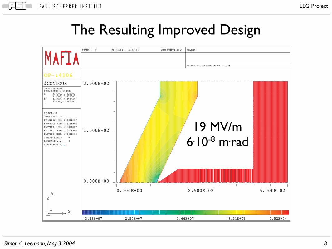
0.000E+00 5.000E-022.500E-02
0.000E+00
3.000E-02
1.500E-02
FRAME: 3 20/04/04 - 16:34:01 VERSION[V4.106] OO.DRD
ELECTRIC FIELD STRENGTH IN V/M
OP-:4106
COORDINATES/MFULL RANGE / WINDOWR[ 0.0000, 0.030000] [ 0.0000, 0.030000]Z[ 0.0000, 0.050000] [ 0.0000, 0.050000]
#CONTOUR
SYMBOL: E
COMPONENT...: Z
FUNCTION MIN:-3.330E+07
FUNCTION MAX: 1.515E+04
PLOTTED MIN:-3.330E+07
PLOTTED MAX: 1.515E+04
PLOTTED STEP: 6.662E+05
INTERPOLATE.: 0
LOGSCALE....= 0
MATERIALS: 0,1,3,
Z
R
+
-3.33E+07 -2.50E+07 -1.66E+07 -8.31E+06 1.52E+04
The Resulting Improved Design
19 MV/m6.10-8 m.rad

Simon C. Leemann, May 3 2004 9
P A U L S C H E R R E R I N S T I T U T LEG Project
• Gun Geometries
• Parameter Studies
• Solenoid Field
• Diode Gap
• Bunch Charge
• Bunch Length
• Active Emitter Area
• Scaling Laws and Extrapolation
• Projected Emittance and Slice Emittance
• Conclusions
Topics
Simon C. Leemann, May 3 2004 10
P A U L S C H E R R E R I N S T I T U T LEG Project
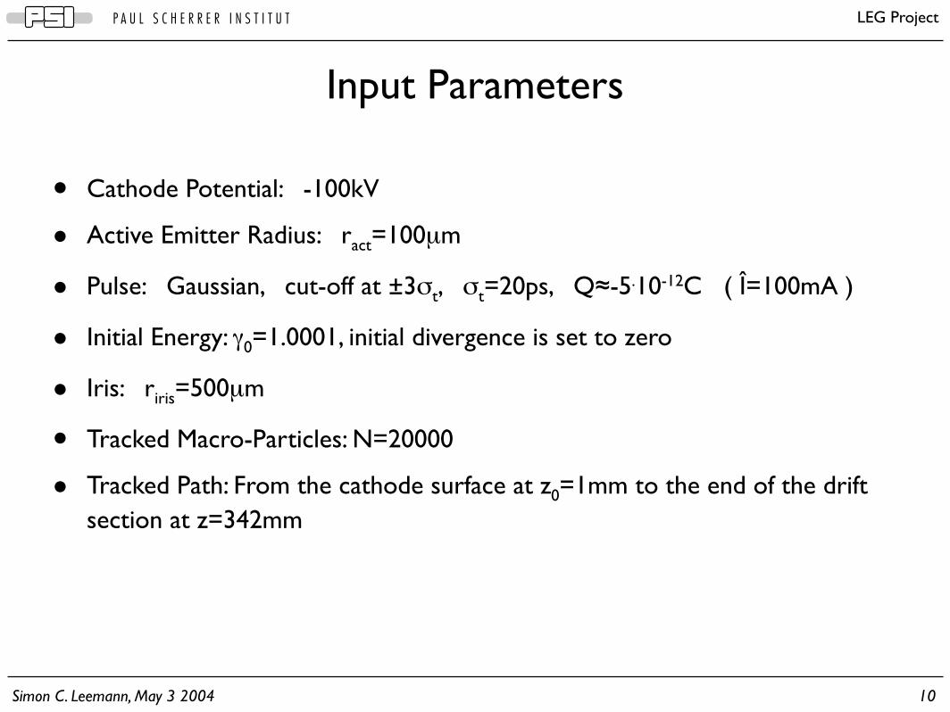
• Cathode Potential: -100kV
• Active Emitter Radius: ract=100µm
• Pulse: Gaussian, cut-off at ±3σt, σt=20ps, Q≈-5.10-12C ( Î=100mA )
• Initial Energy: γ0=1.0001, initial divergence is set to zero
• Iris: riris=500µm
• Tracked Macro-Particles: N=20000
• Tracked Path: From the cathode surface at z0=1mm to the end of the drift section at z=342mm
Input Parameters

Simon C. Leemann, May 3 2004 11
P A U L S C H E R R E R I N S T I T U T LEG Project
Input Geometry
MATERIALS: 1,3,21,22,
0.000E+00 7.000E-023.500E-02
0.000E+00
3.000E-02
1.500E-02
FRAME: 1 03/05/04 - 15:37:14 VERSION[V4.106] OO.DRD
CUT PLOT OF THE MATERIAL DISTRIBUTION IN THE MESH
OM-:4106
COORDINATES/MFULL RANGE / WINDOWR[ 0.0000, 0.030000] [ 0.0000, 0.030000]Z[ 0.0000, 0.070000] [ 0.0000, 0.070000]
#2DPLOT
-MESHLINE= 1
CUT AT =CONST.
Z
R
+

Simon C. Leemann, May 3 2004 12
P A U L S C H E R R E R I N S T I T U T LEG Project
• Gun Geometries
• Parameter Studies
• Solenoid Field
• Diode Gap
• Bunch Charge
• Bunch Length
• Active Emitter Area
• Scaling Laws and Extrapolation
• Projected Emittance and Slice Emittance
• Conclusions
Topics

Simon C. Leemann, May 3 2004 13
P A U L S C H E R R E R I N S T I T U T LEG Project
Applying a Solenoid Field (1)
Simon C. Leemann, May 3 2004 14
P A U L S C H E R R E R I N S T I T U T LEG Project
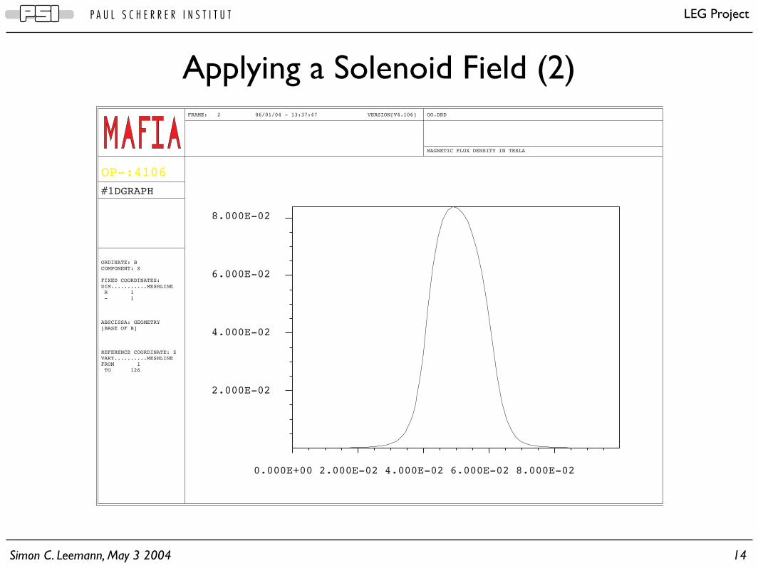
Applying a Solenoid Field (2)
2.000E-02
4.000E-02
6.000E-02
8.000E-02
0.000E+00 2.000E-02 4.000E-02 6.000E-02 8.000E-02
FRAME: 2 06/01/04 - 13:37:47 VERSION[V4.106] OO.DRD
MAGNETIC FLUX DENSITY IN TESLA
OP-:4106
#1DGRAPH
ORDINATE: BCOMPONENT: Z
FIXED COORDINATES:DIM...........MESHLINE R 1 - 1
ABSCISSA: GEOMETRY[BASE OF B]
REFERENCE COORDINATE: ZVARY..........MESHLINEFROM 1 TO 126
Simon C. Leemann, May 3 2004 15
P A U L S C H E R R E R I N S T I T U T LEG Project
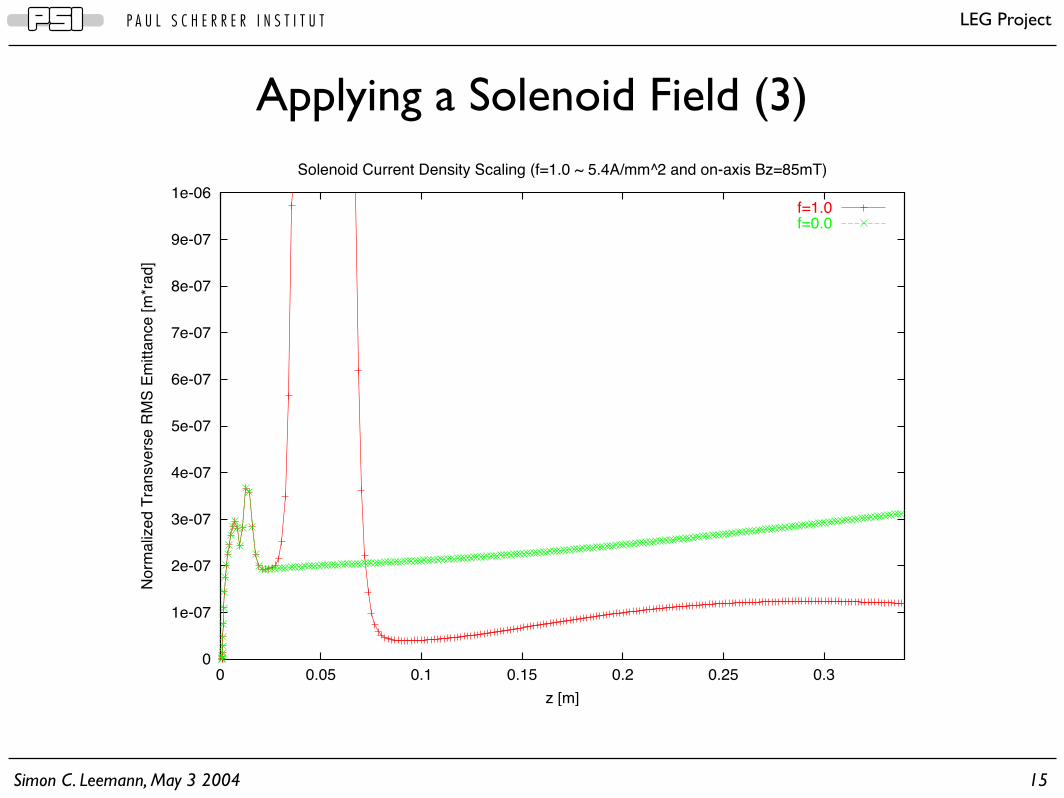
Applying a Solenoid Field (3)
0
1e-07
2e-07
3e-07
4e-07
5e-07
6e-07
7e-07
8e-07
9e-07
1e-06
0 0.05 0.1 0.15 0.2 0.25 0.3
No
rma
lize
d T
ran
sve
rse
RM
S E
mitta
nce
[m
*ra
d]
z [m]
Solenoid Current Density Scaling (f=1.0 ~ 5.4A/mm^2 and on-axis Bz=85mT)
f=1.0f=0.0
Simon C. Leemann, May 3 2004 16
P A U L S C H E R R E R I N S T I T U T LEG Project
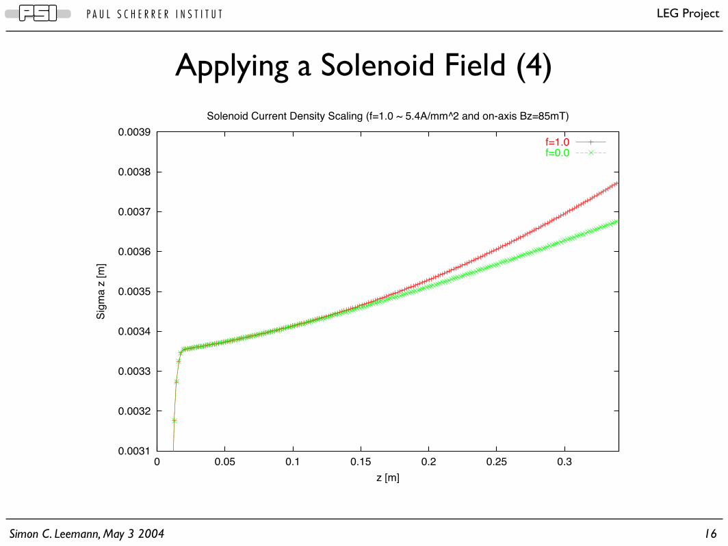
Applying a Solenoid Field (4)
0.0031
0.0032
0.0033
0.0034
0.0035
0.0036
0.0037
0.0038
0.0039
0 0.05 0.1 0.15 0.2 0.25 0.3
Sig
ma
z [
m]
z [m]
Solenoid Current Density Scaling (f=1.0 ~ 5.4A/mm^2 and on-axis Bz=85mT)
f=1.0f=0.0
Simon C. Leemann, May 3 2004 17
P A U L S C H E R R E R I N S T I T U T LEG Project
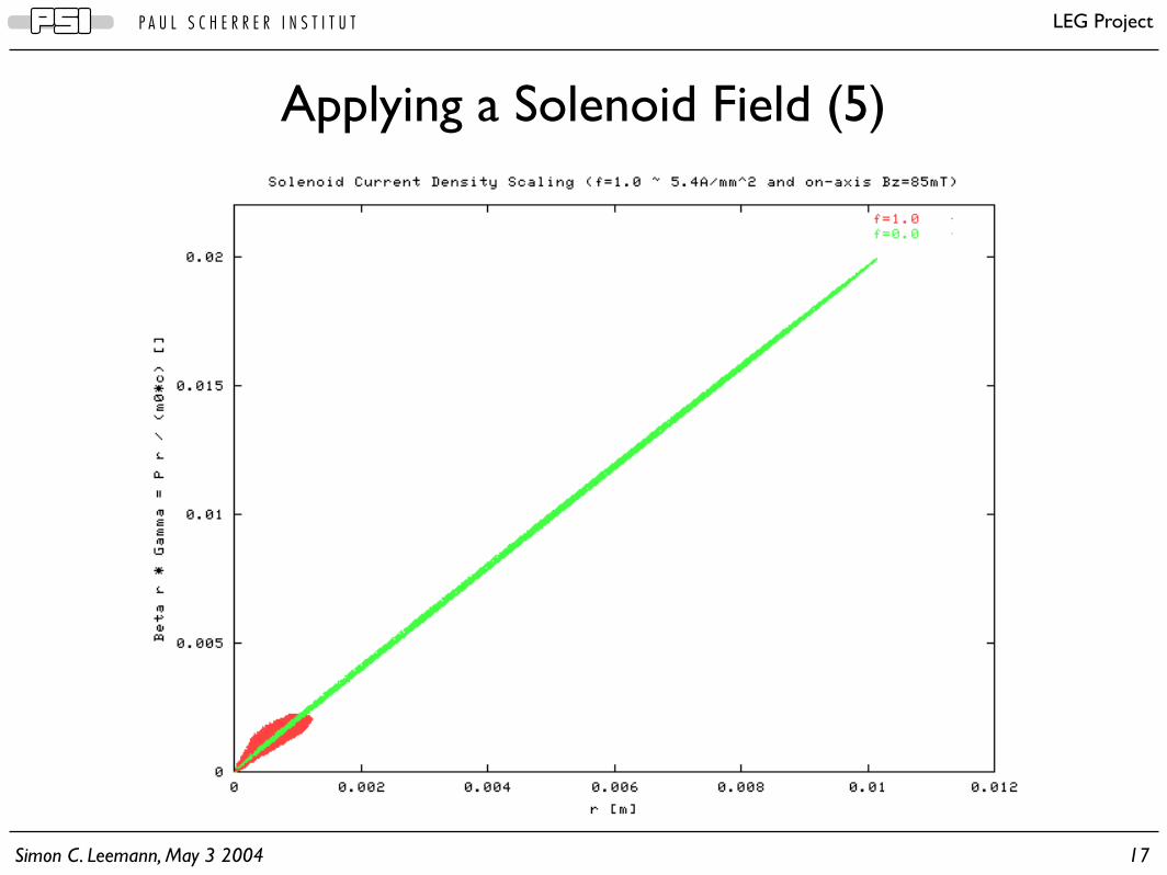
Applying a Solenoid Field (5)
Simon C. Leemann, May 3 2004 18
P A U L S C H E R R E R I N S T I T U T LEG Project
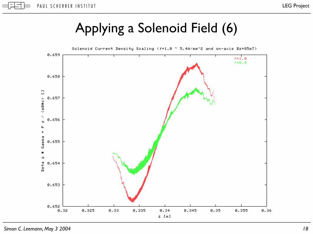
Applying a Solenoid Field (6)

Simon C. Leemann, May 3 2004 19
P A U L S C H E R R E R I N S T I T U T LEG Project
Applying a Solenoid Field (7)
2.4.10-8 m.rad
0
2e-07
4e-07
6e-07
8e-07
1e-06
1.2e-06
0 0.2 0.4 0.6 0.8 1 1.2 1.4 1.6 1.8
No
rma
lize
d T
ran
sve
rse
RM
S E
mitta
nce
[m
*ra
d]
Solenoid Current Density Scaling (1.0 ~ 5.4A/mm^2 and on-axis Bz=85mT)
At exit (34cm)
Simon C. Leemann, May 3 2004 20
P A U L S C H E R R E R I N S T I T U T LEG Project
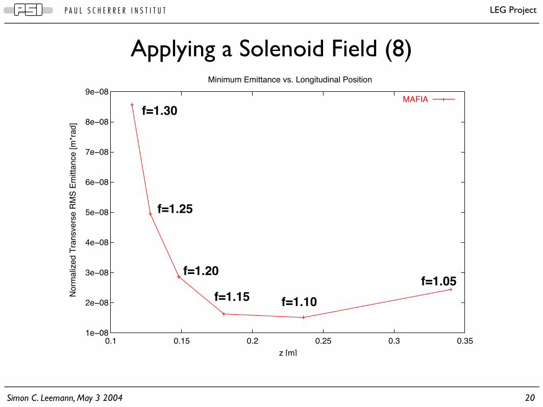
Applying a Solenoid Field (8)
1e!08
2e!08
3e!08
4e!08
5e!08
6e!08
7e!08
8e!08
9e!08
0.1 0.15 0.2 0.25 0.3 0.35
No
rma
lize
d T
ran
sve
rse
RM
S E
mitta
nce
[m
*ra
d]
z [m]
Minimum Emittance vs. Longitudinal Position
MAFIA
f=1.05
f=1.10f=1.15
f=1.20
f=1.25
f=1.30

Simon C. Leemann, May 3 2004 21
P A U L S C H E R R E R I N S T I T U T LEG Project
• Gun Geometries
• Parameter Studies
• Solenoid Field
• Diode Gap
• Bunch Charge
• Bunch Length
• Active Emitter Area
• Scaling Laws and Extrapolation
• Projected Emittance and Slice Emittance
• Conclusions
Topics

Simon C. Leemann, May 3 2004 22
P A U L S C H E R R E R I N S T I T U T LEG Project
Varying the Gap (1)
11mm gap

Simon C. Leemann, May 3 2004 23
P A U L S C H E R R E R I N S T I T U T LEG Project
Varying the Gap (2)
0
5e-08
1e-07
1.5e-07
2e-07
2.5e-07
3e-07
3.5e-07
4e-07
4 5 6 7 8 9 10 11
No
rma
lize
d T
ran
sve
rse
RM
S E
mitta
nce
[m
*ra
d]
Diode Gap [mm]
Diode Gap of 11mm Corresponds to 19MV/m Peak Field
30cm after anode tip, f=0.030cm after anode tip, f=0.530cm after anode tip, f=1.0
30cm after anode tip, f=1.05

Simon C. Leemann, May 3 2004 24
P A U L S C H E R R E R I N S T I T U T LEG Project
• Gun Geometries
• Parameter Studies
• Solenoid Field
• Diode Gap
• Bunch Charge
• Bunch Length
• Active Emitter Area
• Scaling Laws and Extrapolation
• Projected Emittance and Slice Emittance
• Conclusions
Topics

Simon C. Leemann, May 3 2004 25
P A U L S C H E R R E R I N S T I T U T LEG Project
Varying the Bunch Charge
0
5e-08
1e-07
1.5e-07
2e-07
2.5e-07
3e-07
3.5e-07
0 0.2 0.4 0.6 0.8 1
No
rma
lize
d T
ran
sve
rse
RM
S E
mitta
nce
[m
*ra
d]
Scaling Factor of 1.0 Corresponds to a Bunch Charge of ~5pC (~100mA Peak Current)
Solenoid Current Density Scaling (1.0 ~ 5.4A/mm^2 and on-axis Bz=85mT)
30cm after anode tip, solenoid f=0.0030cm after anode tip, solenoid f=0.5030cm after anode tip, solenoid f=1.0030cm after anode tip, solenoid f=1.05

Simon C. Leemann, May 3 2004 26
P A U L S C H E R R E R I N S T I T U T LEG Project
• Gun Geometries
• Parameter Studies
• Solenoid Field
• Diode Gap
• Bunch Charge
• Bunch Length
• Active Emitter Area
• Scaling Laws and Extrapolation
• Projected Emittance and Slice Emittance
• Conclusions
Topics

Simon C. Leemann, May 3 2004 27
P A U L S C H E R R E R I N S T I T U T LEG Project
Varying the Bunch Length
0
5e-08
1e-07
1.5e-07
2e-07
2.5e-07
3e-07
3.5e-07
1 2 3 4 5 6 7 8 9 10
No
rma
lize
d T
ran
sve
rse
RM
S E
mitta
nce
[m
*ra
d]
Scaling factor of 1.0 corresponds to a bunch length sigma of 20ps (~100mA peak current)
Solenoid Current Density Scaling (1.0 ~ 5.4A/mm^2 and on-axis Bz=85mT)
34cm after anode tip, solenoid f=0.0034cm after anode tip, solenoid f=0.5034cm after anode tip, solenoid f=1.0034cm after anode tip, solenoid f=1.05
~3 ~8

Simon C. Leemann, May 3 2004 28
P A U L S C H E R R E R I N S T I T U T LEG Project
• Gun Geometries
• Parameter Studies
• Solenoid Field
• Diode Gap
• Bunch Charge
• Bunch Length
• Active Emitter Area
• Scaling Laws and Extrapolation
• Projected Emittance and Slice Emittance
• Conclusions
Topics

Simon C. Leemann, May 3 2004 29
P A U L S C H E R R E R I N S T I T U T LEG Project
Varying the Active Emitter Radius
2e-07
2.2e-07
2.4e-07
2.6e-07
2.8e-07
3e-07
3.2e-07
1 2 3 4 5 6
No
rma
lize
d T
ran
sve
rse
RM
S E
mitta
nce
[m
*ra
d]
Active Emitter Radius Scaling
Scaling Factor of 1.0 Corresponds to an Active Emitter Radius of 0.1mm
At exit (34cm)
~2.5

Simon C. Leemann, May 3 2004 30
P A U L S C H E R R E R I N S T I T U T LEG Project
• Gun Geometries
• Parameter Studies
• Solenoid Field
• Diode Gap
• Bunch Charge
• Bunch Length
• Active Emitter Area
• Scaling Laws and Extrapolation
• Projected Emittance and Slice Emittance
• Conclusions
Topics
Simon C. Leemann, May 3 2004 31
P A U L S C H E R R E R I N S T I T U T LEG Project
The bare (but ugly) truth:
• The simulated bunch length ( ±3σz, σz=20ps ) is much lower than what we expect at the test stand
• However, it is necessary in order to observe the dynamics of the full bunch (MAFIA dumps phase space data at certain times, not at a certain location)
A possible solution:
» Can we simulate long bunches by inserting less charge into short bunches?
Scaling Parameters - Extrapolating Results

Simon C. Leemann, May 3 2004 32
P A U L S C H E R R E R I N S T I T U T LEG Project
Bunch Lengthening vs. Reducing the Charge
0
5e!08
1e!07
1.5e!07
2e!07
2.5e!07
3e!07
3.5e!07
0.1 0.2 0.3 0.4 0.5 0.6 0.7 0.8 0.9 1
Norm
aliz
ed T
ransvers
e R
MS
Em
itta
nce [m
*rad]
Sole
noid
Scalin
g F
acto
r
Scaling Factor
Pulse_length * 1/fCharge * f
f=1.05
f=1.00
f=0.50
f=0.00

Simon C. Leemann, May 3 2004 33
P A U L S C H E R R E R I N S T I T U T LEG Project
• Gun Geometries
• Parameter Studies
• Solenoid Field
• Diode Gap
• Bunch Charge
• Bunch Length
• Active Emitter Area
• Scaling Laws and Extrapolation
• Projected Emittance and Slice Emittance
• Conclusions
Topics
Simon C. Leemann, May 3 2004 34
P A U L S C H E R R E R I N S T I T U T LEG Project
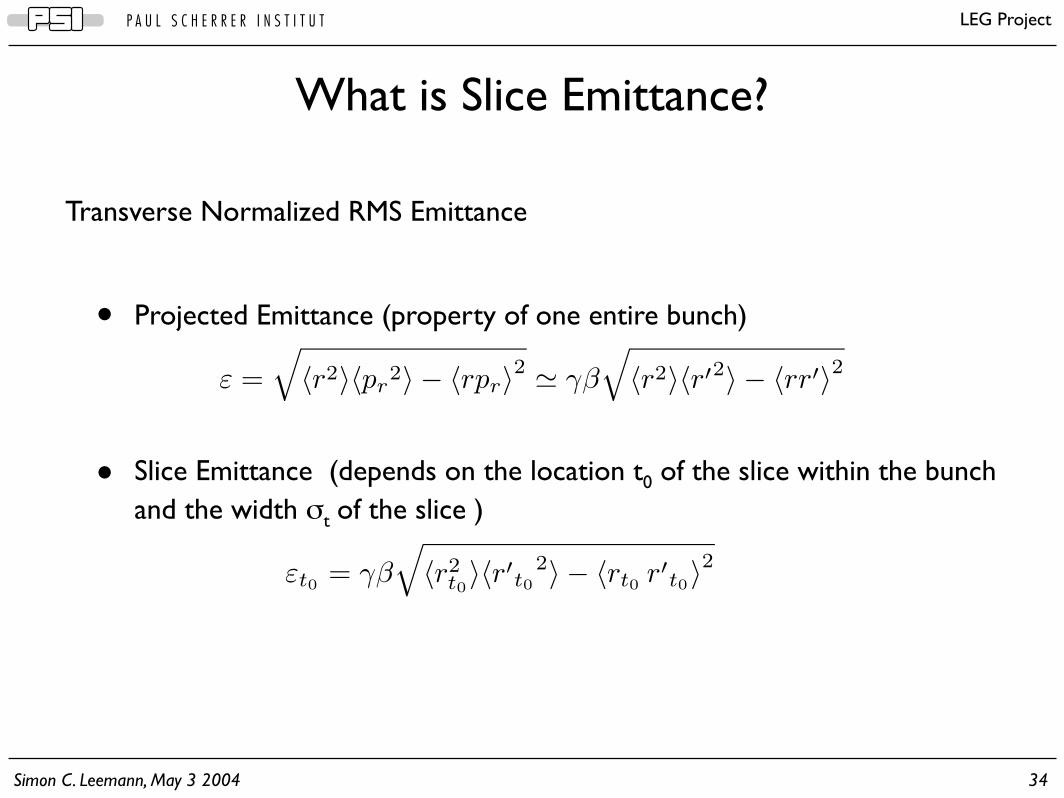
ε =√〈r2〉〈pr
2〉 − 〈rpr〉2 $ γβ√〈r2〉〈r′2〉 − 〈rr′〉2
Transverse Normalized RMS Emittance
• Projected Emittance (property of one entire bunch)
• Slice Emittance (depends on the location t0 of the slice within the bunch and the width σt of the slice )
What is Slice Emittance?
εt0 = γβ√〈r2
t0〉〈r′t0
2〉 − 〈rt0 r′t0〉2

Simon C. Leemann, May 3 2004 35
P A U L S C H E R R E R I N S T I T U T LEG Project
= e− (zi−z0)2
2β2c2σ2
How do we calculate Slice Emittance?
wi,0 = e−(ti−t0)2
2σ2
W0 =N∑
i=1
wi,0
〈r2t0〉 =
1W0
N∑i=1
ri2 · wi,0

Simon C. Leemann, May 3 2004 36
P A U L S C H E R R E R I N S T I T U T LEG Project
Slice Emittance Example
σz = 0.3 mm

Simon C. Leemann, May 3 2004 37
P A U L S C H E R R E R I N S T I T U T LEG Project
• Gun Geometries
• Parameter Studies
• Solenoid Field
• Diode Gap
• Bunch Charge
• Bunch Length
• Active Emitter Area
• Scaling Laws and Extrapolation
• Projected Emittance and Slice Emittance
• Conclusions
Topics

Simon C. Leemann, May 3 2004 38
P A U L S C H E R R E R I N S T I T U T LEG Project
Conclusions (1)Gun Design:
• We’re able to maintain a peak electric field strength < 20 MV/m
• By choosing a proper cathode electrode tilt angle we’ve managed to reduce the norm. transv. emittance to 6.10-8 m.rad
• By closing the gap between the electrodes the emittance can be further minimized to levels well below 10-8 m.rad
» How far will material and vacuum conditions allow us to go?
Solenoid:
• Using a properly tuned solenoid the emittance can be minimized at a certain location of interest
• Currently the minimum achieved norm. transv. emittance at the exit of the structure (z = 34 cm) is 2.4.10-8 m.rad
Simon C. Leemann, May 3 2004 39
P A U L S C H E R R E R I N S T I T U T LEG Project
Conclusions (2)Bunch Charge:
• The amount of charge inserted into the bunch scales the emittance roughly linear if we have properly tuned solenoid focussing
Bunch Length:
• Without solenoid focussing lengthening the bunch leads to lower emittance
• With solenoid focussing there is a bunch length that minimizes emittance
Active Emitter Area:
• For a given anode iris radius there is an optimum active emitter radius
• For a given FEA the ratio of active emitter radius and anode iris radius can be optimized for minimum emittance

Simon C. Leemann, May 3 2004 40
P A U L S C H E R R E R I N S T I T U T LEG Project
Conclusions (3)Extrapolating Results:
• In general we can not extrapolate exact results for longer bunches, but we can estimate upper limits for ε
• This has to do with the fact that our bunches are neither disk-shaped nor cigar-shaped, but rather between these two limits where the space charge forces depend strongly on the bunch geometry (ratio between bunch length and radial bunch envelope)
Slice Emittance:
• We can calculate slice emittance values for a bunch and compare with the projected emittance, but parameters have to be properly chosen due to the trade-off between numerical noise and possible resolution
• As expected the slice emittance in the center of the bunch is much smaller than the projected emittance of the entire bunch