Embed Size (px)
Citation preview

8/9/2019 1W_PG1N-1LxD_v2.4
http://slidepdf.com/reader/full/1wpg1n-1lxdv24 1/13
ProLight PG1N-1LxD1W Star/O
Technical Datasheet
Version: 2.4
Features High Flux per LED
Various colors
Viewing angle: 2θ1/2=40°, 2θ0.3=60°
Good color uniformity
More energy efficient than incandescent and
most halogen lamps
Low Voltage DC operated
Instant light (less than 100ns)
No UV
Superior ESD protection
Typical Applications Reading lights (car, bus, aircraft)
Portable (flashlight, bicycle)
Uplighters/Downlighters
Decorative/Entertainment
Bollards/Security/Garden
Cove/Undershelf/Task
Indoor/Outdoor Commercial and
Residential Architectural
Automotive Ext (Stop-Tail-Turn,
CHMSL, Mirror Side Repeat)
1 2009/02
Technology Corporation

8/9/2019 1W_PG1N-1LxD_v2.4
http://slidepdf.com/reader/full/1wpg1n-1lxdv24 2/13
Star/O Mechanical Dimensions
2
Notes:
1. Slots in aluminum-core PCB for M3 or #4 mounting screw.
2. Electrical interconnection pads labeled on the aluminum-core PCB with "+" and "-" to denote
positive and negative, respectively. All positive pads are interconnected, as are all negative pads,
allowing for flexibility in array interconnection.
3. Do not subject to temperatures greater than 75°C as plastic deformation may occur.
Protect collimator against exposure to solvents and adhesives that are not compatible with it.
Use care in handling the optic to avoid scratches or other damage that will effect the optical
performance.
4. Drawing not to scale.5. All dimensions are in millimeters.
6. All dimendions without tolerances are for reference only.
*The appearance and specifications of the product may be modified for improvement without notice.
8/9/2019 1W_PG1N-1LxD_v2.4
http://slidepdf.com/reader/full/1wpg1n-1lxdv24 3/13
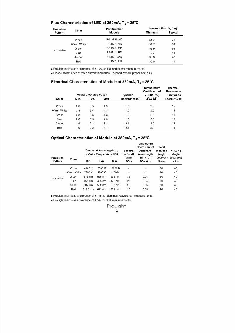
Flux Characteristics of LED at 350mA, TJ = 25°C
Radiation
Pattern Minimum Typical
White 51.7 72Warm White 51.7 68
Green 58.9 66
Blue 10.7 14
Amber 30.6 42
Red 30.6 40
ProLight maintains a tolerance of ± 10% on flux and power measurements.
Please do not drive at rated current more than 3 second without proper heat sink.
Electrical Characteristics of Module at 350mA, TJ = 25°CTemperature Thermal
Coefficient of Resistance
Dynamic VF (mV/ °C) Junction to
Color Resistance (Ω) ΔVF / ΔTJ Board (°C/ W)
White 1.0 -2.0 15
Warm White 1.0 -2.0 15
Green 1.0 -2.0 15
Blue 1.0 -2.0 15
Amber 2.4 -2.0 15Red 2.4 -2.0 15
Optical Characteristics of Module at 350mA, TJ = 25°C
ProLight maintains a tolerance of ± 1nm for dominant wavelength measurements.
ProLight maintains a tolerance of ± 5% for CCT measurements.
3
Lambertian
2.8 3.5 4.3
2.8 3.5 4.3
PG1N-1LWD
PG1N-1LVD
PG1N-1LGD
PG1N-1LBD
PG1N-1LAD
PG1N-1LRD
Lumious Flux ΦV (lm)
1.9 2.2 3.11.9 2.2 3.1
Forward Voltage VF (V)
Color Part Number
Min. Typ. Max.
2.8 3.5 4.3
2.8 3.5 4.3
Module
Temperature
Coefficient of Total
Spectral Dominant included Viewing
Half-width Wavelength Angle Angle
Radiation (nm) (nm/ °C) (degrees) (degrees)
Pattern Min. Typ. Max. Δλ1/2 ΔλD / ΔTJ θ0.90V 2 θ1/2
White 4100 K 5500 K 10000 K --- --- 90 40
Warm White 2700 K 3300 K 4100 K --- --- 90 40
Green 515 nm 525 nm 535 nm 35 0.04 90 40
Blue 455 nm 465 nm 475 nm 25 0.04 90 40
Amber 587 nm 592 nm 597 nm 20 0.05 90 40
Red 613.5 nm 623 nm 631 nm 20 0.05 90 40
Dominant Wavelength λD,
or Color Temperature CCT
Lambertian
Color

8/9/2019 1W_PG1N-1LxD_v2.4
http://slidepdf.com/reader/full/1wpg1n-1lxdv24 4/13
Absolute Maximum Ratings
Parameter
DC Forward Current (mA)
Peak Pulsed Forward Current (mA)Average Forward Current (mA)
ESD Sensitivity
(HBM per MIL-STD-883E Method 3015.7)
LED Junction Temperature (°C)
Aluminum-core PCB Temperature (°C)
Storage & Operating Temperature (°C)
Photometric Luminous Flux Bin Structure of LED
Color Bin Code
S1
S2
T1
T2
S1
S2
T1
T2*When CCT is less than 3050K, T2 bin is not available.
S2
T1
L
M
Q
R
Q
R
ProLight maintains a tolerance of ± 10% on flux and power measurements.
The flux bin of the product may be modified for improvement without notice.
±4000V (Class III)
30.6 39.8
39.8 51.7
67.2 76.6
10.7 13.9
76.6 87.4
58.9 67.2
Red
Minimum Photometric Flux (lm) Maximum Photometric Flux (lm)
White
51.7 58.9
58.9 67.2
67.2 76.6
Blue13.9 18.1
Amber30.6 39.8
39.8 51.7
Warm White
51.7 58.9
Green58.9 67.2
67.2 76.6
76.6 87.4
4
350
120
75
-40 to +75
Green/Blue/Amber/Red
350
500
White/Warm White/
8/9/2019 1W_PG1N-1LxD_v2.4
http://slidepdf.com/reader/full/1wpg1n-1lxdv24 5/13
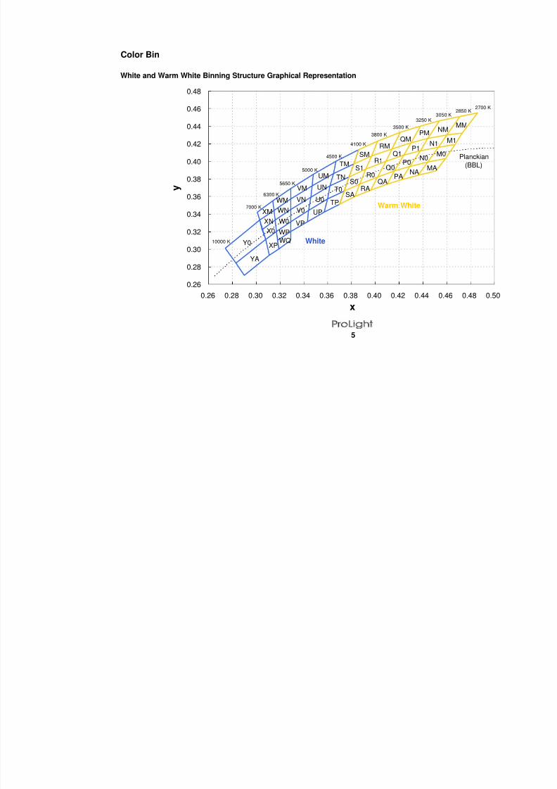
Color Bin
White and Warm White Binning Structure Graphical Representation
5
0.26
0.28
0.30
0.32
0.34
0.36
0.38
0.40
0.42
0.44
0.46
0.48
0.26 0.28 0.30 0.32 0.34 0.36 0.38 0.40 0.42 0.44 0.46 0.48
x
y
10000 K
7000 K
6300 K
5650 K
5000 K
4500 K
4100 K
3800 K
3500 K
3250 K3050 K
2850 K
R0
RA
Q0
QA
R1 P0
P1
PA
M0
M1
MA
N0
N1
NA
Y0
YA
TM
TN
T0
UM
UN
U0
UPV0
VM
VN
VPX0
XP
XM
XN W0
WM
WN
WP
WQ
Q1
S0
SM
S1
TPSA
MMNM
PMQM
RM
Planc
(BB
Warm White
White

8/9/2019 1W_PG1N-1LxD_v2.4
http://slidepdf.com/reader/full/1wpg1n-1lxdv24 6/13
Color Bins
White Bin Structure
Bin Code x yTyp. CCT
(K)Bin Code x y
Typ. CCT
(K)
0.378 0.382 0.329 0.3450.374 0.366 0.329 0.3310.360 0.357 0.317 0.3200.362 0.372 0.316 0.3330.382 0.397 0.329 0.3450.378 0.382 0.316 0.3330.362 0.372 0.315 0.3440.365 0.386 0.329 0.357
0.374 0.366 0.329 0.3310.370 0.351 0.329 0.3200.357 0.342 0.318 0.3100.360 0.357 0.317 0.3200.386 0.413 0.329 0.320
0.382 0.397 0.329 0.3100.365 0.386 0.319 0.3000.367 0.400 0.318 0.3100.362 0.372 0.329 0.3690.360 0.357 0.329 0.3570.344 0.344 0.315 0.3440.346 0.359 0.314 0.355
0.365 0.386 0.308 0.3110.362 0.372 0.305 0.3220.346 0.359 0.316 0.3330.347 0.372 0.317 0.320
0.360 0.357 0.305 0.3220.357 0.342 0.303 0.333
0.343 0.331 0.315 0.3440.344 0.344 0.316 0.3330.365 0.386 0.308 0.3110.367 0.400 0.317 0.3200.348 0.385 0.319 0.3000.347 0.372 0.311 0.2930.329 0.331 0.301 0.3420.329 0.345 0.314 0.3550.346 0.359 0.315 0.3440.344 0.344 0.303 0.333
0.329 0.345 0.308 0.3110.329 0.357 0.283 0.2840.347 0.372 0.274 0.301
0.346 0.359 0.303 0.3330.329 0.331 0.308 0.3110.344 0.344 0.311 0.2930.343 0.331 0.290 0.2700.329 0.320 0.283 0.2840.329 0.3570.329 0.3690.348 0.3850.347 0.372
Tolerance on each color bin (x , y) is ± 0.01
Note: Although several bins are outlined, product availability in a particular bin varies by production run
and by product performance. Not all bins are available in all colors.
6
XP 6650
XM 6650
UM 4750
V0 5320
VN
UP 4750 XN 6650
4750 WM 5970
UN 4750 X0 6650
U0
TN 4300 WN 5970
T0 4300 W0 5970
4300 WP 5970TP
TM 4300 WQ 5970
5320 Y0 8000
VP 5320 YA 8000
VM 5320

8/9/2019 1W_PG1N-1LxD_v2.4
http://slidepdf.com/reader/full/1wpg1n-1lxdv24 7/13
Color Bins
Warm White Bin Structure
Bin Code x yTyp. CCT
(K)Bin Code x y
Typ. CCT
(K)
0.453 0.416 0.409 0.4000.444 0.399 0.402 0.3820.459 0.403 0.416 0.3890.467 0.419 0.424 0.4070.460 0.430 0.414 0.4140.453 0.416 0.409 0.4000.467 0.419 0.424 0.4070.473 0.432 0.430 0.421
0.459 0.403 0.416 0.3890.444 0.399 0.402 0.3820.436 0.384 0.396 0.3670.451 0.389 0.410 0.3740.471 0.451 0.421 0.433
0.460 0.430 0.414 0.4140.473 0.432 0.430 0.4210.486 0.455 0.438 0.4400.438 0.412 0.392 0.3910.429 0.394 0.387 0.3740.444 0.399 0.402 0.3820.453 0.416 0.409 0.400
0.444 0.426 0.414 0.4140.438 0.412 0.409 0.4000.453 0.416 0.392 0.3910.460 0.430 0.397 0.406
0.444 0.399 0.387 0.3740.429 0.394 0.383 0.360
0.422 0.379 0.396 0.3670.436 0.384 0.402 0.3820.454 0.446 0.421 0.4330.444 0.426 0.414 0.4140.460 0.430 0.397 0.4060.471 0.451 0.402 0.4230.424 0.407 0.392 0.3910.416 0.389 0.387 0.3740.429 0.394 0.374 0.3660.438 0.412 0.378 0.382
0.430 0.421 0.397 0.4060.424 0.407 0.392 0.3910.438 0.412 0.378 0.382
0.444 0.426 0.382 0.3970.429 0.394 0.387 0.3740.416 0.389 0.383 0.3600.410 0.374 0.370 0.3510.422 0.379 0.374 0.3660.438 0.440 0.402 0.4230.430 0.421 0.397 0.4060.444 0.426 0.382 0.3970.454 0.446 0.386 0.413
Tolerance on each color bin (x , y) is ± 0.01
Note: Although several bins are outlined, product availability in a particular bin varies by production run
and by product performance. Not all bins are available in all colors.
3150 SM 3950
NM 2950 RM 3650
P0 3150 S0
3370MA
N0 2950 R0 3650
MM 2770 QM 3370
3370
M0 2770 Q0 3370
N1
M1 2770 Q1
2770 QA
NA 2950 RA 3650
3150
2950 R1 3650
PM
3950
7
S1 3950
SA 3950
P1 3150
PA

8/9/2019 1W_PG1N-1LxD_v2.4
http://slidepdf.com/reader/full/1wpg1n-1lxdv24 8/13
Dominant Wavelength Bin Structure
A
1
2
3
A
1
2
3
2
4
67
2
4
ProLight maintains a tolerance of ± 1nm for dominant wavelength measurements.
Note: Although several bins are outlined, product availability in a particular bin varies by production run
and by product performance. Not all bins are available in all colors.
8
Wavelength (nm) Wavelength (nm)
Amber
Red
Blue
Green
515 520
520 525
530
535
525
530
475470
455
460
465
460
465
470
594.5
589.5
592.0
594.5597.0
587.0
589.5
592.0
620.5
631.0
613.5
620.5
Minimum Dominant Maximum DominantBin CodeColor

8/9/2019 1W_PG1N-1LxD_v2.4
http://slidepdf.com/reader/full/1wpg1n-1lxdv24 9/13
Color Spectrum, TJ = 25°C
1. White
2. Warm White
3. Blue、Green、Amber、Red
9
0.0
0.2
0.4
0.6
0.8
1.0
350 400 450 500 550 600 650 700 750 800 850
Wavelength(nm)
R e l a t i v e S p e c t r a l P o w e r
D i s t r i b u t i o n
Standard Eye Response Cruve
White
0.0
0.2
0.4
0.6
0.8
1.0
350 400 450 500 550 600 650 700 750 800 850
Wavelength(nm)
R e l a t i v e S p e c t r a l P o w e r
D i s t r i b u t i o n
Standard Eye Response Cruve Warm White
0.0
0.2
0.4
0.6
0.8
1.0
400 450 500 550 600 650 700
Wavelength(nm)
R e l a t i v e S p e c t r a l P
o w e r
D i s t r i b u t i o n
Blue Green Amber Red
8/9/2019 1W_PG1N-1LxD_v2.4
http://slidepdf.com/reader/full/1wpg1n-1lxdv24 10/13
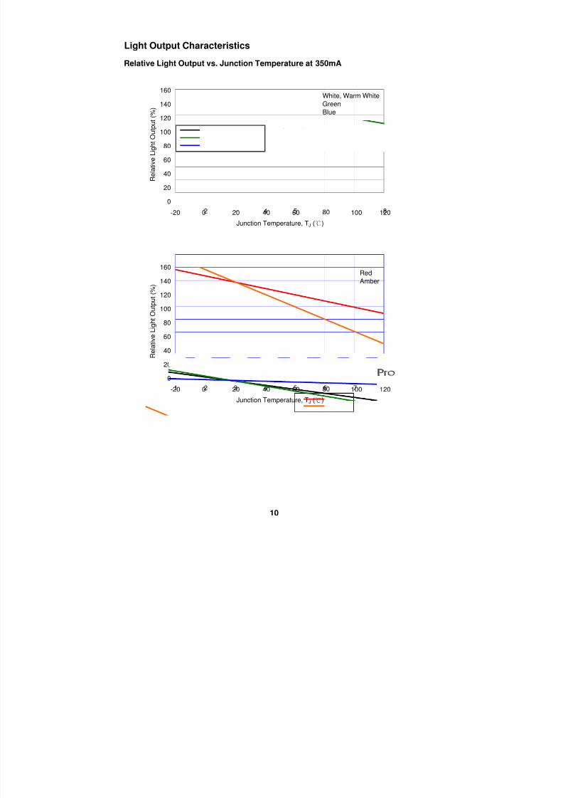
Light Output Characteristics
Relative Light Output vs. Junction Temperature at 350mA
10
0
20
40
60
80
100
120
140
160
1 2 3 4 5 6 7 8
Junction Temperature, TJ ()
R e l a t i v e L i g h t O u t p u t ( % )
-20 0 20 40 60 80 100 120
White, Warm WhiteGreen
Blue
0
20
40
60
80
100
120
140
160
1 2 3 4 5 6 7 8
Junction Temperature, TJ ()
R e l a t i v e L i g h t O u t p u t ( % )
-20 0 20 40 60 80 100 120
Red
Amber
8/9/2019 1W_PG1N-1LxD_v2.4
http://slidepdf.com/reader/full/1wpg1n-1lxdv24 11/13
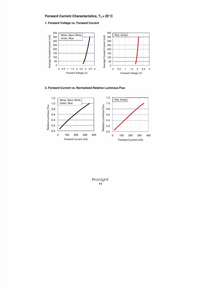
Forward Current Characteristics, TJ = 25°C
1. Forward Voltage vs. Forward Current
2. Forward Current vs. Normalized Relative Luminous Flux
11
0
50
100
150
200
250
300
350
400
0 0.5 1 1.5 2 2.5 3
Forward Voltage (V)
A v e r a g e F o r w a r d C u r r e n t ( m A ) Red, Amber
0
50
100
150
200
250
300
350
400
0 0.5 1 1.5 2 2.5 3 3.5 4
Forward Voltage (V)
A v e r a g e F o r w a r d C u r r e n t ( m A ) White, Warm White,
Green, Blue
0.0
0.2
0.4
0.6
0.8
1.0
1.2
0 100 200 300 400
Forward Current (mA)
R e l a t i v e L u m i n o u s F l u x
White, Warm White,
Green, Blue
0.0
0.2
0.4
0.6
0.8
1.0
1.2
0 100 200 300 400
Forward Current (mA)
R e l a t i v e L u m i n o u s F l u
x
Red, Amber
8/9/2019 1W_PG1N-1LxD_v2.4
http://slidepdf.com/reader/full/1wpg1n-1lxdv24 12/13
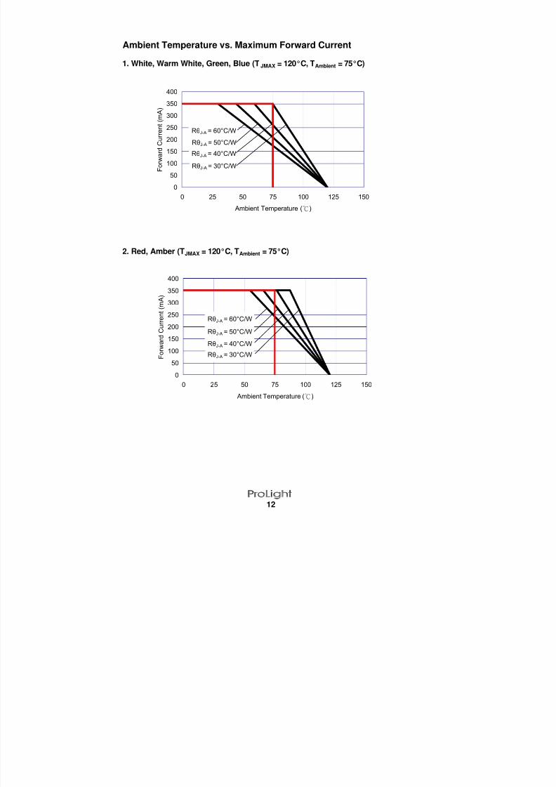
Ambient Temperature vs. Maximum Forward Current
1. White, Warm White, Green, Blue (TJMAX = 120°C, TAmbient = 75°C)
2. Red, Amber (TJMAX = 120°C, TAmbient = 75°C)
12
0
50
100
150
200
250
300
350
400
0 25 50 75 100 125 150
Ambient Temperature ()
F o r w a r d C u r r e n t ( m A )
RθJ-A = 60°C/W
RθJ-A = 50°C/W
RθJ-A = 30°C/W
RθJ-A = 40°C/W
0
50
100
150
200
250
300
350
400
0 25 50 75 100 125 150
Ambient Temperature ()
F o r w a r d C u r r e n t ( m A )
RθJ-A = 60°C/W
RθJ-A = 50°C/W
RθJ-A = 30°C/W
RθJ-A = 40°C/W
8/9/2019 1W_PG1N-1LxD_v2.4
http://slidepdf.com/reader/full/1wpg1n-1lxdv24 13/13
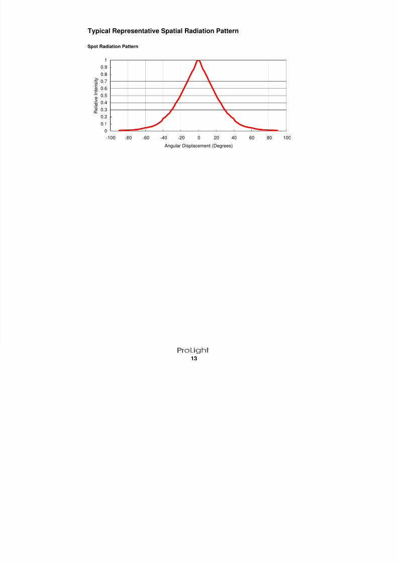
Typical Representative Spatial Radiation Pattern
Spot Radiation Pattern
13
0
0.1
0.2
0.3
0.4
0.5
0.6
0.7
0.8
0.9
1
-100 -80 -60 -40 -20 0 20 40 60 80 100Angular Displacement (Degrees)
R e l a t i v e I n t e n s i t y
0
0.1
0.2
0.3
0.4
0.5
0.6
0.7
0.80.9
1
-100 -80 -60 -40 -20 0 20 40 60 80 100Angular Displacement (Degrees)
R e l a t i v e I n t e n s i t y


