Embed Size (px)
Citation preview

Proceedings of the Geoterminology Workshop (1990) Published and sponsored jointly by the:
ASSOCIATION OF ENGINEERING GEOLOGISTS - South Africa Section (AEG – SA Section) SOUTH AFRICAN INSTITUTION OF CIVIL ENGINEERING Geotechnical Division (SAICE) SOUTH AFRICAN INSTITUTE FOR ENGINEERING AND ENVIRONMENTAL GEOLOGISTS (SAIEG)
�
�
�
�
�
�
�
��������������
���� ����������������
�������� ��� �
2nd Impression 2002
Editors ABA Brink & RMH Bruin
Gui
delin
es

Guidelines for Soil and Rock Logging in SA
Page 1
GEOTERMINOLOGY WORKSHOP (1990)
GUIDELINES FOR SOIL AND ROCK LOGGING IN SA
Published and Sponsored jointly by the:
ASSOCIATION OF ENGINEERING GEOLOGISTS - SOUTH AFRICA SECTION (AEG – SA SECTION)
SOUTH AFRICAN INSTITUTION OF CIVIL ENGINEERS
Geotechnical Division (SAICE)
SOUTH AFRICAN INSTITUTE FOR ENGINEERING AND ENVIRONMENTAL
GEOLOGISTS (SAIEG)
All rights reserved. No part of this guide may be reproduced, broadcast or transmitted in any form or by any means, electronically, mechanically, including photocopying, recording or by information storage or in any retrieval system without the prior permission of the Geotechnical Division of the
South African Institution of Civil Engineers.
Every effort has been made to ensure that the information and data presented in the Guide are correct. The Sponsors, Editors and the Committee are not responsible for any errors or omissions, or for any consequences resulting from these errors or omissions. The views
expressed in the Guide are not necessarily those of the Sponsors.
The Guide can be purchased from:
SAICE Geotechnical Division
P.O. Box 1434 RIVONIA
2128 Reference for this document: Guidelines for Soil and Rock Logging in South Africa, 2nd Impression 2001, eds. A.B.A. Brink and R.M.H. Bruin, Proceedings, Geoterminology Workshop organised by AEG, SAICE and SAIEG, 1990.

Page 2 Guidelines for Soil and Rock Logging in SA

Guidelines for Soil and Rock Logging in SA
Page 3
SECTIONS
Page Section 1: Guide to Soil Profiling for Civil Engineering Purposes .......................5 Section 2: Guide to Percussion Borehole Logging ............................................27 Section 3: Guide to Core Logging for Civil Engineering Purposes ....................39

Page 4 Guidelines for Soil and Rock Logging in SA
Guidelines for Soil and Rock Logging in SA
Page 5
Guide to Soil Profiling for Civil Engineering Purposes
Sec
tion
1
Page 6 Guidelines for Soil and Rock Logging in SA
FOREWORD
The South African geotechnical fraternity has been most fortunate in having some excellent guidelines to work to. These arise out of the work done by the pioneers under the influence of the late Professor J E Jennings. At an evening meeting sponsored by the Association of Engineering Geologists in June 1987 on the subject of Geoterminology some 109 attendees partook in lively debates which confirmed that the practitioners consider certain aspects of the existing guidelines required modification. To enable the revisions to be carried out with the widest possible consensus a specialist committee under the chairmanship of R.M.H. Bruin was constituted with the task of revising and updating the guidelines for the 1990’s. The format chosen consisted of written submissions from the fraternity followed by an afternoon workshop in October 1990 to debate the revisions and to achieve consensus by majority vote. Final drafts of the revisions from the various sub-committees were received in late 1991 which were edited and made available for final review by the Sponsors in 1993. This Guide represents the efforts of a dedicated group of engineering geologists and civil engineers from the Sponsors who have spent many months updating and revising the Guide first published in 1958 and revised in 1973 by Jennings et al. It is not meant to teach one how to carry out the exercise of soil profiling but rather the descriptors to be used and the definitions thereof so that a clear understanding of the ground conditions is communicated by the recorder to the user. The committee has recorded all pertinent revisions as well as conducted a thorough search of the worldwide publications to produce this uniquely South African publication which should stand the profession in good stead for many years to come. The guide will be applicable for many parts of the world due to its simplicity. Its ease of use stems from the gestalt approach to soil profiling as practised in southern Africa. A.B.A. Brink Editor R.M.H. Bruin Chairman and co-editor June 1994 COMMITTEE
The Committee responsible for the production of this Guide on behalf of the Sponsors: Chairman and Editor : R.M.H. Bruin, Pr. Sci Nat. Editor : A.B.A. Brink, Pr. Sci Nat. Committee : K. Schwartz, Pr. Eng. D. Warwick, Pr. Sci Nat. The contributions from the 34 attendees and the written submissions both prior and subsequent to the workshop on 16 October 1990 are gratefully acknowledged.
Guidelines for Soil and Rock Logging in SA
Page 7
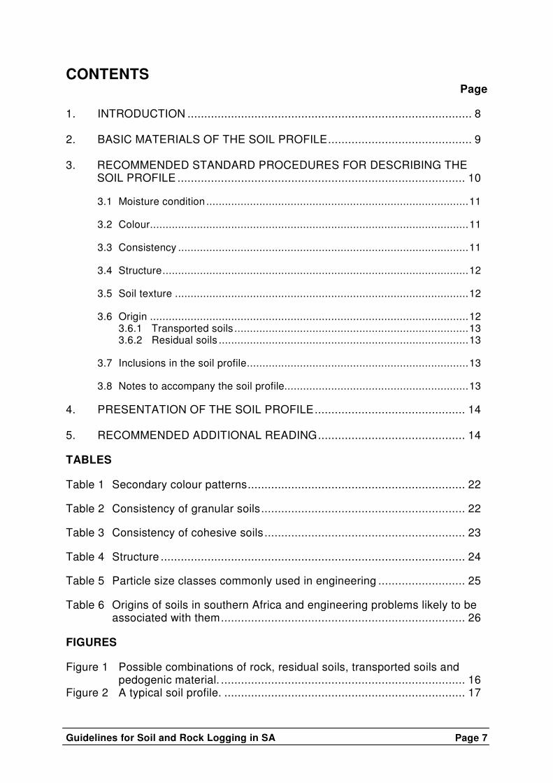
CONTENTS Page
1. INTRODUCTION ..................................................................................... 8 2. BASIC MATERIALS OF THE SOIL PROFILE........................................... 9 3. RECOMMENDED STANDARD PROCEDURES FOR DESCRIBING THE
SOIL PROFILE ...................................................................................... 10 3.1 Moisture condition ....................................................................................11 3.2 Colour......................................................................................................11 3.3 Consistency .............................................................................................11 3.4 Structure..................................................................................................12 3.5 Soil texture ..............................................................................................12 3.6 Origin ......................................................................................................12 3.6.1 Transported soils ...........................................................................13 3.6.2 Residual soils ................................................................................13 3.7 Inclusions in the soil profile.......................................................................13 3.8 Notes to accompany the soil profile...........................................................13 4. PRESENTATION OF THE SOIL PROFILE............................................. 14 5. RECOMMENDED ADDITIONAL READING............................................ 14
TABLES Table 1 Secondary colour patterns................................................................. 22 Table 2 Consistency of granular soils............................................................. 22 Table 3 Consistency of cohesive soils ............................................................ 23 Table 4 Structure ........................................................................................... 24 Table 5 Particle size classes commonly used in engineering .......................... 25 Table 6 Origins of soils in southern Africa and engineering problems likely to be
associated with them......................................................................... 26 FIGURES Figure 1 Possible combinations of rock, residual soils, transported soils and
pedogenic material. ......................................................................... 16 Figure 2 A typical soil profile. ........................................................................ 17
Page 8 Guidelines for Soil and Rock Logging in SA
GUIDE TO SOIL PROFILING FOR CIVIL ENGINEERING PURPOSES
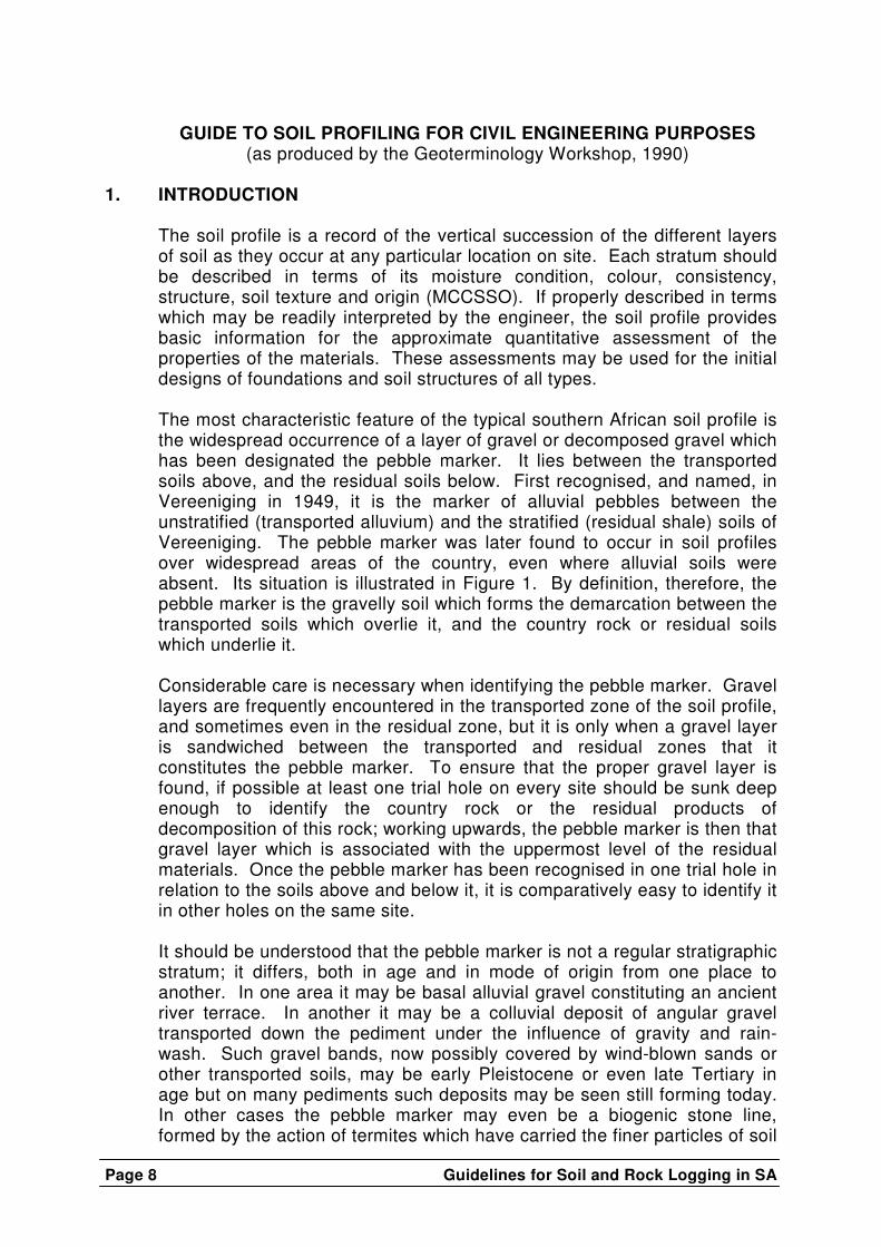
(as produced by the Geoterminology Workshop, 1990) 1. INTRODUCTION
The soil profile is a record of the vertical succession of the different layers of soil as they occur at any particular location on site. Each stratum should be described in terms of its moisture condition, colour, consistency, structure, soil texture and origin (MCCSSO). If properly described in terms which may be readily interpreted by the engineer, the soil profile provides basic information for the approximate quantitative assessment of the properties of the materials. These assessments may be used for the initial designs of foundations and soil structures of all types. The most characteristic feature of the typical southern African soil profile is the widespread occurrence of a layer of gravel or decomposed gravel which has been designated the pebble marker. It lies between the transported soils above, and the residual soils below. First recognised, and named, in Vereeniging in 1949, it is the marker of alluvial pebbles between the unstratified (transported alluvium) and the stratified (residual shale) soils of Vereeniging. The pebble marker was later found to occur in soil profiles over widespread areas of the country, even where alluvial soils were absent. Its situation is illustrated in Figure 1. By definition, therefore, the pebble marker is the gravelly soil which forms the demarcation between the transported soils which overlie it, and the country rock or residual soils which underlie it. Considerable care is necessary when identifying the pebble marker. Gravel layers are frequently encountered in the transported zone of the soil profile, and sometimes even in the residual zone, but it is only when a gravel layer is sandwiched between the transported and residual zones that it constitutes the pebble marker. To ensure that the proper gravel layer is found, if possible at least one trial hole on every site should be sunk deep enough to identify the country rock or the residual products of decomposition of this rock; working upwards, the pebble marker is then that gravel layer which is associated with the uppermost level of the residual materials. Once the pebble marker has been recognised in one trial hole in relation to the soils above and below it, it is comparatively easy to identify it in other holes on the same site. It should be understood that the pebble marker is not a regular stratigraphic stratum; it differs, both in age and in mode of origin from one place to another. In one area it may be basal alluvial gravel constituting an ancient river terrace. In another it may be a colluvial deposit of angular gravel transported down the pediment under the influence of gravity and rain-wash. Such gravel bands, now possibly covered by wind-blown sands or other transported soils, may be early Pleistocene or even late Tertiary in age but on many pediments such deposits may be seen still forming today. In other cases the pebble marker may even be a biogenic stone line, formed by the action of termites which have carried the finer particles of soil

Guidelines for Soil and Rock Logging in SA
Page 9
up to the surface to build their termitaries leaving a concentration of particles of up to 2mm in size below the surface. Although the pebble marker has been encountered over widespread areas there are areas where the transported zone overlies the residual zone directly without the transition of a pebble marker. Even on a restricted site the pebble marker may be present in some of the trial holes and very poorly developed or even absent in others. This should not disturb the observer; in such cases, one should direct one’s attention primarily towards establishing the level at which transported soils meet residual soils, i.e. the level at which the pebble marker would have occurred had it been present. For example, in certain areas of the Free State Goldfields, there is evidence that the pebble marker did exist in former times, in the form of dolerite, shale and sandstone fragments overlying the Karoo sediments, but that these gravel fragments themselves have now weathered down into the clays, silts and sands respectively. From the engineer’s point of view the pebble marker, representing the boundary between transported and residual soils, is of very great importance. First, it sometimes represents a stratum of free drainage which must be sealed off in certain forms of construction such as dams or, if drainage is required, it may be retained and be usefully employed for providing a free flow of water. Secondly, it indicates the level below which soil behaviour may be approximately predicted from other experience with similar decomposed rock types. Geological information will also give the approximate stratigraphic thickness of the rocks concerned and if the country rocks are of types which allow one to accept the principle that the degree of weathering will decrease with depth, then considerable subsoil information is provided to a great depth without the need for deep and expensive boreholes. One of the first points in observing profiles is therefore the recognition of the pebble marker.
2. BASIC MATERIALS OF THE SOIL PROFILE
Materials occurring in the soil profile fall into one of four natural categories, viz. Rock, residual soil, transported soil and pedogenic material. Possible combinations of these in the soil profile are illustrated in Figure 1.
In the engineering sense, and with particular reference to southern African occurrences, these four categories of naturally occurring materials may be defined as follows:
Rock – igneous, metamorphic or sedimentary material, other than pedogenic material, with an unconfined compressive strength of the intact or unjointed material in excess of 1 MPa.
Residual soil – material formed by the in situ decomposition (chemical weathering) or the disintegration (physical weathering) of
Page 10 Guidelines for Soil and Rock Logging in SA
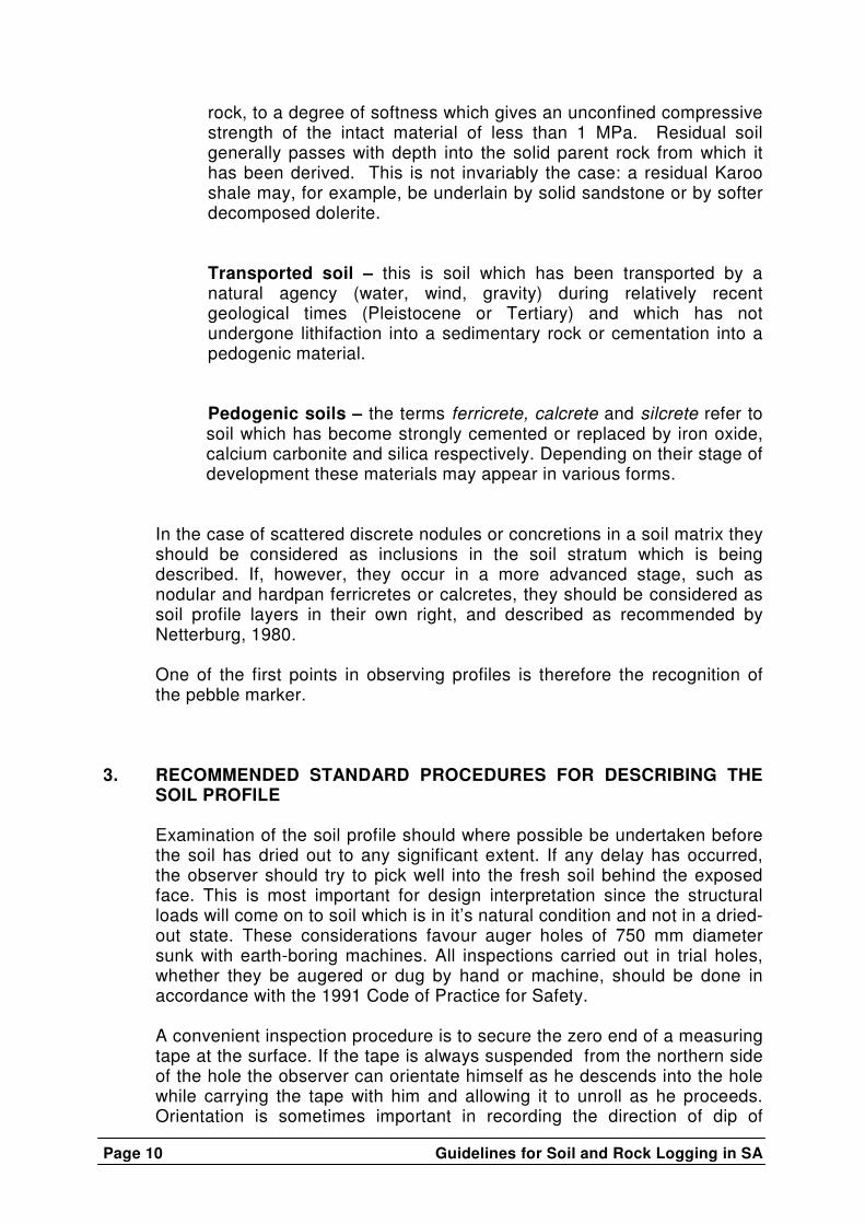
rock, to a degree of softness which gives an unconfined compressive strength of the intact material of less than 1 MPa. Residual soil generally passes with depth into the solid parent rock from which it has been derived. This is not invariably the case: a residual Karoo shale may, for example, be underlain by solid sandstone or by softer decomposed dolerite.
Transported soil – this is soil which has been transported by a natural agency (water, wind, gravity) during relatively recent geological times (Pleistocene or Tertiary) and which has not undergone lithifaction into a sedimentary rock or cementation into a pedogenic material.
Pedogenic soils – the terms ferricrete, calcrete and silcrete refer to soil which has become strongly cemented or replaced by iron oxide, calcium carbonite and silica respectively. Depending on their stage of development these materials may appear in various forms.
In the case of scattered discrete nodules or concretions in a soil matrix they should be considered as inclusions in the soil stratum which is being described. If, however, they occur in a more advanced stage, such as nodular and hardpan ferricretes or calcretes, they should be considered as soil profile layers in their own right, and described as recommended by Netterburg, 1980. One of the first points in observing profiles is therefore the recognition of the pebble marker.
3. RECOMMENDED STANDARD PROCEDURES FOR DESCRIBING THE
SOIL PROFILE Examination of the soil profile should where possible be undertaken before the soil has dried out to any significant extent. If any delay has occurred, the observer should try to pick well into the fresh soil behind the exposed face. This is most important for design interpretation since the structural loads will come on to soil which is in it’s natural condition and not in a dried-out state. These considerations favour auger holes of 750 mm diameter sunk with earth-boring machines. All inspections carried out in trial holes, whether they be augered or dug by hand or machine, should be done in accordance with the 1991 Code of Practice for Safety. A convenient inspection procedure is to secure the zero end of a measuring tape at the surface. If the tape is always suspended from the northern side of the hole the observer can orientate himself as he descends into the hole while carrying the tape with him and allowing it to unroll as he proceeds. Orientation is sometimes important in recording the direction of dip of

Guidelines for Soil and Rock Logging in SA
Page 11
bedding planes, foliations, etc. It may be necessary to have an electric light for deep holes, but far better illumination is obtained by reflecting sunlight down the hole with a mirror operated by an assistant at the surface. The procedures which are recommended for the field observation of moisture condition, colour, consistency, structure, soil texture and origin of each layer of the soil profile (MCCSSO) are as follows : 3.1 Moisture condition
The moisture condition of the layer of soil should be described as a necessary precursor to the assessment of consistency which is largely dependent on the moisture content at the time of inspection. This is recorded as one of the following: dry, slightly moist, moist, very moist, wet.
It will be appreciated that the interpretation of moisture condition in terms of approximate moisture content will depend on the grain size of the soil, e.g. a sand with a moisture content of 5% to 10% will be observed to be wet, while a clay at the same moisture content may be dry or only slightly moist.
Whatever the soil type may be, the assessment of moisture condition provides a useful indication of water requirements for compaction. Dry and slightly moist materials are near the optimum moisture content while very moist soils require drying to attain optimum moisture content. Wet soils generally come from below the water table.
3.2 Colour
The description of the predominant colours should simply be limited to two, e.g. reddish brown or blue-green . Secondary colour patterns are described according to their size limits (Table 1). A typical description for an alluvial clay would be ‘light grey mottled yellow’.
A proper description of colour as observed in the soil profile is difficult and few observers agree when their observations are made subjectively. The most satisfactory basis is provided by comparing the colours with those standards laid down in the Munsell colour charts, but these charts are difficult to use in confined and frequently dirty conditions encountered in trial holes. A simplified colour disc, the Burland colour disc, based on principles similar to those used for the Munsell charts, is available for purchase from the South African Institution of Civil Engineers. An experienced observer, however, will describe colour without recourse to colour charts.
3.3 Consistency Consistency is a measure of the hardness or toughness of the soil and is an observation based on the effort required to dig into the soil, or alternatively to mould it with the fingers. Since these operations

Page 12 Guidelines for Soil and Rock Logging in SA
involve shearing , the assessment of consistency is, in fact, a rough measure of its shear strength.
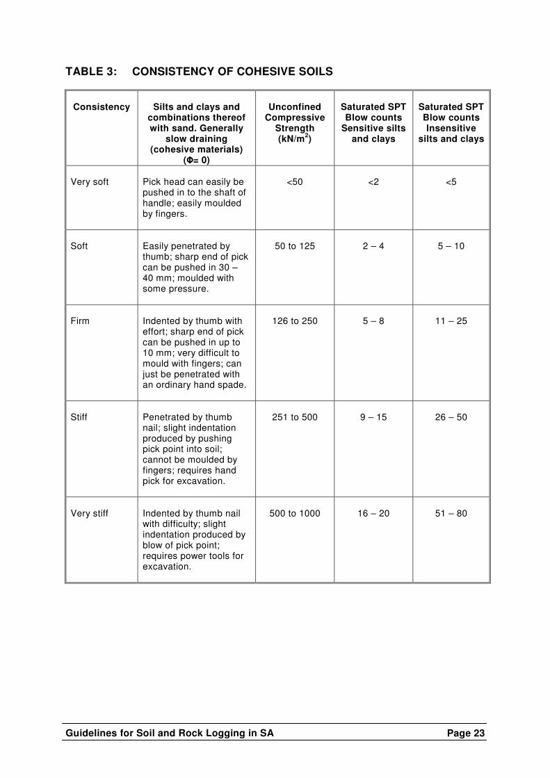
The recommended definitions of consistency are given in Tables 2 and 3. The separation of soils into cohesive and non-cohesive classes in order to describe consistency arises because of differences in permeability or drainage characteristics which profoundly affect shear strength.
In Table 3 the numerical values refer to unconfined compressive strength. If an estimate of the quick shear strength is required, the given values should be divided by two. However it should be remembered that in non-saturated soils or soils containing discontinuities these values may not be sufficiently conservative.
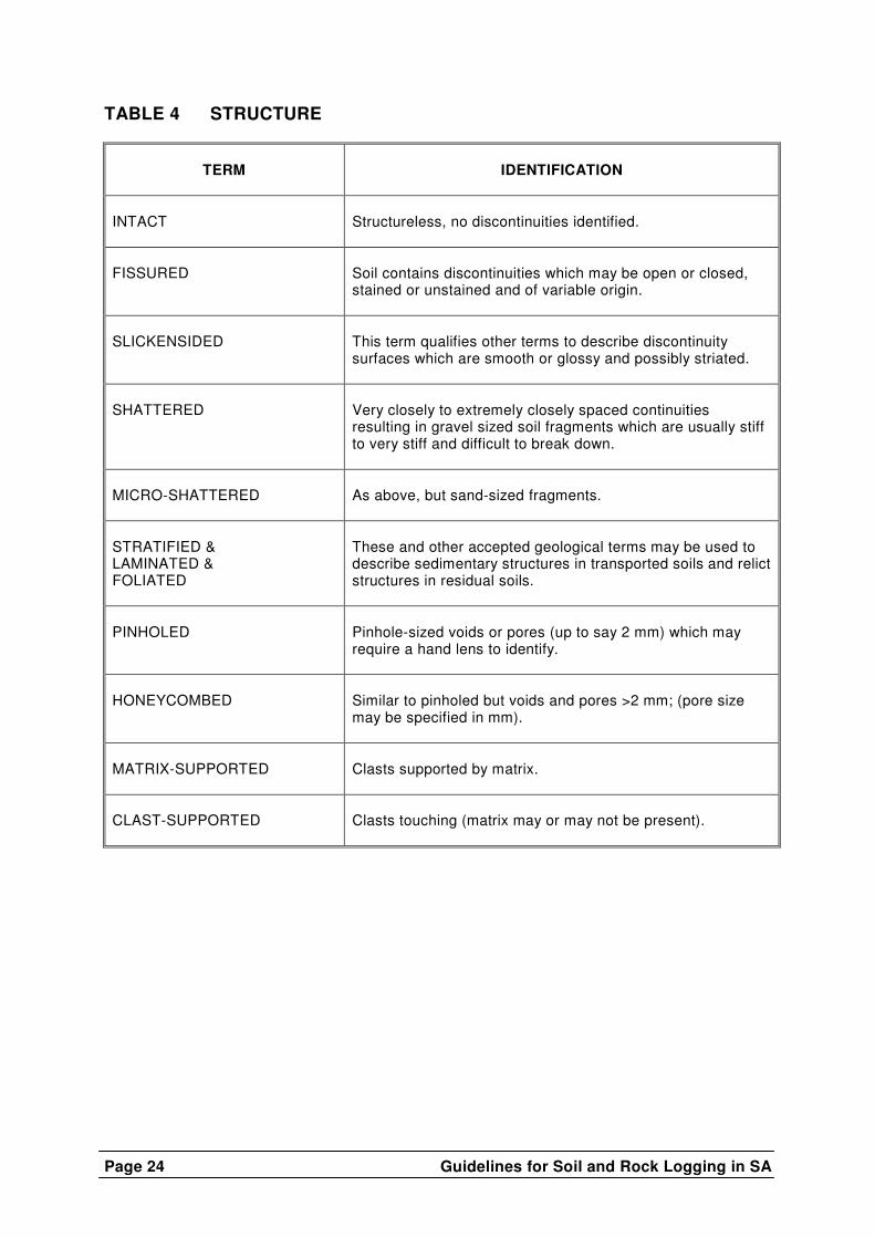
3.4 Structure
This term indicates the presence (or absence) of discontinuities in the soil and their nature. Non-cohesive soils exhibit a granular structure and since this is an invariable feature it is usually not recorded. On the other hand, cohesive soils exhibit several types of structural characteristics (Table 4).
3.5 Soil texture
The soil texture in each stratum is described on a basis of grain size (Table 5).
In the description of boulders, cobbles and gravels, particular care should be given to the description of the matrix and its relative volume. The shape of particles should also be described as this often aids the interpretation of origin. Recommended terms are :
well-rounded (nearly spherical) rounded (tending to oval shape) sub-rounded (all corners rounded off) sub-angular (corners slightly bevelled) angular (corners sharp or irregular)
Most natural soils are a combination of one or more textures and, in describing a soil, the adjective is used to denote the lesser type, e.g. a silty clay is a clay with some silt. A silt-clay however has approximately equal proportions of silt and clay.
3.6 Origin An attempt should be made to determine the origin of the soil in each layer of the soil profile. This is generally quite easy in the case of residual soils below the pebble marker, but may prove more difficult in the transported soil zone.
Guidelines for Soil and Rock Logging in SA
Page 13
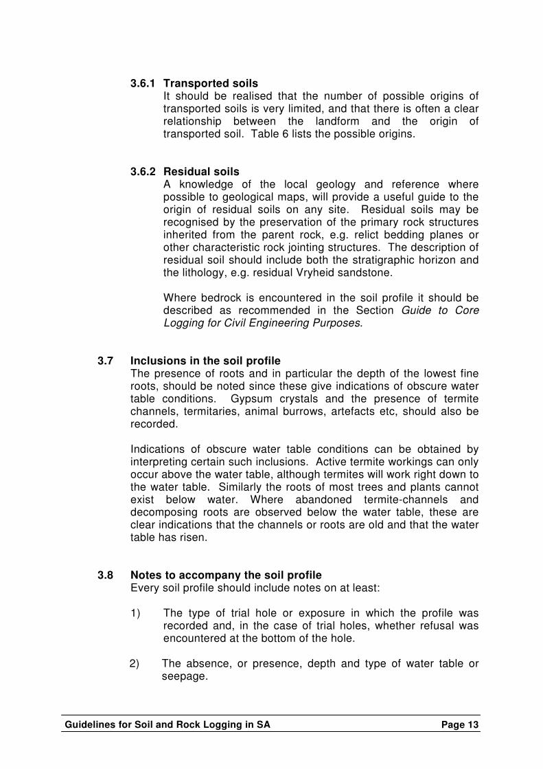
3.6.1 Transported soils
It should be realised that the number of possible origins of transported soils is very limited, and that there is often a clear relationship between the landform and the origin of transported soil. Table 6 lists the possible origins.
3.6.2 Residual soils
A knowledge of the local geology and reference where possible to geological maps, will provide a useful guide to the origin of residual soils on any site. Residual soils may be recognised by the preservation of the primary rock structures inherited from the parent rock, e.g. relict bedding planes or other characteristic rock jointing structures. The description of residual soil should include both the stratigraphic horizon and the lithology, e.g. residual Vryheid sandstone.
Where bedrock is encountered in the soil profile it should be described as recommended in the Section Guide to Core Logging for Civil Engineering Purposes.
3.7 Inclusions in the soil profile The presence of roots and in particular the depth of the lowest fine roots, should be noted since these give indications of obscure water table conditions. Gypsum crystals and the presence of termite channels, termitaries, animal burrows, artefacts etc, should also be recorded.
Indications of obscure water table conditions can be obtained by interpreting certain such inclusions. Active termite workings can only occur above the water table, although termites will work right down to the water table. Similarly the roots of most trees and plants cannot exist below water. Where abandoned termite-channels and decomposing roots are observed below the water table, these are clear indications that the channels or roots are old and that the water table has risen.
3.8 Notes to accompany the soil profile Every soil profile should include notes on at least:
1) The type of trial hole or exposure in which the profile was recorded and, in the case of trial holes, whether refusal was encountered at the bottom of the hole.
2) The absence, or presence, depth and type of water table or
seepage.
Page 14 Guidelines for Soil and Rock Logging in SA
3) Types of samples taken and their depths; if no samples are taken this fact should be recorded.
In addition to the above three notes, recorded in that order, any other notes may also be recorded, e.g. depth of caving, proximity of trees, etc.
4. PRESENTATION OF THE SOIL PROFILE
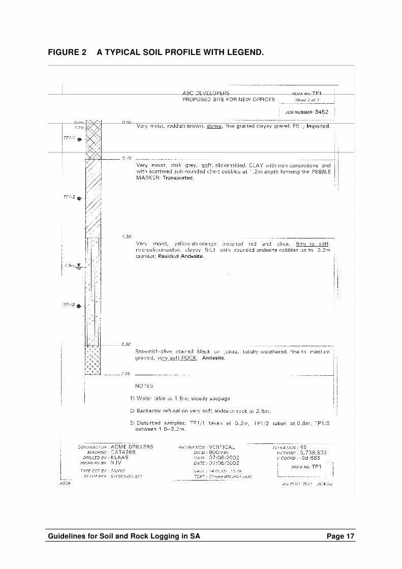
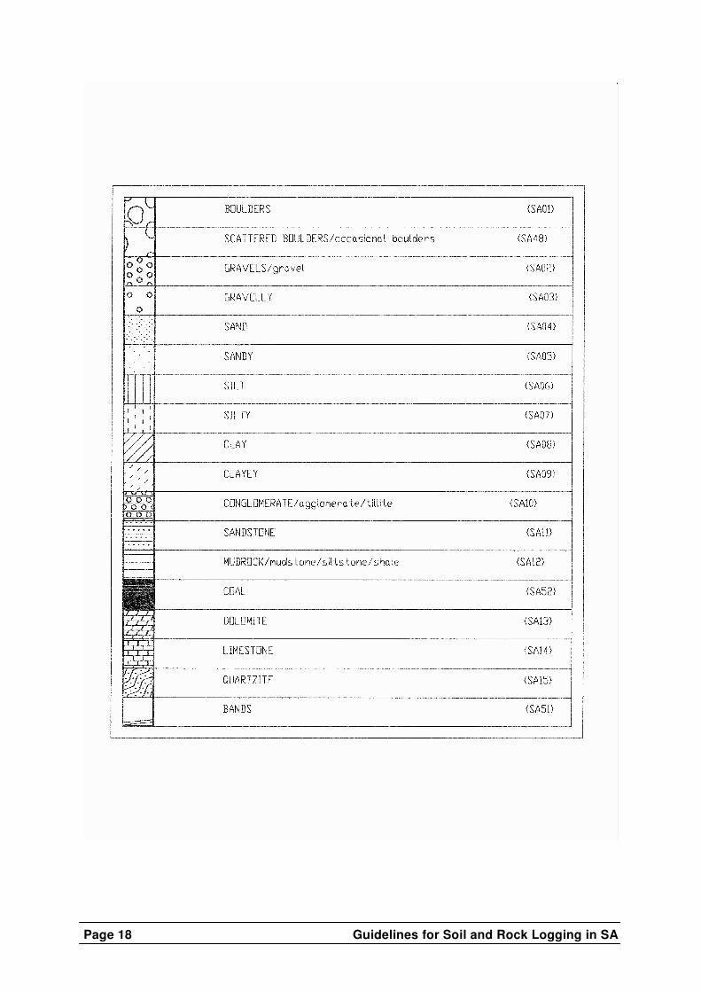
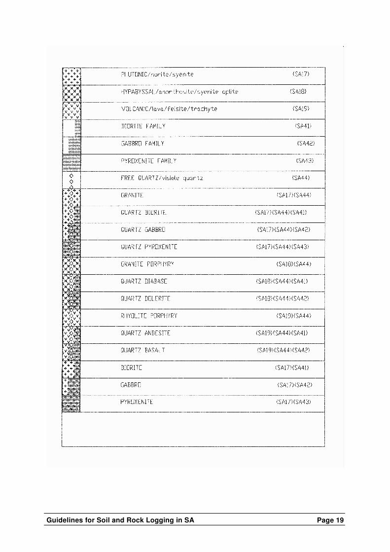
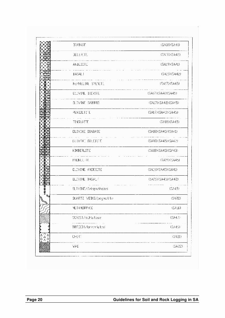
The soil profile is recorded alongside a symbolic section, drawn to scale, to allow for the correct perspective in the engineering assessment and for an easy visual comparison of a number of records from a site. Standard symbols to be used in the profile are given in the appendix. A typical profile sheet is shown in Figure 3.
Other information which must appear on each soil profile sheet is given in Table 7 and additional optional information is suggested in Table 8.
5. RECOMMENDED ADDITIONAL READING A’BEAR A (1987)
A technical note on the description of gravels for engineering purposes, Ground Profile No. 49, Jan 1987
BRIDGES E M (1970) World Soils. Cambridge University Press BRINK A B A (1985)
Engineering Geology of Southern Africa Vol 4, Building Publications, Pretoria
BRINK A B A, PARTRIDGE T C & WILLIAMS A A B (1982) Soil Survey for Engineering, Clarendon Press, Oxford BRITISH STANDARDS INSTITUTION (1981) BS 5930: Code of Practice for Site Investigations, BSI London CASAGRANDE A (1947)
Classification and identification of soil, Paper No 2351, Trans ASCE pp 901 – 991
DUMBLETON M J (1981) The British soil classification system for engineering purposes : Its development and relation to other comparable systems , Transport & Road Research Laboratory (TRRL) Lab Report 1030
Guidelines for Soil and Rock Logging in SA
Page 15
ICE London (1954) Civil Engineering Code of Practice No 4, Foundations
JENNINGS J E and BRINK A B A (1978) Application of geotechnics to the solution of engineering problems – essential preliminary steps to relate the structure to the soil which provides its support. Proc. Instn Civ. Engrs 64, 571-89 JENNINGS J E, BRINK A B A & WILLIAMS A A B (1973) Revised guide to soil profiling for civil engineering purposes in southern Africa, The Civil Engineer in South Africa, Jan 1973 Trans SAICE, Vol 15 No 1. MacVICAR et al. (1977) Soil classification in a binomial system for South Africa, Soil Irrigation & Research Institute, Pretoria NETTERBURG F (1980) Geology of southern African calcretes: 1. Terminology, description, macrofeatures, and classification, Trans of the Geol Soc of SA, Vol 83 No 2. NORBURY D R, CHILD G H & SPINK T W (1986) A critical review of Section 8 (BS 5930): soil and rock description, Site Investigation Practice: Assessing BS 5930 (Hawkins AB Editor), 20th Regional Meeting of the Engineering Group, Guildford, Geol Soc Engineering Geology Special Publication No 2 TERZAGHI K & PECK R B (1967) Soil mechanics in engineering practice (Second Edition), Wiley, New York WILLIAMS A A B (1971) Logging, sampling & in-situ testing, SAICE Lecture Programme, Course 8

Page 16 Guidelines for Soil and Rock Logging in SA
FIGURE 1 POSSIBLE COMBINATIONS OF ROCK, RESIDUAL SOILS, TRANSPORTED SOILS AND PEDOGENIC MATERIAL.
Guidelines for Soil and Rock Logging in SA
Page 17
FIGURE 2 A TYPICAL SOIL PROFILE WITH LEGEND.
Page 18 Guidelines for Soil and Rock Logging in SA
Guidelines for Soil and Rock Logging in SA
Page 19
Page 20 Guidelines for Soil and Rock Logging in SA

Guidelines for Soil and Rock Logging in SA
Page 21

Page 22 Guidelines for Soil and Rock Logging in SA
TABLE 1: SECONDARY COLOUR PATTERNS
TERM
DESCRIPTION
SPECKLED
Very small patches of colour <2 mm.
MOTTLED
Irregular patches of colour 2 – 6 mm.
BLOTCHED
Large irregular patches of colour 6 – 20 mm.
BANDED
Approximately parallel bands of varying colour.
STREAKED
Randomly orientated streaks of colour.
STAINED
Local colour variations: associated with discontinuity surfaces.
TABLE 2: CONSISTENCY OF GRANULAR SOILS
Consistency
Gravels and clean sands Generally free-draining
(cohensionless materials)
Typical
Dry Density (kg/m3)
Saturated
SPT Blow counts
N Very loose
Crumbles very easily when scraped with geological pick.
<1450
<4
Loose
Small resistance to penetration by sharp end of geological pick.
1451 to 1600
4 – 10
Medium dense
Considerable resistance to penetration by sharp end of geological pick.
1601 to 1750
11 – 30
Dense
Very high resistance to penetration of sharp end of geological pick; requires many blows of pick for excavation.
1751 to 1925
31 – 50
Very dense
High resistance to repeated blows of geological pick; requires power tools for excavation.
>1925
>50
Guidelines for Soil and Rock Logging in SA
Page 23
TABLE 3: CONSISTENCY OF COHESIVE SOILS
Consistency
Silts and clays and
combinations thereof with sand. Generally
slow draining (cohesive materials)
(����= 0)
Unconfined
Compressive Strength (kN/m2)
Saturated SPT Blow counts
Sensitive silts and clays
Saturated SPT Blow counts Insensitive
silts and clays
Very soft
Pick head can easily be pushed in to the shaft of handle; easily moulded by fingers.
<50
<2
<5
Soft
Easily penetrated by thumb; sharp end of pick can be pushed in 30 – 40 mm; moulded with some pressure.
50 to 125
2 – 4
5 – 10
Firm
Indented by thumb with effort; sharp end of pick can be pushed in up to 10 mm; very difficult to mould with fingers; can just be penetrated with an ordinary hand spade.
126 to 250
5 – 8
11 – 25
Stiff
Penetrated by thumb nail; slight indentation produced by pushing pick point into soil; cannot be moulded by fingers; requires hand pick for excavation.
251 to 500
9 – 15
26 – 50
Very stiff
Indented by thumb nail with difficulty; slight indentation produced by blow of pick point; requires power tools for excavation.
500 to 1000
16 – 20
51 – 80
Page 24 Guidelines for Soil and Rock Logging in SA
TABLE 4 STRUCTURE
TERM
IDENTIFICATION
INTACT
Structureless, no discontinuities identified.
FISSURED
Soil contains discontinuities which may be open or closed, stained or unstained and of variable origin.
SLICKENSIDED
This term qualifies other terms to describe discontinuity surfaces which are smooth or glossy and possibly striated.
SHATTERED
Very closely to extremely closely spaced continuities resulting in gravel sized soil fragments which are usually stiff to very stiff and difficult to break down.
MICRO-SHATTERED
As above, but sand-sized fragments.
STRATIFIED & LAMINATED & FOLIATED
These and other accepted geological terms may be used to describe sedimentary structures in transported soils and relict structures in residual soils.
PINHOLED
Pinhole-sized voids or pores (up to say 2 mm) which may require a hand lens to identify.
HONEYCOMBED
Similar to pinholed but voids and pores >2 mm; (pore size may be specified in mm).
MATRIX-SUPPORTED
Clasts supported by matrix.
CLAST-SUPPORTED
Clasts touching (matrix may or may not be present).
Guidelines for Soil and Rock Logging in SA
Page 25
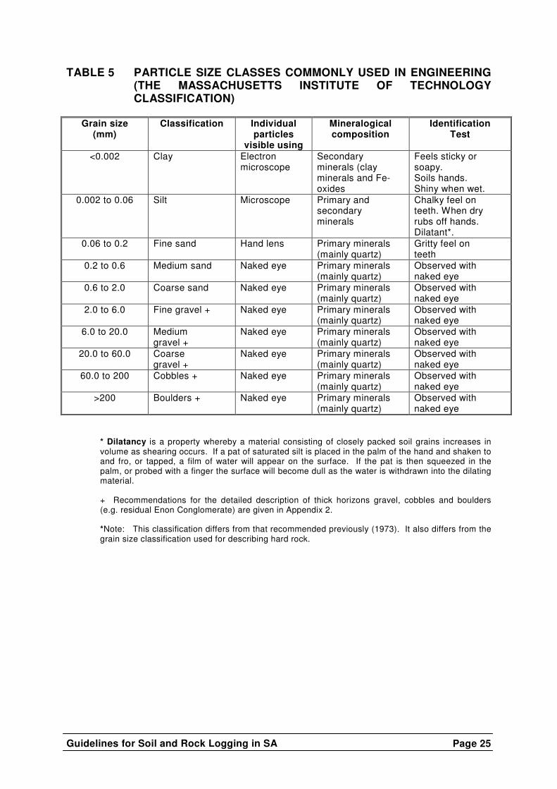
TABLE 5 PARTICLE SIZE CLASSES COMMONLY USED IN ENGINEERING (THE MASSACHUSETTS INSTITUTE OF TECHNOLOGY CLASSIFICATION)
Grain size
(mm) Classification Individual
particles visible using
Mineralogical composition
Identification Test
<0.002 Clay Electron microscope
Secondary minerals (clay minerals and Fe- oxides
Feels sticky or soapy. Soils hands. Shiny when wet.
0.002 to 0.06 Silt Microscope Primary and secondary minerals
Chalky feel on teeth. When dry rubs off hands. Dilatant*.
0.06 to 0.2 Fine sand Hand lens Primary minerals (mainly quartz)
Gritty feel on teeth
0.2 to 0.6 Medium sand Naked eye Primary minerals (mainly quartz)
Observed with naked eye
0.6 to 2.0 Coarse sand Naked eye Primary minerals (mainly quartz)
Observed with naked eye
2.0 to 6.0 Fine gravel + Naked eye Primary minerals (mainly quartz)
Observed with naked eye
6.0 to 20.0 Medium gravel +
Naked eye Primary minerals (mainly quartz)
Observed with naked eye
20.0 to 60.0 Coarse gravel +
Naked eye Primary minerals (mainly quartz)
Observed with naked eye
60.0 to 200 Cobbles + Naked eye Primary minerals (mainly quartz)
Observed with naked eye
>200 Boulders + Naked eye Primary minerals (mainly quartz)
Observed with naked eye
* Dilatancy is a property whereby a material consisting of closely packed soil grains increases in volume as shearing occurs. If a pat of saturated silt is placed in the palm of the hand and shaken to and fro, or tapped, a film of water will appear on the surface. If the pat is then squeezed in the palm, or probed with a finger the surface will become dull as the water is withdrawn into the dilating material.
+ Recommendations for the detailed description of thick horizons gravel, cobbles and boulders (e.g. residual Enon Conglomerate) are given in Appendix 2. *Note: This classification differs from that recommended previously (1973). It also differs from the grain size classification used for describing hard rock.
Page 26 Guidelines for Soil and Rock Logging in SA
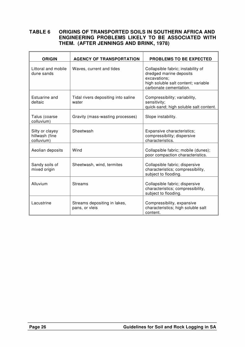
TABLE 6 ORIGINS OF TRANSPORTED SOILS IN SOUTHERN AFRICA AND ENGINEERING PROBLEMS LIKELY TO BE ASSOCIATED WITH THEM. (AFTER JENNINGS AND BRINK, 1978)
ORIGIN
AGENCY OF TRANSPORTATION
PROBLEMS TO BE EXPECTED Littoral and mobile dune sands
Waves, current and tides
Collapsible fabric; instability of dredged marine deposits excavations; high soluble salt content; variable carbonate cementation.
Estuarine and deltaic
Tidal rivers depositing into saline water
Compressibility; variability, sensitivity; quick-sand; high soluble salt content.
Talus (coarse colluvium)
Gravity (mass-wasting processes)
Slope instability.
Silty or clayey hillwash (fine colluvium)
Sheetwash
Expansive characteristics; compressibility; dispersive characteristics.
Aeolian deposits
Wind
Collapsible fabric; mobile (dunes); poor compaction characteristics.
Sandy soils of mixed origin
Sheetwash, wind, termites
Collapsible fabric; dispersive characteristics; compressibility, subject to flooding.
Alluvium
Streams
Collapsible fabric; dispersive characteristics; compressibility, subject to flooding.
Lacustrine
Streams depositing in lakes, pans, or vleis
Compressibility, expansive characteristics; high soluble salt content.
Guidelines for Soil and Rock Logging in SA
Page 27
Guide to Percussion Borehole Logging
Sec
tion
2
Page 28 Guidelines for Soil and Rock Logging in SA
CONTENTS Page
1. INTRODUCTION ................................................................................... 29 2. THE PERCUSSION BOREHOLE LOG ................................................... 29 2.1 Hole and casing diameters .......................................................................29 2.2 Chip size range ........................................................................................29 2.3 Water rest levels ......................................................................................29 2.4 Penetration time.......................................................................................30 2.5 Depth.......................................................................................................30 2.6 Legend ....................................................................................................30 2.7 Description...............................................................................................30 2.7.1 Soil composition ............................................................................31 2.7.2 Rock composition ..........................................................................33 2.7.3 Examples of descriptions ...............................................................33 3. THE DRILLER'S FIELD REPORT .......................................................... 34 4. APPENDIX 1 ......................................................................................... 35 5. APPENDIX 2 ......................................................................................... 36
TABLES Table 1 Grain size classification..................................................................... 32 Table 2 Degree of weathering ........................................................................ 32
Guidelines for Soil and Rock Logging in SA
Page 29
GUIDE TO PERCUSSION BOREHOLE LOGGING (as produced by the Geoterminology Workshop, 1990)
1. INTRODUCTION In order to avoid duplication, use has been made of the other standards, Guide to Soil Profiling for Civil Engineering Purposes and Guide to Core Logging for Civil Engineering Purposes which form part of this guide. The recommended descriptors in this document are applicable to most samples recovered from destructive drilling techniques.
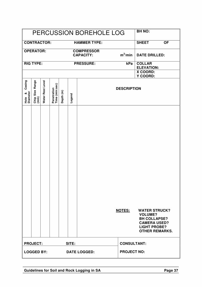
2. THE PERCUSSION BOREHOLE LOG The proposed percussion borehole log is included in Appendix 2 to this document. Entries on the borehole log are: 2.1 Hole and casing diameters
The borehole diameter/s should be noted as well as the internal diameter and depth to which casing of that specification has been installed.
2.2 Chip size range
The average size of fragments retrieved is indicated. The chip size will be influenced by the hardness of the rock and type of drilling bit used; generally the finer the chip size, the harder the formation.
2.3 Water rest levels
A number of water tables may be recognised in a borehole. These may include the permanent water table which shows little seasonal variation in elevation and the perched water table which lies above the permanent water table and which is usually subject to great seasonal variation. Perched water tables may develop on strata of low permeability during the rainy season and may disappear during the dry season. Water rest-levels should be read at least twenty-four hours after completion of the borehole and should be checked subsequently. It is recommended that permanent casing be installed in a number of boreholes on a site for long-term monitoring. In addition to noting the water rest-levels in the borehole, it is important to record where water was first encountered.

Page 30 Guidelines for Soil and Rock Logging in SA
2.4 Penetration time The penetration time should be recorded in minutes and seconds taken to penetrate each metre drilled. This time excludes flushing, cleaning and other delays. These figures are recorded in the appropriate column. The detail required in the execution of certain projects may necessitate noting this time over distances of less than one metre.
2.5 Depth
The depth below ground surface of the contacts between strata is recorded in this column.
2.6 Legend
Recommended symbols for use in the legend are given in the relevant Section: Guide to Soil Profiling for Civil Engineering Purposes.
2.7 Description
The major portion of the sample should be described first. For soil, the descriptors colour, soil texture, and origin are used. For rock the descriptors colour, weathering and rock type are used.
The subordinate portions of the sample are described using the aforementioned descriptors incorporating the following qualifications:
Traces - the subordinate amount is less than 10% of the total sample
Minor - the subordinate amount is between 10% and 30% of the total sample Abundant - the subordinate amount is between 30% and 50% of the total sample Equal Amounts - the major fractions occur in equal amounts. The moisture condition is generally not described as a number of factors may influence the final value, e.g. the addition of water during the drilling process, samples left exposed before being sealed, desiccation during the air-flushing process, etc.
In the description of the sample clear and unambiguous distinction should be made between fact and interpretation. Interpretations will usually contains words such as “possibly”, “probably” and ”interpreted as”, automatically clarifying the assessment being made.
Guidelines for Soil and Rock Logging in SA
Page 31
2.7.1 Soil component a) Colour
To obtain a standardised basis for judging the colour and to take cognisance of changes in colour with change in moisture content, it is recommended that the soil be described wet. (A small portion of the soil is taken in the palm of the hand and sufficient water is added to create a paste.)
Owing to the difficult and subjective nature of the task of assigning colour descriptions it is recommended that a colour chart be used. The Munsell colour chart or the Burland colour disc are recommended.
b) Soil Type
The soil type is described on the basis of grain size. The following descriptions are relevant:
Gravel
Gravel consists of fragments of rock between 200 mm and 2,0mm in size. The shape of the gravel particles should also be described as this assists the interpretation of origin:
well-rounded rounded sub-rounded sub-angular angular Sand
Sand consists of discrete particles between 2,0 mm and 0,06 mm in size. Except for the finer sizes the particles are visible to the naked eye (Table 1).
Silt
Silt consists of discrete particles which are smaller than 0,06 mm and larger than 0,002 mm in size. In general, silt particles are barely felt when rubbed with water on the palm of the hand.
Clays
Clays consist of particles smaller than 0,002 mm in size. In general, the particles are flaky and when rubbed on the palm of the hand with water have a soapy or greasy feel. There is no sensation of grittiness.
Most natural soils are a combination of one or more of the
above textures and in describing such a soil the adjective is

Page 32 Guidelines for Soil and Rock Logging in SA
used to denote the lesser constituent, e.g. a silty clay is a clay with some silt.
TABLE 1: GRAIN SIZE CLASSIFICATION
Description
Size in mm
Recognition
Equiv. Soil Type Very fine grained
<0,06
Individual grains cannot be seen with a hand lens
Clay & silts
Fine grained
0,06 – 0,2
Just visible a individual grains under hand lens
Fine sand
Medium grained
0,2 – 0,6
Grains clearly visible under hand lens, just visible to the naked eye
Medium sand
Coarse grained
0,6 – 2,0
Grains clearly visible to naked eye
Coarse sand
Very coarse grained
>2,0
Grains measurable
Gravel
TABLE 2: DEGREE OF WEATHERING
Diagnostic Feature / Description
Surface Characteristics
Unweathered Unchanged Slightly weathered Partial discolouration Medium weathered Partial to complete discolouration not
friable except poorly cemented rocks Highly weathered Friable and possibly pitted Completely weathered Resembles a soil
c) Origin
Where possible, the origin of the soil should be given, e.g. alluvium, residual dolomite, etc.
d) Contamination
With increasing depth and in uncased boreholes the risk of contamination increases. It may be necessary to adjust descriptions in accordance with sudden changes in penetration times.
Guidelines for Soil and Rock Logging in SA
Page 33
2.7.2 Rock component The fines component should be washed out prior to describing the coarse component.
a) Colour
To ensure that surfaces are representative of the colour of the rock material, only recently broken surfaces must be examined for the description. Surfaces altered by contaminants or surface abrasion should be avoided. Colour descriptions should be kept as simple as possible corresponding with those on an acceptable colour chart such as the Munsell Chart or Borland Colour Disk.
Where a rock chip displays a secondary colour this may be added to the predominant rock colour as an adjective, e.g. yellowish brown. Where significant, the colour could further be amplified by using the following descriptions for further distinction: very light, light, medium, dark, very dark.
b) Weathering
The state of weathering of the rock should be described in the broad categories defined in Table 2.
c) Rock name
The rock should be described both lithologically and stratigraphically, e.g. Lebowa Suite granite.
2.7.3 Examples of Descriptions a) Red, silty sand with minor white, highly weathered chert; chert
rubble.
b) Black, clayey silt (wad) with traces of grey, highly weathered chert; residual Lyttelton Formation dolomite. (Sample wet, possibly below water table).
c) Grey, highly weathered chert with abundant dark brown silty
clay, traces of black clayey silt (wad) and traces of brown, highly weathered dolomite; residual Monte Christo Formation dolomite.
d) White silty clay with an equal amount of light brown silty sand;
residual Ecca Group rocks. (Interpreted as a sequence of alternating mudrock and sandstone beds less than 0,5 m thick).
Page 34 Guidelines for Soil and Rock Logging in SA
3. THE DRILLER’S FIELD REPORT
The purpose of this sheet is for the written communication between the driller and the professional team. A simple report sheet is recommended for ease of recording operational and performance data. An example of such a sheet is given in Appendix 2. a) Hammer percussion
The two columns are provided so that the operator / observer can simply tick the appropriate column. The regular or irregular action of the hammer for the metre being drilled is recorded.
b) Water used and water struck
The depths at which water is used to retrieve samples are recorded using ticks. If ground water is encountered, the depth of the strike is recorded with a tick. The actual water-strike depth, if known, is recorded in the remarks column. The quantity should be ascertained and recorded.
c) Water level 24 hours after completion The borehole should be left open to permit this observation.
Plumbing to the bottom of the borehole is recommended in order to indicate if collapse has taken place.
Guidelines for Soil and Rock Logging in SA
Page 35
APPENDIX 1
Permanent Casing
If permanent casing is installed in the borehole the annulus between the borehole wall and the casing should be grouted, a concrete collar cast at surface around the casing to secure and seal the head of the borehole, and a suitable lockable cap secured.
Backfilling of borehole
If not required for monitoring, the borehole should be backfilled with suitable spoil material. Suitable additional fill material must be used to ensure that the entire volume of the borehole is adequately backfilled. The addition of cement to the backfill material is strongly recommended.
Sealing of borehole
The upper 5 m of the borehole should be backfilled with concrete. A concrete slab 1 m square should be cast over the backfilled borehole. This slab will prevent water ingress and the possible development of a sinkhole in karst terrain.
Page 36 Guidelines for Soil and Rock Logging in SA
APPENDIX 2
Percussion Borehole Log
Driller’s Field Report
Guidelines for Soil and Rock Logging in SA
Page 37
PERCUSSION BOREHOLE LOG
BH NO:
CONTRACTOR: HAMMER TYPE:
SHEET OF
OPERATOR: COMPRESSOR CAPACITY: m3/min
DATE DRILLED:
RIG TYPE: PRESSURE: kPa COLLAR ELEVATION:
X COORD: Y COORD:
Hol
e &
C
asin
g D
iam
eter
Chi
p S
ize
Ran
ge
(mm
)
Wat
er R
est
Leve
l
Pen
etra
tion
T
ime
(min
:sec
)
Dep
th (
m)
Leg
end
DESCRIPTION
NOTES: WATER STRUCK? VOLUME? BH COLLAPSE? CAMERA USED? LIGHT PROBE? OTHER REMARKS.
PROJECT: SITE: LOGGED BY: DATE LOGGED:
CONSULTANT: PROJECT NO:

Page 38 Guidelines for Soil and Rock Logging in SA
CONTRACTOR: BOREHOLE NO:
DRILLER’S FIELD REPORT PROJECT NO:
PROJECT:
DATE STARTED:
SITE:
DATE COMPLETED:
CLIENT:
COMPRESSOR DETAILS
MACHINE:
CAPACITY: m3 / min
HAMMER TYPE:
PRESSURE: kPa
Penetration
Hammer
Percussion
Water
Dep
th (
m)
Tim
e
(m
in:s
ec)
Hol
e D
iam
eter
(m
m)
Cas
ing
Inst
alle
d
(dia
met
er m
m)
RE
G
IRR
EG
Use
d
Str
uck
(
m)
No
Air
Ret
urn
No
Sam
ple
Ret
urn
REMARKS*
WATER LEVEL 24 HOURS AFTER COMPLETION: m DATE: PERMANENT CASING: BACKFILLING: CAPPED: SIGNATURE:
Guidelines for Soil and Rock Logging in SA
Page 39
SECTION 3
Guide to Core Logging for Civil Engineering Purposes
Sec
tion
3
Page 40 Guidelines for Soil and Rock Logging in SA
CONTENTS Page
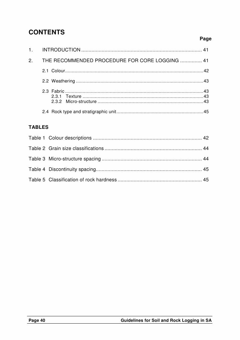
1. INTRODUCTION ................................................................................... 41 2. THE RECOMMENDED PROCEDURE FOR CORE LOGGING ............... 41 2.1 Colour......................................................................................................42 2.2 Weathering ..............................................................................................43 2.3 Fabric ......................................................................................................43 2.3.1 Texture .........................................................................................43 2.3.2 Micro-structure ..............................................................................43 2.4 Rock type and stratigraphic unit ................................................................45 TABLES Table 1 Colour descriptions ........................................................................... 42 Table 2 Grain size classifications ................................................................... 44 Table 3 Micro-structure spacing ..................................................................... 44 Table 4 Discontinuity spacing......................................................................... 45 Table 5 Classification of rock hardness .......................................................... 45
Guidelines for Soil and Rock Logging in SA
Page 41
GUIDE TO CORE LOGGING FOR CIVIL ENGINEERING PURPOSES (as revised by the Geoterminology Workshop, 1990)
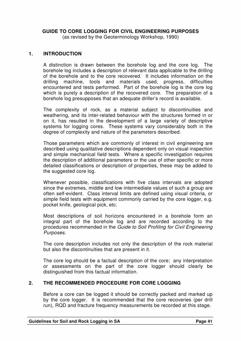
1. INTRODUCTION
A distinction is drawn between the borehole log and the core log. The borehole log includes a description of relevant data applicable to the drilling of the borehole and to the core recovered. It includes information on the drilling machine, tools and materials used, progress, difficulties encountered and tests performed. Part of the borehole log is the core log which is purely a description of the recovered core. The preparation of a borehole log presupposes that an adequate driller’s record is available.
The complexity of rock, as a material subject to discontinuities and weathering, and its inter-related behaviour with the structures formed in or on it, has resulted in the development of a large variety of descriptive systems for logging cores. These systems vary considerably both in the degree of complexity and nature of the parameters described.
Those parameters which are commonly of interest in civil engineering are described using qualitative descriptions dependent only on visual inspection and simple mechanical field tests. Where a specific investigation requires the description of additional parameters or the use of other specific or more detailed classifications or description of properties, these may be added to the suggested core log.
Whenever possible, classifications with five class intervals are adopted since the extremes, middle and low intermediate values of such a group are often self-evident. Class interval limits are defined using visual criteria, or simple field tests with equipment commonly carried by the core logger, e.g. pocket knife, geological pick, etc.
Most descriptions of soil horizons encountered in a borehole form an integral part of the borehole log and are recorded according to the procedures recommended in the Guide to Soil Profiling for Civil Engineering Purposes.
The core description includes not only the description of the rock material but also the discontinuities that are present in it.
The core log should be a factual description of the core; any interpretation or assessments on the part of the core logger should clearly be distinguished from this factual information.
2. THE RECOMMENDED PROCEDURE FOR CORE LOGGING
Before a core can be logged it should be correctly packed and marked up by the core logger. It is recommended that the core recoveries (per drill run), RQD and fracture frequency measurements be recorded at this stage.

Page 42 Guidelines for Soil and Rock Logging in SA
In logging core six descriptors (CWFDHR) are recommended:
• Colour • Weathering • Fabric • Discontinuities • Hardness • Rock Name
2.1 COLOUR Since colour varies with moisture content it is recommended that core should be wet when described. Where descriptions are made of core at other moisture contents this should be described in accordance with the guide to soil profiling as dry, slightly moist, moist, wet, very wet.
Colour descriptions should be kept as simple as possible and the actual terms used should, where possible, correspond with those on accepted colour charts such as the Munsell colour chart or the Burland colour disc.
The rock colour is that which is predominant, e.g. brown, green, red, pink, khaki. Where a secondary colour is also evident this can be included in the description as an adjective, e.g. reddish brown. The colour may be further amplified by using the following descriptions:
very light, light, dark, very dark, e.g. dark reddish brown.
The colour of features should be described separately; these usually have a characteristic pattern which may be described by one or more of the following terms: TABLE 1: COLOUR DESCRIPSTIONS
TERM DESCRIPTION SPECKLED Very small patches of colour <2 mm MOTTLED Irregular patches of colour 2 – 6 mm BLOTCHED Large irregular patches of colour 6 – 20 mm BANDED Approximately parallel bands of varying colour* STREAKED Randomly orientated streaks of colour* STAINED Local colour variations associated with discontinuity surfaces
* Describe thickness using bedding thickness criteria (e.g. thickly banded, thinly streaked, etc)
Guidelines for Soil and Rock Logging in SA
Page 43
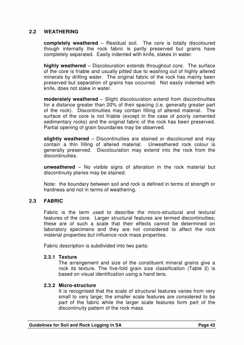
2.2 WEATHERING completely weathered – Residual soil. The core is totally discoloured though internally the rock fabric is partly preserved but grains have completely separated. Easily indented with knife, slakes in water.
highly weathered – Discolouration extends throughout core. The surface of the core is friable and usually pitted due to washing out of highly altered minerals by drilling water. The original fabric of the rock has mainly been preserved but separation of grains has occurred. Not easily indented with knife, does not slake in water.
moderately weathered – Slight discolouration extend from discontinuities for a distance greater than 20% of their spacing (i.e. generally greater part of the rock). Discontinuities may contain filling of altered material. The surface of the core is not friable (except in the case of poorly cemented sedimentary rocks) and the original fabric of the rock has been preserved. Partial opening of grain boundaries may be observed.
slightly weathered – Discontinuities are stained or discoloured and may contain a thin filling of altered material. Unweathered rock colour is generally preserved. Discolouration may extend into the rock from the discontinuities.
unweathered – No visible signs of alteration in the rock material but discontinuity planes may be stained.
Note: the boundary between soil and rock is defined in terms of strength or hardness and not in terms of weathering.
2.3 FABRIC
Fabric is the term used to describe the micro-structural and textural features of the core. Larger structural features are termed discontinuities; these are of such a scale that their effects cannot be determined on laboratory specimens and they are not considered to affect the rock material properties but influence rock mass properties.
Fabric description is subdivided into two parts: 2.3.1 Texture
The arrangement and size of the constituent mineral grains give a rock its texture. The five-fold grain size classification (Table 2) is based on visual identification using a hand lens.
2.3.2 Micro-structure It is recognised that the scale of structural features varies from very small to very large; the smaller scale features are considered to be part of the fabric while the larger scale features form part of the discontinuity pattern of the rock mass.

Page 44 Guidelines for Soil and Rock Logging in SA
The descriptive terminology is indicative of rock type e.g. laminated, bedded, massive (sedimentary), foliated, schistose, banded, gneissic, cleaved (metamorphic) flow-banded, foliated, massive (igneous)
TABLE 2: GRAIN-SIZE CLASSIFICATION
DESCRIPTION SIZE (mm) IDENTIFICATION
Very fine grained
< 0,2
Individual grains cannot be seen with a hand lens
Fine grained
0,2 – 0,6
Visible as individual grains under hand lens
Medium grained
0,6 – 2,0
Grains clearly visible under hand lens, just visible to the naked eye
Coarse grained
2,0 – 6,0
Grains clearly visible to the naked eye
Very coarse grained
>6,0
Grains measurable
TABLE 3: MICRO-STRUCTURE SPACING
Very intensely
<6 mm
Intensely (1)
6 – 20 mm
Very thinly (2)
20 – 60 mm
Thinly (2)
60 mm – 0,2 m
Medium (2)
0,2 – 0,6 m
Thickly (2)
0,6 m – 2,0 m
Very thickly (2)
>2,0 m
(1) foliated / laminated / cleaved (2) foliated / bedded / banded
Consider also: inclusions, fossils, graded bedding, cross-bedding, slump-structure, deformation, amygdales, etc. Composition and shape of inclusions should be recorded.
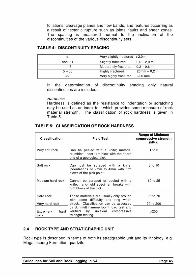
Discontinuity spacing
A discontinuity is defined as any surface across which some property for a rock mass is discontinuous. This includes fractures, bedding planes and joints. Discontinuities include two major categories: features characteristic of the origin of the rock such as bedding,
Guidelines for Soil and Rock Logging in SA
Page 45
foliations, cleavage planes and flow bands, and features occurring as a result of tectonic rupture such as joints, faults and shear zones. The spacing is measured normal to the inclination of the discontinuities of the various discontinuity sets.
TABLE 4: DISCONTINUITY SPACING
<1 Very slightly fractured >2,0m
about 1 Slightly fractured 0,6 – 2,0 m 1 – 5 Moderately fractured 0,2 – 0,6 m
5 – 50 Highly fractured 20mm – 0,2 m >50 Very highly fractured <20 mm
In the determination of discontinuity spacing only natural discontinuities are included.
Hardness Hardness is defined as the resistance to indentation or scratching may be used as an index test which provides some measure of rock material strength. The classification of rock hardness is given in Table 5.
TABLE 5: CLASSIFICATION OF ROCK HARDNESS
Classification
Field Test
Range of Minimum compressive strength
(MPa) Very soft rock
Can be peeled with a knife; material crumbles under firm blow with the sharp end of a geological pick.
1 to 3
Soft rock
Can just be scraped with a knife; indentations of 2mm to 4mm with firm blows of the pick point.
3 to 10
Medium hard rock
Cannot be scraped or peeled with a knife; hand-held specimen breaks with firm blows of the pick.
10 to 25
Hard rock
25 to 70
Very hard rock
70 to 200
Extremely hard rock
These materials are usually only broken with some difficulty and ring when struck. Classification can be assessed by Schmidt hammer/point load test and verified by uniaxial compressive strength testing.
>200
2.4 ROCK TYPE AND STRATIGRAPHIC UNIT Rock type is described in terms of both its stratigraphic unit and its lithology, e.g. Magaliesberg Formation quartzite.

![arXiv:1804.07991v4 [physics.geo-ph] 4 Nov 2018 · 2018. 11. 6. · Airborne EM problems over a 1D layered earth or borehole-logging applications fall into this category; in these](https://img.pdfslide.tips/doc/110x75/5fdaabf50fe3965d6b29df94/arxiv180407991v4-4-nov-2018-2018-11-6-airborne-em-problems-over-a-1d.jpg)