Embed Size (px)
Citation preview
7/27/2019 2000 Matsui
http://slidepdf.com/reader/full/2000-matsui 1/8
O
rthodontic treatment is often achieved more effi-
ciently when the tipping of teeth is minimized.By definition, a force with a line of action passing
through the center of resistance (CR) of a tooth pro-
duces pure translation without rotation of the tooth.1
Further, the tooth subjected to such a force is more
resistant to movement.2 Therefore, tipping will be less
for forces directed near the CR. For normal conditions
of periodontal tissues, the CR for a single root tooth
exists two thirds of the distance from the alveolar
crest to the apex.3 If a force were applied with a line
of action passing through the CR, the tooth would
undergo bodily movement. During canine retraction,
tipping can be eliminated by applying a force and
moment combination to the crown that produces aresultant force that passes through the CR. In the case
of a tooth with multiple roots, such as a maxillary first
molar, the CR is located near the furcation. With these
teeth, bodily movement may be obtained by using a
headgear appliance with the outer bow adjusted so
that the resultant force passes through the furcation
area. Therefore, the orthodontist always considers the
relationship between the location of the CR and the
applied force vector.
A number of investigators have reported on the
location of the CR for single root teeth, determined byvarious theoretical and experimental methods. For
example, Haack and Weinstein3 considered the effects
of forces on the motion of a 2-dimensional model of an
incisor. They concluded that pure translation was
obtained by a single force passing through the CR, or
by a combination of a single force and an appropriate
moment applied at the bracket. Burstone4 reported that
the CR was located at 33% of the distance of the root
length apical to the alveolar crest for an idealized upper
incisor. Using a holographic measuring technique, Bur-
stone and Pryputniewicz5,6 found that the CR of the
upper incisor was located slightly more occlusal when
compared with the theoretical one.2 More recently,Tanne et al7 used a 3-dimensional finite element analy-
sis to determine displacements of teeth with various
root lengths and alveolar bone heights conditions. They
concluded the location of the CR shifted apically as the
alveolar bone height was reduced.
In the case of maxillary molars, bodily movement
was obtained when the traction line of a cervical head-
gear passed through the trifurcation areas. It was con-
cluded that the CR of the upper first molar was located
at this area.8 Burstone et al9 stated that the CR of
mandibular molars was between 30% and 40% of the
distance from the alveolar crest to the apex. Pederson et
al10 also studied mandibular molars, by using displace-
ment transducers on human autopsy material. They
described the relationship between a force system and
the resulting tooth movement by the position of the
center of rotation, the CR, and the angle of rotation. It
was concluded that the CR location depended on tooth
anatomy and the shape and amount of bony support.
On the other hand, significantly less attention has
been given to the CR of a segmented arch. Dermaut and
aAssistant Professor, Department of Orthodontics, School of Dentistry, Meikai
University, Saitama, Japan.bProfessor and Chairman, Section of Biomaterials Science, School of Dentistry,
University of California, Los Angeles.cProfessor Emeritus, Section of Orthodontics, School of Dentistry, University
of California, Los Angeles.dProfessor Emeritus, Department of Orthodontics, School of Dentistry, Meikai
University, Saitama, Japan.
Reprint requests to: Shigeyuki Matsui, Department of Orthodontics, School of
Dentistry, Meikai University, 1-1 Keyakidai, Sakado City, Saitama, Japan 350-
02; e-mail, [email protected]
Submitted, October 1998; Revised and accepted, August 1999.
Copyright © 2000 by the American Association of Orthodontists
0089-5406/2000/$12.00 + 0 8/1/103774
doi:10.1067/mod.2000.103774
171
ORIGINAL ARTICLE
Center of resistance of anterior arch segment
Shigeyuki Matsui, DDS, PhD,a A. A. Caputo, PhD,b Spiro J Chaconas, DDS, MS,c and
Hiroshi Kiyomura, DDS, DMScd
Saitama, Japan, and Los Angeles, Calif
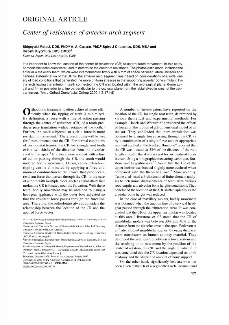
It is important to know the location of the center of resistance (CR) to control tooth movement. In this study,
photoelastic techniques were used to determine the center of resistance. The photoelastic model included the
anterior 4 maxillary teeth, which were interconnected firmly with 6 mm of space between lateral incisors and
canines. Determination of the CR for the anterior arch segment was based on considerations of a wide vari-
ety of load conditions that generated the more uniform stresses in the supporting alveolar bone simulant. For
the arch having the anterior 4 teeth connected, the CR was located within the mid-sagittal plane, 6-mm api-
cal and 4-mm posterior to a line perpendicular to the occlusal plane from the labial alveolar crest of the cen-
tral incisor. (Am J Orthod Dentofacial Orthop 2000;118:171-8)
7/27/2019 2000 Matsui
http://slidepdf.com/reader/full/2000-matsui 2/8
172 Matsui et al American Journal of Orthodontics and Dentofacial Orthopedics
August 2000
Bulcke11 used the laser reflection technique and holo-
graphic interferometry in testing 2 types of segmented
arches on a macerated human skull. When the 6 ante-
rior teeth were incorporated in a sectional wire, they
found that the CR was located more to the distal side of the canines; however, it was more difficult to define the
CR of the 4 incisors. They concluded it was situated
just distal to the lateral incisors.
Pedersen et al12 also determined the location of the
CR of various consolidated units of maxillary anterior
teeth on human autopsy material by means of a dis-
placement measuring device. The units studied con-
sisted of 2 central incisors, 4 incisors, and 6 anterior
teeth, and they described the changes of the location of
the CR for each of the arch segment units. The results
of these studies are not in complete agreement on the
location of the CR in segmented arch units.
None of these techniques makes any estimations of
internal stress within the supporting structures around
the teeth that would lead to biologic alterations. When
the induced stresses are uniform, biologic changes take
place that lead, in time, to translational motion.13 In
this study, the quasi-3-dimensional photoelastic tech-
nique was used.14 This modeling technique allows for
visualization of internal stresses developed within the
model around the loaded teeth. By rotating the model,
visual access to stresses in various locations, including
mediolateral directions, is enhanced.
Therefore, it was the purpose of this investigation todetermine the CR of a maxillary anterior arch segment
based on observations of stress distributions around teeth
in simulated periodontal tissues of a photoelastic model.
MATERIAL AND METHODS
Photoelastic Materials and Frame Work
A compound photoelastic 3-dimensional model of a
maxilla was used in this study. Impressions were made
of a maxilla and maxillary teeth by using a silicone mold
material. Different plastic simulants were used to fabri-
cate the individual components of the model. As shown
in Table I, PL-1 (Photolastic Division, Measurements
Group, Raleigh, NC) was used for the teeth, PL-2 (Pho-tolastic Division) for alveolar bone, and Solithane
(Uniroyal Chemical Co, Inc, Middlebury, CT) for the
periodontal membrane.14-16 After being assembled, the
model was fixed firmly, with epoxy resin, to a support-
ing plate at the zygomatic and frontal processes.
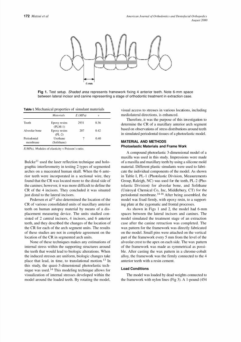
As shown in Figs 1 and 2, the model had 6-mm
spaces between the lateral incisors and canines. The
model simulated the treatment stage of an extraction
case after the canine retraction was completed. The
wax pattern for the framework was directly fabricated
on the model. Small pins were attached on the vertical
part of the framework every 5 mm from the level of the
alveolar crest to the apex on each side. The wax pattern
of the framework was made as symmetrical as possi-
ble. After casting the wax pattern in a chrome-cobalt
alloy, the framework was the firmly connected to the 4
anterior teeth with a resin cement.
Load Conditions
The model was loaded by dead weights connected to
the framework with nylon lines (Fig 3). A 1-pound (454
Table I. Mechanical properties of simulant materials
Materials E (MPa) v
Tooth Epoxy resins 2931 0.36
(PLM-1)
Alveolar bone Epoxy resins 207 0.42
(PL-2)
Periodontal Urethane 7 0.40
membrane (Solithane)
E(MPa), M odules of elasticity v Poisson’s ratio.
Fig 1. Test setup. Shaded area represents framework fixing 4 anterior teeth. Note 6-mm space
between lateral incisor and canine representing a stage of orthodontic treatment in extraction case.

7/27/2019 2000 Matsui
http://slidepdf.com/reader/full/2000-matsui 3/8
American Journal of Orthodontics and Dentofacial Orthopedics Matsui et al 173Volume 118 , Number 2
gm) weight was applied to each side of the arch. Various
directions of pull were obtained by altering the position
of pulleys affixed posterior to the model, as shown in Fig
3, and the location of the hooks to which the lines were
connected. Loads were applied to the framework in a
posterior direction at various angles to the occlusal
plane. These force directions were obtained by adjusting
the position of the line on the framework from A to D,
and by changing the pulley location from 2.0 to 4.0. Fig
3 A, shows an example of direction 2.0-A, which means
that the position of the line on the frame is A, and pulley
location is 2.0. Vertical loads also were applied perpen-
dicular to the occlusal plane at 2-mm increments from
the anterior alveolar ridge of the central incisor (Fig 3 B).
Photoelastic Experiment
All loading was performed in the field of a circu-
lar polariscope, with the model immersed in a tank of
mineral oil to facilitate isochromatic fringe observa-
tion (Fig 4). These isochromatic fringes are distrib-
uted 3-dimensionally in response to the intensity of
internal stress. Stress is high in an area when many
lines are seen and concentrated when distance
between fringes is small. Presentation of the photoe-
lastic data was facilitated by schematic representa-
tions of the stress distributions. In these diagrams,
areas of high stress concentration are denoted by the
darkest shading and lower stresses are shown with
light shading. Further, since there was almost com-
Fig 2. Photoelastic model used: (a) anterior segment; (b) chromium-cobalt frame; (c) pulley.
Fig 3. Diagrammatic representation of directions of pull applied to arch segments. A, Distal load.The
arrrow shows an example of direction of pull 2.0-A. B, Vertical load.
A B

7/27/2019 2000 Matsui
http://slidepdf.com/reader/full/2000-matsui 4/8
174 Matsui et al American Journal of Orthodontics and Dentofacial Orthopedics
August 2000
In general, the various force vectors applied to the
framework produced different degrees of lingual
crown tipping, as manifested by nonuniform fringe
patterns within the periodontal membranes and alve-
olar bone simulants. Fig 5 shows the comparison
of the stress distributions for 2.0-A loading (distal,
parallel to the occlusal plane) on the left, with load-
ing 2.0-D (distal, toward the occlusal plane) on the
right. Load 2.0-A concentrated stress at both sides of
the central incisor root, being higher on the distal.
Stress also was localized distally along the lateral
incisor and the mesial part of the canine root. These
high-stress areas were toward the crestal one-third of
the roots. This stress distribution reflects lingual
crown tipping.
plete symmetry of the stress fields about the midline,
only the right-side data are presented.
From all of the test conditions, the load was sought
that produced a relatively uniform stress distribution
pattern in order to determine the general area of the
CR. Because of the symmetry of the model and the
applied loads, the location of the CR can be expected to
lie in the mid-sagittal plane.
RESULTS
Examination of the unloaded model in the circular
polariscope revealed an almost stress-free condition
(less than one-half fringe order maximum). Conse-
quently, the stress patterns observed on load applica-
tion were due to the effects of the applied loads.
Fig 4. Circular polariscope arrangement for visualization of isochromatic fringes. LS, Light source;
D, diffuser; P, polarizer; M, model; Q, quarter-wave plate.
Fig 5. A comparison of stresses generated by 2 pull directions.The width of the periodontal ligaments
in the diagram is exaggerated to facilitate presentation of fringes. Note nonuniform stress distributions.

7/27/2019 2000 Matsui
http://slidepdf.com/reader/full/2000-matsui 5/8
American Journal of Orthodontics and Dentofacial Orthopedics Matsui et al 175Volume 118 , Number 2
A different distribution resulted from 2.0-D loading.
Here, the highest stress concentrations occur along the
middle half of the distal aspect of the root of the central
incisor. This distribution is indicative of labial crown tip-
ping and is in contrast to the lingual effects of load 2.0-A.
A relatively uniform distribution pattern was
observed when the position of the pulleys was 4.0 and
the lines for loading were attached between B and C
of the framework, as shown in Fig 6. This uniform
stress distribution indicates that the vertical location
of the CR exists close to this axis.
Fig 7 shows the stress distributions resulting from
forces applied vertical to the occlusal plane. When a
load α was applied at the anterior region (Fig 7 A),
Fig 6. Stresses resulting from 4.0-BC direction of pull. Note uniformity of stress distribution.
Fig 7. Comparison of stress distributions of different locations of vertical pull. A, Load α; B, load γ ;
C, load ε; D, location of vertical directions of pull.
A B
C D
7/27/2019 2000 Matsui
http://slidepdf.com/reader/full/2000-matsui 6/8
176 Matsui et al American Journal of Orthodontics and Dentofacial Orthopedics
August 2000
stress concentrations were found at the distal parts of
the roots of the anterior teeth. When a load ε was
applied at the posterior part of the anterior segment
(Fig 7, C ), higher stress concentrations were observed
at the distal parts of the roots of the lateral incisors and
within the alveolar crest between laterals and canines.
The stresses generated by load γ midway between α
and ε are shown in Fig 7, B. This load produced high
stresses uniformly distributed to the middle one third of
the distal aspect of the central incisor root, the distal of
the lateral incisor, and to the distal part of the canine.
Therefore, the horizontal location of the CR exists
close to this direction of pull.
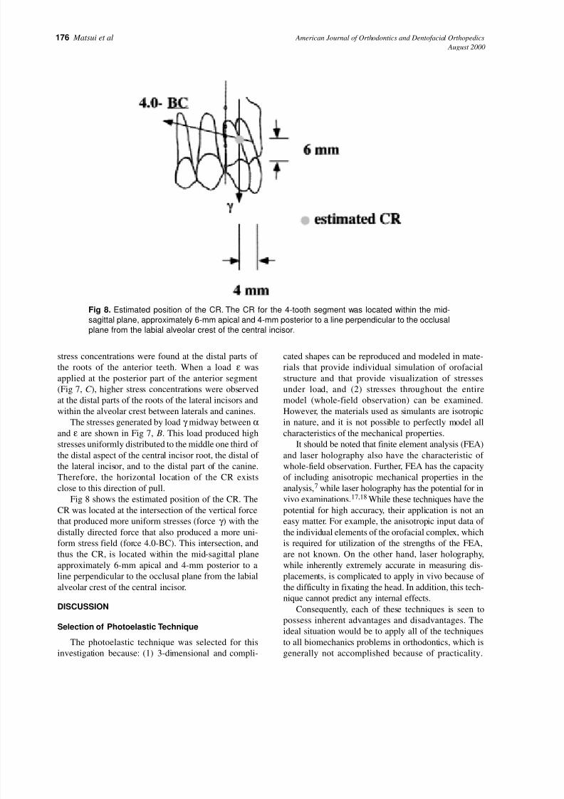
Fig 8 shows the estimated position of the CR. The
CR was located at the intersection of the vertical force
that produced more uniform stresses (force γ ) with the
distally directed force that also produced a more uni-
form stress field (force 4.0-BC). This intersection, and
thus the CR, is located within the mid-sagittal plane
approximately 6-mm apical and 4-mm posterior to a
line perpendicular to the occlusal plane from the labial
alveolar crest of the central incisor.
DISCUSSION
Selection of Photoelastic Technique
The photoelastic technique was selected for this
investigation because: (1) 3-dimensional and compli-
cated shapes can be reproduced and modeled in mate-
rials that provide individual simulation of orofacial
structure and that provide visualization of stresses
under load, and (2) stresses throughout the entire
model (whole-field observation) can be examined.
However, the materials used as simulants are isotropic
in nature, and it is not possible to perfectly model allcharacteristics of the mechanical properties.
It should be noted that finite element analysis (FEA)
and laser holography also have the characteristic of
whole-field observation. Further, FEA has the capacity
of including anisotropic mechanical properties in the
analysis,7 while laser holography has the potential for in
vivo examinations.17,18 While these techniques have the
potential for high accuracy, their application is not an
easy matter. For example, the anisotropic input data of
the individual elements of the orofacial complex, which
is required for utilization of the strengths of the FEA,
are not known. On the other hand, laser holography,
while inherently extremely accurate in measuring dis-
placements, is complicated to apply in vivo because of
the difficulty in fixating the head. In addition, this tech-
nique cannot predict any internal effects.
Consequently, each of these techniques is seen to
possess inherent advantages and disadvantages. The
ideal situation would be to apply all of the techniques
to all biomechanics problems in orthodontics, which is
generally not accomplished because of practicality.
Fig 8. Estimated position of the CR. The CR for the 4-tooth segment was located within the mid-
sagittal plane, approximately 6-mm apical and 4-mm posterior to a line perpendicular to the occlusal
plane from the labial alveolar crest of the central incisor.
7/27/2019 2000 Matsui
http://slidepdf.com/reader/full/2000-matsui 7/8
American Journal of Orthodontics and Dentofacial Orthopedics Matsui et al 177Volume 118 , Number 2
Photoelasticity has had a long history of applications indentistry and has been shown to be predictive of many
clinically observed phenomena.
CR Determination and Location
In this study, a photoelastic technique was used to
determine the CR of a maxillary anterior arch segment
based on observations of stress distributions around teeth
in simulated periodontal tissues of a photoelastic model.
The location of the CR was determined by observing
isochromatic patterns. If an applied force produces a rel-
atively uniform fringe pattern in the periodontal mem-
brane and surrounding tissues, the force must pass close
to the CR. Therefore, the CR was established as the pointof intersection of the lines of action of the forces, both
perpendicular and inclined to the occlusal plane, that
produced uniform stress distributions around the teeth. A
pure translation of teeth would occur if the stresses
around the periodontal tissues and surrounding bones
were uniform.13 The CR is located within the mid-sagit-
tal plane, approximately 6-mm apical and 4-mm poste-
rior to a line perpendicular to the occlusal plane from the
labial alveolar crest of the central incisor.
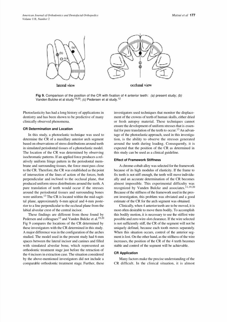
These findings are different from those found by
Pedersen and colleagues12 and Vanden Bulcke et al.19,20
Fig 9 compares the locations of the CR determined by
these investigators with the CR determined in this study.
A major difference was in the configuration of the arches
studied. The model used in the present study had 6-mm
spaces between the lateral incisor and canines and filled
with simulated alveolar bone, which represented an
orthodontic treatment stage just before the retraction of
the 4 incisors in extraction case. The situation considered
by the above-mentioned investigators did not include a
comparable orthodontic treatment stage. Further, these
investigators used techniques that monitor the displace-ment of the crowns of teeth of human skulls, either dried
or fresh autopsy material. These techniques cannot
ensure the development of uniform stresses that is essen-
tial for pure translation of the teeth to occur.13 An advan-
tage of the photoelastic approach, used in this investiga-
tion, is the ability to observe the stresses generated
around the teeth during loading. Consequently, it is
expected that the position of the CR as determined in
this study can be used as a clinical guideline.
Effect of Framework Stiffness
A chrome-cobalt alloy was selected for the framework
because of its high modulus of elasticity. If the frame tofix teeth is not stiff enough, the teeth will move individu-
ally and an accurate determination of the CR becomes
almost impossible. This experimental difficulty was
recognized by Vanden Bulcke and associates.11,19,20
Because of the stiffness of the framework used in the pres-
ent investigation, this problem was obviated and a good
estimate of the CR for the arch segment was obtained.
Clinically, when 4 anterior teeth are to be moved, it is
most often desirable to move them bodily. To accomplish
this bodily motion, it is necessary to use the stiffest wire
possible and zero wire-slot clearance. If the wire selected
is not sufficiently stiff, the CR of the segment will not be
uniquely defined, because each tooth moves separately.
When this situation occurs, control of the anterior seg-
ment is lost. On the other hand, as the stiffness of the wire
increases, the position of the CR of the 4 teeth becomes
stable and control of the segment will be achievable.
CR Application
Many factors make the precise understanding of the
CR difficult. In the clinical situation, it is almost
Fig 9. Comparison of the position of the CR with fixation of 4 anterior teeth: (a) present study; (b)
Vanden Bulcke et al study19,20; (c) Pedersen et al study.12
7/27/2019 2000 Matsui
http://slidepdf.com/reader/full/2000-matsui 8/8
178 Matsui et al American Journal of Orthodontics and Dentofacial Orthopedics
August 2000
impossible to keep the direction and the amount of
applied force constant. In addition, factors that alter the
position of the CR of 4 anterior teeth are the shape of
surrounding bone, root morphology, position of each
tooth, and structure of the periodontal attachment. Since
these factors generally will be different for each patient,the location of the CR of anterior arch segments in these
patients also will be different. One of the advantages of
the model system used in this study is the fact that all
these variables are kept constant. Thus, the experimental
results will give us a specific position of the CR for this
configuration. The values from this investigation may
not be extrapolated directly to a particular clinical situa-
tion, but they will provide a guideline for determining
the CR of the anterior arch segment for each case.
CONCLUSION
A 3-dimensional photoelastic model of a maxilla
with individual simulants for teeth, bone, and peri-odontal ligament was used to determine the CR of a 4-
tooth anterior arch segment. The CR was specified
from the forces that produced more uniform stresses
around the teeth. The CR for the 4-tooth segment was
located within the mid-sagittal plane, approximately
6-mm apical and 4-mm posterior to a line perpendic-
ular to the occlusal plane from the labial alveolar crest
of the central incisor.
REFERENCES
1. Mulligan TF. Common sense mechanics: 2. Forces and
moments. J Clin Orthod 1979;13:676-83.
2. Smith RJ, Burstone CJ. Mechanics of tooth movement. Am J
Orthod 1984;85:294-307.3. Haack CD, Weinstein S. Geometry and mechanics as related to
tooth movement studied by means of a two-dimensional model.
J Am Dent Assoc 1963;66:157-64.
4. Burstone CJ. The biomechanics of tooth movement. In: Kraus
BS, eds. Vistas in orthodontics. Philadelphia: Lea & Febiger;
1962. p. 197-213.
5. Burstone CJ, Pryputniewicz RJ. Holographic determination of
centers of rotation produced by orthodontic forces. Am J Orthod
1980;77:396-409.
6. Pryputniewicz RJ, Burstone CJ. The effect of time and force
magnitude on orthodontic tooth movement. J Dent Res 1979;
58:1754-64.
7. Tanne K, Nagatani T, Inoue Y, Sakuda M, Burstone CJ. Patterns
of initial tooth displacements associated with various root
lengths and alveolar bone heights. Am J Orthod Dentofacial
Orthop 1991;100:66-71.
8. Dermaut LR, Kleutghen JPJ, De Clerck HJJ. Experimentaldetermination of the center of resistance of the upper first molar
in a macerated, dry human skull submitted to horizontal head-
gear traction. Am J Orthod Dentofacial Orthop 1986;90:29-36.
9. Burstone CJ, Pryputniewicz RJ, Weeks R. Center of resistance
of the human mandibular molars. J Dent Res 1981;60:515.
10. Pedersen E, Andersen K, Melsen B. Tooth displacement ana-
lyzed on human autopsy material by means of a strain gauge
technique. Eur J Orthod 1991;13:65-74.
11. Dermaut LR, Vanden Bulcke MM. Evaluation of intrusive
mechanics of the type “segmented arch” on a macerated human
skull using the laser reflection technique and holographic inter-
ferometry. Am J Orthod 1986;89:251-63.
12. Pedersen E, Isidor F, Gjessing P, Andersen K. Location of centers
of resistance for maxillary anterior teeth measured on human
autopsy material. Eur J Orthod 1991;13:452-8.
13. Proffit WR. Contemporary orthodontics. St Louis: Mosby,
1993:273-5.
14. Caputo AA, Standlee JP. Biomechanics in clinical dentistry.
Chicago: Quintessence, 1987:21-7.
15. Caputo AA, Chaconas SJ, Hayashi RK. Photoelastic visualiza-
tion of orthodontic forces during canine retraction. Am J Orthod
1974;65:250-9.
16. Chaconas SJ, Caputo AA. Observation of orthopedic force dis-
tribution produced by maxillary orthodontic appliances. Am J
Orthod 1982;82:492-8.
17. Wedendal PR, Bjelkhagen HI. Dental holographic interferome-
try in vivo utilizing a ruby laser system. II. Clinical applications.
Acta Odontol Scand 1974;32:345-56.
18. Wedendal PR, Bjelkhagen HI. Dental holographic interferome-
try in vivo utilizing a ruby laser system. I. Introduction and
development of methods for precision measurements on thefunctional dynamics of human teeth and prosthodontic appli-
ances. Acta Odontol Scand 1974;32:131-45.
19. Vanden Bulcke MM, Dermaut LR, Sachdeva RCL, Burstone CJ.
The center of resistance of anterior teeth during intrusion using
the laser reflection technique and holographic interferometry.
Am J Orthod Dentofacial Orthop 1986;90:211-20.
20. Vanden Bulcke MM, Burstone CJ, Sachdeva RCL, Dermaut LR.
Location of the center of resistance for anterior teeth during
retraction using the laser reflection technique. Am J Orthod
Dentofacial Orthop 1987;91:375-84.