Embed Size (px)
Citation preview

BIM GUIDE
Developed for
BIM Guide College of the Desert
1
BIM GUIDE
Protocols and Project Execution Plan

BIM Guide College of the Desert
2
Table of Contents .. Objective .................................................................................................................................... P. 4
.. Roles & Responsibilities ........................................................................................................... P. 5
.. Contract Strategies ................................................................................................................... P. 8
.. Level of Development ............................................................................................................... P. 9
.. BIM Project Execution Plan ................................................................................................. P. 12
.. Approved Software ................................................................................................................. P. 14
.. File Structure ........................................................................................................................... P. 15
.. Data Security Protocol ............................................................................................................ P. 16
.. Deliverables ............................................................................................................................. P. 17
.. Collaboration ........................................................................................................................... P. 18
.. Model Formats ........................................................................................................................ P. 19
.. Modeling Requirements ......................................................................................................... P. 20
.. Drawing Requirements ........................................................................................................... P. 22
.. Appendix A .............................................................................................................................. P. 24
o BIM Project Execution Plan Template
.. Appendix B .............................................................................................................................. P. 36
o Sample of AIA E202 Model Element Table
.. Appendix C .............................................................................................................................. P. 39
o Glossary
.. Appendix D .............................................................................................................................. P. 43
o Index
.. Appendix E .............................................................................................................................. P. 44
o Credits

BIM Guide College of the Desert
3
BIM GUIDE
Protocols and Project Execution Plan

BIM Guide College of the Desert
4
OBJECTIVE
The College of the Desert is committed to using Building Information Modeling for the design, construction, and management of all its future projects. This guide will cover the overall process of developing a BIM project workflow and the basic understanding of College of the Desert’s standard. Please be aware that this document does not cover all project types and is College of the Desert’s template for developing project specific execution plans. By implementing BIM and providing a collaborative environment, College of the Desert will achieve improved design and management of campus building efforts, easy access to standardized building data, and improved coordination efforts. Building Information Modeling is the development and use of a multi-faceted computer software data model to not only document a building design, but to simulate the construction and operation of a new capital facility or a recapitalized (modernized) facility. The resulting Building Information Model is a data-rich, object-based, intelligent and parametric digital representation of the facility, from which views appropriate to various users’ needs can be extracted and analyzed to generate feedback and improvement of the facility design. (U.S. General Services Administration)

BIM Guide College of the Desert
5
ROLES & RESPONSIBILITIES
There will be at least one member from each stakeholder involved in the project. Each organization has specific responsibilities during the project life which will be reviewed and agreed upon at the beginning of the project. All major design technical disciplines/trades (architecture, structural, MEP, interior design, etc.) shall assign an individual to the role of BIM Lead to coordinate their work with the entire Design/Construction Team. Below is a brief outline of the responsibilities of each stakeholder.
Figure 1
Define Role Determine Responsibility in BIM Project Execution Plan
BIM Responsibility
OWNER College Project Manager Participant in the design process Participant
Owners Representative
Quality assurance, point person to manage and coordinate project
Oversight
A&E TEAM Design Team Project Manager
Team manager and coordinator Coordination & Review
BIM Manager Coordinate BIM use on project, determine schedule of use, sharing activities, quality control, modeling responsibilities and document
Oversight, Management, Execution, & Model
Exchange Architecture Design Execution – Formulate with BIM Mgr. Map BIM use
for architectural design Modeler, Review, and
Model Exchange
Structure Engineering – Formulate with BIM Mgr. Map BIM use for structural design – Determine BIM use for structural design – Determine BIM use for structural simulations, analysis, and documentation, Identify tools
Modeler, Review, and Model Exchange
MEP Engineering – Formulate with BIM Mgr. Map BIM use for MEP design – Determine BIM use for simulations, analysis, and documentation. Identify tools
Data Development, Modeler, and Model
Exchange Interior Design Interior Design Execution – Formulate with BIM Mgr. and
architect – Map BIM use for architectural design Data Development, Modeler, and Model
Exchange Sustainability and Energy
Engineering – Formulate with BIM Mgr. Map BIM use for Sustainability, 3rd Party Rating Systems – Determine BIM use for simulations, analysis, and documentation. Identify tools
Data Development Review & User
Landscape Architect
Formulate with BIM Mgr. Map BIM use for Landscape design
Modeler, Review, and Model Exchange
Civil Engineer Formulate with BIM Mgr. Map BIM use for Civil design Modeler, Review, and Model Exchange
BUILD TEAM Pick Either 1 or 2
1. Construction Manager
Team manager and coordinator (Owner Rep) Multiple-Prime Contracts
Coordination & Review
2. Contractor Team Project Manager
Team manager and coordinator Coordination & Review
BIM Manager Coordinate BIM use on project Oversight, Management, Execution, & Model Exchange
Contractor Receives or helps create BIM for Constructability and handover for Field Use. Determine Interference checking responsibility
Model User and Review And Model Exchange
Sub-Contractor and/or Fabricator (as appropriate)
Off-Site Fabrication – Formulate with BIM Mgr. and designer. Map BIM use for fabrication and shop drawing design. Determine BIM use for simulations of maintenance space analysis, and documentation. Identify tools
Model User, Modeler, Integrator

BIM Guide College of the Desert
6
OWNER College Project Manager
Participant in the design process, works with the Design Team and Owner Representative
Owner Representative Point person to manage and coordinate the project
A&E TEAM Design Team Project Manager
Team manager and coordinator
Design Team BIM Manager As part of the execution of the Design BIM Project Execution Plan (refer to appendix), the Design Team shall assign an individual to the role of Design Team BIM Manager. This individual shall have sufficient BIM experience for the size and complexity of the project and shall have relevant proficiency in the proposed BIM authoring and coordination software. The individual shall serve as the main point of contact with the College and the Design Team for BIM related issues.
Architecture a. Plan and execute project to achieve BIM goals. b. Coordinate technical discipline BIM development, standards, data requirements, etc. as
required with the Design Team BIM Manager c. Lead the technical discipline team in its documentation and analysis efforts d. Coordinate clash detection and resolution activities e. Coordinate internal and external BIM training as required f. Coordinate trade items into the Design BIM (depending on contract strategy)
Structure, MEP, Sustainability & Energy a. Determine BIM use for simulations, analysis, and documentation, Identify tools necessary. b. Coordinate technical discipline BIM development, standards, data requirements, etc. as
required with the Design Team BIM Manager c. Lead the technical discipline team in its documentation and analysis efforts d. Coordinate clash detection and resolution activities e. Coordinate internal and external BIM training as required f. Coordinate trade items into the Design BIM (depending on contract strategy)
Interior Design, Landscape Architect, Civil Engineer a. Work with BIM Manager and Architect to determine discipline goals for BIM. b. Coordinate technical discipline BIM development, standards, data requirements, etc. as
required with the Design Team BIM Manager c. Lead the technical discipline team in its documentation and analysis efforts d. Coordinate clash detection and resolution activities e. Coordinate internal and external BIM training as required f. Coordinate trade items into the Design BIM (depending on contract strategy)

BIM Guide College of the Desert
7
BUILD TEAM Depending on the Project’s contract strategy there could be two choices for the structure of the Build Team.
For Multiple Prime Contracts the primary is: Construction Manager
Team manager and coordinator
For all other Contracts the primary is: Contractor Team Project Manager
Team manager and coordinator The remainder of the Build Team will be structured as follows: Construction Team BIM Manager
The Construction Team Project Manager shall identify the individual assigned to be the Construction BIM Manager. This individual shall have the appropriate level of relevant BIM experience required for the project complexity and contract delivery strategy.
Contractor Receives or helps create BIM for Constructability and handover for Field Use. Determine Interference checking responsibility
Subcontractor BIM used for fabrication and shop drawing design. Determine BIM use for simulations of maintenance space analysis, and documentation. Identify tools. The following construction trades shall provide 3D fabrication models with parametric model objects: Structural Steel Mechanical System Duct MEP subcontractors (vendor models if available) Curtain Wall Building Envelope Systems (rain screens, pre-cast panels, glazing systems) Casework and furniture systems Any additional fabrication models generated by subcontractor

BIM Guide College of the Desert
8
CONTRACT STRATEGIES
When beginning a project it is important to define what kind of contract strategy the project team will be following. If using a delivery structure, other than IPD, with BIM, it is important to include the ideals of IPD within that structure where possible. These ideals include collaborative, integrated and productive teams comprised of key project participants, building upon early contributions of individual expertise; these teams are guided by principles of trust, transparent process, shared risk and reward, value-based decision making, and utilization of full technological capabilities and support. Three common strategies are the following:
i. Design Bid Build (Traditional): When the owner's project is divided into separate contracts for
design (with the architect) and construction (with one or more contractors • No collaboration between designer and GC. • GC to meet BIM requirements based on model(s) created by others. • Liability concerns
ii. IPD Integrated project delivery: is a collaborative project delivery approach that utilizes the talents and insights of all project participants through all phases of design and construction.
iii. Design Build: In design-build project delivery, the owner enters into a contract with a design-
builder who is obligated to design and construct the project. The design-builder then enters into contracts with architects and construction contractors, as needed.
• Establishes a collaborative effort between owner, designer and constructor. • Input by General Contractor early on in process. • Similar advantages in CM-at-Risk and Integrated Project Delivery
iv. Multiple Prime Contracts: Instead of contracting with a single contractor who then subcontracts out some or all of the work, the owner contracts directly with various trade contractors for the performance of their segment of the work. The owner may contract directly with a few trade contractors or with many contractors depending upon the owner's ability to effectively manage the contractors. Because of the scheduling, coordination, and cost control problems inherent in the multiple-prime method, many owners will engage a construction manager or other advisors to assist with the process. Other owners may have their own in-house project management team that will assume responsibility for coordination, scheduling, and cost control.

BIM Guide College of the Desert
9
LEVEL OF DEVELOPMENT
AIA Document E202 has established a protocol for the expected levels of development, and authorized uses of Building Information Models on the Project and assigns specific responsibility for the development of each Model Element to a defined Level of Development at each Project phase. The level of development will be project specific and determined by College of the Desert and the A/E team. Please see Appendix B for a sample of the AIA Model Element Table that gives the minimum requirements for College of the Desert Building Information Models. This sample is describing the model only and does not suggest that this is the minimum level of detail for the contract documents. Each project team will need to revisit and update the AIA Model Element Table as necessary at the beginning of the project.
LOD 100 – Essentially the equivalent of conceptual design, the model would consist of overall building massing and the downstream users are authorized to perform whole building types of analysis (volume, building orientation, cost per square foot, etc.)
LOD 200 - Similar to schematic design or design development, the model would consist of "generalized systems or assemblies with approximate quantities, size, shape, location and orientation." Authorized uses would include "analysis of selected systems by application of generalized performance criteria."
LOD 300 - Model elements are suitable for the generation of traditional construction documents and shop drawings. As such, analysis and simulation is authorized for detailed elements and systems.
Image courtesy of Mortenson Construction
LOD 400 - This level of development is considered to be suitable for fabrication and assembly. The MEA for this LOD is most likely to be the trade contractor or fabricator as it is usually outside the scope of the architect's or engineer's services or would constitute severe risk exposure if such parties are not adequately insured.
LOD 500 - The final level of development represents the project as it has been constructed - the as-built conditions. The model is suitable for maintenance and operations of the facility.
Figure 2
(http://allthingsbim.blogspot.com/2008/12/aia-bim-protocol-e202.html)

BIM Guide College of the Desert
10
The following is the AIA E202 explanation of each Level of Development: LOD100
Model Content Requirements. Overall building massing indicative of area, height, volume, location, and orientation may be modeled in three dimensions or represented by other data. Authorized Uses Analysis. The Model may be analyzed based on volume, area and orientation by application of generalized performance criteria assigned to the representative Model Elements. Cost Estimating. The Model may be used to develop a cost estimate based on current area, volume or similar conceptual estimating techniques (e.g., square feet of floor area, condominium unit, hospital bed, etc.) Schedule. The Model may be used for project phasing and overall duration.
LOD 200 Model Content Requirements. Model Elements are modeled as generalized systems or assemblies with approximate quantities, size, shape, location, and orientation. Non-geometric information may also be attached to Model Elements. Authorized Uses Analysis. The Model may be analyzed for performance of selected systems by application of generalized performance criteria assigned to the representative Model Elements. Cost Estimating. The Model may be used to develop cost estimates based on the approximate data provided and conceptual estimating techniques (e.g., volume and quantity of elements or type of system selected). Schedule. The Model may be used to show ordered, time-scaled appearance of major elements and systems.
LOD 300 Model Content Requirements. Model Elements are modeled as specific assemblies accurate in terms of quantity, size, shape, location, and orientation. Non-geometric information may also be attached to Model Elements. Authorized Uses Construction. Suitable for the generation of traditional construction documents and shop drawings. Analysis. The Model may be analyzed for performance of selected systems by application of specific performance criteria assigned to the representative Model Elements. Cost Estimating. The Model may be used to develop cost estimates based on the specific data provided and conceptual estimating techniques. Schedule. The Model may be used to show ordered, time-scaled appearance of detailed elements and systems.

BIM Guide College of the Desert
11
LOD 400 Model Content Requirements. Model Elements are modeled as specific assemblies that are accurate in terms of size, shape, location, quantity, and orientation with complete fabrication, assembly, and detailing information. Non-geometric information may also be attached to Model Elements. Authorized Uses Construction. Model Elements are virtual representations of the proposed element and are suitable for construction. Analysis. The Model may be analyzed for performance of approved selected systems based on specific Model Elements. Cost Estimating. Costs are based on the actual cost of specific elements at buyout. Schedule. The Model may be used to show ordered, time-scaled appearance of detailed specific elements and systems including construction means and methods.
LOD 500 Model Content Requirements. Model Elements are modeled as constructed assemblies actual and accurate in terms of size, shape, location, quantity, and orientation. Non-geometric information may also be attached to modeled elements. Authorized Uses General Usage. The Model may be utilized for maintaining, altering, and adding to the Project, but only to the extent consistent with any licenses granted in the Agreement or in a separate licensing agreement.

BIM Guide College of the Desert
12
BIM PROJECT EXECUTION PLAN
Below are outlines of the Project Execution Plans for the Design and Construction Teams. The BIM Project Execution Plan will organize and steer the project participants through a structured process to develop a detailed and consistent plan for the lifecycle of the project. The template provided in Appendix A will assist the A/E team with achieving College of the Desert BIM requirements. Design Project Execution Plan The Design Team shall submit the Project Execution Plan for review and approval before the start of schematic design. At a minimum, the Project Execution Plan shall contain the following: a. The project contract strategy (DBB, DB, IDC Multiple Prime) and how the Design BIM will support
the project delivery activity b. Legal status that the Design Model will have for construction (Binding, Informational, Reference,
Reuse) c. BIM qualifications, experience, and contract for all major disciplines (Architect, Civil, MEP,
Structural, etc.) d. Proposed project goals and objectives to be achieved in the project. e. Energy modeling strategies f. Project schedule aligned to BIM development and progress submittals per Submission Standards.
Schedule to include: 1. Software compatibility testing schedule (if required)
2. Proposed BIM workshops and training as needed 3. Progress BIMs per Design Document Submission
g. Proposed BIM software to be used by each technical discipline team member h. File formats used for project submittal and file sharing i. Strategy for updating and coordinating changes during construction into the final BIM model
deliverable files j. Strategy for hosting, transfer, locations, support, and access of data between technical disciplines
(use of model server, FTP, extranet, access, security, etc.) A technical evaluation of the options to match the IT technical needs of the size and complexity of the project, and to provide access by the Design/Construction Team and, peer reviewers, etc.
k. Documentation of any proposed deviation from College BIM Standards for approval

BIM Guide College of the Desert
13
Construction Project Execution Plan After bid award, the Contractor shall submit a Construction BIM Project Execution Plan, outlining the strategy and schedule for utilizing BIM Technology to execute construction related activities and project coordination. Following this outline will assist the Construction Team with achieving College of the Desert BIM requirements. The Construction Project Execution Plan shall address the following: a. The project contract strategy (DBB, DB, IDC, Multiple Prime) and how the Construction BIM will
support the project delivery activity. When a DBB execution strategy is used, the Construction Project Execution Plan shall address the specific strategy for the Design BIM reuse.
b. Identification of the legal status of the Design Model to construction (Binding, Informational, Reference,
Reuse) c. BIM qualifications, experience, and contact information for all trades. d. Constructability analysis with BIM e. Proposed trade coordination strategy (clash detection) f. Proposed use of digital fabrication g. Utilization of 4D scheduling and construction sequencing technology (as specified in contract) h. List of sub-contractors using digital fabrication i. Proposed BIM Software to be used by the builder and fabrication modelers j. Strategy to assure all trade information is modeled and coordinated k. Proposed sub-contractor BIM workshops and training integrated into project schedule l. Integration of construction changes and commissioning data into BIM m. Strategy for COBIE
integration and submittals (as specified in contract)
n. Strategy for updating and coordinating changes during construction into the final BIM deliverable o. Updating as-built conditions in As-built/Record BIM p. Strategy for software compatibility, file formats, hosting, transfer, locations, support, and access of data
between trades (use of model server, FTP, extranet, access security, etc.) A technical evaluation of the options to match the IT technical needs of the size and complexity of the project, and to provide access by the Design/Construction Team and, fabricators, etc.
q. Documentation of any proposed deviation from College BIM Standards for approval

BIM Guide College of the Desert
14
APPROVED SOFTWARE
The table below describes the lists the approved BIM software. All software used should be the most recently released version unless determined otherwise by the College of the Desert. Software Available Authoring – Design (Architecture, Structural)
Revit Architecture, Bentley BIM, ArchiCAD, Tekla or equal
Authoring - MEPF (design & construction)
Revit MEP, AutoCAD MEP, Bentley BIM, CAD-Duct, CAD-Pipe, AutoSprink, PipeDesigner 3D or equal
Authoring - Civil Bentley Inroads and Geopak, Autodesk Civil 3D Coordination (spatial conflict, clash detection)
NavisWorks Manage or Bentley Navigator
4D Scheduling
Synchro, Vico, NavisWorks Simulate, Primavera, MS Project , Bentley Navigator
Cost Estimate Innovaya, Vico or equal Energy Analysis Green Building Studio, IES, Ecotect, Hevacomp, TAS, or equal Specifications E-Specs or equal Model Checking Validation, IFC File Optimizer
Solibri or equal
Water Management Bentley WaterGem
Figure 3

BIM Guide College of the Desert
15
FILE STRUCTURE The organization and naming convention for files is critical so that the linked files function properly. It is important to set up a protocol for the team when the Project Execution Plan is developed. Sample Naming Convention:
ARCH-Project-Project # STRUCT-Project-Project # MECH-Project-Project # ELEC-Project-Project # PLUMB-Project-Project # CIVIL- Project-Project #
Model Folders: There should be a model folder for each discipline. The files should have a relative path to models. Archive Folder: Milestone Submittals – Model & PDF set Family Folder: Any project specific families created or modified Support Folder: Any logos, graphics, applications such as script, etc needed for the project Coordination Folder: Files for Construction coordination in format for clash detection software and organized by date. Renderings, LEED, Specifications, Analysis, and other information will have their own folders as the project team sees fit.
Figure 4

BIM Guide College of the Desert
16
DATA SECURITY PROTOCOL
A protocol should be established by design teams to prevent any possible data corruption. Both the Design and Construction Teams shall establish adequate user access rights to prevent data loss or damage during file exchange, maintenance, and archiving.

BIM Guide College of the Desert
17
DELIVERABLES
The model should be audited, cleaned of all extraneous materials/design work, and compressed. Unless otherwise noted in the Contract Strategy or the BIM Project Execution Plan the following should be included in the final deliverables: DESIGN TEAM:
1. Native file format of the Design Intent Model in the appropriate version as agreed upon in the Project Execution Plan
2. IFC file format in the version agreed upon by the Project Execution Plan 3. One printed full size set of drawings of the final documents produced from the Design Intent
Model 4. One set of drawings in PDF file format of the final documents produced from the Design Intent
Model 5. All digital files should be submitted to the College of the Desert on a CD/DVD. All data should
be organized with the appropriate date and labels.
CONTRACTOR: 1. Native file format of the final As-Built Model for building systems in the approved version as
agreed upon in the Project Execution Plan 2. IFC file format of the As-Built Model in the version agreed upon by the Project Execution Plan 3. One set of drawings in PDF file format of the final documents produced from the As-Built
Model 4. All digital files should be submitted to the College of the Desert on a CD/DVD. All data should
be organized with the appropriate date and labels.

BIM Guide College of the Desert
18
COLLABORATION
The success of using BIM is completely dependent upon how well the project team communicates and collaborates during the life of the project. The following are examples of the collaboration process: Project Kickoff Meeting Upon award of the project, College of the Desert will facilitate a project kickoff meeting. College of the Desert will review the project requirements and answer questions from the project team. BIM Coordination Meetings During design and construction, teams will meet to facilitate BIM design review and clash detection/coordination. All team members will discuss technical discipline coordination issues using the BIM models. Regular meetings will be needed; the occurrence of these meetings will depend on the contract strategy. Alternatively, collaboration meetings using web conferencing (webinar) is acceptable for facilitating these meetings. Appropriate equipment and tools shall be provided. Smart boards may be used to view documentation (2D & 3D) and create mark ups interactively. During construction, meetings will take place at the construction site. Subcontractor Coordination Prior to installation, the Contractor shall hold trade coordination meetings with subcontractors. The coordinated model will be used to review and optimize scheduling and field installation. Subcontractors will be expected to have individuals attend who can actively engage in the subcontractor coordination process and make schedule commitments. Email Notification of file uploads or any other email correspondence pertaining to the project shall include the acronym for the project name included in the subject line.

BIM Guide College of the Desert
19
MODEL FORMAT
The models shall contain objects and elements that represent the actual dimensions of the building elements and the building equipment that will be installed on the project. BIM Managers will work with the design teams to develop the model and model views for coordination. Models shall include representations of required clearances. The clearances should be shown and labeled in a separate view. The granularity of elements in the model shall correspond with the proposed sequence of the installation at the site. For example, do not use one wall element for the entire floor. Models submitted for clash detection shall be “clean” of all extraneous 2D references and/or 3D elements. For coordination with subcontractors a 3D marker is placed at the model origin.

BIM Guide College of the Desert
20
MODELING REQUIREMENTS
General The Building Information Model will be used for all building system design, development, and analysis, including but not limited to architectural, structural, mechanical, electrical, plumbing, and fire suppression. During Conceptual Design, Schematic Design, and Design Development BIM technology shall be used to develop and establish building performance and the basis of design in accordance with College of the Desert Standards. The model shall be interoperable with analytic tools including but not limited to building envelope, orientation, daylighting, energy consumption, building management system (BMS), renewable energy strategies, life cycle cost analysis, and spatial requirements. Use appropriate element libraries when creating model object. Model objects shall contain parts and components as opposed to simple 3D geometry (e.g., walls, doors, windows, railings, stairs, and furniture). Model objects shall contain IFC parameters and associated data applicable to building system requirements. The Contractor shall utilize model geometry and extract graphical information for generating construction administration documents from the project model (e.g., RFI’s, Directives, Bulletins, and Change Orders). The Contractor shall record as-built conditions in BIM as part of final delivery. Submittal drawings, calculations and analysis shall be extracted from the coordinated model. Elements, objects and equipment shall be uniquely tagged. Types of Elements Model elements shall be derived from the following sources only:
1. Manufacturer’s Model Elements: elements created by and acquired from manufacturers often
have more information than is necessary to keep in the BIM model. The appropriate level of detail should be retained for the design element. However, embedded performance data shall remain for analysis and specification purposes.
2. Custom Created Model Elements: custom model elements that are created must utilize
appropriate BIM Authoring tool templates to create custom elements. Custom model components need to be assigned as a part and a part of a family or group.

BIM Guide College of the Desert
21
Origin At the beginning of a project, a reference origin must be established by the project team. The College of the Desert would like to use the established campus monument as the reference origin for all projects. This information will be given to the project team at the start of the project. Once the location of the building has been tied to campus monument and verified in the civil site plan, the location of the building in the architectural model shall take precedence over all other trades, and the defined origin shall not be moved. In the event that the lower left corner of the building changes location or shape, reference lines (or planes) should be drawn and noted at the original project origin to maintain a visual recognition of this origin. Grids The architecture BIM Lead shall provide a 3D grid for incorporation into the model. Space Information Areas of four square feet or greater shall be tracked in the model. Spatial data will be generated and is associated with bounding elements such as walls, doors, floors, ceilings, etc. Space/area schedules and diagrams must be dynamically updated from the model geometry. All College of the Desert spatial requirements must be validated through reports generated from the model. Space Naming Each space shall include the following parameters in its properties dialogue:
Room Name Room Number Occupancy Department Occupant Area
Furniture, Fixtures, and Equipment Coding Each piece of furniture, fixture, and equipment in the project scope will have the necessary parameters included. Information will vary depending on the LOD for the submission phase. The following parameters will be included at minimum:
Item Name Model Manufacturer Assembly Code – (based on hierarchal list of UniFormat Codes assigned by R.S. Means)

BIM Guide College of the Desert
22
DRAWING REQUIREMENTS
General All 2D information for the purposes of assembling a printed set of documents shall be derived from the BIM model(s) to the fullest extent possible. All BIM information shall be fully parametric so that all applicable information regarding fixtures and/or elements can be generated for schedules. Font Arial font typeface shall be used. The font size shall be at a minimum of 3/32”. Line Styles & Line Weights The default line styles of the BIM software shall be used. The A/E has the discretion and responsibility to edit the default line weights as necessary to reflect the graphic intent of the National CAD Standards. Interior Partitions Each type of wall used in the project is created in model form. It is important for project teams to establish a naming convention to manage the partition types within the BIM model. At minimum the following parameters for walls shall be tracked: Partition Type Partition Tag Fire Rating Construction Type – Metal Stud, Wood Stud, Concrete, Masonry Structural Usage Assembly Code – (based on hierarchal list of UniFormat Codes assigned by R.S. Means) Size UL listing
Doors Door types should be created to accurately reflect each kind of door in regards to type, size and information. At minimum the following parameters for doors shall be tracked: Frame Material Door Panel Material Width Height Fire Rating
Casework Each component of casework in the project should be modeled to the appropriate LOD for the project phase. At minimum, the following parameters should be tracked: Counter Material Counter Type Base Surfaces Material Base Surfaces Type

BIM Guide College of the Desert
23
Finishes At minimum the following parameters for finishes shall be tracked: Floor Finish/Type Base Material/Finish North Wall Material/Finish East Wall Material/Finish South Wall Material/Finish West Wall Material/Finish Ceiling Material/Finish Multiple Finishes in the same room Comments/Footnotes
Model Text It is important to keep all annotation elements organized in the model. There are two important types of text, General Notes which are in every project, and Sheet Notes (keynotes) that reference specific geometry. Any notation that will populate multiple sheets shall be put on views that allow duplication of the notations. Rather than using loose text (which is meaningless to the model), BIM software allows model objects to be linked from the object’s parameters to the tag or notation. Use either the specification number or the object description when tagging.

BIM Guide College of the Desert
24
APPENDIX A BIM Project Execution Plan Template
A. Overview & Mission Statement B. Project Description C. Core Collaboration Team D. Project Team per Discipline E. BIM Lead F. Project Goals & Objectives G. BIM Uses H. Project Phases/Milestones I. Modeling Plan
J. File Sharing Protocol
K. Deviation from Standards

BIM Guide College of the Desert
25
A. Overview
To successfully implement Building Information Modeling (BIM) on a project, the project team will need to complete this detailed BIM Project Execution Plan. The BIM Project Execution Plan defines uses of BIM on the project (e.g. design authoring, cost estimating, and design coordination), along with a detailed design of the process for executing BIM throughout the project cycle.
BIM Mission Statement:

BIM Guide College of the Desert
26
B. Project Description
Enter key information about the project below. Include the project name, the owner’s project number, the address, and the project description.
Project Name
Owner's Project Number Contract Type/Delivery Method Project Address Project Description Legal Status of Design Model (in Construction)

BIM Guide College of the Desert
27
C. Core Collaboration Team
Your project’s Core Collaboration Team ideally includes at least one person from each stakeholder involved in the project, such as the owner, architect, contractor, sub-consultants, suppliers, and trade contractors. This team is responsible for:
Completing this BIM Project Execution Plan Creating the document management file folder structure and permission levels in the collaborative project
management system Enforcing the action plan set out in this document throughout the design and construction of the project. To
complete this BIM Project Execution Plan, the Core Collaboration Team on your project will: List the goals and objectives of using BIM and collaborative project management technologies on your
project Specify the project’s phases/milestones Map out the communication among project team members for the different project phases
List the Core Collaboration Team members for your project below.
Contact Name Role / Title Company Email Phone

BIM Guide College of the Desert
28
D. Project Team per Discipline
Your Project Team includes all of the people that you have working on the project in-house. Each discipline, such as the architect, structural, mechanical, electrical, and plumbing engineers shall have a project team. List the in-house Project Team members for your project below.
Project Manager Project Architect BIM Lead BIM Technician
E. BIM Lead
Each party – such as the owner, architect, contractor, or sub-consultants – that is responsible for contributing modeling content should assign a BIM Lead to the project. The BIM Lead from each party has a number of responsibilities. They include, but are not limited to:
Transferring modeling content from one party to another Validating the level of detail and controls as defined for each project phase Validating modeling content during each phase Combining or linking multiple models Participating in design review and model coordination sessions Communicating issues back to the internal and cross-company teams Keeping file naming accurate Managing version control Properly storing the models in the collaborative project management system
List each party’s BIM Lead for the project in the table below.
Stakeholder Company Name BIM Lead Name Email Phone

BIM Guide College of the Desert
29
F. Project Goals and Objectives
Using collaborative project management and BIM Technologies on projects can offer tangible as well as intangible benefits. List your objectives for using BIM and collaborative project management technology and processes on this project below. Also list how you will measure the achievement of these objectives and their targeted timeframes. The first line shows an example.
Project Goal Objective Archived ifProjected Timeframe
Streamline structural steel procurement
Include the steel supplier in the modeling process in order to start fabrication earlier
Steel is ready and delivered to site when needed
April 2011

BIM Guide College of the Desert
30
G. BIM Uses:
Highlight and place an X next to the additional BIM Uses as selected by the project team using the BIM Goal & Use Analysis Worksheet. See BIM Project Execution Planning Guide at www.engr.psu.edu/BIM/BIM_uses for Use descriptions. Include additional BIM Uses as applicable in empty cells.
X PLAN X DESIGN X CONSTRUCT X OPERATE
PROGRAMMING Design Authoring Site Utilization Planning
Building Maintenance Scheduling
SITE ANALYSIS Design Reviews Construction System Design
Building System Analysis
3D Coordination 3D Coordination Asset Management
Structural Analysis Digital Fabrication
Space Management / Tracking
Lighting Analysis 3D Control And Planning
Disaster Planning
Energy Analysis Record Modeling Record Modeling
Mechanical
Analysis
Other Eng. Analysis
Sustainability (LEED) Evaluation
Code Validation
PHASE PLANNING
(4D MODELING)
Phase Planning (4D Modeling)
Phase Planning (4D Modeling)
Phase Planning (4D Modeling)
COST
ESTIMATION Cost Estimation Cost Estimation Cost Estimation
EXISTING CONDITIONS MODELING
Existing Conditions Modeling
Existing Conditions Modeling
Existing Conditions Modeling

BIM Guide College of the Desert
31
H. Project Phases/Milestones
Traditional project delivery includes the phases of schematic design, design development, construction documents, construction operations, etc. Integrated project delivery (IPD) phases may include conceptualization, criteria design, detailed design, implementation documents, and others. For more information on IPD project phases, see the American Institute of Architects publication, Integrated Project Delivery: A Guide, 2007 (available at www.aia.org/jpdg). In the table below, outline the phases of your project, their estimated start dates, and the stakeholders involved. The first line shows an example.
Project Phase / Milestone
Estimated Start Date
Estimated Completion Date
Project Stakeholders Involved
Conceptualization 2/1/2012 4/1/2014 Owner, A/E, Sub-consultants, CM

BIM Guide College of the Desert
32
I. Modeling Plan
Advance planning around which models will need to be created during the different phases of the project, who will be responsible for updating models and distributing them, and predetermining the content and format of models as much as possible, will help your project run more efficiently and cost-effectively during every phase. 1. Planned Models During the course of your project, the project team may generate multiple models. Typically the architect and their sub-consultants generate a Design Intent Model to depict the design intent of the building, and the contractor and their subcontractors generate a Construction model to simulate construction and analyze the constructability of the building. The construction team should provide input for the Design Intent model, while the design team should provide input for the Construction model. Even when the team is committed to using integrated project delivery (IPD) methods, creating separate models is sometimes necessary based on contractual obligations, risk factors, and the functional intent of each model. For example, the Design Intent model – used to depict the design intent – may not include information on the means and method of sequencing of construction. Other models may be created specifically for certain types of analysis, such as energy consumption or safety. These Analysis models are usually spin-offs of either the Design Intent model or the Construction model. In the table below, outline the models that will be created for the project. List the model name, model content, project phase when the model will be delivered, the model’s authoring company, and the model authoring tool that will be used. For models that will not be used or created in your project, just leave the row blank, and add rows for model types you anticipate needing that are not already listed. The first line offers an example.
Model Name Model Content Project Phase
Authoring Company
Authoring Tool
Coordination Model
Architectural, Structural, and MEP components of main building and parking garage structure
Design Development and Construction Documents
ABC Designers Revit Architecture by Autodesk
Civil Model
Architectural Model Structural Model
MEP Model
Construction Model Coordination Model As-Built Model Energy Analysis Model

BIM Guide College of the Desert
33
2. Model Components As an aid to usability during later phases of your project, specify what the content, level of detail, and file naming structure of your models should look like. File Naming Structure
Determine and list the structure for model file names. The first line offers an example.
Precision and Dimensioning Models should include all appropriate dimensioning as needed for design intent, analysis, and construction. With the exception of the exclusions listed below, the model will be considered accurate and complete. In the table below, enter which items’ placement will not be considered entirely accurate and should not be relied on for placement or assembly.
Modeling Object Properties
The level of property information in the modeling objects and assemblies depends on the types of analysis that will be performed on the model.
Modeling Level of Detail
Specify the level of detail in your models below. The level of detail can be defined by exclusions and/or by object size.
1. Exclusions: List the objects that will be excluded from the model in the table below. The first line
offers an example.
Items that Will Be Excluded from the ModelDoor hardware
2. Size: Any object smaller than (________) (Fill in item size, for example, 6”x6”x6”) will not be
included in the model.
Model Reference Coordination Models may be linked or combined. In order for the referencing to work properly, a (0,0,0) reference point must be established. Fill in the (0,0,0) reference point for this project in the table below.
File Names for Models Should Be Formatted As
model type, hyphen, date, e.g.: DESIGN-011208
Items that Will Not Be Considered Accurate for Dimensioning or Placement
Project's (0,0,0) Reference Point

BIM Guide College of the Desert
34
3. Contract Documents
Two-dimensional paper drawings or documents may be generated from certain models to fulfill contract document deliverable requirements. Certain models will be used for analysis purposes only and will not be included as part of the contract documents. List the models that will be considered part of the contract documents in the table below.
Models to Be Considered Part of Project Contract Documents

BIM Guide College of the Desert
35
J. File Sharing Protocol
The following document management issues should be resolved and a procedure should be defined for each:
A. Permissions/Access (Who is granted access to FTP Server/Host Server/Model)
B. Server Locations (For BIM Servers)
C. FTP Site Location(s)
D. File Transfer Protocol
E. Support (Ensure files and models shared are current.) K. Deviations from Standards
Any deviations from the College of the Desert Standards must be documented below for approval by the College.
Deviations from Standards

BIM Guide College of the Desert
36
APPENDIX B AIA Document E202 – 2008 Article 4 (Sample Only)

BIM Guide College of the Desert
37
_______________________________________________________________
AIA Document E202™ – 2008. Copyright © 2008 by The American Institute of Architects. All rights reserved. WARNING: This AIA® Document is protected by U.S. Copyright Law and International Treaties. Unauthorized reproduction or distribution of this AIA® Document, or any portion of it, may result in severe civil and criminal penalties, and will be prosecuted to the maximum extent possible under the law. This draft was produced by AIA software at 16:46:37 on 10/06/2010 under Order No.2635131312_1 which expires on 01/11/2011, and is not for resale. User Notes: (1950630502)

BIM Guide College of the Desert
38
_______________________________________________________________
AIA Document E202™ – 2008. Copyright © 2008 by The American Institute of Architects. All rights reserved. WARNING: This AIA® Document is protected by U.S. Copyright Law and International Treaties. Unauthorized reproduction or distribution of this AIA® Document, or any portion of it, may result in severe civil and criminal penalties, and will be prosecuted to the maximum extent possible under the law. This draft was produced by AIA software at 16:46:37 on 10/06/2010 under Order No.2635131312_1 which expires on 01/11/2011, and is not for resale. User Notes: (1950630502)
BIM Guide College of the Desert
39
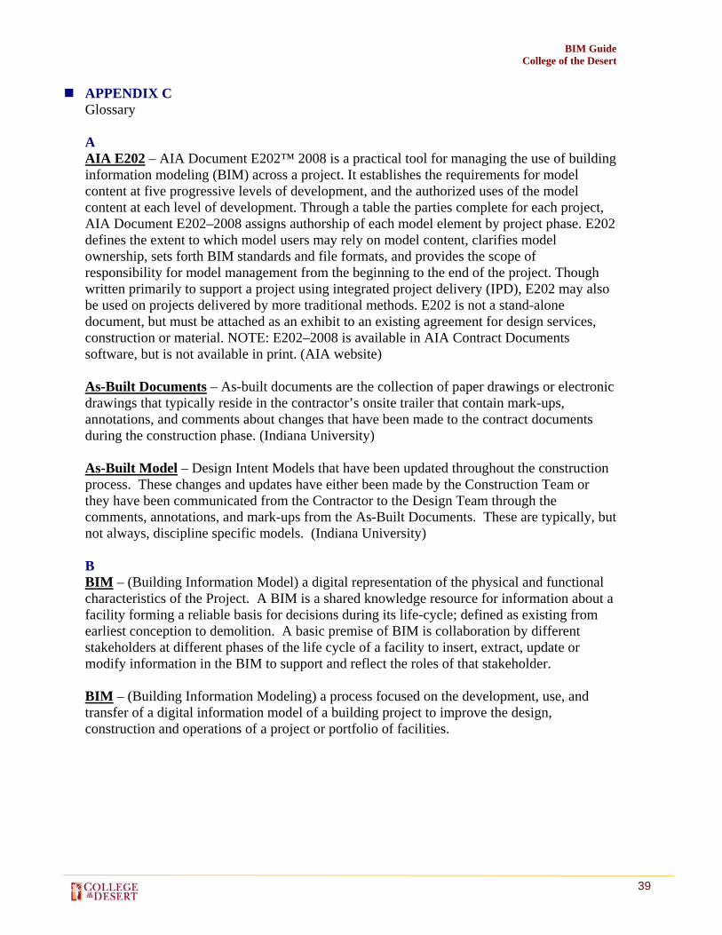
APPENDIX C Glossary A AIA E202 – AIA Document E202™ 2008 is a practical tool for managing the use of building information modeling (BIM) across a project. It establishes the requirements for model content at five progressive levels of development, and the authorized uses of the model content at each level of development. Through a table the parties complete for each project, AIA Document E202–2008 assigns authorship of each model element by project phase. E202 defines the extent to which model users may rely on model content, clarifies model ownership, sets forth BIM standards and file formats, and provides the scope of responsibility for model management from the beginning to the end of the project. Though written primarily to support a project using integrated project delivery (IPD), E202 may also be used on projects delivered by more traditional methods. E202 is not a stand-alone document, but must be attached as an exhibit to an existing agreement for design services, construction or material. NOTE: E202–2008 is available in AIA Contract Documents software, but is not available in print. (AIA website) As-Built Documents – As-built documents are the collection of paper drawings or electronic drawings that typically reside in the contractor’s onsite trailer that contain mark-ups, annotations, and comments about changes that have been made to the contract documents during the construction phase. (Indiana University) As-Built Model – Design Intent Models that have been updated throughout the construction process. These changes and updates have either been made by the Construction Team or they have been communicated from the Contractor to the Design Team through the comments, annotations, and mark-ups from the As-Built Documents. These are typically, but not always, discipline specific models. (Indiana University) B BIM – (Building Information Model) a digital representation of the physical and functional characteristics of the Project. A BIM is a shared knowledge resource for information about a facility forming a reliable basis for decisions during its life-cycle; defined as existing from earliest conception to demolition. A basic premise of BIM is collaboration by different stakeholders at different phases of the life cycle of a facility to insert, extract, update or modify information in the BIM to support and reflect the roles of that stakeholder. BIM – (Building Information Modeling) a process focused on the development, use, and transfer of a digital information model of a building project to improve the design, construction and operations of a project or portfolio of facilities.

BIM Guide College of the Desert
40
BIM Goals – Objectives used to define the potential value of BIM for a project and for project team members. BIM Goals help to define how and why BIM will by used on a project or in an organization. (Pennsylvania State University) BIM Process – A generic name for the practice of performing Building Information Modeling. This process can be planned or unplanned. The BIM Process may also be referred to as the BIM Exectution Process or the BIM Project Execution Process. (Pennsylvania State University) BIM Process Maps – A diagram of how BIM will be applied on a project. (Pennsylvania State University) BIM Project Execution Plan – This document lays out how BIM will be implemented on the project as a result of the decision of the group. (Pennsylvania State University) BIM Tool – A software application used to generate and manipulate building information models. The term can be further qualified to denote specific application areas. For example, “BIM Design Tool” is often used to refer to tools used primarily for architectural design, such as Revit Building, Bentley Architecture, Digital Project, and ArchiCAD. Building Management System (BMS) - is a computer-based control system installed in buildings that controls and monitors the building’s mechanical and electrical equipment such as ventilation, lighting, power systems, fire systems, and security systems. BuildingSMART Alliance – Created to spearhead technical, political, and financial support for advanced digital technology in the real property industry—from concept, design and construction through operations and management—the buildingSMART alliance operates within the independent nonprofit National Institute of Building Sciences (NIBS). (BuildingSMART Alliance website) C CAD – Computer Aided Design. A geometric/symbol based computer drawing system used in art, architecture, engineering, and manufacturing to assist in precision drawing. COBIE – The model and facility data for the commission, operations, and maintenance of the project shall satisfy the Construction Operations Building Information Exchange (COBIE) requirements, and be submitted in compliance with the commissioning requirements. Clash Detection - is a process of discovering the building system conflicts and issues by collaborating in 3D during the coordination process. Sometimes referred to as interference checking and/or interference avoidance. CM at Risk - is a delivery method which entails a commitment by the construction manager to deliver the project within a Guaranteed Maximum Price (GMP), in most cases.

BIM Guide College of the Desert
41
D Design Build – In design-build project delivery, the owner enters into a contract with a design-builder who is obligated to design and construct the project. The design-builder then enters into contracts with architects and construction contractors, as needed. Design Bid Build – When the owner's project is divided into separate contracts for design (with the architect) and construction (with one or more contractors) Design Intent Model – is a BIM model developed by an architect from which the automated construction documents are derived, along with automated schedules, details, and client presentations. E Energy Analysis/Simulation – Energy simulation software tools for evaluation of energy efficiency, renewable energy, and sustainability in buildings. F File Sharing Protocol – Establishing a single shared project server (FTP site) for the upload and exchange of digital models, and the collection of project deliverables at pre-determined milestones. The same shared server shall continue to be used for the same purposes during Construction. Models on this shared server will be fully accessible web based to all team members via assigned site user names and passwords. I IPD – (Integrated Project Delivery) leverages early contributions of knowledge and expertise through the utilization of new technologies, allowing all team members to better realize their highest potentials while expanding the value they provide throughout the project lifecycle. (AIA) IFC – Industry Foundation Class. IFCs are data elements that represent the parts of buildings, or elements of the process, and contain the relevant information about those parts. IFCs are used by computer applications to assemble a computer-readable model of the facility that contains all the information of the parts and their relationships to be shared among project participants. The project model constitutes an object-oriented database of the information shared among project participants and continues to grow as the project goes through design, construction, and operation. The International Alliance for Interoperability (IAI) has created this IFC data exchange format. (LACCD) Information Exchange (IE) – The information passed from one party to another in the BIM process. The parties involved should agree upon and understand what information will be exchanged. These are often in the form of deliverables from a process that will be required as a resource for future processes. (Pennsylvania State University) Interoperability – Refers to the exchange of information among project participants throughout the lifecycle of a facility by direct communication between software applications.

BIM Guide College of the Desert
42
L Level of Development (LOD) – Also called Level of Detail, describes the level of completeness to which a Model Element is developed. M Model Element – A Model Element is a portion of the Building Information Model representing a component, system or assembly within a building or building site. Model Element Author (MEA) – The Model Element Author is the party responsible for developing the content of a specific Model Element to the LOD required for a particular phase of the project. Model User – The Model User refers to any individual or entity authorized to use the Model on the Project, such as for analysis, estimating, or scheduling. O OmniClass – is a classification system for the construction industry. OmniClass is useful for many applications, from organizing library materials, product literature, and project information, to providing a classification structure for electronic databases. It incorporates other extant systems currently in use as the basis of many of its Tables – MasterFormat™ for work results, UniFormat for elements, and EPIC (Electronic Product Information Cooperation) for structuring products. (http://www.omniclass.org/) P Parameter – Any set of physical properties whose values determine the characteristics or behavior of something (Merriam-Webster Online Dictionary) S Stakeholder - Stakeholders are the specific people or groups who have a stake, or an interest, in the outcome of the project. Normally stakeholders are from within the company, and could include internal clients, management, employees, administrators... etc (Visitask.com) U UniFormat – UniFormat, a publication of CSI and CSC, is a method of arranging construction information based on functional elements, or parts of a facility characterized by their functions, without regard to the materials and methods used to accomplish them. These elements are often referred to as systems or assemblies. (http://www.csinet.org/uniformat)
BIM Guide College of the Desert
43
APPENDIX D Index AIA E202 ............................................................................... 9, 10, 11, Appendix B AIA Model Element Table ................................................................. 9, Appendix B As Built Model .................................................................................................13, 17 BIM Lead .....................................................................................................5, 12, 21 Building Management System (BMS) ...................................................................20 Clash Detection ................................................................................................18, 19 COBIE....................................................................................................................13 Design Intent Model ..............................................................................................17 IFC (Industry Foundation Class) .....................................................................17, 20 IPD (Integrated Project Delivery) ............................................................................8 LOD (Level of Development) ..........................................................9, 10, 11, 21, 22 Multiple Prime Contracts .................................................................................5, 7, 8 Origin .....................................................................................................................21 Project Execution Plan .........................................................................12, 13, 15, 17

BIM Guide College of the Desert
44
APPENDIX E Credits
Compiled by RBB Inc., 10980 Wilshire Blvd. Los Angeles CA 90024-3905 Kevin S. Boots, AIA, LEED AP BD+C Sr. Vice President
Richard Andrews Director of Support Services Melissa Keiser, LEED AP BIM Implementation Lead
1. AIA Document E202. (2008). The American Institute of Architects. Retreived September 2010, from http://www.pat.ca/files/pdfs/AIA_091708_E202-2008_eSample_Blank.pdf .
2. Autodesk Inc. BIM Communication Specification. (2008)
3. Indiana University Architect’s Office. Indiana University BIM Guidelines and Standards for Architects, Engineers, and Contractors. September 2009.
4. Build LACCD. LACCD Building Information Modeling Standards (LACCD
BIMS) Version 3.0, March 2010.
5. The Computer Integrated Construction Research Group, The Pennsylvania State University. Building Information Execution Planning Guide. 2010.
6. U.S. Department of Veterans Affairs, Office of Construction & Facilities
Management, VA BIM Guide, April 2010.