Embed Size (px)
Citation preview
ETH Library
Smart Dynamic CastingSlipforming with Flexible Formwork - InlineMeasurement and Control
Conference Paper
Author(s):Lloret Fritschi, Ena; Reiter, Lex; Wangler, Timothy; Gramazio, Fabio; Kohler, Matthias; Flatt, Robert J.
Publication date:2017
Permanent link:https://doi.org/10.3929/ethz-b-000219663
Rights / license:In Copyright - Non-Commercial Use Permitted
This page was generated automatically upon download from the ETH Zurich Research Collection.For more information, please consult the Terms of use.
Paper no. 27
SMART DYNAMIC CASTING SLIPFORMING WITH FLEXIBLE FORMWORK - INLINE MEASUREMENT AND
CONTROL
Ena Lloret Fritschia, Lex Reiterb, Timothy Wanglerb, Fabio Gramazioa, Matthias Kohlera,
Robert J Flattb* a Institute of Technology in Architecture, Department of Architecture, ETH Zurich
b Institute of Building Materials, Civil Engineering Department, ETH Zurich
* Corresponding author
ABSTRACT
Smart Dynamic Casting (SDC) – a robotic prefabrication method for non-standard structures – has
emerged from shaping concrete with a rigid formwork into an almost fully automated system enabling
the production of concrete structures with variable cross-section and geometries using flexible
actuated formworks. The flexible formwork systems have yielded full scale prototypes (up to 3 meters
in height) that vary in shape, volume, thickness and geometry (or a combination of these), and show
that the SDC design space can be significantly expanded, far beyond what has been achieved in
previous studies.
Two different shaping methods were applied. The first method shapes the material locally, at the exit
of the formwork, only allowing a minimal gradient of deformation. The second method shapes the
material globally, across the whole height of formwork, allowing for significant variation in cross
section.
Regardless of whether the deformation occurs locally or globally, any deformation modifies the load
on the concrete at the exit of the formwork, thus requiring continuous inline measurements and
automated feedback loops. A recent successful approach combines formwork pressure and friction
measurements to define the lower and upper strength limits of the shaping window, thereby enabling
more robust control of the process.
This paper presents the current SDC process, with a particular emphasis on how the experimental
setup has changed from previous studies. This includes descriptions of new flexible formwork
typologies, followed by a description of the novel inline measurement technique. Together, these
advances bring the SDC system another step closer to the main objective of the research, which is to
develop a fully automated system that enables efficient production of load bearing structures in a
continuous digital chain.
Keywords: Architecture, non-standard, flexible formwork, inline control system, automated
continuous production system, concrete, digital fabrication
1. INTRODUCTION
Advances in digital fabrication over the past ten years have promised to revolutionise the field of
architecture by enabling design of complex and optimized structures. The application of digital
fabrication to concrete technology has been of particular interest to researchers, as the material’s
versatility lends itself well to freeform design [1]. Over the past few years, a number of studies have
used digital fabrication methods in the design and implementation of freeform concrete structures.
However, these have been focused primarily on using CNC milled formwork [2], which has the
downside of being a wasteful process as the custom formwork is used only once. Another new method
is to 3D print via layered extrusion processes, such as Contour Crafting [3]. However, this method
requires the addition of reinforcement after the structure is printed, a limiting factor in particular for
double curved shapes. More recently, the Mesh Mould process [4] has been used to 3D print a
functional stay-in-place formwork, with single as well as double curvature, by robotically fabricating a
steel wire mesh that would act both as a formwork as well as the structural reinforcement. While this
method is still in development, it nonetheless promises to become an efficient technique for the
construction of nonstandard, freeform concrete structures.
Smart Dynamic Casting (SDC), presented here, is an alternative digital fabrication process for
prefabricating custom elements [5-6]. The process takes its inspiration from slipforming, a well-known
concrete technology for on-site construction of structural elements such as cores and pillars. In SDC,
fresh concrete is poured into the top of a formwork that is much smaller than the final element, and
comes out the bottom in a partially hardened state – with enough strength to support its own weight
and the weight of what is in the formwork, but still soft enough that it can be shaped. This process
requires control of the hydration kinetics, as flocculation alone is insufficient for the structure to
support its own weight once it grows beyond half meter in height [1]. In SDC, hydration is controlled
via a novel set-on-demand system, where a batch of massively retarded concrete is incrementally
activated with accelerators before being placed in the formwork [7-9]. The background and
development of this process are described in the following section.
2. OVERALL SDC SETUP
In the early stage of development, the SDC process was guided by a feedback system consisting of a
digital controlled penetrometer measuring the strength evolution of the material, remote from the
formwork [5-6, 8]. Batches of concrete in this early stage were sequentially accelerated and manually
placed in a pump which fed the material into the formwork. Now, however, SDC is managed by a
digitally controlled feeding system that automatically accelerates and places the material into the
formwork. The remote feedback system is now used simply to indicate when to initiate slipping. To
gain information regarding the strength evolution of the material in the formwork, our new feedback
system measures the material directly in the formwork, a necessary step towards fully automating the
process and assuring robustness when dynamically changing the formwork cross section.
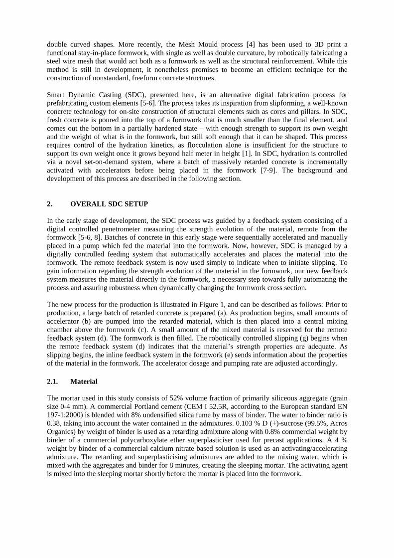
The new process for the production is illustrated in Figure 1, and can be described as follows: Prior to
production, a large batch of retarded concrete is prepared (a). As production begins, small amounts of
accelerator (b) are pumped into the retarded material, which is then placed into a central mixing
chamber above the formwork (c). A small amount of the mixed material is reserved for the remote
feedback system (d). The formwork is then filled. The robotically controlled slipping (g) begins when
the remote feedback system (d) indicates that the material’s strength properties are adequate. As
slipping begins, the inline feedback system in the formwork (e) sends information about the properties
of the material in the formwork. The accelerator dosage and pumping rate are adjusted accordingly.
2.1. Material
The mortar used in this study consists of 52% volume fraction of primarily siliceous aggregate (grain
size 0-4 mm). A commercial Portland cement (CEM I 52.5R, according to the European standard EN
197-1:2000) is blended with 8% undensified silica fume by mass of binder. The water to binder ratio is
0.38, taking into account the water contained in the admixtures. 0.103 % D (+)-sucrose (99.5%, Acros
Organics) by weight of binder is used as a retarding admixture along with 0.8% commercial weight by
binder of a commercial polycarboxylate ether superplasticiser used for precast applications. A 4 %
weight by binder of a commercial calcium nitrate based solution is used as an activating/accelerating
admixture. The retarding and superplasticising admixtures are added to the mixing water, which is
mixed with the aggregates and binder for 8 minutes, creating the sleeping mortar. The activating agent
is mixed into the sleeping mortar shortly before the mortar is placed into the formwork.
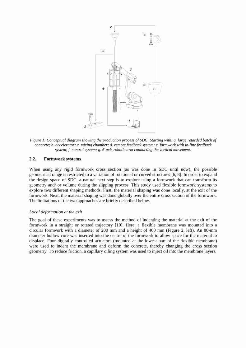
Figure 1: Conceptual diagram showing the production process of SDC. Starting with: a. large retarded batch of
concrete; b. accelerator; c. mixing chamber; d. remote feedback system; e. formwork with in-line feedback
system; f. control system; g. 6-axis robotic arm conducting the vertical movement.
2.2. Formwork systems
When using any rigid formwork cross section (as was done in SDC until now), the possible
geometrical range is restricted to a variation of rotational or curved structures [6, 8]. In order to expand
the design space of SDC, a natural next step is to explore using a formwork that can transform its
geometry and/ or volume during the slipping process. This study used flexible formwork systems to
explore two different shaping methods. First, the material shaping was done locally, at the exit of the
formwork. Next, the material shaping was done globally over the entire cross section of the formwork.
The limitations of the two approaches are briefly described below.
Local deformation at the exit
The goal of these experiments was to assess the method of indenting the material at the exit of the
formwork in a straight or rotated trajectory [10]. Here, a flexible membrane was mounted into a
circular formwork with a diameter of 200 mm and a height of 400 mm (Figure 2, left). An 80-mm
diameter hollow core was inserted into the centre of the formwork to allow space for the material to
displace. Four digitally controlled actuators (mounted at the lowest part of the flexible membrane)
were used to indent the membrane and deform the concrete, thereby changing the cross section
geometry. To reduce friction, a capillary oiling system was used to inject oil into the membrane layers.
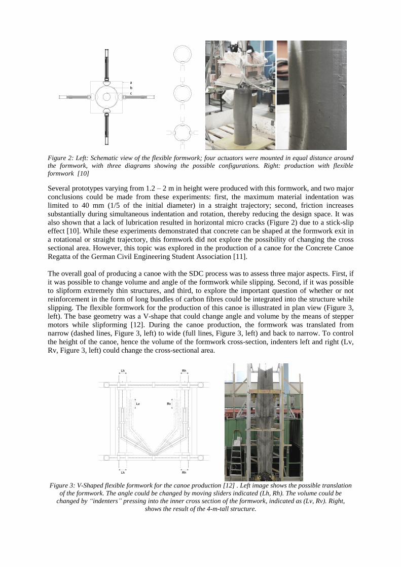
Figure 2: Left: Schematic view of the flexible formwork; four actuators were mounted in equal distance around
the formwork, with three diagrams showing the possible configurations. Right: production with flexible
formwork [10]
Several prototypes varying from 1.2 – 2 m in height were produced with this formwork, and two major
conclusions could be made from these experiments: first, the maximum material indentation was
limited to 40 mm (1/5 of the initial diameter) in a straight trajectory; second, friction increases
substantially during simultaneous indentation and rotation, thereby reducing the design space. It was
also shown that a lack of lubrication resulted in horizontal micro cracks (Figure 2) due to a stick-slip
effect [10]. While these experiments demonstrated that concrete can be shaped at the formwork exit in
a rotational or straight trajectory, this formwork did not explore the possibility of changing the cross
sectional area. However, this topic was explored in the production of a canoe for the Concrete Canoe
Regatta of the German Civil Engineering Student Association [11].
The overall goal of producing a canoe with the SDC process was to assess three major aspects. First, if
it was possible to change volume and angle of the formwork while slipping. Second, if it was possible
to slipform extremely thin structures, and third, to explore the important question of whether or not
reinforcement in the form of long bundles of carbon fibres could be integrated into the structure while
slipping. The flexible formwork for the production of this canoe is illustrated in plan view (Figure 3,
left). The base geometry was a V-shape that could change angle and volume by the means of stepper
motors while slipforming [12]. During the canoe production, the formwork was translated from
narrow (dashed lines, Figure 3, left) to wide (full lines, Figure 3, left) and back to narrow. To control
the height of the canoe, hence the volume of the formwork cross-section, indenters left and right (Lv,
Rv, Figure 3, left) could change the cross-sectional area.
Figure 3: V-Shaped flexible formwork for the canoe production [12] . Left image shows the possible translation
of the formwork. The angle could be changed by moving sliders indicated (Lh, Rh). The volume could be
changed by “indenters” pressing into the inner cross section of the formwork, indicated as (Lv, Rv). Right,
shows the result of the 4-m-tall structure.
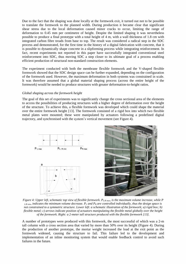
Due to the fact that the shaping was done locally at the formwork exit, it turned out not to be possible
to translate the formwork to the planned width. During production it became clear that significant
shear stress due to the local deformation caused minor cracks to occur, limiting the range of
deformation to 0.45 mm per centimetre of height. Despite the limited shaping it was nevertheless
possible to produce a final prototype with a total height of 4 m, with a wall thickness of 1.8 cm with
integrated carbon fibre treads from base to top. The result was considered a radical step in the SDC
process and demonstrated, for the first time in the history of a digital fabrication with concrete, that it
is possible to dynamically shape concrete in a slipforming process while integrating reinforcement. In
fact, recent experiments not reported in this paper have successfully integrated conventional steel
reinforcement into SDC, thus moving SDC a step closer to its ultimate goal of a process enabling
efficient production of structural non-standard construction elements.
The experiment conducted with both the membrane flexible formwork and the V-shaped flexible
formwork showed that the SDC design space can be further expanded, depending on the configuration
of the formwork used. However, the maximum deformation in both systems was constrained in scale.
It was therefore assumed that a global material shaping process (across the entire height of the
formwork) would be needed to produce structures with greater deformation-to-height ratios.
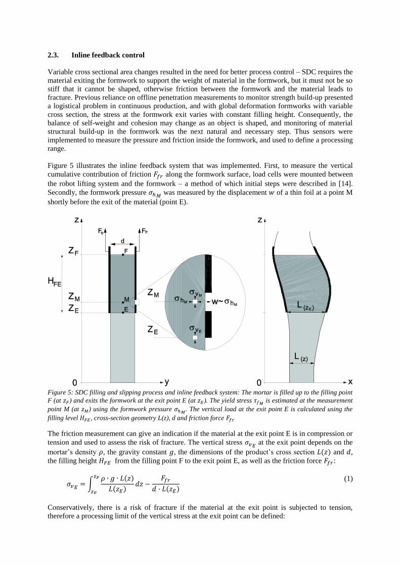
Global shaping across the formwork height
The goal of this set of experiments was to significantly change the cross sectional area of the elements
to access the possibilities of producing structures with a higher degree of deformation over the height
of the structure. To achieve this, a flexible formwork was developed which could shape the material
over the entire formwork height [13]. The formwork consisted of a rigid box into which two flexible
metal plates were mounted; these were manipulated by actuators following a predefined digital
trajectory, and synchronised with the system’s vertical movement (see Figure 4).
Figure 4: Upper left, schematic top view of flexible formwork. PL/R max, is the maximum volume increase, while P
L/R min, indicates the minimum volume decrease. PL and PR are controlled individually, thus the design space is
not constrained to a symmetric structure. Lower left: a schematic illustration of the formwork; a) rigid box; b)
flexible metal; c) arrows indicate position of actuators manipulating the flexible metal globally over the height
of the formwork. Right: a 2-meter tall structure produced with the flexible formwork [13].
A number of prototypes were produced with this formwork, the most successful of which was a 2-m
tall column with a cross section area that varied by more than 50% over its height (Figure 4). During
the production of another prototype, the mortar weight increased the load at the exit point as the
formwork widened, causing the structure to fail. This failure led to the development and
implementation of an inline monitoring system that would enable feedback control to avoid such
failures in the future.
2.3. Inline feedback control
Variable cross sectional area changes resulted in the need for better process control – SDC requires the
material exiting the formwork to support the weight of material in the formwork, but it must not be so
stiff that it cannot be shaped, otherwise friction between the formwork and the material leads to
fracture. Previous reliance on offline penetration measurements to monitor strength build-up presented
a logistical problem in continuous production, and with global deformation formworks with variable
cross section, the stress at the formwork exit varies with constant filling height. Consequently, the
balance of self-weight and cohesion may change as an object is shaped, and monitoring of material
structural build-up in the formwork was the next natural and necessary step. Thus sensors were
implemented to measure the pressure and friction inside the formwork, and used to define a processing
range.
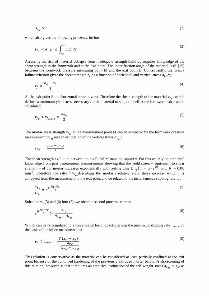
Figure 5 illustrates the inline feedback system that was implemented. First, to measure the vertical
cumulative contribution of friction 𝐹𝑓𝑟 along the formwork surface, load cells were mounted between
the robot lifting system and the formwork – a method of which initial steps were described in [14].
Secondly, the formwork pressure 𝜎ℎ𝑀 was measured by the displacement 𝑤 of a thin foil at a point M
shortly before the exit of the material (point E).
Figure 5: SDC filling and slipping process and inline feedback system: The mortar is filled up to the filling point
F (at 𝑧𝐹) and exits the formwork at the exit point E (at 𝑧𝐸). The yield stress 𝜏𝑓𝑀 is estimated at the measurement
point M (at 𝑧𝑀) using the formwork pressure 𝜎ℎ𝑀. The vertical load at the exit point E is calculated using the
filling level 𝐻𝐹𝐸 , cross-section geometry L(z), d and friction force 𝐹𝑓𝑟
The friction measurement can give an indication if the material at the exit point E is in compression or
tension and used to assess the risk of fracture. The vertical stress 𝜎𝑣𝐸 at the exit point depends on the
mortar’s density 𝜌, the gravity constant 𝑔, the dimensions of the product’s cross section 𝐿(𝑧) and 𝑑,
the filling height 𝐻𝐹𝐸 from the filling point F to the exit point E, as well as the friction force 𝐹𝑓𝑟:
𝜎𝑣𝐸= ∫
𝜌 ∙ 𝑔 ∙ 𝐿(𝑧)
𝐿(𝑧𝐸)
𝑧𝐹
𝑧𝐸
𝑑𝑧 −𝐹𝑓𝑟
𝑑 · 𝐿(𝑧𝐸)
(1)
Conservatively, there is a risk of fracture if the material at the exit point is subjected to tension,
therefore a processing limit of the vertical stress at the exit point can be defined:
𝜎𝑣𝐸> 0 (2)
which also gives the following process criterion
𝐹𝑓𝑟 < 𝑑 · 𝜌 ∙ 𝑔 ∫ 𝐿(𝑧)𝑑𝑧𝑧𝐹
𝑧𝐸
(3)
Assessing the risk of material collapse from inadequate strength build-up requires knowledge of the
shear strength in the formwork and at the exit point. The inner friction angle of the material is 0° [15]
between the formwork pressure measuring point M and the exit point E. Consequently, the Tresca
failure criterion gives the shear strength 𝜏𝑓 as a function of horizontal and vertical stress 𝜎ℎ, 𝜎𝑣:
𝜏𝑓 = 𝜎𝑣 − 𝜎ℎ
2 (4)
At the exit point E, the horizontal stress is zero. Therefore the shear strength of the material 𝜏𝑓𝐸, which
defines a minimum yield stress necessary for the material to support itself at the formwork exit, can be
calculated:
𝜏𝑓𝐸> 𝜏𝑓𝐸,𝑚𝑖𝑛
= 𝜎𝑣𝐸
2
(5)
The mortar shear strength 𝜏𝑓𝑀 at the measurement point M can be estimated by the formwork pressure
measurement 𝜎ℎ𝑀 and an estimation of the vertical stress 𝜎𝑣𝑀
:
𝜏𝑓𝑀 = 𝜎𝑣𝑀 − 𝜎ℎ𝑀
2 (6)
The shear strength evolution between points E and M must be captured. For this we rely on empirical
knowledge from past penetrometer measurements showing that the yield stress – equivalent to shear
strength – of our mortar increases exponentially with resting time t: 𝜏𝑓(𝑡) = 𝛼 ∙ 𝑒𝛽𝑡, with 𝛽 ≈ 0.08
min-1. Therefore the ratio 𝜏𝑓𝐸
𝜏𝑓𝑀⁄ describing the mortar’s relative yield stress increase while it is
conveyed from the measurement to the exit point and be related to the instantaneous slipping rate 𝑣𝑠:
𝜏𝑓𝐸
𝜏𝑓𝑀
= 𝑒𝛽
𝑧𝑀−𝑧𝐸𝑣𝑠
(7)
Substituting (5) and (6) into (7), we obtain a second process criterion:
𝑒𝛽
𝑧𝑀−𝑧𝐸𝑣𝑠 >
𝜎𝑣𝐸
𝜎𝑣𝑀− 𝜎ℎ𝑀
(8)
Which can be reformulated to a more useful form, directly giving the maximum slipping rate 𝑣𝑚𝑎𝑥 on
the basis of the inline measurements:
𝑣𝑠 < 𝑣𝑚𝑎𝑥 = 𝛽 (𝑧𝑀 − 𝑧𝐸)
ln𝜎𝑣𝐸
𝜎𝑣𝑀− 𝜎ℎ𝑀
(9)
This relation is conservative as the material can be considered at least partially confined at the exit
point because of the continued hardening of the previously extruded mortar below. A shortcoming of
this relation, however, is that it requires an empirical estimation of the self-weight stress 𝜎𝑣𝑀 at 𝑧𝑀 as
the distribution of friction in the formwork is unknown. So far, we assume that friction stress is
proportional to the mortar depth.
The processing criteria in (2) and (9) were tested directly in three experiments. In all experiments,
samples with a fixed cross section L(z)=d=15 cm were produced. The formwork pressure measurement
was positioned 43 mm above the exit point of the formwork. Slipping was initiated based upon
penetrometer results and different slipping rates were chosen, including typical (Case 1), slower (Case
2) and faster (Case 3) rates, with Cases 2 and 3 intended to cause failures at both process boundaries.
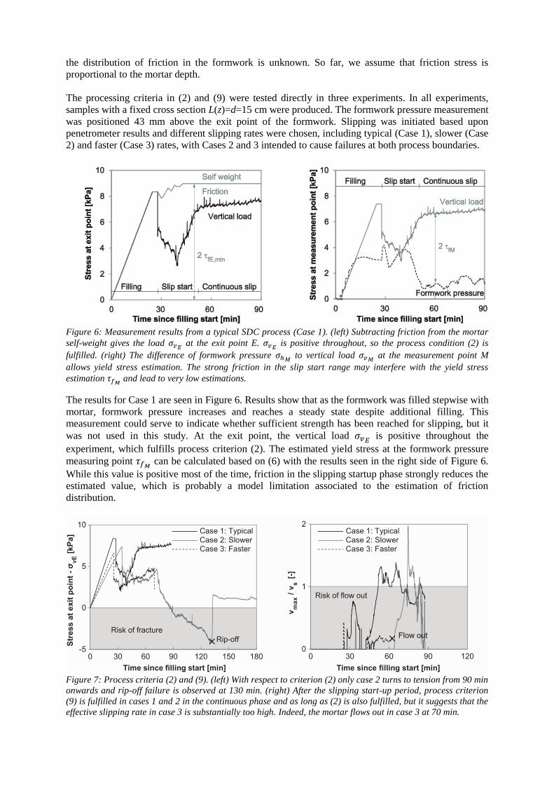
Figure 6: Measurement results from a typical SDC process (Case 1). (left) Subtracting friction from the mortar
self-weight gives the load 𝜎𝑣𝐸 at the exit point E. 𝜎𝑣𝐸
is positive throughout, so the process condition (2) is
fulfilled. (right) The difference of formwork pressure 𝜎ℎ𝑀 to vertical load 𝜎𝑣𝑀
at the measurement point M
allows yield stress estimation. The strong friction in the slip start range may interfere with the yield stress
estimation 𝜏𝑓𝑀 and lead to very low estimations.
The results for Case 1 are seen in Figure 6. Results show that as the formwork was filled stepwise with
mortar, formwork pressure increases and reaches a steady state despite additional filling. This
measurement could serve to indicate whether sufficient strength has been reached for slipping, but it
was not used in this study. At the exit point, the vertical load 𝜎𝑣𝐸 is positive throughout the
experiment, which fulfills process criterion (2). The estimated yield stress at the formwork pressure
measuring point 𝜏𝑓𝑀 can be calculated based on (6) with the results seen in the right side of Figure 6.
While this value is positive most of the time, friction in the slipping startup phase strongly reduces the
estimated value, which is probably a model limitation associated to the estimation of friction
distribution.
Figure 7: Process criteria (2) and (9). (left) With respect to criterion (2) only case 2 turns to tension from 90 min
onwards and rip-off failure is observed at 130 min. (right) After the slipping start-up period, process criterion
(9) is fulfilled in cases 1 and 2 in the continuous phase and as long as (2) is also fulfilled, but it suggests that the
effective slipping rate in case 3 is substantially too high. Indeed, the mortar flows out in case 3 at 70 min.
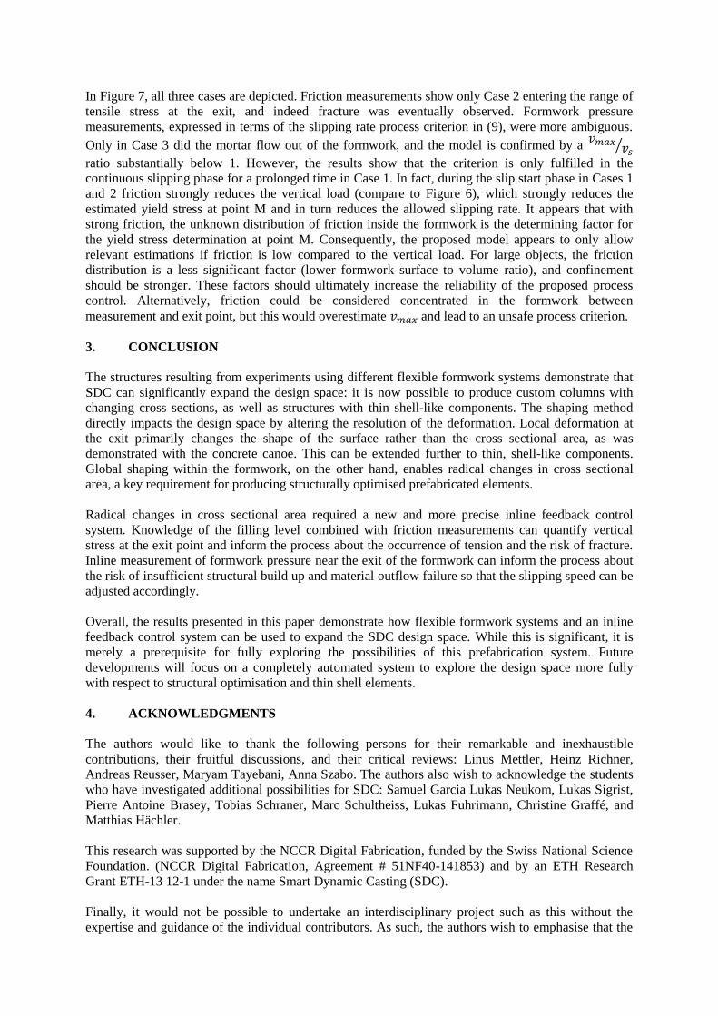
In Figure 7, all three cases are depicted. Friction measurements show only Case 2 entering the range of
tensile stress at the exit, and indeed fracture was eventually observed. Formwork pressure
measurements, expressed in terms of the slipping rate process criterion in (9), were more ambiguous.
Only in Case 3 did the mortar flow out of the formwork, and the model is confirmed by a 𝑣𝑚𝑎𝑥
𝑣𝑠⁄
ratio substantially below 1. However, the results show that the criterion is only fulfilled in the
continuous slipping phase for a prolonged time in Case 1. In fact, during the slip start phase in Cases 1
and 2 friction strongly reduces the vertical load (compare to Figure 6), which strongly reduces the
estimated yield stress at point M and in turn reduces the allowed slipping rate. It appears that with
strong friction, the unknown distribution of friction inside the formwork is the determining factor for
the yield stress determination at point M. Consequently, the proposed model appears to only allow
relevant estimations if friction is low compared to the vertical load. For large objects, the friction
distribution is a less significant factor (lower formwork surface to volume ratio), and confinement
should be stronger. These factors should ultimately increase the reliability of the proposed process
control. Alternatively, friction could be considered concentrated in the formwork between
measurement and exit point, but this would overestimate 𝑣𝑚𝑎𝑥 and lead to an unsafe process criterion.
3. CONCLUSION
The structures resulting from experiments using different flexible formwork systems demonstrate that
SDC can significantly expand the design space: it is now possible to produce custom columns with
changing cross sections, as well as structures with thin shell-like components. The shaping method
directly impacts the design space by altering the resolution of the deformation. Local deformation at
the exit primarily changes the shape of the surface rather than the cross sectional area, as was
demonstrated with the concrete canoe. This can be extended further to thin, shell-like components.
Global shaping within the formwork, on the other hand, enables radical changes in cross sectional
area, a key requirement for producing structurally optimised prefabricated elements.
Radical changes in cross sectional area required a new and more precise inline feedback control
system. Knowledge of the filling level combined with friction measurements can quantify vertical
stress at the exit point and inform the process about the occurrence of tension and the risk of fracture.
Inline measurement of formwork pressure near the exit of the formwork can inform the process about
the risk of insufficient structural build up and material outflow failure so that the slipping speed can be
adjusted accordingly.
Overall, the results presented in this paper demonstrate how flexible formwork systems and an inline
feedback control system can be used to expand the SDC design space. While this is significant, it is
merely a prerequisite for fully exploring the possibilities of this prefabrication system. Future
developments will focus on a completely automated system to explore the design space more fully
with respect to structural optimisation and thin shell elements.
4. ACKNOWLEDGMENTS
The authors would like to thank the following persons for their remarkable and inexhaustible
contributions, their fruitful discussions, and their critical reviews: Linus Mettler, Heinz Richner,
Andreas Reusser, Maryam Tayebani, Anna Szabo. The authors also wish to acknowledge the students
who have investigated additional possibilities for SDC: Samuel Garcia Lukas Neukom, Lukas Sigrist,
Pierre Antoine Brasey, Tobias Schraner, Marc Schultheiss, Lukas Fuhrimann, Christine Graffé, and
Matthias Hächler.
This research was supported by the NCCR Digital Fabrication, funded by the Swiss National Science
Foundation. (NCCR Digital Fabrication, Agreement # 51NF40-141853) and by an ETH Research
Grant ETH-13 12-1 under the name Smart Dynamic Casting (SDC).
Finally, it would not be possible to undertake an interdisciplinary project such as this without the
expertise and guidance of the individual contributors. As such, the authors wish to emphasise that the
first two listed authors – Ena Lloret-Fritschi and Lex Reiter – must also be acknowledged as main
contributors to this paper.
5. REFERENCES
1. Wangler, T., Lloret, E., Reiter, L., Hack, N., Gramazio, F., Kohler, M., Bernhard, M., Dillenburger,
B., Buchli, J., Roussel, N., and R. Flatt. “Digital Concrete: Opportunities and Challenges”.
RILEM Tech. Lett. (2016) 1: 67-75.
2. Li L, Yan J, Xing Z. Energy requirements evaluation of milling machines based on
thermal equilibrium and empirical modelling. J Clean Prod. (2013) 52: 113–21.
3. Khoshnevis B. Automated construction by contour crafting—related robotics and information
technologies. Best ISARC 2002. (2004) 13 (1):5–19.
4. Hack N, Lauer WV. Mesh-Mould: Robotically Fabricated Spatial Meshes as Reinforced Concrete
Formwork. Archit Des. (2014) 84 (3): 44–53.
5. Lloret E, Gramazio F, Kohler M, Langenberg S. Complex Concrete Structures: Merging existing
casting techniques with digital fabrication. CAADRIA Singapore (2013) p. 613–622.
6. Lloret E, Shahab AR, Linus M, Flatt RJ, Gramazio F, Kohler M, et al. Complex concrete
structures: Merging existing casting techniques with digital fabrication. Computer-Aided Des
(2014) 60: 40-49.
7. Shahab AR, Lloret E, Fischer P, Gramazio F, Kohler M, Flatt RJ. Smart dynamic casting or how
to exploit the liquid to solid transition in cementitious materials. In Proc CD 1st Int Conf
Rheol Process Constr Mater 7th Int Conf Self-Compact Concr Paris Fr. (2013).
8. Lloret E, Mettler LK, Shahab AR, Gramazio F, Kohler M, Flatt RJ. Smart Dynamic Casting: A
robotic fabrication system for complex structures. In: Proceedings of 1st Concrete Innovation
Conference, Oslo, Norway (2014).
9. Reiter L, Palacios M, Wangler T, Flatt RJ. Putting concrete to sleep and waking it up with
chemical admixtures. In: Proceedings 11th CanmetACI International Conference Superplast
Chem Admix Concr, ACI, Ottawa. Ottawa, ON, Canada, (2015) p. 145–54.
10. Lloret Fritschi E. Smart Dynamic Casting A digital fabrication method for non-standard concrete
structures [Doctoral thesis] ETH Zürich, Zürich, Switzerland; (2016).
11. Concrete canoe regatta. Available from: https://www.baug.ethz.ch/en/news-and-
events/news/2015/07/concrete-canoe-launch.html accessed 30 Oct. 2016.
12. Fuhrimann L, Graffé C, Hächler M. Betonkanu: Smart Dynamic Casting [Bachelor thesis] ETH
Zürich, Zürich, Switzerland (2015).
13. Schraner T, Sigrist L, Brasey PA. Smart Dynamic Casting: Investigating the Process Constraints
[Bachelor thesis] ETH Zürich, Zürich, Switzerland (2016).
14. Schultheiss M, Wangler TP, Reiter L, Flatt RJ. Feedback control of Smart Dynamic Casting
through formwork friction measurements. In Proc. CD 8th Int RILEM Symp. on Self-
Compacting Concrete, Washington, DC, USA, (2016).
15. Mettler LK, Wittel FK, Flatt RJ, Herrmann HJ. Evolution of strength and failure of SCC during
early hydration. Cem Concr Res. (2016) 89: 288–296.