Embed Size (px)
Citation preview
8/11/2019 38103 - Muhammad Wisnu C - Electromagnetics C
http://slidepdf.com/reader/full/38103-muhammad-wisnu-c-electromagnetics-c 1/7
Elektromagnetika
Kelas C
Muhammad Wisnu Cakrawiguna
11/318537/TK/38103
Ali!ation o" Magneti! #arti!le $nse!tion in the %ield o" the &o!omoti'e
$ndustr(
A)stra!t* The magnetic particle method is established since 80 years as a method for the prove of
surface cracks in ferromagnetic material. The MT method (MT = magnetic testing) is one of the most
simple and most sensitive methods in NT. !sing MT surface defects can be detected safely even alongcomple" geometries. The most important cause of a damage# the crack# the surface of a component is t$o
times $eaker than the inside. This leads us to the fact that the highest forces affect the $eakest regions of a
part. ue to this# surface crack detection once more sho$s its significance in mass production. %ince theMT results are al$ays pictorial the magnetic particle testing method is a integral NT method that
perfectly matches the sensory needs of the human inspector. ue to this and due to the fact that the process
of magneti&ation and spraying can be applied upon the $hole surface of the component in one go# the MT
method sho$s a very high potential to be fully automated and production line integrated. The follo$ing passages $ill sho$ e"amples from the locomotive industry that $ill give an idea ho$ magnetic testing
combined $ith machine vision and a self controlling structure turns into a fully automated and production
integrated NT method.
Ke(words' Nondestructive Testing# Magnetic article *nspection# +ocomotive *ndustry#
Machine ,ision
$ntrodu!tion
Material defects are un$anted
contaminants right from ra$ material tofurnished products due to inade-uate
process adopted during metallurgical
change manufacturing etc. Material
defects can be appeared in differentforms. s an e"ample the some defects
have to be mentioned here non metallicinclusions defects# manufacturers
defects# high surface decarburi&ation
defects# bad microstructure defects#
surface corrosion defects# mechanicaldamage defects# surface defect# *nternal
defects etc.
The represented e"amples don/thave to lead to the failure of the material
in every case. These are merelye"amined on the material surface andmaterial insides as $ell as of structure
anomalies# $hich differs from the
standard. efects play a crucial role in
influencing the various materials properties# and e"hibit comple" structure
on varying length scales from electronic
structure of the defect core (sub
nanometer and belo$) to elastic fields of
the continuum (micrometer and beyond).efects in materials may be
detected by various processes such as
Magnetic particle inspection# ray
radiography# 1amma radiography#!ltrasonic testing# 2lectrical method#
amping test# Nonmagnetic method of nondestructive testing# 3ptical
holography method and 4ardness test.
This study is limited to
surface5subsurface imperfection $hichis detected through magnetic particle
crack detection techni-ue each process is
re-uired visual inspection. %o it is$orking to discuss about visual
imperfection.,isual testing is probably themost important of all magnetic particle
crack detection tests. *t can often provide
valuable information about defects. The
visual inspection ho$ever should not beconfined only to the structure being
investigated. *t should also include
8/11/2019 38103 - Muhammad Wisnu C - Electromagnetics C
http://slidepdf.com/reader/full/38103-muhammad-wisnu-c-electromagnetics-c 2/7
neighboring structures# the surrounding
environment and the climatic and
services condition. This test report helpsthe component authority to allo$ their
safe use in the installation. ue to time
constraints it $as decided to take uponly magnetic particle crack detection
testing of locomotive components. %o
this is an attempt to learn about themagnetic particle crack detection testing
of materials in general# but locomotive
gear components in particular.
1+ Magneti! testing o" dri'e sha"ts
3ne application from the field of
the sub suppliers of automotive parts is
the fully locomotive inspection of driveshafts. 2"ample# rive shafts are
cylindrical parts of a length of 600 mmto 70 mm and a diameter of 9: mm to
6; mm.
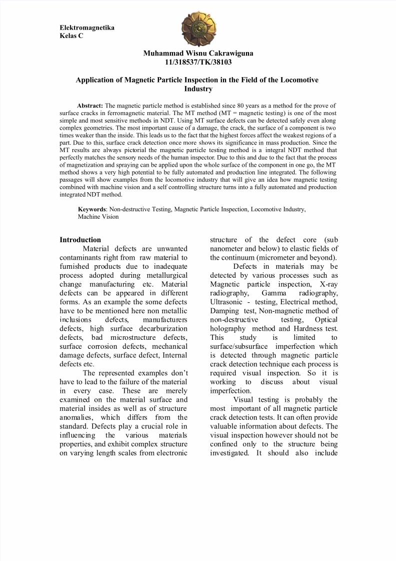
<ig. 9' rive shaft# length' 90 mm<igure 9 sho$s such a shaft that
is toothed and hardened at both ends.
Typical fla$s on this components arematerial a hardening defects. <igure;
sho$s a materials defect after
magneti&ation and spraying $ith M*
test ink under !, light. The system basically is designed as a $alking beam
that leads the parts into the single
stations of the inspection process. <igure6 sho$s the part entrance of the machine
that is designed as a slope on $hich the
parts are piled up in a ro$.
<ig.;' Material defect under !, light
<ig. 6' art entrance of the M* system
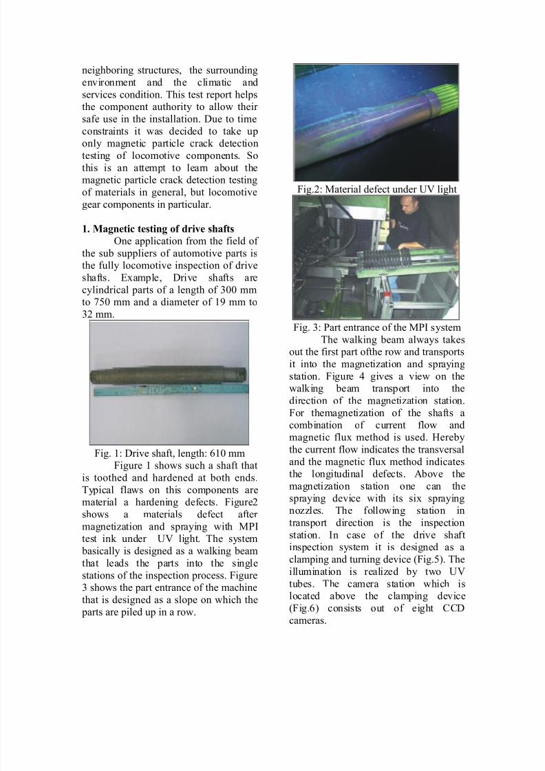
The $alking beam al$ays takesout the first part ofthe ro$ and transports
it into the magneti&ation and spraying
station. <igure > gives a vie$ on the$alking beam transport into the
direction of the magneti&ation station.<or themagneti&ation of the shafts acombination of current flo$ and
magnetic flu" method is used. 4ereby
the current flo$ indicates the transversal
and the magnetic flu" method indicatesthe longitudinal defects. bove the
magneti&ation station one can the
spraying device $ith its si" sprayingno&&les. The follo$ing station in
transport direction is the inspection
station. *n case of the drive shaftinspection system it is designed as a
clamping and turning device (<ig.). The
illumination is reali&ed by t$o !,
tubes. The camera station $hich islocated above the clamping device
(<ig.) consists out of eight ??
cameras.
8/11/2019 38103 - Muhammad Wisnu C - Electromagnetics C
http://slidepdf.com/reader/full/38103-muhammad-wisnu-c-electromagnetics-c 3/7
<ig. >' @alking beam in transport
direction
<ig.' ?lamping and turning device in
inspection station
3ne of the eight cameras ismounted to a linear positioning system.
This enables the machine to adAust itself
to the different shaft length thatare processed in the system.
<ig. ' ?amera station
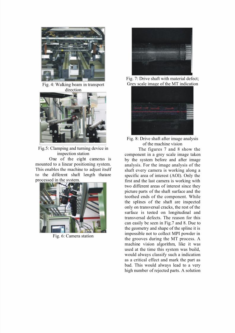
<ig. 7' rive shaft $ith material defectB1rey scale image of the MT indication
<ig. 8' rive shaft after image analysis
of the machine vision
The figures 7 and 8 sho$ thecomponent in a grey scale image taken
by the system before and after image
analysis. <or the image analysis of theshaft every camera is $orking along a
specific area of interest (3*). 3nly thefirst and the last camera is $orking $itht$o different areas of interest since they
picture parts of the shaft surface and the
toothed ends of the component. @hilethe splines of the shaft are inspected
only on transversal cracks# the rest of the
surface is tested on longitudinal and
transversal defects. The reason for thiscan easily be seen in <ig.7 and 8. ue to
the geometry and shape of the spline it is
impossible not to collect M* po$der inthe grooves during the MT process.
machine vision algorithm# like it $as
used at the time this system $as build#$ould al$ays classify such a indication
as a critical effect and mark the part as
bad. This $ould al$ays lead to a very
high number of reAected parts. solution
8/11/2019 38103 - Muhammad Wisnu C - Electromagnetics C
http://slidepdf.com/reader/full/38103-muhammad-wisnu-c-electromagnetics-c 4/7
to prevent false reAection in this case
$ould be a kind of a peeling algorithm
that can distinguish bet$een a real crack and a false indication. %uch an algorithm
peels off the circumference of an obAect
$ith a one pi"el $idth. ue to the factthat a realcrack indication is much more
narro$ than the false indication of a
groove it is easy to see that a real crack $ould vanish after one or t$o goes
$hile the indication of the groove $ould
still remain. *n this $ay the automatic
decision $hether a indication is a crack or a false indication can be made very
easy and safe. The camera set up used in
this machine is fully synchroni&ed to
meet the customers cycle time needs.ppending to the inspection station the
$ork piece gets demagneti&ed. This process is carried out in a yoke the is
build in the same $ay as the yoke in the
magneti&ing station. fter demagneti&ation the components are
handed over to a$ashing machine.
<igure : sho$s the technical data of the
drive shaft testing system.
<ig.:' Technical data of the MT shaftsystem
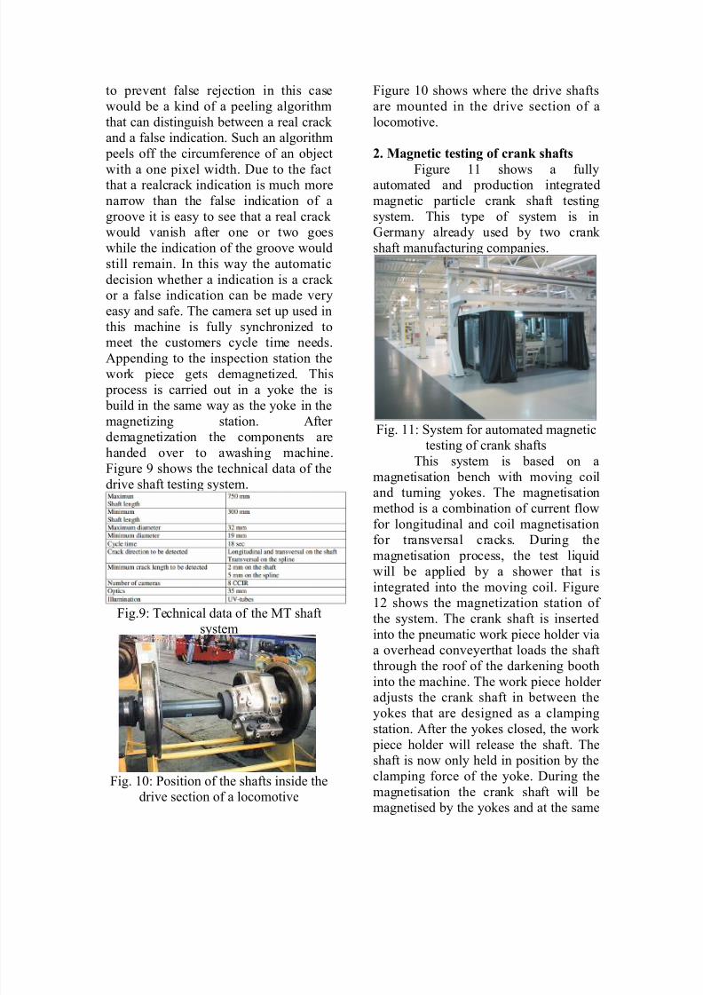
<ig. 90' osition of the shafts inside thedrive section of a locomotive
<igure 90 sho$s $here the drive shafts
are mounted in the drive section of a
locomotive.
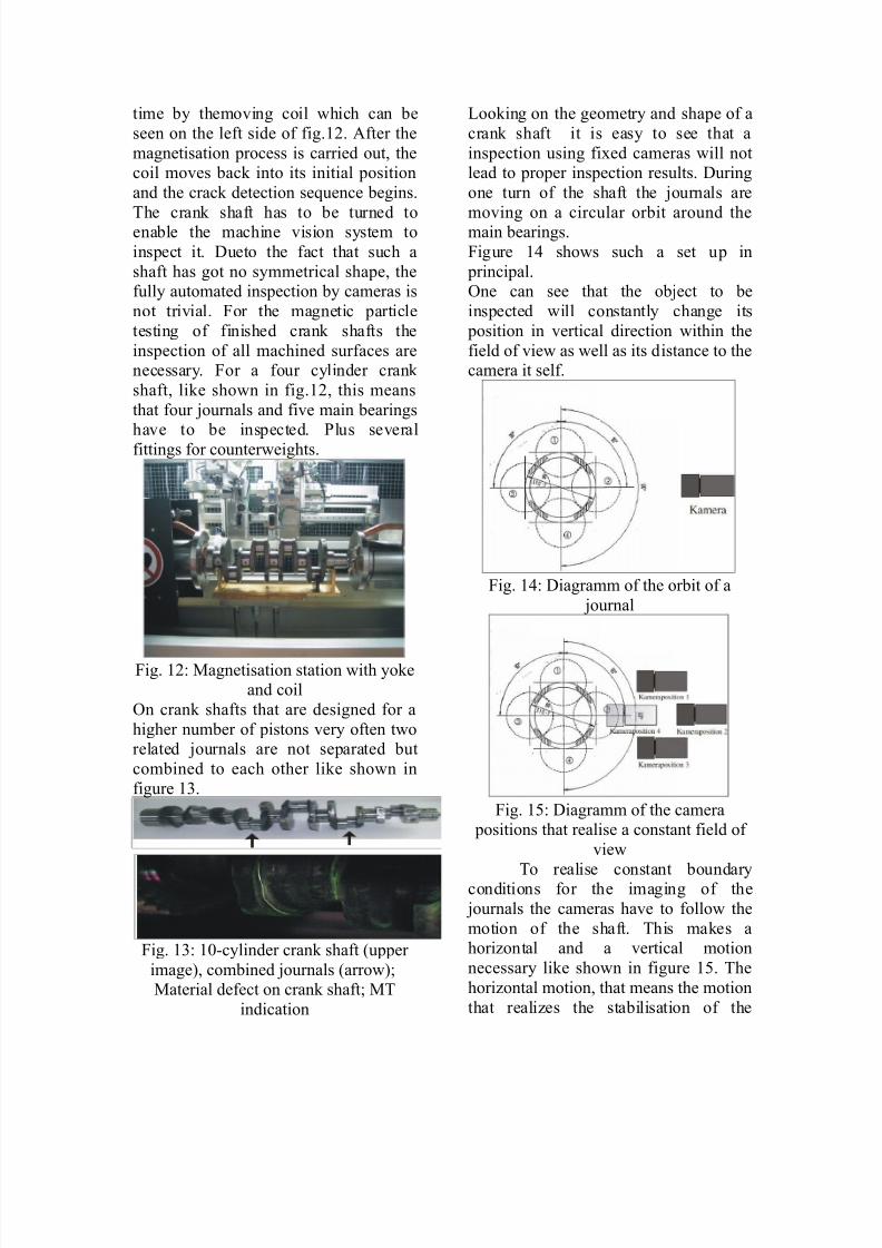
,+ Magneti! testing o" !rank sha"ts
<igure 99 sho$s a fullyautomated and production integrated
magnetic particle crank shaft testing
system. This type of system is in1ermany already used by t$o crank
shaft manufacturing companies.
<ig. 99' %ystem for automated magnetictesting of crank shafts
This system is based on a
magnetisation bench $ith moving coiland turning yokes. The magnetisation
method is a combination of current flo$
for longitudinal and coil magnetisationfor transversal cracks. uring the
magnetisation process# the test li-uid
$ill be applied by a sho$er that is
integrated into the moving coil. <igure9; sho$s the magneti&ation station of
the system. The crank shaft is inserted
into the pneumatic $ork piece holder viaa overhead conveyerthat loads the shaft
through the roof of the darkening booth
into the machine. The $ork piece holder
adAusts the crank shaft in bet$een theyokes that are designed as a clamping
station. fter the yokes closed# the $ork
piece holder $ill release the shaft. Theshaft is no$ only held in position by the
clamping force of the yoke. uring the
magnetisation the crank shaft $ill bemagnetised by the yokes and at the same
8/11/2019 38103 - Muhammad Wisnu C - Electromagnetics C
http://slidepdf.com/reader/full/38103-muhammad-wisnu-c-electromagnetics-c 5/7
time by themoving coil $hich can be
seen on the left side of fig.9;. fter the
magnetisation process is carried out# thecoil moves back into its initial position
and the crack detection se-uence begins.
The crank shaft has to be turned toenable the machine vision system to
inspect it. ueto the fact that such a
shaft has got no symmetrical shape# thefully automated inspection by cameras is
not trivial. <or the magnetic particle
testing of finished crank shafts the
inspection of all machined surfaces arenecessary. <or a four cylinder crank
shaft# like sho$n in fig.9;# this means
that four Aournals and five main bearings
have to be inspected. lus severalfittings for counter$eights.
<ig. 9;' Magnetisation station $ith yokeand coil
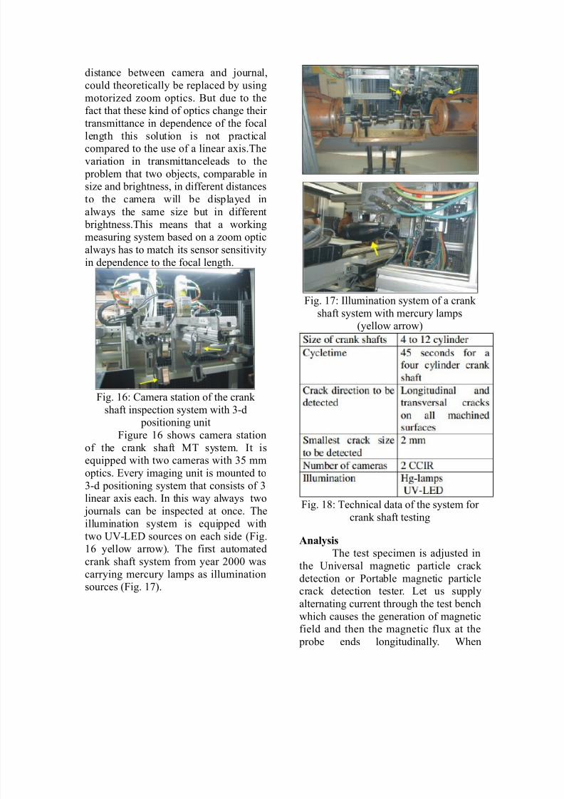
3n crank shafts that are designed for a
higher number of pistons very often t$orelated Aournals are not separated but
combined to each other like sho$n in
figure 96.
<ig. 96' 90cylinder crank shaft (upper
image)# combined Aournals (arro$)BMaterial defect on crank shaftB MT
indication
+ooking on the geometry and shape of a
crank shaft it is easy to see that a
inspection using fi"ed cameras $ill notlead to proper inspection results. uring
one turn of the shaft the Aournals are
moving on a circular orbit around themain bearings.
<igure 9> sho$s such a set up in
principal.3ne can see that the obAect to be
inspected $ill constantly change its
position in vertical direction $ithin the
field of vie$ as $ell as its distance to thecamera it self.
<ig. 9>' iagramm of the orbit of a
Aournal
<ig. 9' iagramm of the camera positions that realise a constant field of
vie$
To realise constant boundaryconditions for the imaging of the
Aournals the cameras have to follo$ the
motion of the shaft. This makes ahori&ontal and a vertical motion
necessary like sho$n in figure 9. The
hori&ontal motion# that means the motion
that reali&es the stabilisation of the
8/11/2019 38103 - Muhammad Wisnu C - Electromagnetics C
http://slidepdf.com/reader/full/38103-muhammad-wisnu-c-electromagnetics-c 6/7
distance bet$een camera and Aournal#
could theoretically be replaced by using
motori&ed &oom optics. Cut due to thefact that these kind of optics change their
transmittance in dependence of the focal
length this solution is not practicalcompared to the use of a linear a"is.The
variation in transmittanceleads to the
problem that t$o obAects# comparable insi&e and brightness# in different distances
to the camera $ill be displayed in
al$ays the same si&e but in different
brightness.This means that a $orkingmeasuring system based on a &oom optic
al$ays has to match its sensor sensitivity
in dependence to the focal length.
<ig. 9' ?amera station of the crank
shaft inspection system $ith 6d
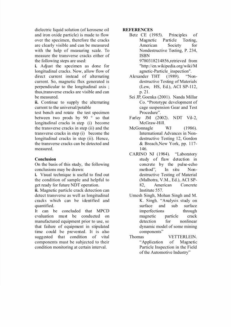
positioning unit<igure 9 sho$s camera station
of the crank shaft MT system. *t ise-uipped $ith t$o cameras $ith 6 mm
optics. 2very imaging unit is mounted to
6d positioning system that consists of 6linear a"is each. *n this $ay al$ays t$o
Aournals can be inspected at once. The
illumination system is e-uipped $ith
t$o !,+2 sources on each side (<ig.9 yello$ arro$). The first automated
crank shaft system from year ;000 $ascarrying mercury lamps as illuminationsources (<ig. 97).
<ig. 97' *llumination system of a crank
shaft system $ith mercury lamps(yello$ arro$)
<ig. 98' Technical data of the system for
crank shaft testing
Anal(sis
The test specimen is adAusted in
the !niversal magnetic particle crack
detection or ortable magnetic particlecrack detection tester. +et us supply
alternating current through the test bench
$hich causes the generation of magneticfield and then the magnetic flu" at the
probe ends longitudinally. @hen
8/11/2019 38103 - Muhammad Wisnu C - Electromagnetics C
http://slidepdf.com/reader/full/38103-muhammad-wisnu-c-electromagnetics-c 7/7
dielectric li-uid solution (of kerosene oil
and iron o"ide particle) is made to flo$
over the specimen# therefore the cracksare clearly visible and can be measured
$ith the help of measuring scale. To
measure the transverse cracks either of the follo$ing steps are used'
i+ dAust the specimen as done for
longitudinal cracks. No$# allo$ flo$ of direct current instead of alternating
current. %o# magnetic flu" generated is
perpendicular to the longitudinal a"is B
thus#transverse cracks are visible and can be measured.
ii+ ?ontinue to supply the alternating
current to the universal5potable
test bench and rotate the test specimen bet$een t$o prods by :0 D so that
longitudinal cracks in step (i) becomethe transverse cracks in step (ii) and the
transverse cracks in step (i) become the
longitudinal cracks in step (ii). 4ence#the transverse cracks can be detected and
measured.
Con!lusion
3n the basis of this study# the follo$ing
conclusions may be dra$n'
i+ ,isual techni-ue is useful to find outthe condition of sample and helpful to
get ready for future NT operation.
ii+ Magnetic particle crack detection candetect transverse as $ell as longitudinal
cracks $hich can be identified and
-uantified.
*t can be concluded that M?evaluation must be conducted on
manufactured e-uipment prior to use# so
that failure of e-uipment in stipulatedtime could be prevented. *t is also
suggested that condition of vital
components must be subAected to their condition monitoring at certain interval.
-E%E-E.CE
Cet& ?2 (9:8). rinciples of
Magnetic article Testing#merican %ociety for
Nondestructive Testing# . ;6>#
*%CN:780698;9>8#retrieved from
Ehttp'55en.$ikipedia.org5$iki5M
agneticarticleFinspectionE.le"ander T4T (9:8:). GNon
destructive Testing of Materials
(+e$# 4%# 2d.)# ?* %99;#
p. ;9.%ei H# 1oenka (;009). Nanda Millar
?o. Grototype development of
cage suspension 1ear and Test
rocedureI.<arley HM (;00;). NT ,il;#
Mc1ra$4ill.Mc1onnagle @H (9:8).
*nternational dvances in Non
destructive Testing 9;# 1ordonJ Creach#Ne$ Kork# pp. 997
9>.
?L*N3 NH (9:8>). G+aboratory
study of fla$ detection inconcrete by the pulseecho
methodI# *n situ Non
destructive Testing of Material(Malhotra# ,.M.# 2d.)# ?* %
8;# merican ?oncrete
*nstitute 7.!mesh %ingh# Mohan %ingh and M.
. %ingh. Gnalysis study on
surface and sub surface
imperfections throughmagnetic particle crack
detection for nonlinear
dynamic model of some miningcomponentsI
Thomas ,2TT2L+2*N.
Gpplication of Magneticarticle *nspection in the <ield
of the utomotive *ndustryI


![[Wisnu,2012]Modul Ols Ivreg](https://img.pdfslide.tips/doc/110x75/557202f44979599169a45706/wisnu2012modul-ols-ivreg.jpg)