Embed Size (px)
Citation preview

IM-P402-93 AB Issue 7 1
LC2610Level Controller
Installation and Maintenance Instructions
IM-P402-93AB Issue 7
4028050/7
�� ����������� ����������
�� �������������� ����������
�� ������� ������������� ������� ��� ��������� ����������
������������� ���������
����������� ���!����� �������
"� ���� �������������#� $����������
% ������ ����&� ������������'� (���� ��������� ������� ��)����� ��������� ����
��! �����
������
������������������
Printed in the UK © Copyright 2004
Archive

IM-P402-93 AB Issue 72
�������������� ������������Your attention is drawn to Safety Information Sheet IM-GCM-10 as well as to anyNational or local regulations.Safe operation of the product depends on it being properly installed, commissionedand maintained by a qualified person in compliance with the operating instructions.It is essential to comply with general installation and safety instructions for pipelineand plant construction, as well as to make proper use of tools and safety equipment.The product is designed and constructed to withstand the forces encounteredduring normal use. Use of the product for any other purpose, or failure to install theproduct in accordance with these Installation and Maintenance Instructions, could causedamage to the product, will invalidate the marking, and may cause injury or fatalityto personnel.
Additional Safety Notes:Level control and level limiting/alarm products in steam boilersProducts /systems must be selected, installed, operated, and tested in accordance with:- Local or National standards and regulations.- Guidance Notes, (Health and Safety Executive PM5 in the UK).- The requirements of Approvals Authorities.- Boiler inspection bodies.- Boiler manufacturer’s specifications.
Two independent low water limiting / alarm systems must be installed on steam boilers.Level probes must be installed in separate protection tubes / chambers, withsufficient clearance between the tips, and earth.
Each probe must be connected to an independent controller. The alarm relaysmust isolate the boiler heat supply at low alarm status.
A high water alarm may be part of the water level control, or a separate system.An independent high water alarm system must be fitted if it is considered a safetyrequirement. In this case, the relays must simultaneously isolate the feedwater supply andthe boiler heat supply at high alarm status. All boiler water limiters/ alarms requireregular functional testing.
A suitable water treatment regime must be used to ensure continuous safe and correctoperation of the control and limiter /alarm systems. Consult the above authoritiesand a competent water treatment company.
WarningIsolate the mains supply before removing the controller back since hazardous voltages willbe exposed on the controller terminals. This product complies with the requirementsof Electromagnetic Compatibility Directive 89 /336 /EEC by meeting the standards of:- EN 61326 : 1997 A1 + A2 Emissions Class B equipment Table 4.- EN 61326 : 1997 A1 + A2 Immunity for Industrial locations Annex A.The following conditions should be avoided as they may create interference abovethe limits specified in EN 61326 (Immunity) if:- The product or its wiring is located near a radio transmitter.- Excessive electrical noise occurs on the mains supply. Power line protectors (ac)
should be installed if mains supply noise is likely. Protectors can combine filtering,suppression, surge and spike arrestors.
- Cellular telephones and mobile radios may cause interference if used withinapproximately 1 metre (39") of the product or its wiring. The actual separation distancenecessary will vary according to the surroundings of the installation and the powerof the transmitter.
If this product is not used in the manner specified by this IMI, then the protectionprovided may be impaired.
Archive

IM-P402-93 AB Issue 7 3
2.1 GeneralThe LC2610 controller is a panel-mounted instrument for controlling the level of conductive liquids.The minimum conductivity when used with the LP20/PA20 is 5 µS/cm or 5 ppm.All options (apart from the voltage) are selected from a menu on the LCD display using the threebuttons on the controller front panel. The buttons are also used to select and set operatingparameters.Direction arrows are displayed, indicating which button to press to select a particular option.Note: For additional information see the LC2610 Technical Information Sheet.
2.2 InputsThe LC2610 controller can accept a signal from a level probe or transmitter and can be configuredto operate with voltage or current devices.Note: The probe must be long enough to sense over the complete level range.The LC2610 incorporates automatic compensation for the 'wave motion' that can occur in steamboilers. (The wave height is measured approximately every 2 minutes and an appropriate deadband is included in the control loop to minimise valve movement). In addition the LC2610 can accept signals from steam and water meters for two and three elementcontrol applications (see Section 3).
2.3 FunctionThe LC2610 compares the signal it receives (from the level probe and steam / water meter) withthe set point selected by the user. It then changes its output signal to control the water level in theboiler or tank.
2.4 OutputsThe LC2610's control signal can be configured / wired to work with a pump or a modulating controlvalve. It also provides relay outputs for high and low level alarms and can provide a 4 - 20 mAretransmission output.
������
������������������
Fig. 1
�����������������������������
Archive

IM-P402-93 AB Issue 74
���� ���������������The LC2610 can be configured to control the level of a boiler, tank or vessel, by operating a pump,valve or solenoid. The following diagrams show some typical applications:-
3.1 On/off control:- Pump control.- Two alarm outputs.- 4 - 20 mA level output.Note: A solenoid valve may be used instead of a pump.
Fig. 2
Archive

IM-P402-93 AB Issue 7 5
3.2 Modulating control:- Modulating valve control using valve motor drive or 4 - 20 mA control signals.- Two alarm outputs.- 4 - 20 mA level output.Note: The 4 - 20 mA level output is only available when the LC2610 is configured for valve motordrive systems.
Fig. 3
Archive

IM-P402-93 AB Issue 76
3.3 Two or three element modulating control:- Modulating valve control using valve motor drive or 4 - 20 mA control signals.- Two alarm outputs.- 4 - 20 mA level output.- Probe mounted in boiler (in protection tube), or in external chamber.- Feedback from steam meter.- Feed forward from water meter.Note: The 4 - 20 mA level output is only available when the LC2610 is configured for valve motordrive systems.
Fig. 4
Archive

IM-P402-93 AB Issue 7 7
���������������������
To change the voltage:- Disconnect the mains supply.- Unplug the two connector sockets from the back of the unit.- Remove the four back panel screws and the panel itself.- Slide out the PCB. The two-way mains switch is fitted on the PCB next to the transformer- Select the required working voltage, (shown on the switch slider).- Refit the PCB, making sure that the two 10-way plugs engage with the sockets on the
display PCB.- Refit the back panel.- Refit the two connector sockets.
FuseThe fuse is next to the mains switch, as shown.
Fuse typeThe controller is fitted with an internal 20 mm cartridge, 100 mA anti-surge (T) fuse. For the ULversion, replacement fuses must be UL recognised to maintain the integrity of the approval.
The controller is supplied with the voltage switch set to 230 V.The controller is suitable for operation at the following voltages (50 - 60 Hz):-
230 V setting 198 V - 264 Vac
115 V setting 99 V - 132 Vac
Fuse type 20 mm cartridge
Fuse rating 100 mA anti-surge (T)
Maximum power consumption 6 VA
Overvoltage category ��
Transformer
Slide switch upfor 115 V supply
20 mm fuse100 mA anti-surge
230
Fig. 5Archive

IM-P402-93 AB Issue 78
����������������������Maximum ambient temperature 55°C (131°F)Minimum ambient temperature 0°C (32°F)Indoor use onlyAltitude up to 2 000 m (6 561 ft)
Humidity Maximum relative humidity 80% for temperatures up to 31°C (87.8°F)decreasing linearly to 50% relative humidity at 40°C (104°F)
Maximum cable length - controller to probe 100 m (330 ft)
The controller must be installed in a suitable industrial control panel or enclosure to provide impactand environmental protection (pollution degree 2).
The protection rating is IP65, but note that this only applies to the front panel. The panel must havea smooth surface to maintain this protection rating. Minimum pollution degree 2.
The back of the case is open and unprotected, so the degree of protection will depend onthe protection rating of the housing used. Additional sealing is also required between the LC2610and the panel to maintain the IP65 rating. LC2610 terminals must be enclosed within the panel.For the UL version, this must be a 'Type 1' enclosure.
The LC2610 fits into a 137 x 67 mm panel cut-out, and is retained by the two clips and screwssupplied:
- Ensure that the panel has sufficient depth to install the LC2610 and its wiring, including thespace required to withdraw the wiring connectors.
- Ensure that there is sufficient clearance at each side of the case to fit the retaining clipsand screws.
- Make a cut-out in the panel (final size to be 137 x 67), and remove any burrs on the cut edgesto allow the unit to seat properly. We recommend that the cut-out is made slightly undersize atfirst, and filed to fit, as there is only a small lip on the LC2610 case.
- Fit the LC2610 into the panel, and slot the side clips into place on the sides of the case.
- Tighten the retaining screws against the back of the panel, but do not over-tighten.
Fig. 6
137 mm
67 mm
140 mm
Archive

IM-P402-93 AB Issue 7 9
Note:Terminals
1, 3, 5 and 7are common.
See CAUTION,Section 6.3.
Closed
4 - 20 mA transmitter output*
4 - 20 mA steam meter input*(optional)
Open
Potentiometer input (1 k ohm)or water flowmeter*
Capacitance probe or 4 - 20mA input.
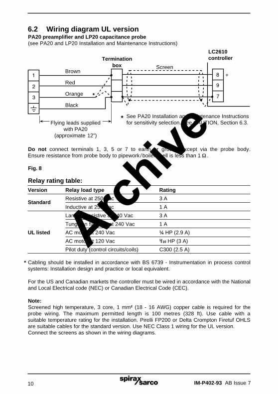
Do not connect terminals 1,3, 5 or 7 to earth or groundexcept via the probe body.Ensure resistance from probebody to pipework /boiler shellis less than 1 �.
Fig. 7 * These units must be isolated from earth.
InputLevel input
+
9
8
7
6
5
4
3
2
1
��� ���������������������!�������������
6.1 General wiring diagram (All relays shown in the power off position)
Note:It is essential to select the correct sensitivity on the PA20 preamplifier, (see the PA20Installation and Maintenance Instructions for details). Tighten the terminals to 0.8 N m(7 lbf in).
High relay alarm
Low relay alarm
Controlrelay
Selectvoltage
internally
Normal
Relay supply
Alarm
Normal
Relay supply
Relay supply
Alarm
Close
Open
N
N
LMains
Control valve electricactuator (valve
motor drive)
20
19
18
17
16
15
14
13
12
11
10
3 A max.
3 A max.
3 A max.
3 A max.Archive
IM-P402-93 AB Issue 710
�
�
�
�
�
Terminationbox Screen
Brown
Red
Orange
Black
Flying leads suppliedwith PA20
(approximate 12")
* See PA20 Installation and Maintenance Instructionsfor sensitivity selection. See CAUTION, Section 6.3.
LC2610controller
6.2 Wiring diagram UL versionPA20 preamplifier and LP20 capacitance probe(see PA20 and LP20 Installation and Maintenance Instructions)
Relay rating table:Version Relay load type Rating
StandardResistive at 250 Vac 3 A
Inductive at 250 Vac 1 A
Lamp or resistive at 240 Vac 3 A
Tungsten fialment at 240 Vac 1 A
UL listed AC motor at 240 Vac ¼ HP (2.9 A)
AC motor at 120 Vac 1/10 HP (3 A)
Pilot duty (control circuits/coils) C300 (2.5 A)
Cabling should be installed in accordance with BS 6739 - Instrumentation in process controlsystems: Installation design and practice or local equivalent.
For the US and Canadian markets the controller must be wired in accordance with the Nationaland Local Electrical code (NEC) or Canadian Electrical Code (CEC).
Note:Screened high temperature, 3 core, 1 mm² (18 - 16 AWG) copper cable is required for theprobe wiring. The maximum permitted length is 100 metres (328 ft). Use cable with asuitable temperature rating for the installation. Pirelli FP200 or Delta Crompton Firetuf OHLSare suitable cables for the standard version. Use NEC Class 1 wiring for the UL version.Connect the screens as shown in the wiring diagrams.
*
Do not connect terminals 1, 3, 5 or 7 to earth or ground except via the probe body.Ensure resistance from probe body to pipework /boiler shell is less than 1 �.
Fig. 8
Archive

IM-P402-93 AB Issue 7 11
6.3 Screen connectionTo avoid damage to the product, screens must be installed as follows:
- An earth current loop is created if a wire or screen is connected between two earth points,which are at different potential (voltage).
- The preamplifier and controller screen are only connected to earth at one end, i.e. at thePA20 earth terminal.
Note: The PA20 earth terminal is a functional earth rather than a protective earth.
- A protective earth provides protection from electric shock under a single fault condition.
- This product has double insulation and therefore does not require a protective earth.
- A functional earth is used in order for the product to operate.
- In this application, the earth (tank /boiler shell) is used as the common of the probe /preamplifier.
- It also provides a sink /drain for any electrical interference.
- Ensure that the screen is connected to the common of the LC2610 (terminal 7) and to theearth terminal of the PA20.
- The LC2610 common terminal is internally isolated from earth.
- The common terminal must only be earthed via the PA20.
CAUTION:Do not connect the common terminals (1, 3, 5 and 7) to an earth local to the controller. Todo so may induce an earth current loop, which may reduce the performance or damage theproduct.
Archive

IM-P402-93 AB Issue 712
6.4 Level inputs - options (All relays shown in the power off position)
Note: It is essential to select the correct sensitivity on the PA20 preamplifier,(see the PA20 Installation and Maintenance Instructions for details).
+ Input
1 2 3
7 8 9Fig. 9PA20 preamplifier (0 - 6 V) input(Links on preamplifier provide sensitivityselection - see the preamplifier IMI formore information).
+ Input
7 8 9
+ -
External power supply18 - 30 V (nominal)
+ Input
7 8 9
+ -
-
+
Fig. 11Externally powered 4 - 20 mA leveltransmitter input
The earth terminal is internally connected tothe PA20 body, and earthed by the LP20probe. Do not connect this earth terminalto any other earths.
Fig. 10Loop powered 4 - 20 mA input(e.g. Two wire differential pressure transmitter)
4 - 20 mA transmitter wiring notes1. Terminals 7, 5, 3 and 1 are linked inside the controller.2. Terminal 8 provides loop power of 18 - 30 Vdc.3. Input resistance between terminals 7 and 9 is 100 �.
LP20 / PA20 wiring notes1. Terminals 7, 5, 3 and 1 are linked inside the controller and are earthed via the
LP20/PA20.2. Terminal 8 provides a drive voltage 18-30 Vdc.3. Input resistance between terminals 7 and 9 is13 k ��
Maximum loopresistance750 �
Archive

IM-P402-93 AB Issue 7 13
6.5 Wiring - on/off control (All relays shown in the power off position)
Note: It is essential to select the correct sensitivity on the PA20 preamplifier,(see Installation and Maintenance Instructions for details).
Note:Terminals
1, 3, 5 and 7are common
20
19
18
17
16
9
8
7
InputLevel input
+ Capacitance probe
Fig. 12
Controlrelay
Selectvoltage
internally
N
N
L
L
Pump contactor
Fuse 3 A max.
3 A max.
Archive

IM-P402-93 AB Issue 714
6.6 Wiring - modulating control with 4 - 20 mA positioner(All relays shown in the power off position)
Note: It is essential to select the correct sensitivity on the PA20 preamplifier,(see Installation and Maintenance Instructions for details). 4 mA always representsvalve closed, and 20 mA represents valve open, regardless of whether 'pump in' or 'pumpout' is selected.
Note:Terminals
1, 3, 5 and 7are common
20
19
9
8
7
4
3
Selectvoltage
internally
Capacitance probe
N
L
4 - 20 mA transmitter outputto positioner card(Max. loop resistance 500 ��
InputLevel input
+
Fig. 13
3 A max.
Archive

IM-P402-93 AB Issue 7 15
20
19
18
17
16
9
8
7
2
1
6.7 Wiring - modulating control(electric actuator with feedback potentiometer)(All relays shown in the power off position)
Note: It is essential to select the correct sensitivity on the PA20 preamplifier,(see Installation and Maintenance Instructions for details).
Note:Terminals
1, 3, 5 and 7are common
Selectvoltage
internally
Capacitance probe
L
N 1
2
4
EL5600 actuatorFill / empty control
Terminal block X 5
1 000 ohm auxiliary feedback potentiometer
Fill / empty control
15
14
16
Terminal block X 4
Fig. 14
Fuse 3 A max.
Input
Level input +
Archive

IM-P402-93 AB Issue 716
6.8 Steam meter input for 2 and 3 element control systemsExternally powered 4 - 20 mA steam flowmeter
CAUTION: Controller terminal 5 (steam meter -ve) may be earthed by level probe.
Resistance between terminals 5 and 6 is 100 ��
6.9 Water meter input for 3 element control systemsCan be used with valve motor drive or 4 - 20 mA positioning.
Externally powered 4 - 20 mA water flowmeter.
CAUTION: Controller terminal 1 (water meter -ve) may be earthed by level probe.
Resistance between terminals 5 and 6 is 100 ��
Fig. 15
5 6
- +
Fig. 16
1 2
- +
Archive

IM-P402-93 AB Issue 7 17
6.10 Alarm relays (All relays shown in the power off position)
Figures 17 and 18 are typical alarm circuit wiring diagrams. The fuse rating must not exceed 3 A. Controller and all relay mains supplies must be on the same phase.
High
Normal Alarm
10 11 12
Burner circuit broken at alarm To alarm lamp or bell
3 A maximum
Relay supply
Low
Normal Alarm
13 14 15
Burner circuit broken at alarm To alarm lamp or bell
3 A maximum
Relay supply
Fig. 17
Fig. 18
Archive

IM-P402-93 AB Issue 718
"��������������������This Section explains how the controller functions are organised and enables the first time userto understand the purpose of the controller modes and settings. These are:-
7.1 Run modeThis is the mode used for normal daily operation, and has two settings:-
AUTO: This is the normal setting used once the controller has been commissioned.
DISPLAY: Used to view the controller settings without making any changes, and bestfor familiarisation.
7.2 Set-up modeThis mode is used for commissioning, and consists of:
ManualAllows the user to take manual control of the valve, and is normally only used duringcommissioning.
ChangeUsed to commission the controller. It allows the controller to be configured to suit the type of input,the type of control, as well as the type of control device (pump or valve) that will be used inthe system. Be careful not to inadvertently make any changes until you understand thesystem layout.
7.3 Using the buttons to select optionsThe display shows the name of the menu on the top line and the available options on the lowerline. A flashing item on the display means that the user has a choice, and may change the menuitem or the setting by pressing one of the buttons. An arrow on the display shows the user whichbutton to press to make a particular change. The status of the unit is shown on the lower line ofthe display at all times - A = Automatic control, M = Manual control.Note:- Some of the diagrams show 'X' instead. This is because either 'A' or 'M' may be displayedon the screen depending on options previously selected.
7.4 Entering the INPUT CODEWhen the controller is switched on for the first time the two digit INPUT CODE (security code) '00'must be entered. This code must be entered each time the controller is used, apart from whenentering display mode. Use the buttons as shown to enter the code.
Note: The display will show the software issue, e.g. '*E' when this menu is entered.
Archive

IM-P402-93 AB Issue 7 19
From page 20'Display settings'
To page 20'Display settings'
From page 24'Changing
settings'
To page 24'Changing
settings'
7.5 Changing the INPUT CODEThe input code may be changed if required, as shown below.
Note 1 :- If the controller is switched off while in MANUAL, an input code will be requested whenthe unit is switched on again. If the controller is switched off while in AUTO, the 'normal operationaldisplay' will appear when the unit is switched on again, and actual control will resume - see below.
Note 2 :- 'xxxxxxxxx' is shown on the diagram below. This will, in reality, show the word 'VALVE'if valve control is selected, 'FLOW' if a water meter is selected, or by 'PUMP ON / PUMP OFF' ifon / off control is selected.
Archive

IM-P402-93 AB Issue 720
The operating modes are accessed as shown in the diagram. Use 'RUN MODE' 'DISPLAY' forfamiliarisation.
Display settings:-
Steam parameters onlydisplayed when steam meter
selected
Archive

IM-P402-93 AB Issue 7 21
The controller is supplied with the following default settings:-
• Security code 00
• Control type Proportional
• Pump action In (boiler water level control, for example)
• Input level 0 - 6 V
• Lvlinput O/rngdet (level input out of range detect) No
• Set point 50 %
• Control band 50 %
• Alarm low 00 %
• High alarm 99 %
• Alarm delay 00 s
• Lockout on alarm No
• Valve drive Relay
• Water meter No
• Steam meter No
Archive

IM-P402-93 AB Issue 722
#��$�����������%������������8.0 'Change' modeThis mode is only used to commission the controller. It allows the controller to be configured tosuit the type of input, the type of control, as well as the type of control device (pump or valve)that will be used in the system.
Note 1 :- If the controller has previously been switched off while in MANUAL, an input code willbe requested when the unit is switched on again. If the controller is switched off while in AUTO,one of the normal operational displays will appear when the unit is switched on again, and actualcontrol will resume.
Note 2 :- 'xxxxxxxxx' is shown on the diagram opposite. This will, in reality, show the word'VALVE' if valve control is selected, 'FLOW' if a water meter is selected, or by 'PUMP ON / PUMPOFF' if on / off control is selected.
Access the 'change' mode as shown in the diagram opposite:-
High alarm 90%
Control band 15%(symmetrical about set point)
Low alarm 10%
100%Absolute maximum
safe water level
57.5%
Set point 50%
42.5%
0%Absolute minimum water level
(water must alwaysbe visible in glass)
Fig. 19 Typical percentages of level settings in a gauge glassConsult the boiler manufacturer for their recommendations
See Section 8.9 for 'Control band'See Section 8.10for 'Alarm low'See Section 8.11for 'Alarm high'
Archive

IM-P402-93 AB Issue 7 23
Press the 'right' button to enter change mode and display the first variable, 'CONTROL TYPE'.
From page 20'Display settings'
To page 20'Display settings'
From page 24'Changing
settings'
To page 24'Changing
settings'
'Change' mode
Archive

IM-P402-93 AB Issue 724
From page19 or 23
To page 25
From page 25
8.1 Changing settingsYou may change any of the following variables by using the buttons. Thesystem will not register any changes you have made until the button is pressedto 'Enter' the information. The system will always show you the last informationthat was entered.i.e:- If 'On / Off' has been entered then this will be displayed instead of 'Prop'when you go back to that menu item.
8.2 Control typeTo select either 'Proportional' control or 'On / Off' control, enter the input codeand select 'Change' as described in Section 8.0.
Choose the option(s) required by following the diagrams below:-
8.3 Pump actionSelect 'In' for boiler feedwater valve, or 'Out' for a condensate tank or similarapplication:-Arch
ive
IM-P402-93 AB Issue 7 25
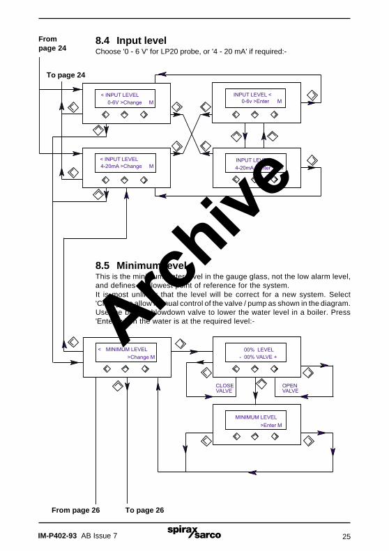
8.4 Input levelChoose '0 - 6 V' for LP20 probe, or '4 - 20 mA' if required:-
To page 26
Frompage 24
To page 24
From page 26
8.5 Minimum levelThis is the minimum water level in the gauge glass, not the low alarm level,and defines the lowest point of reference for the system.It is most unlikely that the level will be correct for a new system. Select'Change' to allow manual control of the valve / pump as shown in the diagram.Use the bottom blowdown valve to lower the water level in a boiler. Press'Enter' when the water is at the required level:-Arch
ive

IM-P402-93 AB Issue 726
Topage 25
To page 27
From page 27
Frompage 25
8.6 Maximum levelThis is the maximum water level in the gauge glass, not the high alarmlevel, and defines the highest point of reference for the system.It is most unlikely that the level will be correct for a new system. Select'Change' to allow manual control of the valve / pump as shown in thediagram. Press 'Enter' when the water is at the required level:-
8.7 Lvlinput O/rngdetLeVeL INPUT Out of RaNGe DETection.If selected, this feature will flash 'ALARM HIGH / ALARM LOW' if theinput signal should fall to below 0.2 V / 2 mA, or exceed 6 volts. It willalso de-energise all relays:-Arch
ive

IM-P402-93 AB Issue 7 27
Frompage 26
To page 28
To page 26
From page 28
8.8 Set pointThis is the point from which the control band is generated.It is commonly set half way between the minimum and maximum gaugeglass levels, though this is not essential:-
8.9 Control bandThis is the proportional band for a modulating control system, or the open / closedswitching points for an on/off system. Its central point is always the 'SET POINT'.When the water level is at the top of the control band, the feedwater valve is fullyclosed, and when the water level is at the bottom of the band, the valve is fully open.Note:- Because the controller has some integral action in 'Proportional' control,the actual position of the valve may not always correspond with the level in thegauge glass.The LC2610 measures the height of any waves in the boiler automatically andcompensates for their action.If possible, follow the boiler manufacturers advice on these levels. If not, asetting of about 15 % is a good starting point for many boilers:-Also see Figure 19, on page 22.Arch
ive

IM-P402-93 AB Issue 728
To page 29From page 29
Topage 27
Frompage 27
8.10 Alarm lowThe low alarm relay is normally wired to sound an alarm, and, in manycases, to switch off the burner. Always consult the boiler manufacturer fora recommended low alarm level.Note:- Additional low level alarms are normally fitted to the boiler.The alarm level is normally set below the lower limit of the 'CONTROLBAND', but above the 'MINIMUM LEVEL':-Also see Figure 19, on page 22.
8.11 Alarm highA high alarm warns that the boiler water level is higher than the manufacturer'sspecified limit, and that consequently, carryover could occur.The high alarm relay will normally be wired to sound an alarm, and sometimes tostop the feedpump.It is possible to wire the system so that the burner is also switched off, but werecommend that the boiler manufacturer is consulted for the preferred option, aswell as to define the high alarm level for the boiler. The alarm level is normally setabove the higher limit of the 'CONTROL BAND', but below the 'MAXIMUM LEVEL':-Also see Figure 19, on page 22.Arch
ive
IM-P402-93 AB Issue 7 29
From page 30
To page 30
Frompage 28
Topage 28
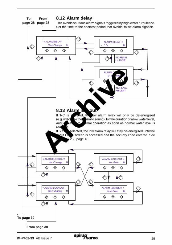
8.12 Alarm delayThis avoids spurious alarm signals triggered by high water turbulence.Set the time to the shortest period that avoids 'false' alarm signals:-
8.13 Alarm lockoutIf 'No' is selected, the low alarm relay will only be de-energised(e.g. will cause the alarm to sound), for the duration of a low water level,and will revert to normal operation as soon as normal water level isreached.If 'Yes' is selected, the low alarm relay will stay de-energised until the'Input Code' screen is accessed and the security code entered. SeeSection 12.2, page 40.Arch
ive

IM-P402-93 AB Issue 730
Note: If the 4 - 20 mA is selected, to drive a valve /positioner, the controller will output20 mA when the water level is at the bottom of the control band, and 4 mA at the top.If an inverse output is required, e.g. for a reverse acting valve, select 'pumping out'.Section 8.3, Pump action.
Note: If the 4 - 20 mA output is not used to drive the valve, the output will represent level withthe following limits:-Minimum level (page 25) = 4 mA (0%)Maximum level (page 26) = 20 mA (100%)
To page 29
From water meter selectionon page 32
8.14 Valve drive / 4 - 20 mA retransmissionSelect either 'Relay' or '4 - 20 mA' to suit the type of drive required:-
To water meter selectionon page 32
From page 29
Archive

IM-P402-93 AB Issue 7 31
8.15 Two and three element control for boilersThese notes are included at this stage because the subsequent display sequence will varyaccording to the selections made:-
Two element controlWhen a sudden increase in steam demand occurs, boiler pressure will drop, and the steambubbles in the water will expand. This causes the water level to rise, and the feedwater valve toclose. Although the measured level of water has increased, the mass of water will be decreasing,requiring the feedwater valve to open. A two element control system (probe / controller and steamflowmeter) uses the output from the steam flowmeter to alter the control action and prevent thevalve closing.
For effective control, it is important to make an accurate assessment of the rise in water level underfull steam flow (maximum demand). This rise in water level can vary according to operatingconditions, for example steady maximum steam demand, or intermittent, sudden demand, as wellas factors such as boiler pressure and water TDS level. There will also be a difference in levelbetween the boiler and the gauge glass under different firing conditions and steam demand.
Three element controlUnder certain conditions where the boiler feedwater pressure varies considerably, perhaps dueto other boilers drawing water, three element control is used. A water flowmeter is added tocompensate for variations in flow due to pressure variations. The diagram shows the selectionsavailable, and how they relate.
8.16 Maximum waterThe water meter needs to be scaled so that it reads 100% at the maximum boiler output.For example, if the maximum boiler capacity is 60% of the maximum on the meter scale,'Enter' 60%.
8.17 Minimum valveThe valve has a feedback potentiometer which tells the controller the valve position. Fully closethe valve (physically check that it is fully closed) then press 'Enter' to calibrate the minimumpotentiometer setting.
8.18 Maximum valveThe valve has a feedback potentiometer which tells the controller the valve position. Fully openthe valve (physically check that it is fully open) then press 'Enter' to calibrate the maximumpotentiometer setting.
8.19 Maximum steamThe steam meter needs to be scaled so that it reads 100% at the maximum boiler output.For example, if the maximum boiler capacity is 60% of the maximum on the meter scale,'Enter' 60%.
8.20 Steam offsetThis is the estimated rise in 'SET POINT' (as a percentage of the gauge glass) which wouldoccur if the boiler output changed from 0 - 100%. A figure of 20% may be a good starting point formany boilers.
For the display sequence see pages 32 to 35.
Archive

IM-P402-93 AB Issue 732
To page 34
From page 30 To page 30
From page 34
Archive

IM-P402-93 AB Issue 7 33
Archive

IM-P402-93 AB Issue 734
������������� �������������
�������������
From page 32To page 32
Archive

IM-P402-93 AB Issue 7 35
� To set-up mode on page 19 or 23
��To set-up mode on page 19 or 23
Archive
IM-P402-93 AB Issue 736
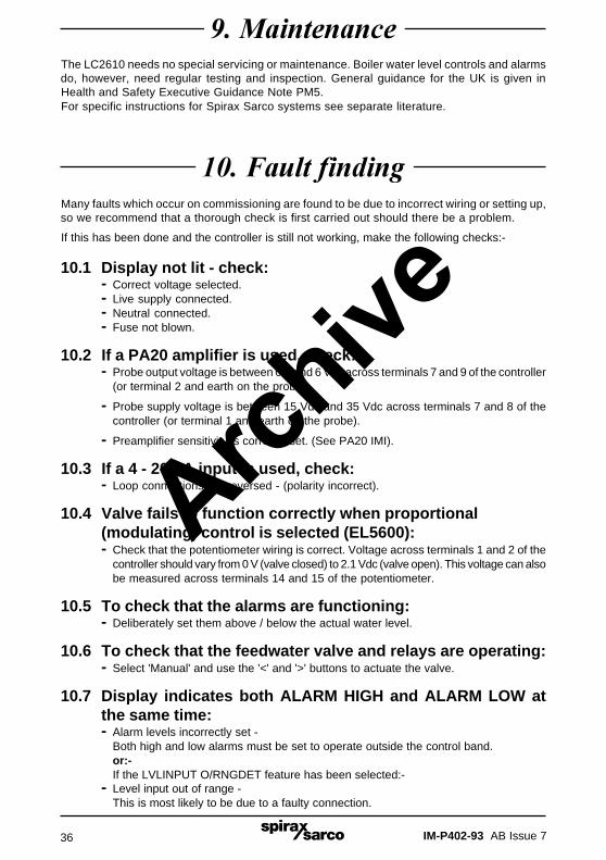
&�������������
Many faults which occur on commissioning are found to be due to incorrect wiring or setting up,so we recommend that a thorough check is first carried out should there be a problem.
If this has been done and the controller is still not working, make the following checks:-
10.1 Display not lit - check:- Correct voltage selected.- Live supply connected.- Neutral connected.- Fuse not blown.
10.2 If a PA20 amplifier is used, check:- Probe output voltage is between 0 V and 6 Vdc across terminals 7 and 9 of the controller
(or terminal 2 and earth on the probe).
- Probe supply voltage is between 15 Vdc and 35 Vdc across terminals 7 and 8 of thecontroller (or terminal 1 and earth on the probe).
- Preamplifier sensitivity is correctly set. (See PA20 IMI).
10.3 If a 4 - 20mA input is used, check:- Loop connections not reversed - (polarity incorrect).
10.4 Valve fails to function correctly when proportional(modulating) control is selected (EL5600):- Check that the potentiometer wiring is correct. Voltage across terminals 1 and 2 of the
controller should vary from 0 V (valve closed) to 2.1 Vdc (valve open). This voltage can alsobe measured across terminals 14 and 15 of the potentiometer.
10.5 To check that the alarms are functioning:- Deliberately set them above / below the actual water level.
10.6 To check that the feedwater valve and relays are operating:- Select 'Manual' and use the '<' and '>' buttons to actuate the valve.
10.7 Display indicates both ALARM HIGH and ALARM LOW atthe same time:- Alarm levels incorrectly set -
Both high and low alarms must be set to operate outside the control band.or:-If the LVLINPUT O/RNGDET feature has been selected:-
- Level input out of range -This is most likely to be due to a faulty connection.
The LC2610 needs no special servicing or maintenance. Boiler water level controls and alarmsdo, however, need regular testing and inspection. General guidance for the UK is given inHealth and Safety Executive Guidance Note PM5.For specific instructions for Spirax Sarco systems see separate literature.
�'��(�����������
Archive

IM-P402-93 AB Issue 7 37
��������������)�This Table shows all changeable options, and enables you to record the security code andsettings you have chosen. It provides a convenient reference should future changes be required.
Changeable options Default settings Your Changes(as supplied) settings
CODE (security code) 00
CONTROL TYPE-Proportional ProportionalOn / off
PUMP ACTION-In (e.g. boiler level control) InOut (e.g. condensate tank)
INPUT LEVEL-0 - 6 V (Level probe) 0-6 V4 - 20 mA (Transmitter)
LVLINPUT O/RNGDET(level input out of range detect)
No
SET POINT 50 %
CONTROL BAND 50 %
ALARM LOW 00 %
ALARM HIGH 99 %
ALARM DELAY 00 s
ALARM LOCKOUT No
VALVE DRIVE-Relay Relay
4 - 20 mA
WATER METER No
STEAM METER No
Archive

IM-P402-93 AB Issue 738
Set point
Control band
Alarm delay
Steam flow
Low alarm
High alarm
Steam offset
No
Enter
Yes
INCREMENTS DIGIT
Change code
’M’
’M or A’
’M or A’’A’
’A’
New code
< Auto Display >Run Mode
> MINPUT CODE
*A
50% LEVEL
50% VALVE
No
Yes
CORRECT ?
AA
���������������������!������12.1 Main menu flow chart
Archive

IM-P402-93 AB Issue 7 39
- Level and Valve +
< Manual Change >Set up Mode
Control type
Pump action
Level input
Min level
< Auto Display >
Run Mode Max level
Out of range
Set point
Control band
Alarm delay
Alarm lockout
Valve drive
Low alarm
High alarm
Water meter
Steam meter
Archive

IM-P402-93 AB Issue 740
�������������������
������ ������ �!"�#���$%
������ ������ �!"�#���$%
! ��&'���()��
*
����#��� (+�#,%�!�%�������$%
&�
&�
-%�
()""�(��.
(+�#,%�/�$%
12.2 Clear alarm lock-out flow chartSee Section 8.13, page 29.
Archive


![Peristilahan dalam Bidang Saintifik - johdec.unimap.edu.my 3 Special Issue/Vol_3SI_2014_7_93.pdfJournal of Human Development and Communication Volume 3 (Special Issue), 2014 [93-113]](https://img.pdfslide.tips/doc/110x75/5d38a08488c9931d5c8c5226/peristilahan-dalam-bidang-saintifik-3-special-issuevol3si2014793pdfjournal.jpg)