Embed Size (px)
Citation preview

8/11/2019 5 DSP-ADC-DAC
http://slidepdf.com/reader/full/5-dsp-adc-dac 1/4
1
5: Digital Signal Processing T P Chaturvedi, RCD-----------------------------------------------------------------------------------------------------------------------------------------Introduction:
The world of science and engineering is full of signals. Digital Signal Processing (DSP) is thescience of using computers to understand these types of signals. DSP is widely replacing analogsystems due to its reliability, repeatability and programmability. DSP instruments use the Fast FourierTransform (FFT) to translate digitized time domain signals into the frequency domain for thepurpose of measurement and analysis.
Analog to Digital Converter: ADC converts a signal which is continuous in time and amplitude into
one that is discrete in time and amplitude. The ADC is specified for Input Range, Resolution,Quantization Error, Conversion speed, Sampling Rate etc.
Input Range: The maximum analog voltage which can be applied to input of ADC for the conversion.
Resolution & Quantization: An ideal ADCrepresents all analog inputs within a certain
range by a limited number of digital outputcodes. The diagram shows that each digitalcode represents a fraction of the total analoginput range. Since the analog signal may becontinuous, while the digital codes arediscrete, there is quantization process thatintroduces a quantization error.
The analog samples are quantized andmapped into their nearest digital value. For example, a 4 bit ADC can represent ananalog sample as one of 16 possible valuesi.e. (2
4 = 16). If the range of this converter is
0 and 10 volts, then its resolution is 10/(24
-1)= 0.667 volts/bit.
The width of one step is defined as 1 LSB(least significant bit). It is also a measure ofthe resolution of the converter since it defines the number of divisions or units of the full analog range.The resolution of an ADC is usually expressed as the number of bits and is improved byincreasing it. For example, an ADC with an n-bit resolution has 2
n possible digital codes which define
2n step levels. However, since the first (zero) step and the last step are only one half of a full width,
the full-scale range (FSR) is divided into 2n – 1 step widths. 1LSB=FSR/ (2
n –1) for an n-bit ADC.
Pre-condition Anti-aliasing Filter
Sampling Quantization

8/11/2019 5 DSP-ADC-DAC
http://slidepdf.com/reader/full/5-dsp-adc-dac 2/4
2
Quantizing Noise: Quantizing noise is introduced inthe process of converting the analog signal to digitalvalue. Quantizing noise is basically due to the finiteresolution of ADC. The two main variables inquantizing are the quantization level and dynamicrange.
For any input within the dynamic range of thedigitizer, the output will be a digital representation ofthe input, to the nearest integral multiple of thequantization level. Now this noise or error introducedby the quantization depends on the relative intensity ofthe noise in the original signal with respect to the sizeof the quantization level. The Standard deviation of
the quantization noise is V/ 12, where V is themagnitude of quantization level in volts.
Sampling: In order to convert an analog signal into a digital code, it must first be sampled. Thisresults in natural sample values which remain continuous in amplitude but discrete in time. Thesample values are exactly equal to the original signal value at the sampling instant. The amplitude ofthe analog signal is measured at discrete points in time using a sample and hold circuit.
Nyquist Sampling Theorem: Nyquist Sampling Theorem states that a signal must be sampled at arate that is twice the highest frequency component in the signal. In other word, if the sampling rateis 1/∆t (sampling interval =∆t), the Fourier transform of the signal must be zero at all the frequenciesgreater than 1/(2∆t). The critical frequency, Fn=1/(2∆t), is called Nyquist frequency. A signal withFourier components from 0 to 300 Hz should sampled at a rate of at least 600 samples per second orevery 1.7 msec.Under sampling and Alias frequency: If thesignal is under sampled there will be errors inreconstruction of the signal back.. These errorswill manifest in two ways. The frequencyinformation above the nyquist frequency willbe lost and under sampled high frequency
show up as spurious low frequency called asaliasing. If the analog signal is under sampled,signal reconstructed will have lower aliasingfrequencies not present initially. Here we have a100 Hz sine wave sampled at 80 Hz i.e. less than 2 * fmax and as a consequence the reconstructedsignal could also be as 20 Hz.
This effect is known as aliasing, and iscombated by first ensuring the sampling rate ishigh enough and secondly through the use of ananalog low pass filter in front of the ADC. Thisfilter is called an anti-aliasing filter. Anti-aliasing filterensures that any frequency components which couldcause aliasing are suppressed.
Differential Non Linearity (DNL) is defined as maximum amount of deviation of any quantum ( orLSB change) in entire transfer function from it’s ideal size of FS/2
n
Differential Non Linearity (DNL) is defined as maximum amount of deviation of any quantum ( orLSB change) in entire transfer function from it’s ideal size of FS/2
n
Analog-to-digital converter:
8/11/2019 5 DSP-ADC-DAC
http://slidepdf.com/reader/full/5-dsp-adc-dac 3/4
3
Flash ADC: Also called the parallel A/D converter. It isformed of a series of comparators, each one comparing theinput signal to a unique reference voltage. The comparatoroutputs connect to the inputs of a priority encoder circuit,which then produces a binary output. For N bit ADC 2
N-1
comparators are required.
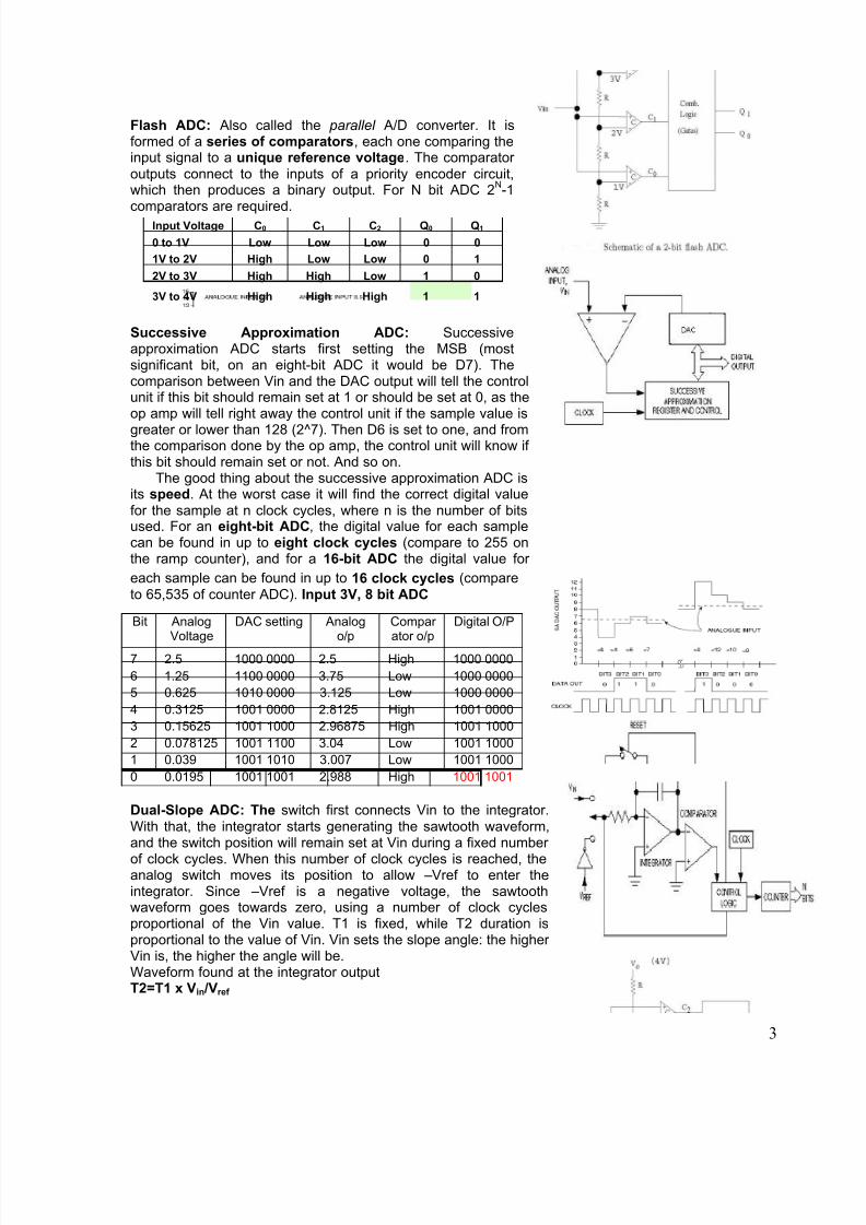
Successive Approximation ADC: Successiveapproximation ADC starts first setting the MSB (mostsignificant bit, on an eight-bit ADC it would be D7). Thecomparison between Vin and the DAC output will tell the controlunit if this bit should remain set at 1 or should be set at 0, as theop amp will tell right away the control unit if the sample value is
greater or lower than 128 (2^7). Then D6 is set to one, and fromthe comparison done by the op amp, the control unit will know ifthis bit should remain set or not. And so on.
The good thing about the successive approximation ADC isits speed. At the worst case it will find the correct digital valuefor the sample at n clock cycles, where n is the number of bitsused. For an eight-bit ADC, the digital value for each samplecan be found in up to eight clock cycles (compare to 255 onthe ramp counter), and for a 16-bit ADC the digital value for
each sample can be found in up to 16 clock cycles (compareto 65,535 of counter ADC). Input 3V, 8 bit ADC
Dual-Slope ADC: The switch first connects Vin to the integrator.With that, the integrator starts generating the sawtooth waveform,and the switch position will remain set at Vin during a fixed number
of clock cycles. When this number of clock cycles is reached, theanalog switch moves its position to allow –Vref to enter theintegrator. Since –Vref is a negative voltage, the sawtoothwaveform goes towards zero, using a number of clock cyclesproportional of the Vin value. T1 is fixed, while T2 duration isproportional to the value of Vin. Vin sets the slope angle: the higherVin is, the higher the angle will be.Waveform found at the integrator outputT2=T1 x Vin /Vref
Input Voltage C0 C1 C2 Q0 Q1
0 to 1V Low Low Low 0 0
1V to 2V High Low Low 0 1
2V to 3V High High Low 1 0
3V to 4V High High High 1 1
Bit AnalogVoltage
DAC setting Analogo/p
Compar ator o/p
Digital O/P
7 2.5 1000 0000 2.5 High 1000 0000
6 1.25 1100 0000 3.75 Low 1000 0000
5 0.625 1010 0000 3.125 Low 1000 0000
4 0.3125 1001 0000 2.8125 High 1001 0000
3 0.15625 1001 1000 2.96875 High 1001 1000
2 0.078125 1001 1100 3.04 Low 1001 1000
1 0.039 1001 1010 3.007 Low 1001 1000
0 0.0195 1001 1001 2.988 High 1001 1001

8/11/2019 5 DSP-ADC-DAC
http://slidepdf.com/reader/full/5-dsp-adc-dac 4/4
4
Weighted Resistor Digital to Analog Converter (DAC)
A switch connects an input either to a common voltage V
or to a common ground. Only switches currently
connected to the voltage source contribute current to the
non-inverting input summing node. SX = 1 if switch Xconnects to V, SX = 0 if it connects to ground.
There are eight possible combinations of connections for
the three switches. The inputs are weighted in a 4:2:1
relationship, so that the sequence of values 4S3 + 2S2 +
S1 form a binary-coded decimal number representation.The magnitude of Vo varies in units (steps) of (R
f /4R)V
from 0 to 7. The digital input controls the switches, and the
amplifier provides the analog output.
The converter uses only one resistor per bit. Matching the resistors is critical to achieve linearity is
disadvantage. This type of converter is most often used where only a few bits, say 4 or 6, are requiredand performance is not critical.
R-2R Ladder DACIt solves problem of the weighted resistor converter since it uses
only two resistor values the matching is considerably easier to
achieve, making it easy to integrate on an IC.
A three-section R-2R ladder is connected to a switch network so
that either a fixed voltage V is applied to each section or a ground
connection is made. The current contribution through each switch
(apply superposition) is as given. Sx is a binary variable which has
the value 1 is the voltage connection is made, and the value 0 for
a ground connection.
The current from the ladder is fed to an inverting amplifier, and the output voltage Vo is
Vo = -Rf (1 1 1
3 2 1 )3 2 3 4 3 8
V V V S S S
R R R = -R f
24
V
R (4 3 2 2 1)S S S
ADC Advantage Disadvantage
Flash Type Low conversion time (~20 ns )
For N bit ADC 2 -1comparator
required, Large DNLSuccessiveapproximation
Conversion time <10µsHigh Resolution
Poor linearity( ±1/2LSB)
Dual Slope ADC Excellent linearity,Good noise rejection
Slow speed


![24bit 3ch ADC +4ch DAC + Mic Amp Audio DSP · [ak7757] ms1489-j-01-pb 3 2013/05 オーダリングガイド ak7757vq -40 ∼ +85°c 48pin lqfp akd7757 ak7757評価ボード ピン配置図](https://img.pdfslide.tips/doc/110x75/5af1ad027f8b9ac62b90472f/24bit-3ch-adc-4ch-dac-mic-amp-audio-dsp-ak7757-ms1489-j-01-pb-3-201305-.jpg)