Embed Size (px)
Citation preview

1804 05H.EA293
6000SLXSL-T
6000SLXSL-T
HYDRAULIC CRAWLER CRANE

Contents
Specifications
Symbols
Outline
………………………………………………………………………………………………… 4
Winch Assignment ……………………………………………………………………… 5 Dimensions & Main Specifications : Liftcrane ……………………………………… 6 Dimensions & Main Specifications : Luffing Tower ………………………………… 7
……………………………………………………………………………………………… 3-4
Liftcrane Heavy Duty Boom
Boom Combinations …………………………………………………………………… 8 Working Range Diagram ……………………………………………………………… 8 Capacities ……………………………………………………………………………… 9 Notes ……………………………………………………………………………… 10-11
Liftcrane Long Range Boom
Boom Combinations ………………………………………………………………… 12 Working Range Diagram ……………………………………………………………… 12 Capacities ……………………………………………………………………………… 13 Notes ………………………………………………………………………………… 14-15
Transport Data …………………………………………………………………………………………… 30-31
Boom Combinations …………………………………………………………… 16-17 Working Range Diagram …………………………………………………………… 18-22 Capacities ………………………………………………………………………… 23-27 Notes ……………………………………………………………………………… 28-29
6000SLX SL-T Specifications
Luffing Tower

HYDRAULIC CRAWLER CRANE 6000SLXSpecifications
3
Engine
Model : Isuzu 6WG1
Type : 4-cycle, water-cooled, direct injection, turbo-charged, diesel engine
Displacement : 15 681 cc
Rated Output : 397 kW / 1 800 min-1 (540 ps / 1 800 rpm)
Fuel Tank : 800 liters
Electrical System : 24 V D.C., 2 batteries
Notes:1 Engine meets Stage / Tier 3 of current smoke emission
regulations in Europe, United States and Japan. 2 The 397 kW engine horsepower shown above is based
on an international engine horsepower rating formula that includes the horsepower necessary for engine alternator drive but excludes engine fan drive.
Control
Control System : Control levers operate remote-controlled hydraulic servos that direct oil through six sets of tandem valves to provide comprehensive motion control.
Control Levers : Ergonomic lever layout enables efficient operation. Joystick lever on left side controls slewing and boom hoist. Arm-chair levers on right side control hoist 1 & 2, luffing jib hoist, travel and long-mast hoist. Main winch levers are equipped with drum rotation sensors.
Slewing Brake Pedal:
Designed to be maintenance free while resisting overheating. Unique brake design of hydraulic oil control system makes it possible to smoothly initial slewing motion, even against the wind.
Display Panel Design :
Graphics on the display panel makes it easy to input the necessary operating conditions and data according to actual lifting and working conditions.
Hydraulic System
Three variable-displacement axial piston pumps and one fixed-displacement tandem gear pump provide power for independent and combined operations for all functions.
Hydraulic Reservoir Capacity : 800 liters
Load Hoist Drums (W1, W2)
Independent bi-directional hydraulic motors provide power through a two-stage planetary reduction gear unit to drive the two main hoisting drums for hoisting and lowering operations. Cables : 28mm dia. / 800 m long.
Long Mast Hoist Drum (W3)
A single bi-directional axial piston hydraulic motor powers a 3-stage planetary reduction gear unit that drives the rope drum to either hoist or lower the long mast. Cables : 28 mm dia.
Luffing Jib Hoist Drum (W4)
A single bi-directional axial piston hydraulic motor powers a 3-stage planetary reduction gear unit that drives the rope drum to either hoist or lower the luffing jib. Cables : 28 mm dia.
Boom Hoist Drum (W5) A single bi-directional axial piston hydraulic motor powers a 3-stage planetary reduction gear unit that drives the rope drum to either hoist or lower the boom. Cables : 28 mm dia.

Symbols
Specifications
HYDRAULIC CRAWLER CRANE 6000SLX
4
Capacity Heavy Duty Boom
Working Radius Heavy Duty Boom Length
Counterweight Long Range Boom
Lower Weight Long Range Boom Length
SL-N Luffing Jib
SL-T Luffing Jib Length
Slewing System
Slewing system is designed so that the three slewing pinions mesh with the external slewing ring gear. With this design, the external slewing gears bears the majority of the slewing torque. The system is designed to be easy to lubricate.
Counterweight
Standard 160 ton counterweight consists of a 20-ton base weight and 14 cast iron block pieces that all have the same dimensions.
Lower Weight
A 62 ton lower weight is required for SL-T specification.
Side Frames
All welded structures are manufactured from high-strength steel. Each component is equipped with two steel plate hooks to make assembling on lower frame lower. Side frame is secured by removable joint pins provided on the lower frame.
Shoe width : 1 220 mm wide is standard.1 524 mm wide is option.
Drive unit : 2-track drive unit per side frame.
Safety Device
Load Moment Indicator (LMI) :
The computerized system helps prevent overloads and provide safe and efficient control. Meets both EN and BS standards.
Front-end Attachment. Erection Mode :
This is an internal function of the Load Moment Indicator (LMI). It gives a warning on the LMI panel that the crane has extended beyond its intended working area. Once the work outside the intended working area is completed, the system returns automatically to resume work in the intended working range.
Hydraulic Boom Backstops :
These stops operate in conjunction with LMI to help prevent backward reaction, especially when operating with short boom lengths or against winds.
Boom Over-hoist and Over-lowering Limiting Device :
This is a combination of two systems designed to enhance operating efficiency. One system is a limit switch that is incorporated into the boom foot to prevent over hoisting. The other is a part of the LMI that prevents over-hoisting or over-lowering the boom. It includes automatic drum braking, hydraulic locks and alarm warnings.
Drum Locks : Electrically operated pawl locks are provided as standard on all drums.

( )W1
W1
+ W2
W2
( )W1
W1
+ W2
W2
W1W5
W3
W5
W2
W4
W5
W3
W5W1
W2
W4
Liftcrane Luffing Tower
Outline / SL-T
Hook BlocksHook blocks Mass (kg)
550 t 280 t hook block plus a ten sheaves egualizer block 12 500280 t Ten sheaves 7 000320 t 160 t hook block plus an eight sheaves equalizer block 7 900160 t Five sheaves 3 90065 t Two sheaves * 3 000 / 2 00015 t Ball hook 950
Winch Assignment
* : With auxiliary weights / Without auxiliary weights
5

Outline 6000SLX
Main Specification. : Liftcrane
* Including basic boom, hook block(H : 550 t hook block, L : 320 t hook block), counterweight(160 t), pallet (w/o External counterweight) and optional 1 524mm wide shoes.
Front-end Attachment DescriptionSpecification
Heavy Duty Boom Long Range Boom
Liftcrane
Max. Lifting Capacity t X m 550 X 8.0 231 X 24.0Basic Boom Length m 36 78Max. Boom Length m 96 126
Line SpeedLoad Hoist Drum : W1, W2 m/min 110Boom Hoist Drum : W5 m/min 40
Slewing Speed min-1(rpm) 1.0 (1.0)Travel Speed km/hr 1.5 / 1.3 / 0.6Ground Pressure* kPa(kgf/cm²) 147 (1.50) 151 (1.54)Working Mass* t 465 477
Dimensions : Liftcrane
H:3
6 0
00
96 0
00
L:7
8 0
00
126 0
00
11 000
13 500
16 000
1 800 1 8003 540
R13 400
(11 m)
R15 900
(13.5 m)
R18 400
(16 m)
7 500
3 600
Dimensions & Main Specifications : Liftcrane
6
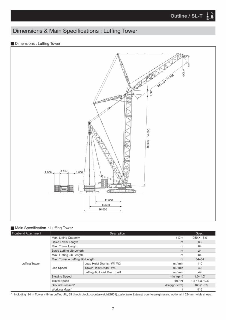
Main Specification. : Luffing Tower
* : Including 84 m Tower + 84 m Luffing Jib, 65 t hook block, counterweight(160 t), pallet (w/o External counterweights) and optional 1 524 mm wide shoes.
Dimensions : Luffing Tower
Front-end Attachment Description Spec.Max. Lifting Capacity t X m 250 X 18.0Basic Tower Length m 36Max. Tower Length m 84Basic Luffing Jib Length m 24Max. Luffing Jib Length m 84Max. Tower + Luffing Jib Length m 84+84
Luffing TowerLine Speed
Load Hoist Drums : W1,W2 m / min 110Tower Hoist Drum : W5 m / min 40Luffing Jib Hoist Drum : W4 m / min 49
Slewing Speed min-1(rpm) 1.0 (1.0)Travel Speed km / hr 1.5 / 1.3 / 0.6Ground Pressure* kPa(kgf / cm²) 163 (1.67)Working Mass* t 516
36 0
00
84 0
00
24 000
84 000
1 5
00
11 000
13 500
16 000
1 800 1 8003 540
Dimensions & Main Specifications : Luffing Tower
Outline / SL-T
7

Liftcrane : Heavy Duty Boom 6000SLXBoom Combinations
5.5m
5.3m
4.5m
16
20
24
28
36
40
44
48
52
56
60
64
68
72
76
80
4 8 12 16 20 24 3228 36
550 t / 280 t 320 t / 160 t 65 t 15 t
40 44 48 52 56 60
84
88
92
96
100
64 68 72
42m
48m
54m
60m
66m
72m
78m
84m
90m
0
104
108
83.5°
Aux. sheave
Working radius (m)
70° 60°
40°
30°
96m
50°
4.0m
1.7m
2.71
m(3
.06m
)
76 80 84 88
8
4
36m
12
32
Hei
ght a
bove
gro
und
(m)
Working Range Diagram
H12AH6AHB9.5 HR7 HT1.5
H12BH12AHB9.5 HR7 HT1.5
H12BH6A H12AHB9.5 HR7 HT1.5
H12CH12A H12BHB9.5 HR7 HT1.5
H12CH12AH6A H12BHB9.5 HR7 HT1.5
HL12BH12BH12A H12CHB9.5 HR7 HT1.5
HL12BH12BH12AH6A H12CHB9.5 HR7 HT1.5
HL12BH12CH12BH12A HL12BHB9.5 HR7 HT1.5
HL12BH12CH12BH12AH6A HL12BHB9.5 HR7 HT1.5
HL12BH12CH12BH12A HL12B HL12BHB9.5 HR7 HT1.5
HL12BH12CH12BH12AH6A HL12B HL12BHB9.5 HR7 HT1.5
Boom Combinations
36 m
42 m
48 m
54 m
60 m
66 m
72 m
78 m
84 m
90 m
96 m
8
( ) w / optional T.T.B. quick disconnect device

Liftcrane : Heavy Duty Boom / SL-T
9
(ton)
160 t 62 t 260 t / 16 m
SL-T H Boom Lifting Capacities
36 ※ 42 48 54 60 66 72 78 84 90 96
7.3 *550.0 8 *550.0 *458.0 *412.0 / 8.79 *528.0 *458.0 *412.0 *364.0 / 9.4
10 *509.0 *458.0 *412.0 *364.0 *339.0 *313.0 / 10.7 *274.0 / 11.412 478.0 452.0 *412.0 *364.0 *339.0 *313.0 *274.0 *223.5 / 12.1 *188.0 / 12.7 *155.5 / 13.414 429.0 431.5 412.0 364.0 *339.0 *313.0 *274.0 *223.5 *188.0 *155.5 *130.5 / 14.116 374.5 379.5 377.5 364.0 339.0 313.0 *274.0 *223.5 *188.0 *155.5 *130.0 18 332.0 336.5 334.5 334.0 333.0 313.0 274.0 *223.5 *188.0 *155.5 *130.0 20 298.0 301.5 300.0 299.0 298.0 299.0 274.0 *223.5 *188.0 *155.5 *130.0 22 268.0 273.0 271.0 270.5 269.5 270.5 270.0 223.5 *188.0 *155.5 *130.0 24 243.5 247.5 246.0 245.0 244.0 245.0 244.5 223.5 188.0 *155.5 *130.0 26 223.0 226.5 224.5 224.0 223.0 224.0 223.0 223.0 188.0 *155.5 *130.0 28 203.2 208.5 206.5 206.0 204.5 205.5 205.0 204.5 188.0 154.5 *130.0 30 184.3 193.0 191.0 190.0 189.0 190.0 189.5 189.0 188.0 151.0 *129.0 32 167.4 179.5 177.5 176.5 175.5 176.0 175.5 175.0 174.5 147.0 126.0 34 154.9 / 33.6 165.2 165.7 164.8 163.7 164.4 163.7 163.3 162.4 143.4 122.5 36 151.7 155.2 154.3 153.1 153.7 153.0 152.6 151.7 139.3 118.9 38 139.4 145.8 144.9 143.6 144.2 143.5 143.1 142.1 135.1 115.3 40 134.6 / 38.8 137.5 136.5 135.2 135.7 134.9 134.5 133.5 131.0 111.8 42 127.4 128.9 127.5 128.0 127.2 126.8 125.8 125.5 108.2 44 117.9 122.1 120.6 121.0 120.2 119.7 118.7 118.4 104.5 46 116.9 114.4 114.6 113.8 113.3 112.3 112.0 101.1 48 109.0 108.7 108.9 108.0 107.5 106.5 106.1 98.3 50 104.4 / 49.2 103.5 103.6 102.6 102.1 101.1 100.7 94.9 52 98.7 98.7 97.7 97.2 96.1 95.8 91.7 54 93.7 94.2 93.2 92.6 91.6 91.2 88.5 56 92.5 / 54.4 90.1 89.0 88.4 87.3 86.9 85.4 58 86.3 84.9 84.5 83.4 83.0 82.1 60 83.0 / 59.6 81.0 80.8 79.6 79.1 78.1 64 74.0 73.7 72.4 71.9 70.9 68 72.7 / 64.8 67.5 66.1 65.6 64.5 72 64.8 / 69.9 60.6 60.1 58.9 76 56.8 / 75.1 55.1 53.9 80 50.7 49.5 84 50.4 / 80.3 45.5
85.5 44.1
(m)
(m)
※ The mass of the counterweight is 140 t when the boom length is 36 m.

10
1. Capacities included in these charts are the maximum allowable, and are based on machine standing level on firm supporting surface under ideal job conditions.
2. Capacities are in metric tons, and are rated in accordance with European EN13 000 Standards in terms of machine stability and structural strength limitations. ; each rated load capacity is based on machine's structural strength limitations.
3. Capacities are based on freely suspended loads and make no allowance for such factors as the effect of wind, sudden stopping of loads, supporting surface conditions, and operating speeds. Operator must reduce load ratings to take such conditions into account. Deduction from rated capacities must be made for weight of hook block, weighted ball/hook, sling, spreader bar, or other suspended gear.
4. The maximum rated load of the auxiliary sheave is the value remaining after the 2.0 ton mass of the auxiliary sheave and the mass of the “main hook” attached to the “boom” are deducted from the maximum rated load of the “Heavy Duty Boom Capacities.”
However, the maximum rated load of the auxiliary sheave is limited to 60 tons. The operating range of the auxiliary sheave is the range that has the maximum rated load of the main hook.
5. If the auxiliary sheave is attached, the maximum rated load of the “main hook” is the value remaining after the 2.0 ton mass of the auxiliary sheave and the mass of the auxiliary hook attached to the auxiliary sheave are deducted from the maximum rated load of the “Heavy Duty Boom Capacities.”
6. The "working radius" is the horizontal distance from the slewing center to the center of gravity of a lifted load.7. The boom tilt angle range is according to the working range diagram. 8. The chart below shows the number of reeled lines and the maximum rated loads. (When the wire rope length is 800 m. )
Notes
Hook Capacity (ton)
Hook Weight (ton)
Maximum Rated Load ( ton )
20 X 2Falls
19 X 2Falls
18 X 2Falls
17 X 2Falls
16 X 2Falls
15 X 2Falls
14 X 2Falls
13 X 2Falls
12 X 2Falls
11 X 2Falls
10 X 2Falls
9 X 2Falls
8 X 2Falls
7 X 2Falls
6 X 2Falls
5 X 2Falls
550Double-Reeling
12.5 550 502 480 458 435 412 388 364 339 314 288 262 235 208 180 - - - - -
320Double-Reeling
7.9 - - - - - - - - 320 314 288 262 235 208 180 151 - - - -
20 Falls
19 Falls
18 Falls
17 Falls
16 Falls
15 Falls
14 Falls
13 Falls
12 Falls
11 Falls
10 Falls
9 Falls
8 Falls
7 Falls
6 Falls
5 Falls
4 Falls
3 Falls
2 Falls
1 Fall
280Single-Reeling
7.0 262 251 240 229 217 206 194 182 170 157 144 131 118 104 - - - - - -
160Single-Reeling
3.9 - - - - - - - - - 157 144 131 118 104 90 76 - - - -
65Single-Reeling
*3.0 / 2.0 - - - - - - - - - - - - - - - 65 61 46 31 -
15Single-Reeling
1.0 - - - - - - - - - - - - - - - - - - - -
Hook Capacity (ton)/Boom Length (m) 36 42 48 54 60 66 72 78 84 90 96
550 Double-ReelingMax. 20 x 2 17 x 2 15 x 2 13 x 2 12 x 2 11 x 2 10 x 2 8 x 2 7 x 2 6 x 2 -
Min. 6 x 2 6 x 2 6 x 2 6 x 2 6 x 2 6 x 2 6 x 2 6 x 2 6 x 2 6 x 2 -
320 Double-ReelingMax. 12 x 2 12 x 2 12 x 2 12 x 2 12 x 2 11 x 2 10 x 2 8 x 2 7 x 2 6 x 2 5 x 2
Min. 5 x 2 5 x 2 5 x 2 5 x 2 5 x 2 5 x 2 5 x 2 5 x 2 5 x 2 5 x 2 5 x 2
280 Single-ReelingMax. 20 17 15 13 12 11 10 8 8 7 7
Min. 7 7 7 7 7 7 7 7 7 7 7
160 Single-ReelingMax. 11 11 11 11 11 11 10 8 8 7 7
Min. 5 5 5 5 5 5 5 5 5 5 5
65 Single-ReelingMax. 5 5 5 5 5 5 5 5 5 5 5
Min. 2 2 2 2 2 2 2 2 2 2 2
15 Single-Reeling - - - - - - - - - - -
9. The chart below shows the operable windings based on the length of each boom.
Liftcrane : Heavy Duty Boom 6000SLX
* :With auxiliary weights / Without auxiliary weights

11
Notes
10. If the total mass of the hook mass and the mass of all rigging components is lighter than the mass indicated on this chart, the hook may not lower even when a lowering operation is performed. Please select a hook that can be lowered based on the boom length and number of windings.
Boom Length / Number of reeled lines
1 Fall
2 Falls
3 Falls
4 Falls
5 Falls
6 Falls
7 Falls
8 Falls
9 Falls
10 Falls
11 Falls
12 Falls
13 Falls
14 Falls
15 Falls
16 Falls
17 Falls
18 Falls
19 Falls
20 Falls
36 m - 2.0 2.0 2.0 2.0 3.9 3.9 3.9 3.9 3.9 3.9 7.0 7.0 7.0 7.0 7.0 7.0 7.0 7.0 7.0
42 m - 2.0 2.0 2.0 2.0 3.9 3.9 3.9 3.9 3.9 3.9 7.0 7.0 7.0 7.0 7.0 7.0 - - -
48 m - 2.0 2.0 2.0 2.0 3.9 3.9 3.9 3.9 3.9 3.9 7.0 7.0 7.0 7.0 - - - - -
54 m - 2.0 2.0 2.0 2.0 3.9 3.9 3.9 3.9 3.9 3.9 7.0 7.0 - - - - - - -
60 m - 2.0 2.0 2.0 2.0 3.9 3.9 3.9 3.9 3.9 4.1 7.0 - - - - - - - -
66 m - 2.0 2.0 2.0 2.0 3.9 3.9 3.9 3.9 4.0 4.5 - - - - - - - - -
72 m - 2.0 2.0 2.0 2.1 3.9 3.9 3.9 3.9 4.4 - - - - - - - - - -
78 m - 2.0 2.0 2.0 2.3 3.9 3.9 3.9 - - - - - - - - - - - -
84 m - 2.0 2.0 2.0 2.4 3.9 3.9 4.0 - - - - - - - - - - - -
90 m - 2.0 2.0 2.1 2.6 3.9 3.9 - - - - - - - - - - - - -
96 m - 2.0 2.0 2.2 2.8 3.9 4.0 - - - - - - - - - - - - -
11. The rated total load when the operation being performed with the rear post support pendant attached is the value remaining when the value in chart below is deducted from the rated total load chart.
Boom Length (m) 36 42 48 54 60 66 72 78 84 90 96
Equivalent Mass (ton) 1.0 1.2 1.5 1.7 2.0 2.2 2.5 2.7 3.0 3.2 3.5
Liftcrane : Heavy Duty Boom
12. Travel and slew with pallet grounded is not to be able to done. The pallet remains on the ground even if rated load capacity is hoisted under the value with * mark.

HB9.5 H12CH12BH12A HL12B HR7 LT7.5L12BL12A
HB9.5 H12CH12BH12A HL12B HR7 LT7.5L12AL6A
HB9.5 H12CH12BH12A HL12B
HL12B
HL12B
HB9.5 H12CH12BH12A HL12B HR7 LT7.5L6AHL12B
HB9.5 H12CH12BH12A HL12B HR7 LT7.5HL12B
HB9.5 H12BH12AH6A H12C HR7 LT7.5HL12B
HL12B HR7 LT7.5L12A
HB9.5 H12CH12BH12A HL12B HR7 L6A
LT7.5L12BHB9.5 H12CH12BH12A
H6A
H6A HL12B
HL12B
HL12B HR7 L12A
LT7.5L12BL12A LT7.5L12A
HB9.5 H12CH12BH12A HL12B HR7 L12AH6A HL12B LT7.5L12BL12A
Liftcrane : Long Range Boom 6000SLXBoom Combinations
16
20
24
28
32
36
40
44
48
52
56
60
64
68
72
76
80
4 8 12 16 20 24 3228 36 40 44 48 52 56 60
84
88
92
96
100
64 68 72 76 80 840
104
108
40°
30°
83.5°
96m
70° 60°
112
116
120
102m
108m
88
1.7m
5.5m
5.3m
4.5m
4.0m
132
128
124
114m
120m
126m
78m
90m
84m
92 96 100 104 108 112
50°
8
12
4
2.71
m(3
.06m
)
65 t280 t 320 t / 160 t 15 t
Aux. sheave
Working radius (m)
Hei
ght a
bove
gro
und
(m)
Working Range Diagram
Boom Combinations
78 m
84 m
90 m
96 m
102 m
108 m
114 m
120 m
126 m
12
( ) w / optional T.T.B. quick disconnect device
※ " " shows midpoint support.

13
(ton)
160 t 62 t 260 t / 16 m
SL-T L Boom Lifting Capacities
78 84 90 96 102 108 114 120 126
11.6 *231.0 12 *231.0 *187.0 / 12.3 *156.0 / 12.9 *140.0 / 13.614 *231.0 *187.0 *156.0 *140.0 *118.0 / 14.3 *99.0 / 15.0 *90.0 / 15.616 *231.0 *187.0 *156.0 *140.0 *118.0 *98.5 *90.0 *75.0 / 16.3 *65.0 / 17.018 *231.0 *187.0 *156.0 *140.0 *118.0 *97.5 *90.0 *75.0 *65.0 20 *231.0 *187.0 *156.0 *138.5 *116.0 *96.5 *89.0 *74.5 *65.0 22 231.0 *187.0 *156.0 *137.0 *115.0 *95.0 *87.0 *73.5 *64.0 24 231.0 *187.0 *156.0 *135.5 *112.5 *93.5 *85.0 *72.5 *63.0 26 211.5 183.0 *154.0 *134.0 *110.0 *92.0 *83.0 *71.5 *62.0 28 196.5 178.0 *151.0 *132.0 *107.5 *90.0 *81.0 *70.5 *61.0 30 183.5 172.5 147.5 *130.0 *105.0 *88.0 *79.0 *69.5 *60.0 32 172.0 165.0 144.0 *128.0 *102.5 *86.5 *77.5 *68.5 *59.0 34 162.2 157.5 140.1 125.0 *100.0 *85.0 *76.0 *67.8 *58.2 36 153.5 150.0 135.1 122.0 *97.0 *83.5 *74.5 *66.8 *57.3 38 144.7 142.0 130.4 119.0 *94.8 *82.0 *72.5 *65.4 *56.2 40 138.5 135.0 125.5 115.0 *92.5 *80.5 *70.3 *64.4 *55.3 42 130.5 128.0 120.9 111.5 *90.4 *78.5 *68.6 *63.2 *54.5 44 123.5 121.5 117.0 108.0 88.2 *77.0 *67.0 *61.7 *53.5 46 117.5 116.0 112.9 104.5 86.4 *75.5 *65.6 *60.2 *52.8 48 111.5 110.0 108.4 101.5 84.6 *74.0 *64.1 *58.9 *52.0 50 106.0 105.0 104.5 97.5 83.2 72.5 *62.6 *57.5 *51.0 52 101.0 100.0 99.0 94.0 81.4 71.0 *61.2 *56.2 *50.3 54 96.5 95.0 94.8 90.5 79.6 69.5 *59.8 *55.0 *49.4 56 91.0 90.5 90.6 87.5 77.7 68.0 *58.4 *53.9 *48.4 58 86.4 86.5 86.0 84.2 75.7 66.5 *57.1 *53.1 *47.5 60 82.4 82.5 82.0 81.2 74.7 65.0 55.8 *52.0 *46.5 64 74.7 75.0 74.9 74.3 69.1 62.0 53.2 49.9 *44.7 68 67.4 68.2 68.5 67.8 63.9 59.0 50.6 48.0 *43.0 72 63.9 / 69.7 61.8 62.8 62.3 58.7 56.0 48.2 46.1 41.3 76 57.8 / 74.9 57.2 57.4 54.7 53.0 45.8 44.4 39.6 80 51.5 53.2 51.4 50.0 43.7 42.6 37.9 84 51.4 / 80.1 49.5 48.1 47.0 41.7 41.0 36.1 88 48.3 / 85.3 44.5 44.0 39.9 39.2 34.4 92 42.3 / 90.5 41.0 38.2 37.6 32.7 96 38.0 / 95.7 36.6 35.8 30.9 100 35.0 34.0 29.3 104 34.2 / 100.9 32.0 27.6 108 31.0 / 106.1 26.0
111.3 24.7
(m)
(m)
Liftcrane : Long Range Boom

Notes
Liftcrane : Long Range Boom 6000SLX
14
1. Capacities included in these charts are the maximum allowable, and are based on machine standing level on firm supporting surface under ideal job conditions.
2. Capacities are in metric tons, and are rated in accordance with European EN13 000 Standards in terms of machine stability and structural strength limitations. ; each rated load capacity is based on machine's structural strength limitations.
3. Capacities are based on freely suspended loads and make no allowance for such factors as the effect of wind, sudden stopping of loads, supporting surface conditions, and operating speeds. Operator must reduce load ratings to take such conditions into account. Deduction from rated capacities must be made for weight of hook block, weighted ball/hook, sling, spreader bar, or other suspended gear.
4. The maximum rated load of the auxiliary sheave is the value remaining after the 1.3 ton mass of the auxiliary sheave and the mass of the “main hook” attached to the “boom” are deducted from the maximum rated load of the “Long Range Boom Capacities.”
However, the maximum rated load of the auxiliary sheave is limited to 30 tons. The operating range of the auxiliary sheave is the range that has the maximum rated load of the main hook.
5. If the auxiliary sheave is attached, the maximum rated load of the “main hook” is the value remaining after the 1.3 ton mass of the auxiliary sheave and the mass of the auxiliary hook attached to the auxiliary sheave are deducted from the maximum rated load of the “Long Range Boom Capacities.”
6. The "working radius" is the horizontal distance from the slewing center to the center of gravity of a lifted load. 7. The boom tilt angle range is according to the working range diagram. 8. The chart below shows the number of reeled lines and the maximum rated loads. (When the wire rope length is 800 m. )
9. The chart below shows the operable windings based on the length of each boom.
Hook Capacity (ton)Hook Weight (ton)
Maximum Rated Load ( ton )
11 X 2Falls
10 X 2Falls
9 X 2Falls
8 X 2Falls
7 X 2Falls
6 X 2Falls
5 X 2Falls
320 Double-Reeling 7.9 - - 250 235 195 180 151 - - - -
11 Falls 10 Falls 9 Falls 8 Falls 7 Falls 6 Falls 5 Falls 4 Falls 3 Falls 2 Falls 1 Fall
280 Single-Reeling 7.0 157 144 131 118 104 - - - - - -
160 Single-Reeling 3.9 157 144 131 118 104 90 76 - - - -
65 Single-Reeling *3.0 / 2.0 - - - - - - 65 61 46 31 -
15 Single-Reeling 1.0 - - - - - - - - - - -
Hook Capacity (ton)/Boom Length (m) 78 84 90 96 102 108 114 120 126
320 Double-ReelingMax. 8 x 2 7 x 2 6 x 2 5 x 2 5 x 2 5 x 2 5 x 2 - -
Min. 5 x 2 5 x 2 5 x 2 5 x 2 5 x 2 5 x 2 5 x 2 - -
280 Single-ReelingMax. 8 8 7 7 6 6 5 5 5
Min. 6 6 6 6 6 6 5 5 5
160 Single-ReelingMax. 8 8 7 7 6 6 5 5 5
Min. 5 5 5 5 5 5 5 5 5
65 Single-ReelingMax. 5 5 5 5 5 5 5 5 5
Min. 2 2 2 2 2 2 2 2 2
15 Single-Reeling - - - - - - - - -
* : With auxiliary weights / Without auxiliary weights

15
Notes
10. If the total mass of the hook mass and the mass of all rigging components is lighter than the mass indicated on this chart, the hook may not lower even when a lowering operation is performed.
Please select a hook that can be lowered based on the boom length and number of windings.
11. The rated total load when the operation being performed with the rear post support pendant attached is the value remaining when the value in chart below is deducted from the rated total load chart.
Boom Length / Number of reeled lines
1 Fall 2 Falls 3 Falls 4 Falls 5 Falls 6 Falls 7 Falls 8 Falls
78 m - 2.0 2.0 2.0 2.3 3.9 3.9 3.9
84 m - 2.0 2.0 2.0 2.4 3.9 3.9 4.0
90 m - 2.0 2.0 2.1 2.6 3.9 3.9 -
96 m - 2.0 2.0 2.2 2.8 3.9 4.0 -
102 m - 2.0 2.0 2.3 3.0 3.9 - -
108 m - 2.0 2.0 2.5 3.1 3.9 - -
114 m 2.0 2.0 2.6 3.3 - - -
120 m 2.0 2.0 2.8 3.5 - - -
126 m 2.0 2.1 2.9 3.7 - - -
Boom Length (m) 78 84 90 96 102 108 114 120 126
Equivalent Mass (ton) 2.2 2.4 2.2 2.1 2.0 1.9 2.1 2.0 1.9
Liftcrane : Long Range Boom
12. Travel and slew with pallet grounded is not to be able to done. The pallet remains on the ground even if the rated load capacity is hoisted under the value with * mark.

LB4.5 LB6 L6A LT7.5
LT7.5
LT7.5
LT7.5
LT7.5
LT7.5
LT7.5
LT7.5
LT7.5
LB4.5 LB6 L12A
LB4.5 LB6 L6A L12A
LB4.5 LB6 L12A L12B
LB4.5 LB6 L12AL6A L12B
LB4.5 LB6 LL12AL12A L12B
LB4.5 LB6 LL12AL12AL6A L12B
LB4.5 LB6 LL12ALL12AL12A L12B
LB4.5 LB6 LL12ALL12AL6A L12A L12B
LB4.5 LB6 L12A
LB4.5 LB6 L6A L12A
LT7.5
LT7.5
LL12ALL12AL12A L12B
LL12ALL12AL12A L12B
H12AH6AHB9.5 HR7 HT1.5
H12BH12AHB9.5 HR7 HT1.5
H12BH6A H12AHB9.5 HR7 HT1.5
H12CH12A H12BHB9.5 HR7 HT1.5
H12CH12AH6A H12BHB9.5 HR7 HT1.5
HL12BH12BH12A H12CHB9.5 HR7 HT1.5
H12AHB9.5
HL12BH12BH12AH6A
H6A
H12CHB9.5 HR7 HT1.5
HL12BH12CH12B HL12B HR7 HT1.5
H12AHB9.5 HL12BH12CH12B HL12B HR7 HT1.5
Tower Combinations
36 m
42 m
48 m
54 m
60 m
66 m
72 m
78 m
84 m
Jib Combinations
24 m
30 m
36 m
42 m
48 m
54 m
60 m
66 m
72 m
78 m
84 m
Luffing Tower 6000SLXBoom Combinations
16
※ " " shows midpoint support.

Luffing Tower
Boom Combinations
24 m 30 m 36 m 42 m 48 m 54 m 60 m 66 m 72 m 78 m 84 m
36 m42 m48 m54 m60 m66 m72 m78 m ●84 m ● ● △
*The above-mentioned signs are as follows.
: Possible at 86° - 45° : Possible at 86° - 55° ● : Possible at 86° - 65° △ : Possible at 86° - 75° : No setting
17

Luffing Tower 6000SLX
Tower length 36 m
Working Range Diagram
20
40
60
80
5
100
0
120
140
48m
36m
24m
30m
36m
42m
54m
60m
66m
72m
65° 55°
15°15°15°
25°
35°
1.7m
2.71
m(3
.06
m)
65°75°
86°
100
78m
84m
15°
15°
55°45°
10 15 20 25 30 35 40 45 50 55 60 65 70 75 80 85 90 95 105 110 115
25
30
35
45
50
55
65
70
75
85
90
95
105
110
115
125
130
135
145
150
120 125 130 135 140
175
170
165
160
155
71° 45°
5.5m
5.3m 4.5m 4.0m
15
320 t / 160 t 65 t 15 t280 t
Aux. sheave
Working radius (m)
Hei
ght a
bove
gro
und
(m)
( ) w / optional T.T.B. quick disconnect device
18

20
40
60
80
5
100
0
120
140
48m
48m
24m
30m
36m
42m
54m
60m
66m
72m
65° 55°
15°
15°15°
25°
35°
1.7m
65°75°
86°
100
78m
84m
15°
15°
55°45°
10 15 20 25 30 35 40 45 50 55 60 65 70 75 80 85 90 95 105 110 115
15
25
30
35
45
50
55
65
70
75
85
90
95
105
110
115
125
130
135
145
150
120 125 130 135 140
175
170
165
160
155
71° 45°
5.5m
5.3m 4.5m 4.0m
2.71
m(3
.06
m)
320 t / 160 t 65 t 15 t280 t
Aux. sheave
Working radius (m)
Hei
ght a
bove
gro
und
(m)
Tower length 48 m
Working Range Diagram
Luffing Tower
( ) w / optional T.T.B. quick disconnect device
19

20
40
60
80
5
100
0
120
140
48m
60m
24m
30m
36m
42m
54m
60m
66m
72m
65° 55°
15°
15°
15°
25°
35°
1.7m
65°75°
86°
100
78m
84m
15°
15°
55°45°
10 15 20 25 30 35 40 45 50 55 60 65 70 75 80 85 90 95 105 110 115
15
25
30
35
45
50
55
65
70
75
85
90
95
105
110
115
130
135
145
150
120 125 130 135 140
175
170
165
160
155
71° 45°
5.5m
5.3m 4.5m 4.
0m
125
2.71
m(3
.06
m)
65 t 15 t320 t / 160 t280 t
Aux. sheave
Working radius (m)
Hei
ght a
bove
gro
und
(m)
Tower length 60 m
Working Range Diagram
Luffing Tower 6000SLX
( ) w / optional T.T.B. quick disconnect device
20

20
40
60
80
5
100
0
120
140
48m
72m
36m
42m
54m
60m
66m
72m
65° 55°
15°
15°
15°
25°
35°
1.7m
65°75°
86°
100
78m
84m
15°
15°
55°45°
10 15 20 25 30 35 40 45 50 55 60 65 70 75 80 85 90 95 105 110 115
15
25
30
35
45
50
55
65
70
75
85
90
95
105
110
115
130
135
145
150
120 125 130 135 140
175
170
165
160
155
71° 45°
5.5m
5.3m 4.5m 4.0m
125
2.71
m(3
.06
m)
65 t 15 t320 t / 160 t280 t
Aux. sheave
Working radius (m)
Hei
ght a
bove
gro
und
(m)
Tower length 72 m
Working Range Diagram
Luffing Tower
( ) w / optional T.T.B. quick disconnect device
21

20
40
60
80
5
100
0
120
140
48m
84m
54m
60m
66m
72m
65° 55°
15°
15°
15°
25°
1.7m
65°75°
86°
100
78m
84m
15°
15°
55°45°
10 15 20 25 30 35 40 45 50 55 60 65 70 75 80 85 90 95 105 110 115
15
25
30
35
45
50
55
65
70
75
85
90
95
105
110
115
130
135
145
150
120 125 130 135 140
175
170
165
160
155
71° 45°
5.5m
5.3m 4.5m 4.0m
125
35°
2.71
m(3
.06
m)
65 t 15 t320 t / 160 t280 t
Aux. sheave
Working radius (m)
Hei
ght a
bove
gro
und
(m)
Tower length 84 m
Working Range Diagram
Luffing Tower 6000SLX
( ) w / optional T.T.B. quick disconnect device
22

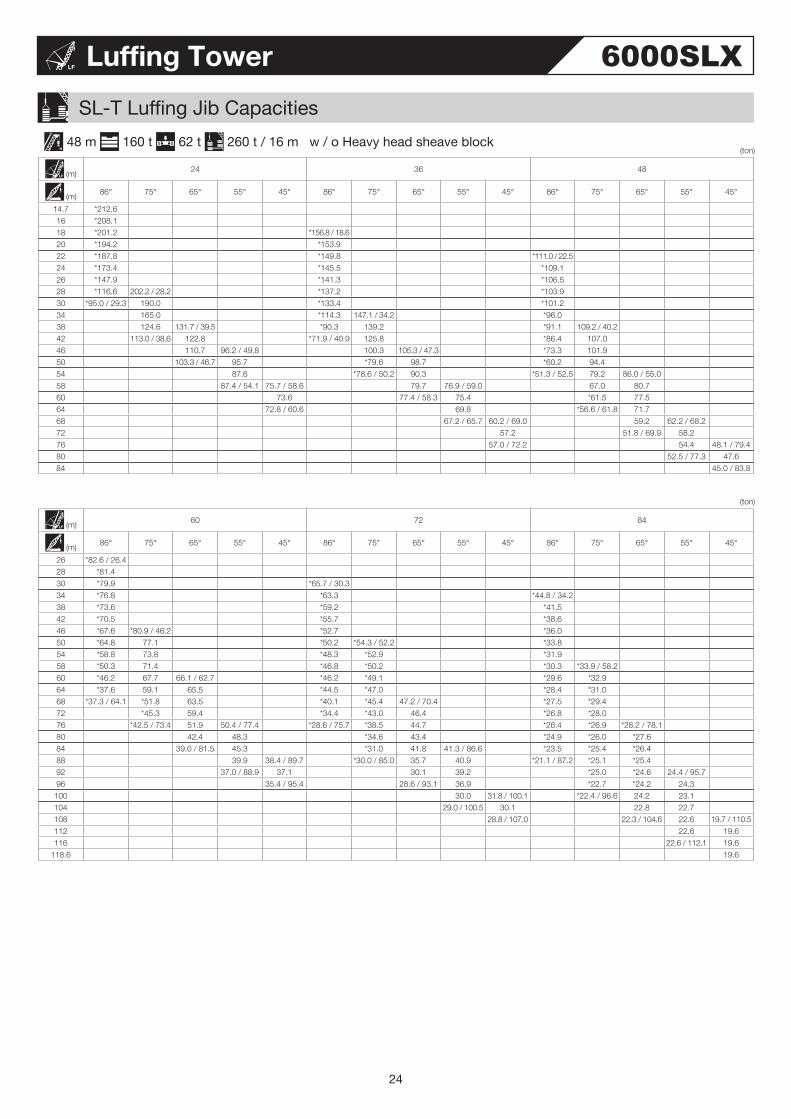
(ton) 36 m 160 t 62 t 260 t / 16 m w / o Heavy head sheave block
SL-T Luffing Jib Capacities
(m) 24 36 48
(m) 86° 75° 65° 55° 45° 86° 75° 65° 55° 45° 86° 75° 65° 55° 45°
13.9 *250.0 14 *250.0 16 *250.0 *210.0 / 17.818 *250.0 *209.4 20 *230.8 *204.0 *145.8 / 21.722 *198.3 *194.4 *145.4 24 *162.5 237.6 / 25.0 *181.5 *142.3 26 *130.2 227.3 *168.3 *137.4 28 *99.7 209.1 *149.6 *131.8 30 *91.0 / 28.5 193.5 *133.2 183.8 / 31.0 *125.9 34 135.8 159.1 / 34.5 *106.1 165.5 *113.5 134.2 / 37.038 *109.0 / 35.5 142.7 *82.7 134.1 *98.8 130.2 42 120.5 / 41.6 120.7 / 42.9 *68.9/40.0 108.2 123.9 / 42.2 *82.8 115.8 46 111.5 *85.1 112.2 *69.1 100.4 100.6 / 49.950 108.3 / 47.2 97.9 / 50.1 *77.9 / 47.1 102.0 93.8 / 52.1 *56.0 85.1 100.3 54 93.7 / 52.1 80.6 / 53.2 90.0 *50.2 / 51.6 *71.7 91.7 58 83.0 *58.6 83.0 60 81.7 / 58.8 76.0 / 60.5 *56.0 / 58.7 76.6 75.8 / 61.364 71.7 / 63.7 61.7 72.0 68 58.0 / 64.8 66.9 60.9 / 70.972 61.3 / 70.4 59.8 76 56.7 / 75.3
Luffing Tower
(ton)
(m) 60 72 84
(m) 86° 75° 65° 55° 45° 86° 75° 65° 55° 45° 86° 75° 65° 55° 45°
24 *102.6 / 25.626 *102.3 28 *99.6 *74.2 / 29.5
30 *96.6 *73.5 *49.7 / 33.4
34 *91.4 *68.6 *49.5 38 *87.1 *65.3 *47.5 42 *83.8 *88.7 / 43.0 *61.7 *44.3 46 *76.0 *85.6 *58.8 *61.0 / 49.0 *41.5 50 *65.5 82.3 *56.3 *60.2 *39.2 54 *56.4 78.3 76.9 / 57.6 *54.4 *57.2 *37.2 *40.1 / 55.058 *48.0 68.1 76.6 *52.6 *54.6 *35.5 *38.4 60 *43.9 63.6 75.4 *50.0 *53.5 *34.8 *37.3 64 *36.8 / 63.2 *55.1 72.2 *43.7 *51.8 *50.6 / 65.3 *33.4 *35.5 68 *46.9 63.3 61.7 / 70.5 *37.9 *49.7 49.4 *31.3 *33.9 72 *41.8 / 70.3 55.2 60.1 *32.2 *44.2 47.9 *29.4 *32.6 *34.1 / 73.076 45.8 56.2 *27.8 / 74.8 *39.4 46.8 44.4 / 79.7 *27.8 *31.0 *32.9 80 44.6 / 76.4 52.7 49.1 / 81.3 *34.9 46.5 44.3 *26.4 *29.2 *31.7 84 47.1 *31.9 / 81.9 40.7 43.6 *23.2 *27.6 *30.2 88 45.2 / 86.9 33.7 43.4 38.8 / 91.7 *20.4 / 86.4 *26.3 *28.5 *26.9 / 88.992 38.7 38.8 *23.9 *27.1 *26.3 96 34.3 / 93.6 38.1 *23.0 / 93.5 *25.9 25.9
100 36.8 / 98.5 *25.1 / 99.6 25.8 22.5/102.0104 25.5 22.5 108 25.3 / 105.2 22.5
110.1 22.5
23
(ton) 48 m 160 t 62 t 260 t / 16 m w / o Heavy head sheave block
SL-T Luffing Jib Capacities
Luffing Tower 6000SLX
(ton)
(m) 24 36 48
(m) 86° 75° 65° 55° 45° 86° 75° 65° 55° 45° 86° 75° 65° 55° 45°
14.7 *212.6 16 *208.1 18 *201.2 *156.8 / 18.620 *194.2 *153.9 22 *187.8 *149.8 *111.0 / 22.524 *173.4 *145.5 *109.1 26 *147.9 *141.3 *106.5 28 *116.6 202.2 / 28.2 *137.2 *103.9 30 *95.0 / 29.3 190.0 *133.4 *101.2 34 165.0 *114.3 147.1 / 34.2 *96.0 38 124.6 131.7 / 39.5 *90.3 139.2 *91.1 109.2 / 40.242 113.0 / 38.6 122.8 *71.9 / 40.9 125.8 *86.4 107.0 46 110.7 96.2 / 49.8 100.3 105.3 / 47.3 *73.3 101.9 50 103.3 / 46.7 95.7 *79.6 98.7 *60.2 94.4 54 87.6 *78.6 / 50.2 90.3 *51.3 / 52.5 79.2 86.0 / 55.058 87.4 / 54.1 75.7 / 58.6 79.7 76.9 / 59.0 67.0 80.7 60 73.6 77.4 / 58.3 75.4 *61.5 77.5 64 72.8 / 60.6 69.8 *56.6 / 61.8 71.7 68 67.2 / 65.7 60.2 / 69.0 59.2 62.2 / 68.272 57.2 51.8 / 69.9 58.2 76 57.0 / 72.2 54.4 48.1 / 79.480 52.5 / 77.3 47.6 84 45.0 / 83.8
(m) 60 72 84
(m) 86° 75° 65° 55° 45° 86° 75° 65° 55° 45° 86° 75° 65° 55° 45°
26 *82.6 / 26.428 *81.4 30 *79.9 *65.7 / 30.3
34 *76.8 *63.3 *44.8 / 34.2
38 *73.6 *59.2 *41.5 42 *70.5 *55.7 *38.6 46 *67.6 *80.9 / 46.2 *52.7 *36.0 50 *64.8 77.1 *50.2 *54.3 / 52.2 *33.8 54 *58.8 73.8 *48.3 *52.9 *31.9 58 *50.3 71.4 *46.8 *50.2 *30.3 *33.9 / 58.260 *46.2 67.7 66.1 / 62.7 *46.2 *49.1 *29.6 *32.9 64 *37.6 59.1 65.5 *44.5 *47.0 *28.4 *31.0 68 *37.3 / 64.1 *51.8 63.5 *40.1 *45.4 47.2 / 70.4 *27.5 *29.4 72 *45.3 59.4 *34.4 *43.0 46.4 *26.8 *28.0 76 *42.5 / 73.4 51.9 50.4 / 77.4 *28.6 / 75.7 *38.5 44.7 *26.4 *26.9 *28.2 / 78.180 42.4 48.3 *34.6 43.4 *24.9 *26.0 *27.6 84 39.0 / 81.5 45.3 *31.0 41.8 41.3 / 86.6 *23.5 *25.4 *26.4 88 39.9 38.4 / 89.7 *30.0 / 85.0 35.7 40.9 *21.1 / 87.2 *25.1 *25.4 92 37.0 / 88.9 37.1 30.1 39.2 *25.0 *24.6 24.4 / 95.796 35.4 / 95.4 28.6 / 93.1 36.9 *22.7 *24.2 24.3
100 30.0 31.8 / 100.1 *22.4 / 96.6 24.2 23.1 104 29.0 / 100.5 30.1 22.8 22.7 108 28.8 / 107.0 22.3 / 104.6 22.6 19.7 / 110.5112 22.6 19.6 116 22.6 / 112.1 19.6
118.6 19.6
24

Luffing Tower
SL-T Luffing Jib Capacities
60 m 160 t 62 t 260 t / 16 m w / o Heavy head sheave block
(m) 24 36 48
(m) 86° 75° 65° 55° 45° 86° 75° 65° 55° 45° 86° 75° 65° 55° 45°
15.5 *153.7 16 *152.6 18 *148.1 *116.2 / 19.520 *143.2 *115.5 22 *138.7 *112.4 *85.8 / 23.424 *134.7 *109.3 *85.2 26 *122.0 *106.1 *83.1 28 *110.7 *103.1 *81.1 30 *100.2 144.9 / 31.3 *100.2 *79.0 34 *98.3 / 30.1 138.8 *86.6 *108.8 / 37.3 *74.8 38 *108.4 *75.4 107.8 *70.9 42 *80.9 / 41.7 110.0 / 44.6 *66.9 / 41.7 101.8 *67.4 *81.5 / 43.346 106.1 *85.0 *62.6 *78.9 50 93.7 *68.7 89.2 / 52.3 *56.7 *74.8 54 75.6 / 51.8 77.4 / 56.7 *57.1 / 53.3 85.9 *51.8 / 53.3 70.6 58 75.4 78.9 *59.8 60 72.4 68.4 *55.2 72.9 64 64.9 / 61.0 58.7 / 67.1 51.9 / 63.4 62.3 / 65.9 *47.0 67.3 68 57.7 60.0 *45.1 / 64.9 62.4 72 56.6 / 69.1 49.9 49.7 50.1 / 75.176 46.2 / 72.6 46.8 / 77.4 41.4 / 74.9 49.3 80 44.9 46.2 84 44.4 / 80.7 37.0 36.8 / 87.888 36.2 / 84.2 36.7
92.3 34.4
(ton)
(m) 60 72 84
(m) 86° 75° 65° 55° 45° 86° 75° 65° 55° 45° 86° 75° 65° 55° 45°
26 *66.6 / 27.328 *66.1 30 *64.7 *52.5 / 31.2
34 *61.9 *51.2 *38.2 / 35.1
38 *59.1 *49.3 *37.3 42 *56.4 *47.4 *35.8 46 *53.8 *64.4 / 49.3 *45.1 *33.2 50 *50.2 *64.0 *42.8 *31.0 54 *46.0 *61.4 *40.9 *46.8 / 55.3 *29.2 58 *42.5 *58.5 *39.4 *44.9 *27.5 60 *40.9 *54.5 *38.8 *43.7 *26.8 *30.8 / 61.364 *38.0 *47.5 59.4 / 67.8 *36.2 *41.5 *25.6 *29.4 68 *37.4 / 64.9 *41.7 59.2 *34.0 *39.7 *24.6 *27.7 72 *36.7 54.9 *32.0 *38.3 40.8 / 75.5 *23.8 *26.1 76 *32.2 46.1 *29.9 *35.6 40.5 *23.4 *24.8 80 *31.6 / 76.5 38.5 *29.0 / 76.5 *32.1 38.8 *23.3 *23.7 *25.3 / 83.284 *32.0 42.2 / 84.2 *28.9 37.5 *22.6 *22.9 *25.1 88 *28.1 / 86.5 39.7 *25.9 33.7 *21.6 *22.3 *23.8 92 37.1 *25.9 / 88.1 29.1 33.5 / 93.4 *21.6 / 88.1 *22.0 *22.8 96 28.4 / 95.8 30.3 / 98.2 24.9 32.9 *20.3 *21.9
100 29.5 *22.8 / 98.1 30.9 *18.6 / 99.7 21.4 20.1 / 102.6104 27.9 / 103.9 29.1 21.2 19.8 108 24.0 / 107.3 23.7 / 108.6 20.0 19.2 112 22.5 18.9 / 109.7 18.8 116 21.4 / 115.5 18.7 17.6 / 119.0120 18.3 / 118.9 17.5 124 16.8
127.1 15.9
(ton)
25

(ton) 72 m 160 t 62 t 260 t / 16 m w / o Heavy head sheave block
SL-T Luffing Jib Capacities
Luffing Tower 6000SLX
(ton)
(m) 36 48 60
(m) 86° 75° 65° 55° 45° 86° 75° 65° 55° 45° 86° 75° 65° 55° 45°
20.3 *83.8 22 *82.0 24 *79.9 *67.1 / 24.226 *77.5 *65.7 28 *75.3 *64.2 *50.1 / 28.130 *73.2 *62.6 *49.1 34 *63.7 *59.4 *47.0 38 *55.5 *79.6 / 40.4 *56.5 *44.8 42 *48.9 *78.0 *50.9 *42.7 46 *47.9 / 42.6 *73.1 *45.8 *62.7 / 46.4 *40.5 50 *59.8 *41.5 *60.4 *36.9 *47.5 / 52.454 *49.0 72.4 / 57.4 *37.7 *57.3 *33.9 *46.7 58 *43.0 / 56.4 71.9 *37.7 / 54.1 *49.3 *31.3 *44.8 60 69.8 *45.6 *30.2 *43.8 64 54.8 *39.2 55.8 / 65.1 *28.0 *39.0 68 *41.3 *33.4 50.0 *27.2 / 65.7 *34.4 72 *39.9 / 68.4 51.2 / 72.7 41.6 *30.5 44.0 / 72.876 48.4 *33.9 *27.0 39.9 80 37.3 / 79.5 *27.0 41.5 / 81.9 *24.1 / 79.6 34.6 84 36.4 / 85.9 40.1 29.5 88 35.2 37.4 *25.0 33.8 / 91.192 34.5 / 89.2 29.6 / 91.0 *21.1 / 91.6 33.3 96 28.6 / 96.3 31.3
100 27.0 25.7 104 26.7 / 100.8 21.7 / 102.6 22.3 / 106.7108 21.9
112.4 20.4
(m) 72 84
(m) 86° 75° 65° 55° 45° 86° 75° 65° 55° 45°
32 *40.4 34 *39.6 *29.6 / 35.938 *38.2 *29.1
42 *36.6 *28.1
46 *35.1 *27.1 50 *33.7 *26.0 54 *32.3 *24.3 58 *31.1 *37.7 / 58.4 *22.8 60 *30.5 *36.7 *22.1 64 *29.5 *34.5 *21.0 *26.2 / 64.468 *27.7 *32.7 *20.0 *24.6 72 *26.1 *31.1 *19.3 *23.1 76 *24.7 *29.9 *18.8 *21.7 80 *24.2 / 77.3 *27.6 32.6 / 80.5 *18.6 *20.6 84 *25.0 31.3 *17.8 *19.7 88 *22.7 29.0 *17.1 *18.9 *20.4 / 88.392 *20.9 / 91.2 25.6 *16.9 / 88.9 *18.5 *19.4 96 22.5 *17.3 *18.4 100 *19.6 27.0 / 100.3 *16.0 *17.6 104 *17.4 / 103.2 25.4 *15.0 / 102.8 17.1 108 23.9 16.8 15.7 / 109.5112 20.3 15.6 15.3 116 18.1 / 114.2 16.7 / 117.1 14.3 / 114.8 14.8 120 15.9 14.5 124 14.9 14.4 11.7 / 127.5128 14.4 / 125.8 11.6 132 10.7
135.5 10.0
26

Luffing Tower
SL-T Luffing Jib Capacities
84 m 160 t 62 t 260 t / 16 m w / o Heavy head sheave block
(m) 48 60
(m) 86° 75° 65° 55° 45° 86° 75° 65° 55° 45°
25 *48.6 26 *48.1 28 *47.0 *37.2 / 28.930 *46.0 *36.8 34 *43.5 *35.3 38 *41.3 *33.6 42 *37.4 *32.0 46 *33.7 *45.0 / 49.5 *30.5 50 *30.6 *44.8 *28.8 54 *28.0 *42.9 *26.6 *34.5 / 55.558 *27.3 / 55.0 *38.0 *24.6 *33.7 60 *35.5 *23.7 *33.0 64 *30.9 *22.1 *30.4 68 *26.8 37.8 / 70.2 *21.2 / 66.6 *27.2 72 *23.9 / 71.1 35.9 *24.4 76 *31.2 *21.8 30.8 / 77.980 *26.4 *19.6 29.3 84 *21.8 *18.1 / 82.7 26.3 88 *20.5 / 85.1 31.7 / 88.8 *23.1 92 28.4 *20.1 96 23.1 *17.1 25.8/98.0100 20.3 / 97.9 *16.6 / 96.7 24.5 104 20.3 / 104.8 21.4 108 19.3 17.9 112 18.9 / 109.3 16.4 / 109.5 15.1 / 115.2116 14.9 120 13.9
120.9 13.7
(ton)
(m) 72 84
(m) 86° 75° 65° 55° 45° 86° 75° 65° 55°
32 *30.3 / 32.834 *30.0 *25.3 / 36.838 *28.8 *25.0 42 *27.6 *24.1 46 *26.4 *23.2 50 *25.2 *22.3 54 *23.4 *21.4 58 *21.8 *27.9 / 61.5 *20.4 60 *21.1 *27.9 / 61.5 *19.8 64 *19.8 *27.2 *18.6 *22.1 / 67.568 *18.6 *25.9 *17.7 *21.9 72 *17.5 *23.7 *16.9 *20.4 76 *16.6 *21.7 *16.3 *19.0 80 *16.1 / 78.2 *19.8 *15.6 *17.8 84 *18.2 25.5 / 85.6 *14.9 *16.8 88 *16.7 24.3 *14.3 *16.0 92 *15.2 22.3 *14.0 / 89.8 *15.3 17.2 / 93.396 *14.4 / 94.3 20.2 *14.9 16.4 100 18.2 *14.0 15.5 104 16.2 20.4 / 107.2 *13.0 14.7 108 *14.2 20.1 *12.5 / 105.9 14.1 112 *14.1 / 108.3 18.8 13.7 116 16.9 13.5 15.1 / 116.4120 14.5 12.4 / 119.9 14.2 124 13.8 / 121.1 10.4 / 125.6 13.2 128 9.9 12.2 132 9.1 11.3 134 9.0 / 132.4 11.1 / 132.7
(ton)
27

Notes
Luffing Tower 6000SLX
* ; With auxiliary weights / Without auxiliary weights
28
1. Capacities included in these charts are the maximum allowable, and are based on machine standing level on firm supporting surface under ideal job conditions.
2. Capacities are in metric tons, and are rated in accordance with European EN13 000 Standards in terms of machine stability and structural strength limitations.; each rated load capacity is based on machine's structural strength limitatiions.
3. Capacities are based on freely suspended loads and make no allowance for such factors as the effect of wind, sudden stopping of loads, supporting surface conditions, and operating speeds. Operator must reduce load ratings to take such conditions into account. Deduction from rated capacities must be made for weight of hook block, weighted ball/hook, sling, spreader bar, or other suspended gear.
4. The maximum rated load of the auxiliary sheave is the value remaining after the 1.3 ton mass of the auxiliary sheave and the mass of the “luffing jib hook” attached to the “luffing jib” are deducted from the maximum rated load of the “Luffing Jib Capacities.”
However, the maximum rated load of the auxiliary sheave is limited to 30 tons. The operating range of the auxiliary sheave is the range that has the maximum rated load of the luffing jib hook.
5. If the auxiliary sheave is attached, the maximum rated load of the “luffing jib hook” is the value remaining after the 1.3 ton mass of the auxiliary sheave and the mass of the auxiliary hook attached to the auxiliary sheave are deducted from the maximum rated load of the “Luffing Jib Capacities.”
6. If the heavy head sheave block is attached, the maximum rated load of the “luffing jib hook” is the value remaining after the 3.0 ton mass of he heavy head sheave block and the mass of the “luffing boom hook” attached to the heavy head sheave block are deducted from the “Luffing jib Maximum Rated Load” value.
7. The "working radius" is the horizontal distance from the slewing center to the center of gravity of a lifted load 8. Luffing Boom and Luffing Jib tilt angle ranges are according to the working range diagram. 9. The chart below shows the number of reeled lines and the maximum rated loads. (When the wire rope length is 800 m. )
10. The chart below shows the operable windings based on the length of each boom.
Hook Capacity (ton)Hook Weight (ton) 11 X 2Falls 10 X 2Falls 9 X 2Falls 8 X 2Falls 7 X 2Falls 6 X 2Falls 5 X 2Falls
320 Double-Reeling 7.9 - - 250 235 208 180 151
11 Falls 10 Falls 9 Falls 8 Falls 7 Falls 6 Falls 5 Falls 4 Falls 3 Falls 2 Falls 1 Fall
280 Single-Reeling 7.0 157 144 131 118 104 - - - - - -
160 Single-Reeling 3.9 157 144 131 118 104 90 76 - - - -
65 Single-Reeling * 3.0 / 2.0 - - - - - - 65 61 46 31 -
15 Single-Reeling 1.0 - - - - - - - - - - -
Tower Length (m) 36Hook Capacity (ton) / Jib Length (m)
24 30 36 42 48 54 60 66 72 78 84
320Double-Reeling
Max. 9 x 2 9 x 2 8 x 2 6 x 2 5 x 2 - - - - - -Min. 5 x 2 5 x 2 - - - - - - - - -
280Single-Reeling
Max. 11 11 10 9 8 8 7 6 - - -Min. 6 6 6 6 6 6 6 6 - - -
160Single-Reeling
Max. 11 11 10 9 8 8 7 6 5 - -Min. 5 5 5 5 5 5 5 5 5 - -
65Single-Reeling
Max. 5 5 5 5 5 5 5 5 5 4 4Min. 2 2 2 2 2 2 2 2 2 2 2
15Single-Reeling
- - - - - - - - - - -
Tower Length (m) 48Hook Capacity (ton) / Jib Length (m)
24 30 36 42 48 54 60 66 72 78 84
320Double-Reeling
Max. 8 x 2 7 x 2 6 x 2 5 x 2 5 x 2 5 x 2 - - - - -Min. 5 x 2 5 x 2 5 x 2 5 x 2 5 x 2 5 x 2 - - - - -
280Single-Reeling
Max. 10 9 8 8 7 6 6 - - - -Min. 6 6 6 6 6 6 6 - - - -
160Single-Reeling
Max. 10 9 8 8 7 7 6 5 5 - -Min. 5 5 5 5 5 5 5 5 5 - -
65Single-Reeling
Max. 5 5 5 5 5 5 5 5 5 4 3Min. 2 2 2 2 2 2 2 2 2 2 2
15Single-Reeling
- - - - - - - - - - -

Notes
Luffing Tower
29
11.If the total mass of the hook mass and the mass of all rigging components is lighter than the mass indicated on this chart, the hook may not lower even when a lowering operation is performed.
Please select a hook that can be lowered based on the boom length and number of windings.
Tower Length + Luffing Jib Length
1 Fall 2 Falls 3 Falls 4 Falls 5 Falls 6 Falls 7 Falls 8 Falls 9 Falls 10 Falls 11 Falls
60 m - 2.0 2.0 2.0 2.0 3.9 3.9 3.9 3.9 3.9 4.166 m - 2.0 2.0 2.0 2.0 3.9 3.9 3.9 3.9 4.0 4.572 m - 2.0 2.0 2.0 2.1 3.9 3.9 3.9 3.9 4.4 -78 m - 2.0 2.0 2.0 2.3 3.9 3.9 3.9 4.2 - -84 m - 2.0 2.0 2.0 2.4 3.9 3.9 4.0 - - -90 m - 2.0 2.0 2.1 2.6 3.9 3.9 4.3 - - -96 m - 2.0 2.0 2.2 2.8 3.9 4.0 - - - -102 m - 2.0 2.0 2.3 3.0 3.9 4.2 - - - -108 m - 2.0 2.0 2.5 3.1 3.9 - - - - -114 m - 2.0 2.0 2.6 3.3 - - - - - -120 m - 2.0 2.0 2.8 3.5 - - - - - -126 m - 2.0 2.1 2.9 - - - - - - -132 m - 2.0 2.3 3.0 - - - - - - -138 m - 2.0 2.4 - - - - - - - -144 m - 2.0 2.5 - - - - - - - -150 m - 2.0 2.6 - - - - - - - -156 m - 2.0 2.7 - - - - - - - -162 m - 2.0 - - - - - - - - -168 m - 2.0 - - - - - - - - -
Tower Length (m) 60Hook Capacity (ton) / Jib Length (m)
24 30 36 42 48 54 60 66 72 78 84
320Double-Reeling
Max. 6 x 2 5 x 2 5 x 2 - - - - - - - -Min. 5 x 2 5 x 2 5 x 2 - - - - - - - -
280Single-Reeling
Max. 8 8 7 7 6 - - - - - -Min. 6 6 6 6 6 - - - - - -
160Single-Reeling
Max. 8 8 7 6 6 5 5 - - - -Min. 5 5 5 5 5 5 5 - - - -
65Single-Reeling
Max. 5 5 5 5 5 5 5 4 4 3 3Min. 2 2 2 2 2 2 2 2 2 2 2
15Single-Reeling
- - - - - - - - - - -
Tower Length (m) 72Hook Capacity (ton) / Jib Length (m)
36 42 48 54 60 66 72 78 84
280Single-Reeling
Max. 6 - - - - - - - -Min. 6 - - - - - - - -
160Single-Reeling
Max. 6 5 5 - - - - - -Min. 5 5 5 - - - - - -
65Single-Reeling
Max. 5 5 5 4 4 3 3 3 2Min. 2 2 2 2 2 2 2 2 2
15Single-Reeling
- - - - - - - - -
Tower Length (m) 84Hook Capacity (ton) / Jib Length (m)
48 54 60 66 72 78 84
65Single-Reeling
Max. 4 3 3 3 2 2 2Min. 2 2 2 2 2 2 2
15Single-Reeling
- - - - - - -
12.Travel and slew with pallet grounded is not to be able to done. The pallet remains on the ground even if the rated load capacity is hoisted under the value with * mark.

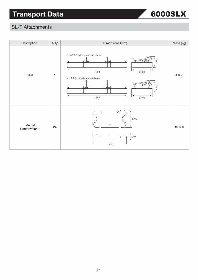
Transport Data 6000SLXSL-T Attachments
Description Q'ty Dimensions (mm) Mass (kg)
MB 10Long Mast
Base SectionWith W5 winch
With Bail / Bridle AssyWith Mast pendants
1
10 350 2 920
2 84
0
17 100
MB 10Long MastExtension
With Connecting PinWith Mast pendants
1
2 92010 360
2 28
0
4 500
MT 9Long MastTop Section
With Connecting PinWith Mast pendants
1
2 9809 720
2 84
0 8 300
Connector Beam 1
7 320
1 69
02
760
7 000
30
Transport Data 6000SLXSL-T Attachments
Description Q'ty Dimensions (mm) Mass (kg)
Pallet 1
7 500
7 500
w / o T.T.B quick disconnect device
w / T.T.B quick disconnect device
2 490
1 54
01
300
2 490
4 600
ExternalConterweight 24
2 000
300
3 880
10 000
31

(supersedes 0409 K 01T.EA041)
Printed in Japan
9-3, Higashi-Ueno 6-chome, Taito-ku, Tokyo 110-0015, JapanPhone: 81-3-3845-1387 Facsimile: 81-3-3845-1394http://www.hsc-cranes.com
• We are constantly improving our products and therefore reserve the right to change designs and speafications without notice. • Units in this specification are shown under International System of Units; the figures in parenthesis are under Gravitational System of Units as old one.


![En vitrine et au travers [Julie Bernier]TOPOS INTER, ART ACTUEL 122˙˙˙77 Boom Boom Boom Boom Boom! Une Honda Civic noire. Des mags verts et des néons bleus en d’sous du char](https://img.pdfslide.tips/doc/110x75/607c6f098fbce23952665715/en-vitrine-et-au-travers-julie-bernier-topos-inter-art-actuel-12277-boom.jpg)