Embed Size (px)
Citation preview

•Full power latching boom with quick reeveboom head
• 38-140 ft (11.6-42.7 m) five section, full power latching boom with quick reeve
boom head• Boom wear pads have Teflon pucks that
lubricate the boom sections (no grease)• Three boom extend modes. •No charted capacity reductions for
telescoping loads.• 35-58 ft (10.7-17.7 m) two piece,
on-board lattice fly with 2°, 15°, 30°,and 45° offsets
• One 16 ft (4.9 m) lattice insertplus 58 ft (17.7 m) two-pieceoffsettable fly option
• Two 16 ft (4.9 m) lattice insertsplus 58 ft (17.7 m) two-pieceoffsettable fly option
• No deducts for stowedattachments
• 238 ft (72.5 m) maximum tip height
• 16,880 lbs (7 656.6 kg)maximum winch line pull
• 459 fpm (139.9 m/min)maximum winch line speed
• Next generation operator’s cabwith improved visibility andergonomics
• 225 hp (168kW) Caterpillarengine with 724 ft-lbs (981J)of torque
• Spicer 6-speed power shifttransmission
• 4x2 and 4x4 drive with 29.5x25-28PR tires
• Four steering modes: independent front, combination,crab, and independent rear
• 4 link rear suspension withoptional hydro-gas suspension
• Modular counterweight design for multiple transport and lift scenarios
90-ton (80.0 mt)Rough Terrain Crane

Remarkable control, reliability and capacity performance• Caterpillar C6.6 electronic engine with 225 hp
(168 kW) provides 724 lb-ft (981 Nm) of torque• Electronic throttle for improved throttle response• Two automotive-style batteries linked in parallel
provide 700 cold cranking amps each for cold weather starting
• Rugged, lightweight steel pontoons• Hydraulic disc brakes for both service brakes and
parking brake• Metri-Pak wire harnesses have sealed relays and
connectors throughout for outstanding long-term reliability. All wires have flame retardant polyethyl-ene insulation, resulting in a higher heat resistant wiring system.
5-section full power latching boomwith attachment fl exibility• 38-140 ft (11.6-42.7 m) five-section boom
with three extend modes.• No charted capacity reductions for telescoping
loads.• Boom wear pads have Teflon pucks that lubricate
the boom sections (no grease)• Maximum tip height is 238 ft with the attachment
and main boom used in combination• Optional 35 ft (10.7 m) one-piece lattice fly and
optional 35 ft to 58 ft (10.7 m to 17.7 m) two-piece bi-fold lattice fly are offsettable to 2°, 15°, 30° and 45°.
• Optional 16 ft (4.9 m) lattice insert used alone or with 58 ft (17.7 m) two-piece offsettable fly
• Optional two 16 ft (4.9 m) lattice inserts plus 58 ft (17.7 m) two-piece offsettable fly
Operator cab features• Extra large
front window almost seamlessly merges into the roof window
• Sliding left side door, right and rear windows, and swing up top window provide excellent ventilation
• All gauges, switches, indicators, and controls are placed in the operator’s forward line of sight for excellent ergonomics
• All gauges and switches are backlit for excellent visibility when the cab working lights are switched to the on position
• Integral rated capacity limiter aids operator in safe and efficient operation by continuously monitoring boom length, boom angle, head height, radius of load, machine configuration, allowed load, and percent of allowed load.
• Available — Integrated air conditioning utilizes the same ventilation outlets as the standard heat-ing system
Powerful hydraulics• For greater productivity and control,
the five-pump hydraulic circuit allows simultaneous function of boom hoist, winch and swing.
• Piston motor hydraulic hoist system delivers superior hoisting. Matched sizes of main and auxiliary winches provide equal maximum available line pulls of 16,880 lbs (7 656.6 kg) and maximum line speeds of 459 fpm(140 m/min) on 16" (40.6 cm) root diameter drums.
Job site maneuverability• CALC — Outrigger beams have three differ-
ent stages (retracted, intermediate, and fully extended) providing lifting capacities in confined areas.
• Steering modes are chosen and performed with the steering wheel and include independent front steer, independent rear, four wheel steer, and "crab" steering.
Link-Belt Construction Equipment Company - Lexington, Kentuckywww.linkbelt.com
® Link-Belt is a registered trademark. Copyright 2006. All rights reserved.We reserve the right to change designs and specifications at any time.Litho in U.S.A. 10/06 474 #4328
90-ton (80.0 mt)Rough Terrain Crane

15479---0906---N4
RTC---8090 IILink-Belt Cranes
Technical DataSpecifications & Capacities
Telescopic Boom Rough Terrain Crane90 ton (80.0 metric ton)
CAUTION: This material is supplied forreference use only. Operator must refer toin---cab Crane RatingManual andOperator’sManual to determine allowable crane liftingcapacities and assembly and operatingprocedures.

5479---0906---N4
RTC---8090 II Link-Belt Cranes

5479---0906---N4
RTC---8090 IILink-Belt Cranes
Table Of ContentsBoom, Attachments, and Upper Structure 1. . . . . . . . . . . . . . . . . . . . . . . . . . . . . . . . . . . . . . . . . . . . . . . . . . . .Boom 1. . . . . . . . . . . . . . . . . . . . . . . . . . . . . . . . . . . . . . . . . . . . . . . . . . . . . . . . . . . . . . . . . . . . . . . . . . . . . . . . . . . .Boom Wear Pads 1. . . . . . . . . . . . . . . . . . . . . . . . . . . . . . . . . . . . . . . . . . . . . . . . . . . . . . . . . . . . . . . . . . . . . . . . .Boom Head 1. . . . . . . . . . . . . . . . . . . . . . . . . . . . . . . . . . . . . . . . . . . . . . . . . . . . . . . . . . . . . . . . . . . . . . . . . . . . .Boom Elevation 1. . . . . . . . . . . . . . . . . . . . . . . . . . . . . . . . . . . . . . . . . . . . . . . . . . . . . . . . . . . . . . . . . . . . . . . . . .Auxiliary Lifting Sheave --- Optional 1. . . . . . . . . . . . . . . . . . . . . . . . . . . . . . . . . . . . . . . . . . . . . . . . . . . . . . . . .Hook Blocks and Balls --- Optional 1. . . . . . . . . . . . . . . . . . . . . . . . . . . . . . . . . . . . . . . . . . . . . . . . . . . . . . . . . .Fly --- Optional 1. . . . . . . . . . . . . . . . . . . . . . . . . . . . . . . . . . . . . . . . . . . . . . . . . . . . . . . . . . . . . . . . . . . . . . . . . . .Fly Extensions --- Optional 1. . . . . . . . . . . . . . . . . . . . . . . . . . . . . . . . . . . . . . . . . . . . . . . . . . . . . . . . . . . . . . . . .Operator’s Cab and Controls 1. . . . . . . . . . . . . . . . . . . . . . . . . . . . . . . . . . . . . . . . . . . . . . . . . . . . . . . . . . . . . . . .Swing 2. . . . . . . . . . . . . . . . . . . . . . . . . . . . . . . . . . . . . . . . . . . . . . . . . . . . . . . . . . . . . . . . . . . . . . . . . . . . . . . . . . . .Electrical 2. . . . . . . . . . . . . . . . . . . . . . . . . . . . . . . . . . . . . . . . . . . . . . . . . . . . . . . . . . . . . . . . . . . . . . . . . . . . . . . . .Load Hoist System 3. . . . . . . . . . . . . . . . . . . . . . . . . . . . . . . . . . . . . . . . . . . . . . . . . . . . . . . . . . . . . . . . . . . . . . . . .Load Hoist Performance 3. . . . . . . . . . . . . . . . . . . . . . . . . . . . . . . . . . . . . . . . . . . . . . . . . . . . . . . . . . . . . . . . . . .2M Main and Optional Auxiliary Winches 3. . . . . . . . . . . . . . . . . . . . . . . . . . . . . . . . . . . . . . . . . . . . . . . . . . . .Hydraulic System 3. . . . . . . . . . . . . . . . . . . . . . . . . . . . . . . . . . . . . . . . . . . . . . . . . . . . . . . . . . . . . . . . . . . . . . . . . .Counterweight 3. . . . . . . . . . . . . . . . . . . . . . . . . . . . . . . . . . . . . . . . . . . . . . . . . . . . . . . . . . . . . . . . . . . . . . . . . . . .Carrier 4. . . . . . . . . . . . . . . . . . . . . . . . . . . . . . . . . . . . . . . . . . . . . . . . . . . . . . . . . . . . . . . . . . . . . . . . . . . . . . . . . . . .General 4. . . . . . . . . . . . . . . . . . . . . . . . . . . . . . . . . . . . . . . . . . . . . . . . . . . . . . . . . . . . . . . . . . . . . . . . . . . . . . . . . . .Outriggers 4. . . . . . . . . . . . . . . . . . . . . . . . . . . . . . . . . . . . . . . . . . . . . . . . . . . . . . . . . . . . . . . . . . . . . . . . . . . . . . . .Steering and Axles 4. . . . . . . . . . . . . . . . . . . . . . . . . . . . . . . . . . . . . . . . . . . . . . . . . . . . . . . . . . . . . . . . . . . . . . . . .Suspension 4. . . . . . . . . . . . . . . . . . . . . . . . . . . . . . . . . . . . . . . . . . . . . . . . . . . . . . . . . . . . . . . . . . . . . . . . . . . . . . .Tires and Wheels 4. . . . . . . . . . . . . . . . . . . . . . . . . . . . . . . . . . . . . . . . . . . . . . . . . . . . . . . . . . . . . . . . . . . . . . . . . .Brakes 4. . . . . . . . . . . . . . . . . . . . . . . . . . . . . . . . . . . . . . . . . . . . . . . . . . . . . . . . . . . . . . . . . . . . . . . . . . . . . . . . . . .Electrical 4. . . . . . . . . . . . . . . . . . . . . . . . . . . . . . . . . . . . . . . . . . . . . . . . . . . . . . . . . . . . . . . . . . . . . . . . . . . . . . . . .Engine 4. . . . . . . . . . . . . . . . . . . . . . . . . . . . . . . . . . . . . . . . . . . . . . . . . . . . . . . . . . . . . . . . . . . . . . . . . . . . . . . . . . .Transmission 4. . . . . . . . . . . . . . . . . . . . . . . . . . . . . . . . . . . . . . . . . . . . . . . . . . . . . . . . . . . . . . . . . . . . . . . . . . . . . .Carrier Speeds and Gradeability 5. . . . . . . . . . . . . . . . . . . . . . . . . . . . . . . . . . . . . . . . . . . . . . . . . . . . . . . . . . . . .Fuel Tank 5. . . . . . . . . . . . . . . . . . . . . . . . . . . . . . . . . . . . . . . . . . . . . . . . . . . . . . . . . . . . . . . . . . . . . . . . . . . . . . . . .Hydraulic System 5. . . . . . . . . . . . . . . . . . . . . . . . . . . . . . . . . . . . . . . . . . . . . . . . . . . . . . . . . . . . . . . . . . . . . . . . . .Pump Drive 5. . . . . . . . . . . . . . . . . . . . . . . . . . . . . . . . . . . . . . . . . . . . . . . . . . . . . . . . . . . . . . . . . . . . . . . . . . . . . . .Axle Loads 6. . . . . . . . . . . . . . . . . . . . . . . . . . . . . . . . . . . . . . . . . . . . . . . . . . . . . . . . . . . . . . . . . . . . . . . . . . . . . . . .General Dimensions 7. . . . . . . . . . . . . . . . . . . . . . . . . . . . . . . . . . . . . . . . . . . . . . . . . . . . . . . . . . . . . . . . . . . . . . . .Working Range Diagram 8. . . . . . . . . . . . . . . . . . . . . . . . . . . . . . . . . . . . . . . . . . . . . . . . . . . . . . . . . . . . . . . . . . . .Boom Extend Modes 9. . . . . . . . . . . . . . . . . . . . . . . . . . . . . . . . . . . . . . . . . . . . . . . . . . . . . . . . . . . . . . . . . . . . . . .Main Boom Lift Capacity Charts -- Standard 10. . . . . . . . . . . . . . . . . . . . . . . . . . . . . . . . . . . . . . . . . . . . . . . . .19,200 lb Counterweight --- Fully Extended Outriggers --- 360˚ Rotation 10. . . . . . . . . . . . . . . . . . . . . . . . . . .19,200 lb Counterweight --- On Tires --- Stationary --- Boom Centered Over Front Between Tire Tracks 1119,200 lb Counterweight --- On Tires --- Pick & Carry (Creep) --- Boom Centered Over Front 12. . . . . . . . .19,200 lb Counterweight --- On Tires --- Stationary --- 360˚ Rotation 12. . . . . . . . . . . . . . . . . . . . . . . . . . . . . .28,800 lb Counterweight --- Fully Extended Outriggers --- 360˚ Rotation 13. . . . . . . . . . . . . . . . . . . . . . . . . . .

5479---0906---N4
RTC---8090 II Link-Belt Cranes
Fly Attachment Lift Capacity Charts -- Optional 14. . . . . . . . . . . . . . . . . . . . . . . . . . . . . . . . . . . . . . . . . . . . . . .19,200 lb Counterweight --- Fully Extended Outriggers --- 360˚ Rotation 14. . . . . . . . . . . . . . . . . . . . . . . . . . .140 ft Main Boom Length --- 2˚ Fly Offset 14. . . . . . . . . . . . . . . . . . . . . . . . . . . . . . . . . . . . . . . . . . . . . . . . . . . .140 ft Main Boom Length --- 15˚ Fly Offset 14. . . . . . . . . . . . . . . . . . . . . . . . . . . . . . . . . . . . . . . . . . . . . . . . . . .140 ft Main Boom Length --- 30˚ Fly Offset 15. . . . . . . . . . . . . . . . . . . . . . . . . . . . . . . . . . . . . . . . . . . . . . . . . . .140 ft Main Boom Length --- 45˚ Fly Offset 15. . . . . . . . . . . . . . . . . . . . . . . . . . . . . . . . . . . . . . . . . . . . . . . . . . .28,800 lb Counterweight --- Fully Extended Outriggers --- 360˚ Rotation 16. . . . . . . . . . . . . . . . . . . . . . . . . . .140 ft Main Boom Length --- 2˚ Fly Offset 16. . . . . . . . . . . . . . . . . . . . . . . . . . . . . . . . . . . . . . . . . . . . . . . . . . . .140 ft Main Boom Length --- 15˚ Fly Offset 16. . . . . . . . . . . . . . . . . . . . . . . . . . . . . . . . . . . . . . . . . . . . . . . . . . .140 ft Main Boom Length --- 30˚ Fly Offset 17. . . . . . . . . . . . . . . . . . . . . . . . . . . . . . . . . . . . . . . . . . . . . . . . . . .140 ft Main Boom Length --- 45˚ Fly Offset 17. . . . . . . . . . . . . . . . . . . . . . . . . . . . . . . . . . . . . . . . . . . . . . . . . . .
Main Boom Lift Capacity Charts -- Metric 18. . . . . . . . . . . . . . . . . . . . . . . . . . . . . . . . . . . . . . . . . . . . . . . . . . . .8 709kg Counterweight --- Fully Extended Outriggers --- 360˚ Rotation 18. . . . . . . . . . . . . . . . . . . . . . . . . . . .8 709kg Counterweight --- On Tires --- Stationary --- Boom Centered Over Front Between Tire Tracks 19.8 709kg Counterweight --- On Tires --- Pick & Carry (Creep) --- Boom Centered Over Front 20. . . . . . . . . .8 709kg Counterweight --- On Tires --- Stationary --- 360˚ Rotation 20. . . . . . . . . . . . . . . . . . . . . . . . . . . . . . .13 064kg Counterweight --- Fully Extended Outriggers --- 360˚ Rotation 21. . . . . . . . . . . . . . . . . . . . . . . . . .Fly Attachment Lift Capacity Charts -- Optional 22. . . . . . . . . . . . . . . . . . . . . . . . . . . . . . . . . . . . . . . . . . . . . . .8 709kg Counterweight --- Fully Extended Outriggers --- 360˚ Rotation 22. . . . . . . . . . . . . . . . . . . . . . . . . . . .42.67m Main Boom Length --- 2˚ Fly Offset 22. . . . . . . . . . . . . . . . . . . . . . . . . . . . . . . . . . . . . . . . . . . . . . . . . .42.67m Main Boom Length --- 15˚ Fly Offset 22. . . . . . . . . . . . . . . . . . . . . . . . . . . . . . . . . . . . . . . . . . . . . . . . .42.67m Main Boom Length --- 30˚ Fly Offset 23. . . . . . . . . . . . . . . . . . . . . . . . . . . . . . . . . . . . . . . . . . . . . . . . .42.67m Main Boom Length --- 45˚ Fly Offset 23. . . . . . . . . . . . . . . . . . . . . . . . . . . . . . . . . . . . . . . . . . . . . . . . .13 064kg Counterweight --- Fully Extended Outriggers --- 360˚ Rotation 24. . . . . . . . . . . . . . . . . . . . . . . . . .42.67m Main Boom Length --- 2˚ Fly Offset 24. . . . . . . . . . . . . . . . . . . . . . . . . . . . . . . . . . . . . . . . . . . . . . . . . .42.67m Main Boom Length --- 15˚ Fly Offset 24. . . . . . . . . . . . . . . . . . . . . . . . . . . . . . . . . . . . . . . . . . . . . . . . .42.67m Main Boom Length --- 30˚ Fly Offset 25. . . . . . . . . . . . . . . . . . . . . . . . . . . . . . . . . . . . . . . . . . . . . . . . .42.67m Main Boom Length --- 45˚ Fly Offset 25. . . . . . . . . . . . . . . . . . . . . . . . . . . . . . . . . . . . . . . . . . . . . . . . .
15479---0906---N4
RTC---8090 IILink-Belt Cranes
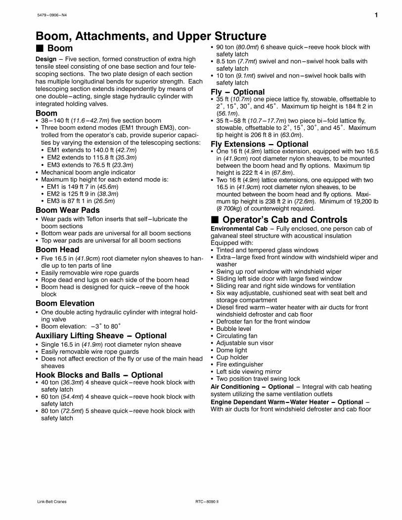
Boom, Attachments, and Upper StructureJ BoomDesign --- Five section, formed construction of extra hightensile steel consisting of one base section and four tele-scoping sections. The two plate design of each sectionhas multiple longitudinal bends for superior strength. Eachtelescoping section extends independently by means ofone double---acting, single stage hydraulic cylinder withintegrated holding valves.BoomS 38---140 ft (11.6 ---42.7m) five section boomS Three boom extend modes (EM1 through EM3), con-trolled from the operator’s cab, provide superior capaci-ties by varying the extension of the telescoping sections:S EM1 extends to 140.0 ft (42.7m)S EM2 extends to 115.8 ft (35.3m)S EM3 extends to 76.5 ft (23.3m)
S Mechanical boom angle indicatorS Maximum tip height for each extend mode is:S EM1 is 149 ft 7 in (45.6m)S EM2 is 125 ft 9 in (38.3m)S EM3 is 87 ft 1 in (26.5m)Boom Wear PadsS Wear pads with Teflon inserts that self ---lubricate theboom sections
S Bottom wear pads are universal for all boom sectionsS Top wear pads are universal for all boom sectionsBoom HeadS Five 16.5 in (41.9cm) root diameter nylon sheaves to han-dle up to ten parts of line
S Easily removable wire rope guardsS Rope dead end lugs on each side of the boom headS Boom head is designed for quick---reeve of the hookblockBoom ElevationS One double acting hydraulic cylinder with integral hold-ing valve
S Boom elevation: ---3˚ to 80˚Auxiliary Lifting Sheave --- OptionalS Single 16.5 in (41.9m) root diameter nylon sheaveS Easily removable wire rope guardsS Does not affect erection of the fly or use of the main headsheavesHook Blocks and Balls --- OptionalS 40 ton (36.3mt) 4 sheave quick---reeve hook block withsafety latch
S 60 ton (54.4mt) 4 sheave quick---reeve hook block withsafety latch
S 80 ton (72.5mt) 5 sheave quick---reeve hook block withsafety latch
S 90 ton (80.0mt) 6 sheave quick---reeve hook block withsafety latch
S 8.5 ton (7.7mt) swivel and non---swivel hook balls withsafety latch
S 10 ton (9.1mt) swivel and non---swivel hook balls withsafety latchFly --- OptionalS 35 ft (10.7m) one piece lattice fly, stowable, offsettable to2˚, 15˚, 30˚, and 45˚. Maximum tip height is 184 ft 2 in(56.1m).
S 35 ft---58 ft (10.7 ---17.7m) two piece bi---fold lattice fly,stowable, offsettable to 2˚, 15˚, 30˚, and 45˚. Maximumtip height is 206 ft 8 in (63.0m).Fly Extensions --- OptionalS One 16 ft (4.9m) lattice extension, equipped with two 16.5in (41.9cm) root diameter nylon sheaves, to be mountedbetween the boom head and fly options. Maximum tipheight is 222 ft 4 in (67.8m).
S Two 16 ft (4.9m) lattice extensions, one equipped with two16.5 in (41.9cm) root diameter nylon sheaves, to bemounted between the boom head and fly options. Maxi-mum tip height is 238 ft 2 in (72.6m). Minimum of 19,200 lb(8 700kg) of counterweight required.
J Operator’s Cab and ControlsEnvironmental Cab --- Fully enclosed, one person cab ofgalvaneal steel structure with acoustical insulationEquipped with:S Tinted and tempered glass windowsS Extra---large fixed front window with windshield wiper andwasher
S Swing up roof window with windshield wiperS Sliding left side door with large fixed windowS Sliding rear and right side windows for ventilationS Six way adjustable, cushioned seat with seat belt andstorage compartment
S Diesel fired warm---water heater with air ducts for frontwindshield defroster and cab floor
S Defroster fan for the front windowS Bubble levelS Circulating fanS Adjustable sun visorS Dome lightS Cup holderS Fire extinguisherS Left side viewing mirrorS Two position travel swing lockAir Conditioning --- Optional --- Integral with cab heatingsystem utilizing the same ventilation outletsEngine Dependant Warm---Water Heater --- Optional ---With air ducts for front windshield defroster and cab floor

2 5479---0906---N4
RTC---8090 II Link-Belt Cranes
Steering Column --- Pedestal type with tilt and telescopefunctions for operator comfort. Column includes the follow-ing controls and indicators:Left and right levers include:
S Horn buttonS Turn signal switchS Driving light switchS Transmission direction switchPanel mounted switches for:
S Travel park brakeS Steer mode selectorS 2/4 wheel drive/range selectorS Transmission gear selectorS Hazard flasherPanel mounted indicator/warning lights for:
S Transmission temperatureS Engine oil pressureS Travel park brakeS Service brakeS Turn signalsS Rear wheel offset---optionalS Emergency steer --- optionalArmrest Controls --- Two dual axis hydraulic joystick con-trollers or optional single axis hydraulic controllers for:S SwingS Boom hoistS Main rear winchS Auxiliary front winch --- optionalS Drum rotation indicationS Drum rotation indicator activation switchS Winch high/low speed and disable switch(es)S Warning horn buttonS Swing park brakeOutrigger Controls --- Hand held control box with umbilicalcord gives the operator the freedom to view operation whilesetting the outriggers.Foot ControlsS Boom telescopeS Swing brakeS Engine throttleS Service brakeRight Front Console --- Controls and indicators for:S Engine ignition S Console dimmer switchS Engine throttle lock S Bubble levelS Function disable S 12 volt power connectionS Front windshield wiper S Air conditioning --- optionaland washer S Boom floodlight --- optional
S Cab floodlights S Rotating beacon/StrobeS Warning horn light --- optionalS Heating controls S Third wrap indicator ---
optionalCab Instrumentation --- Ergonomically positioned, analoginstrumentation for crane operation including:S Engine coolant temperature with warning indicatorS Hydraulic oil temperature with warning indicatorS Fuel level with warning indicatorS TachometerS Transmission temperature with warning indicatorS Voltmeter with warning indicator
Rated Capacity Limiter --- Microguard graphic audio---visual warning system integrated into the dash with anti ---two block and function limiter. Operating data availableincludes:S Crane configurationS Boom length and angleS Boom head heightS Allowed load and % of allowed loadS Boom angleS Radius of loadS Actual loadS Operator settable alarms (include):S Maximum and minimum boom anglesS Maximum tip heightS Maximum boom lengthS Swing left/right positionsS Operator defined area (imaginary plane)
Integrated Third Wrap Indicator --- Optional --- Micro-guard color display visually and audibly warns the operatorwhen the wire rope is on the first/bottom layer and whenthe wire rope is down to the last three wraps.Internal RCL Light Bar --- Optional --- Visually informs theoperator when crane is approaching maximum load capac-ity with a series of green, yellow, and red lights.External RCL Light Bar --- Optional --- Visually informs theground crew when crane is approaching maximum loadcapacity with a series of green, yellow, and red lights.
J SwingMotor/Planetary --- Bi ---directional hydraulic swing motormounted to a planetary reducer for 360˚ continuoussmooth swing at 1.9 rpmSwing Park Brake --- 360˚, electric over hydraulic, (springapplied/hydraulic released) multi ---disc brake mounted onthe speed reducer. Operated by a switch from the opera-tor’s cab.Swing Brake --- 360˚, foot operated, hydraulic applied discbrake mounted to the speed reducerSwing Lock --- Two---position swing lock (boom over frontor rear) operated from the operator’s cab360˚ Positive Swing Lock --- Optional --- Meets New YorkCity requirement
J ElectricalSwing Alarm --- Audio warning device signals when theupper is swinging.LightsS Two working lights on front of the cabS One rotating amber beacon on top of the cab --- optionalS One amber strobe beacon on top of the cab --- optionalS Boom floodlight --- optional

35479---0906---N4
RTC---8090 IILink-Belt Cranes
J Load Hoist SystemLoad Hoist Performance
Main (Rear) and Auxiliary (Front) Winches --- 3/4 in (19mm) RopeMaximum Line Pull Normal Line Speed High Line Speed Layer Total
Layer lb kg ft/min m/min ft/min m/min ft m ft m1 16,880 7 656.6 172 52.4 341 104.0 114 34.7 114 34.72 15,519 7 039.3 187 57.0 371 113.1 124 37.8 238 72.53 14,362 6 514.5 202 61.6 401 122.2 134 40.8 372 113.44 13,365 6 062.3 217 66.1 430 131.1 144 43.9 516 157.35 12,497 5 668.5 232 70.7 460 140.2 154 46.9 670 204.26 --- --- --- --- --- --- --- --- --- --- --- --- --- --- --- --- --- --- 164 50.0 834 254.2
Wire Rope ApplicationDiameter
TypeMaximum
Permissible Load
in mm lb kg
Main (Rear) Winch
Standard 3/4 19 4 strand, low torque, right regular lay (Type GC) 22,400 10 160.5Optional 3/4 19 18x19 rotation resistant --- right regular lay (Type RB) 12,920 5 860.5Optional 3/4 19 36x7 rotation resistant --- right regular lay (Type ZB) 15,600 7 076.2
Auxiliary (Front)Winch
Standard 3/4 19 4 strand, low torque, right regular lay (Type GC) 22,400 10 160.5Optional 3/4 19 18x19 rotation resistant --- right regular lay (Type RB) 12,920 5 860.5Optional 3/4 19 36x7 rotation resistant --- right regular lay (Type ZB) 15,600 7 076.2
2M Main and Optional Auxiliary WinchesS Axial piston, full and half displacement (2---speed) motorsdriven through planetary reduction unit for positive con-trol under all load conditions.
S Grooved laggingS Power up/down mode of operationS Hoist drum cable follower --- optionalS Drum rotation indicatorS Drum diameter: 16 in (40.6cm)S Rope length:S Main: 730 ft (222.5m)S Auxiliary: 500 ft (152.4m) or 730 ft (222.5m)
S Maximum rope storage: 834 ft (254.2m)S Terminator style socket and wedgeThird wrap indicator --- optional --- Visually and audiblywarns the operator when the wire rope is on the first/bottomlayer and when the wire rope is down to the last threewraps
J Hydraulic SystemCounterbalance Valves --- All hoist motors, boom extendcylinders, and boom hoist cylinders are equipped withcounterbalance valves to provide load lowering and pre-vents accidental load drop when hydraulic power is sud-denly reduced.Hydraulic Oil Coolers --- Two carrier mounted coolers re-move heat from the hydraulic oil. One is integral to the en-gine radiator/charge air cooler and the other is mounted onleft side of the carrier.
J CounterweightStandard --- Total of 19,200 lb (8 709.0kg) counterweightconsisting of two counterweights pinned to the upper withcapacities for:S 0 lb (0kg) counterweight*S 9,600 lb (4 354.5kg) counterweightS 19,200 lb (8 709.0kg) counterweightOptional --- 9,600 lb (4 354.5kg) in addition to standardcounterweight for a total of 28,800 lb (13 063.0kg) coun-terweight with capacities for:S 0 lb (0kg) counterweight*S 9,600 lb (4 354.5kg) counterweightS 19,200 lb (8 709.0kg) counterweightS 28,800 lb (13 063.0kg) counterweight** Travel speed limited to 5 mph.Optional --- Hydraulic counterweight removal activatedby a hand---held controller with enough cable to accessthe pins on each side of the counterweights.

4 5479---0906---N4
RTC---8090 II Link-Belt Cranes
CarrierJ GeneralS 10 ft 9 in (3.28m) wideS 14 ft 4 in (4.37m) wheelbase (centerline of first axle tocenterline of second axle)Frame --- Box---type, torsion resistant, welded constructionmade of high tensile steel. Equipped with front and reartowing and tie---down lugs, tow connections, and accessladders.
J OutriggersBoxes --- Two double box, front and rear welded to carrierframeBeams and Jacks --- Four single stage beams with Con-fined Area Lifting Capacities (CALCt) provide selectableoutrigger extensions of full, intermediate, and retracted.Hydraulically controlled from the operator’s cab with inte-gral check valves.Pontoons --- Four lightweight, quick release, 23.5 x 23.5 in(59.7 x 59.7cm), steel pontoons with contact area of 460 in2(2 968cm2) can be stored for road travel in storage rackson the carrier.Main Jack Reaction --- 108,000 lb (48 988kg) force and235 psi (1 620kPa) ground bearing pressure
J Steering and AxlesSteering --- Four independent modes consisting of twowheel front, two wheel rear, four wheel, and crab. Eachmode is controlled from the steering wheel and is selectedby a switch in the operator’s cab.Drive --- Two modes: 4 x 2 and 4 x 4 for off highway travelAxle 1 --- Steered, non---driven for 4 x 2 and steered, drivenfor 4 x 4Axle 2 --- Steered, driven
J SuspensionFront --- Rigid mount to the carrier frameRear --- The rear axle is suspended on the oscillation cylin-ders with motion of the axle controlled by a four bar linkagesystem. The oscillation cylinders lockout when the upperstructure rotates 2.5˚ past centerline.S Hydro---gas rear suspension --- optionalRide Height Adjustment --- Suspension can be lowered fortransport using a hand---held controller from level ground.
J Tires and WheelsFront and Rear --- Four (single) 29.5 x 25---28 ply rating,earthmover type tires on steel disc wheelsS Spare tires and wheels --- optional
J BrakesService --- Full hydraulic, dual circuit, disc type brakes onall wheel endsParking/Emergency --- Spring applied type, acting on frontaxle
J ElectricalTwo batteries provide 12 volt starting and operationLightsS Front lighting includes two main headlights and two park-ing/directional indicators.
S Side lighting includes two parking/directional indicatorsper side.
S Rear lighting includes two parking/directional indicators,two parking/brake lights, and two reversing lights.
S Other equipment includes hazard/warning system, cablight, instrument panel light, and signal horn.
J EngineSpecification CAT C6.6
Numbers of Cylinders 6
Cycle 4
Bore and Stroke: inch (mm) 4.13 x 5.00 (105 x 127)
Piston Displacement: in3 (L) 403 (6.6)
Max. Brake Horsepower: hp (kW) 225 (167.8) @ 2,200 rpm
Peak Torque: ft lb (Nm) 727 (986) @ 1,400 rpm
Alternator: volts --- amps 12 --- 150
Crankcase Capacity: qt (L) 18.4 (17.4)
S Mechanically driven fan and thermostatically controlled radiator
J TransmissionPowershift --- Three speed with high/low range for 6 for-ward and 6 reverse gears. Front axle disconnect for two orfour wheel drive. Front axle disconnects in high range.
55479---0906---N4
RTC---8090 IILink-Belt Cranes
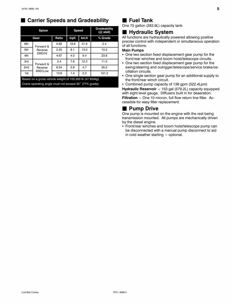
J Carrier Speeds and Gradeability
Spicer Speed Gradeability(@ stall)
Gear Ratio mph km/h % Grade
6thForward &Reverse2WD/Hi
0.82 19.8 31.9 2.4
5th 2.25 8.1 13.0 10.2
4th 4.67 4.0 6.4 23.8
3rdForward &Reverse4WD/Low
2.4 7.6 12.3 11.0
2nd 6.54 2.9 4.7 35.2
1st 13.6 1.4 2.3 101.2
Based on a gross vehicle weight of 105,500 lb (47 854kg).Crane operating angle must not exceed 35˚ (77% grade).
J Fuel TankOne 75 gallon (283.9L) capacity tank
J Hydraulic SystemAll functions are hydraulically powered allowing positiveprecise control with independent or simultaneous operationof all functions.Main PumpsS One two section fixed displacement gear pump for thefront/rear winches and boom hoist/telescope circuits.
S One two section fixed displacement gear pump for theswing/steering and outrigger/telescope/service brake/os-cillation circuits.
S One single section gear pump for an additional supply tothe front/rear winch circuit.
S Combined pump capacity of 138 gpm (522.4Lpm)Hydraulic Reservoir --- 153 gal (579.2L) capacity equippedwith sight level gauge. Diffusers built in for deaeration.Filtration --- One 10 micron, full flow return line filter. Ac-cessible for easy filter replacement.
J Pump DriveOne pump is mounted on the engine with the rest beingtransmission mounted. All pumps are mechanically drivenby the diesel engine.S Front/rear winches and boom hoist/telescope pump canbe disconnected with a manual pump disconnect to aidin cold weather starting --- optional.

6 5479---0906---N4
RTC---8090 II Link-Belt Cranes
Axle Loads
Base crane with zerocounterweight and full tank of fuel
Gross VehicleWeight (1)
Upper Facing Front Upper Facing RearFront Axles Rear Axles Front Axles Rear Axles
lb kg lb kg lb kg lb kg lb kg79,919 36 251 51,085 23 172 28,834 13 079 22,585 10 245 57,334 26 007
Pintle hook, front 13 6 17 8 ---5 ---2 17 8 ---5 ---2Pintle hook, rear 13 6 ---5 ---2 18 8 ---5 ---2 18 8Rear steer indicator 6 3 0 0 6 3 0 0 6 3Hydro---gas suspension 56 25 20 9 36 16 20 9 36 16Pump disconnect 39 18 7 3 32 15 7 3 32 15Operator in cab 250 113 140 64 110 50 110 50 140 64Hoist drum follower --- main 69 31 ---24 ---11 93 42 93 42 ---24 ---11Auxiliary winch with 500 ft (152.4m)wire rope 608 276 ---74 ---34 682 309 682 309 ---74 ---34
Hoist drum follower --- auxiliary 69 31 ---6 ---3 75 34 75 34 ---6 ---3Substitute 500 ft (152.4m) wire ropewith 730 ft (222.5m) --- auxiliary 288 131 ---9 ---4 297 135 297 135 ---9 ---4
Remove 730 ft (222.5m) wire ropefrom rear (main) winch ---931 ---422 203 92 ---1,134 ---514 ---1,134 ---514 203 92
Remove 500 ft (152.4m) wire ropefrom front (auxiliary) winch ---643 ---292 21 10 ---664 ---301 ---664 ---301 21 10
Counterweight removal 208 94 ---62 ---28 270 122 270 122 ---62 ---28One slab of counterweight on upper 9,600 4 355 ---3,356 ---1 522 12,956 5 877 12,956 5 877 ---3,356 ---1 522Two slabs of counterweight onupper 19,200 8 709 ---6,712 ---3 045 25,912 11 754 25,912 11 754 ---6,712 ---3 045
Three slabs of counterweight onupper 28,800 13 064 ---10,068 ---4 567 38,868 17 630 38,868 17 630 ---10,068 ---4 567
Emergency steering 255 116 39 18 216 100 216 100 39 18360˚ mechanical swing lock 140 64 72 33 68 31 68 31 72 33Air conditioning 179 81 50 23 129 59 129 59 50 23Floodlight to front of boom basesection 7 3 10 5 ---3 ---1 ---3 ---1 10 5
Fly mounting brackets to boom basesection for fly options 176 80 239 108 ---63 ---29 ---63 ---29 239 108
35 ft (10.67m) offsettable fly ---stowed 1,591 722 2,576 1 168 ---984 ---446 ---984 ---446 2,576 1 168
35---58 ft (10.67 ---17.68m) offsettablefly --- stowed 2,263 1 026 3,257 1 477 ---994 ---451 ---994 ---451 3,257 1 477
Auxiliary lifting sheave 110 50 304 138 ---194 ---88 ---194 ---88 304 13890 ton (80.0mt) 6---sheave hookblock at bumper 1,554 705 2,358 1 070 ---804 ---365 ---804 ---365 2,358 1 070
80 ton (72.5mt) 5---sheave hookblock at bumper 1,406 638 2,134 968 ---728 ---330 ---728 ---330 2,134 968
60 ton (54.4mt) 4---sheave hookblock at bumper 1,109 503 1,683 763 ---574 ---260 ---574 ---260 1,683 763
10 ton (9.1mt) hook ball at bumper 550 250 834 378 ---284 ---129 ---284 ---129 834 3788.5 ton (7.7mt) hook ball at bumper 360 163 546 248 ---186 ---84 ---186 ---84 546 24890 ton (80.0mt) 6---sheave hookblock at boom head 1,554 705 4,138 1 877 ---2,584 ---1 172 ---2,584 ---1 172 4,138 1 877
80 ton (72.5mt) 5---sheave hookblock at boom head 1,406 638 3,744 1 698 ---2,338 ---1 061 ---2,338 ---1 061 3,744 1 698
60 ton (54.4mt) 4---sheave hookblock at boom head 1,109 503 2,953 1 340 ---1,844 ---836 ---1,844 ---836 2,953 1 340
10 ton (9.1mt) hook ball at boomhead 550 250 1,465 665 ---915 ---415 ---915 ---415 1,465 665
8.5 ton (7.7mt) hook ball at boomhead 360 163 959 435 ---599 ---272 ---599 ---272 959 435
Tire Maximum Allowable Axle Load @ 20 mph (32.2km/h)
29.5 x 25 (28---PR) 55,000 lb (24 948kg)(1) Adjust gross vehicle weight and axle loading according to component weight.Note: All weights are ±3%.

75479---0906---N4
RTC---8090 IILink-Belt Cranes
General Dimensions
Not To Scale
C of RotationL
C of RotationL
Turning Radius --- Front Wheel (4x2) Steering English MetricWall to wall over carrier 48’ 3” 14.71mWall to wall over boom attachment 60’ 1” 18.32mCurb to curb 46’ 8” 13.80mCenterline of tire 45’ 4” 10.28m
Tail Swing English MetricWith counterweight 14’ 2” 4.32m
Turning Radius --- All Wheel (4x4) Steering English MetricWall to wall over carrier 27’ 10” 8.49mWall to wall over boom attachment 38’ 11” 11.86mCurb to curb 26’ 0” 7.91mCenterline of tire 24’ 7” 7.50m
38’ 0.25”(11.59m)
7’ 0”(2.13m)
12’ 5.5”(3.80m)
25˚28.4˚
7’ 2”(2.18m)
7’ 2”(2.18m)
11’ 9”(3.59m)
12’ 3”(3.73m)13’ 9.75”(4.21m)
13’ 3.75”(4.06m)
45’ 9.25”(13.94m)
6’ 3.25”(1.91m)
7’ 9.75”(2.39m)@ 0˚5’ 9.75”(1.77m)@ ---3˚
10’ 2.25”(3.11m)
13.50”(0.35m)
7.50”(0.19m)
25.75”(0.65m)
8’ 2.25”(2.49m)
9’ 6.75”(2.91m)
10’ 9”(3.28m)
17’ 9.25”(5.42m)
24’ 0”(7.32m)
16.75”(0.43m)
13’ 0”(3.96m)@ 0˚
10’ 11.75”(3.35m)@ ---3˚
Without counterweight 13’ 2” 3.97m
47’ 5.25”(14.46m)
2’ 8.25”(0.82m) 22.34”
(0.57m)
31.25”(0.79m)
5’ 6”(1.68m)

8 5479---0906---N4
RTC---8090 II Link-Belt Cranes
Working Range Diagram
2040
50
60
70
80
90
100
30110130
120
170
160
150
140
Operating Radius From Axis Of Rotation In Feet (Meters)
HeightInFeet(Meters)AboveGround
(6.1)(12.2)
(15.2)
(18.3)
(21.3)
(24.4)
(27.4)
(30.5)
(9.1)(33.5)(39.6)
(36.6)
(51.8)
(48.8)
(45.7)
(42.7)
180(54.9)170(51.8)160(48.8)150(45.7)140(42.7)130(39.6)120(36.6)110(33.5)100(30.5)90
(27.4)80
(24.4)70
(21.3)60
(18.3)50
(15.2)40
(12.2)30(9.1)20(6.1)10(3.0)0
80˚ MaxBoom Angle
190(57.9)
200(61.0)
210(64.0)
220(67.1)
180(54.9)
200(61.0)
190(57.9)
210(64.0)
140’ (42.7m) +90’ (27.4m)
Boom+FlyLengthInFeet(Meters)
BoomLengthInFeet(Meters)
C of RotationL
230(70.1)
240(73.2)
250(76.2)
20˚
30˚
40˚
50˚
60˚70˚
10˚
45_Offset 2˚ Offset30_
Offset 15_Offset
220(67.1)
230(70.1)
140’ (42.7m) +74’ (22.6m)
140’ (42.7m) +58’ (17.7m)
140’ (42.7m) +35’ (10.7m)
115.8’ (35.3m) +58’ (17.7m)
115.8’ (35.3m) +35’ (10.7m)
140’ (42.7m)
130’ (39.6m)
120’ (36.6m)115.8’ (35.3m) EM2110’ (33.5m)
100’ (30.5m)
90’ (27.4m)
80’ (24.4m)76.5’ (23.3m) EM370’ (21.3m)63.7’ (19.4m) EM360’ (18.3m)50.7’ (15.5m) EM350’ (15.2m)
38’ (11.6m)

95479---0906---N4
RTC---8090 IILink-Belt Cranes
Boom Extend ModesBoom Length Section Length
BaseT4 T3 T2 T1
Extend Base
38 ft (11.6m)
140 ft (42.7m)
ft m T4 T3 T2 T150 15.2 50%60 18.3 91%70 21.3 100% 31%80 24.4 100% 71%90 27.4 100% 100% 11%100 30.5 100% 100% 49%110 33.5 100% 100% 88%120 36.6 100% 100% 100% 25%130 39.6 100% 100% 100% 63%140 42.7 100% 100% 100% 100%Boom Length Section Length
BaseT3 T2 T1
Extend Base
38 ft (11.6m)
115.8 ft (35.3m)
ft m T4 T3 T2 T150 15.2 0% 48%60 18.3 0% 88%70 21.3 0% 100% 27%80 24.4 0% 100% 65%90 27.4 0% 100% 100% 4%100 30.5 0% 100% 100% 41%115.8 35.3 0% 100% 100% 100%
Boom Length Section Length
BaseT3 T2 T1
Extend Base38 ft (11.6m)
76.5 ft (23.3m)
ft m T4 T3 T2 T1
50.7 15.5 0% 51%
63.7 19.4 0% 51% 50%
76.5 23.3 0% 51% 50% 48%

10 5479---0906---N4
RTC---8090 II Link-Belt Cranes
Main Boom Lift Capacity Charts -- Standard19,200 lb Counterweight -- Fully Extended Outriggers -- 360˚ Rotation
(All Capacities Are Listed In Pounds)
Radius(ft)
Boom Length (ft) Radius(ft)38 50 60 70 80 90 100 110 120 130 140
8 180,000* 810 160,000 152,000 117,900 70,800 1012 138,000 138,600 108,800 70,800 85,100 1215 109,500 111,700 106,500 70,800 78,400 54,200 1520 80,100 82,400 82,800 63,500 76,500 52,000 49,100 27,200 2025 62,000 64,300 64,800 54,800 64,300 45,600 45,200 36,300 28,000 26,900 2530 49,700 52,000 52,600 47,800 52,100 40,600 42,200 35,900 28,000 26,500 24,400 3035 42,900 44,100 42,500 42,800 36,500 38,300 35,500 28,000 26,300 24,100 3540 34,300 34,600 35,000 35,100 33,000 34,700 33,400 28,000 26,100 24,000 4045 28,100 28,400 28,500 28,500 28,100 27,500 26,100 25,900 23,800 4550 23,200 23,600 23,700 23,800 23,300 23,800 24,100 24,600 23,700 5055 19,000 20,800 21,300 20,000 21,300 21,700 21,300 20,900 20,500 5560 18,400 18,800 18,300 18,800 18,700 18,300 17,900 17,600 6065 16,300 16,500 16,400 16,300 15,900 15,500 15,100 6570 14,300 14,500 14,400 14,300 13,900 13,500 13,200 7075 12,800 12,800 12,700 12,300 12,000 11,600 7580 11,400 11,300 11,200 10,900 10,500 10,200 8085 10,100 10,000 9,700 9,300 9,000 8590 9,000 8,900 8,600 8,200 7,900 9095 8,000 7,700 7,300 7,000 95100 7,100 6,800 6,500 6,200 100105 4,200 6,100 5,700 5,400 105110 5,400 5,100 4,700 110115 4,500 4,200 115120 3,900 3,600 120125 3,100 125130 2,700 130* Special Conditions Or Wire Rope Required
This information is not for crane operation. Operator must refer to the in---cab information for crane operation. Rated lifting capacities shown onfully extended outriggers do not exceed 85% of the tipping loads and on tires do not exceed 75% of the tipping loads.

115479---0906---N4
RTC---8090 IILink-Belt Cranes
19,200 lb Counterweight -- On Tires -- Stationary -- Boom Centered Over Front Between Tire Tracks(All Capacities Are Listed In Pounds)
Radius(ft)
Boom Length (ft) Radius(ft)38 50 60 70 80 90 100 110
15 54,700 1520 43,300 2025 33,000 36,200 2530 23,400 26,500 27,900 3035 20,300 21,700 22,300 3540 15,900 17,300 17,900 18,300 4045 14,000 14,700 15,100 15,200 4550 11,600 12,200 12,600 12,700 12,700 5055 10,200 10,700 10,900 10,800 10,700 5560 8,600 9,000 9,200 9,200 9,100 6065 7,700 7,900 7,800 7,800 6570 6,600 6,800 6,700 6,700 7075 5,800 5,800 5,700 7580 5,000 4,900 4,900 8085 4,200 4,200 8590 3,600 3,500 9095 3,000 95100 2,500 100
This information is not for crane operation. Operator must refer to the in---cab information for crane operation. Rated lifting capacities shown onfully extended outriggers do not exceed 85% of the tipping loads and on tires do not exceed 75% of the tipping loads.

12 5479---0906---N4
RTC---8090 II Link-Belt Cranes
19,200 lb Counterweight -- On Tires -- Pick & Carry (Creep) -- Boom Centered Over Front(All Capacities Are Listed In Pounds)
Radius(ft)
Boom Length (ft) Radius(ft)38 50 60 70 80 90 100 110
15 52,200 1520 40,100 2025 31,700 34,100 2530 23,400 26,500 27,900 3035 20,300 21,700 22,300 3540 15,900 17,300 17,900 18,300 4045 14,000 14,700 15,100 15,200 4550 11,600 12,200 12,600 12,700 12,700 5055 10,200 10,700 10,900 10,800 10,700 5560 8,600 9,000 9,200 9,200 9,100 6065 7,700 7,900 7,800 7,800 6570 6,600 6,800 6,700 6,700 7075 5,800 5,800 5,700 7580 5,000 4,900 4,900 8085 4,200 4,200 8590 3,600 3,500 9095 3,000 95100 2,500 100
19,200 lb Counterweight -- On Tires -- Stationary -- 360˚ Rotation(All Capacities Are Listed In Pounds)
Radius(ft)
Boom Length (ft) Radius(ft)38 50 60 70 80 90 100 110
15 33,700 1520 20,400 2025 13,200 15,900 2530 8,700 11,400 12,700 3035 8,200 9,500 10,200 3540 5,900 7,200 7,800 8,200 4045 5,500 6,100 6,500 6,700 4550 4,100 4,700 5,100 5,300 5,200 5055 3,600 4,000 4,100 4,100 4,100 5560 2,700 3,000 3,200 3,200 3,100 6065 2,300 2,500 2,400 2,400 6570 1,600 1,800 1,800 1,700 7075 1,200 1,200 1,100 75
This information is not for crane operation. Operator must refer to the in---cab information for crane operation. Rated lifting capacities shown onfully extended outriggers do not exceed 85% of the tipping loads and on tires do not exceed 75% of the tipping loads.

135479---0906---N4
RTC---8090 IILink-Belt Cranes
28,800 lb Counterweight -- Fully Extended Outriggers -- 360˚ Rotation(All Capacities Are Listed In Pounds)
Radius(ft)
Boom Length (ft) Radius(ft)38 50 60 70 80 90 100 110 120 130 140
8 167,200 810 155,800 152,000 117,900 70,800 1012 139,600 138,600 108,800 70,800 85,100 1215 116,300 118,400 106,500 70,800 78,400 54,200 1520 85,300 87,500 87,900 63,500 76,500 52,000 49,100 27,200 2025 66,200 68,500 69,000 54,800 68,500 45,600 45,200 36,300 28,000 26,900 2530 53,200 55,500 56,100 47,800 55,700 40,600 42,200 35,900 28,000 26,500 24,400 3035 46,200 46,800 42,500 46,400 36,500 38,300 35,500 28,000 26,300 24,100 3540 39,600 40,100 38,100 39,300 33,000 34,900 33,400 28,000 26,100 24,000 4045 34,200 34,500 33,800 30,100 32,100 30,300 26,100 25,900 23,800 4550 28,500 28,900 28,900 27,600 28,500 27,900 24,100 25,200 23,700 5055 23,700 24,600 24,700 24,700 24,300 23,800 22,300 23,500 23,600 5560 21,100 21,200 21,300 20,900 20,400 20,700 21,900 21,700 6065 18,500 18,500 18,600 18,900 19,300 19,300 18,900 6570 17,300 16,200 17,500 17,700 17,400 17,000 16,600 7075 14,900 15,900 15,700 15,400 15,000 14,700 7580 14,100 14,200 14,100 13,700 13,400 13,000 8085 12,800 12,700 12,400 12,000 11,700 8590 11,600 11,500 11,200 10,800 10,500 9095 10,400 10,100 9,700 9,400 95100 9,400 9,100 8,700 8,400 100105 6,300 8,200 7,900 7,600 105110 7,400 7,100 6,800 110115 6,400 6,100 115120 5,800 5,500 120125 4,900 125130 4,400 130
This information is not for crane operation. Operator must refer to the in---cab information for crane operation. Rated lifting capacities shown onfully extended outriggers do not exceed 85% of the tipping loads and on tires do not exceed 75% of the tipping loads.

14 5479---0906---N4
RTC---8090 II Link-Belt Cranes
Fly Attachment Lift Capacity Charts -- Optional19,200 lb Counterweight -- Fully Extended Outriggers -- 360˚ Rotation
(All Capacities Are Listed In Pounds)140 ft Main Boom Length
2˚ Fly Offset140 ft Main Boom Length
15˚ Fly Offset
Radius(ft)
Fly Length (ft) Radius(ft)
Fly Length (ft)35 58 74 90 35 58 74 90
35 12,100 35
40 12,100 40
45 12,100 8,500 45 11,500
50 12,100 8,400 6,600 50 11,400
55 12,100 8,300 6,600 5,200 55 11,200
60 12,100 8,100 6,600 5,200 60 11,000 7,200
65 11,900 8,000 6,600 5,200 65 10,800 7,000 6,300
70 11,700 7,800 6,600 5,200 70 10,600 6,800 6,000 4,800
75 11,500 7,700 6,600 5,100 75 10,400 6,700 5,700 4,500
80 10,900 7,500 6,400 4,800 80 10,200 6,500 5,400 4,200
85 9,600 7,300 6,000 4,500 85 10,000 6,300 5,100 4,000
90 8,500 7,100 5,700 4,200 90 9,100 6,200 4,900 3,700
95 7,600 6,900 5,400 4,000 95 8,100 6,000 4,600 3,500
100 6,700 6,700 5,100 3,700 100 7,200 5,900 4,400 3,300
105 6,000 6,400 4,900 3,500 105 6,400 5,700 4,200 3,100
110 5,300 5,700 4,700 3,300 110 5,700 5,600 4,100 3,000
115 4,700 5,100 4,500 3,200 115 5,000 5,500 3,900 2,800
120 4,100 4,500 4,300 3,000 120 4,400 5,100 3,700 2,700
125 3,600 4,000 3,900 2,800 125 3,900 4,500 3,600 2,500
130 3,100 3,600 3,500 2,700 130 3,400 4,000 3,500 2,400
135 2,700 3,100 3,000 2,500 135 3,000 3,600 3,300 2,300
140 2,300 2,700 2,600 2,400 140 2,500 3,100 3,000 2,200
145 2,000 2,400 2,300 2,200 145 2,200 2,700 2,600 2,100
150 1,700 2,000 1,900 1,900 150 1,800 2,400 2,200 2,000
155 1,400 1,700 1,600 1,600 155 1,500 2,000 1,900 1,900
160 1,100 1,400 1,300 1,300 160 1,200 1,700 1,600 1,600
165 800 1,200 1,000 1,000 165 900 1,400 1,300 1,300
170 900 170 1,100 1,000 1,000
This information is not for crane operation. Operator must refer to the in---cab information for crane operation. Rated lifting capacities shown onfully extended outriggers do not exceed 85% of the tipping loads and on tires do not exceed 75% of the tipping loads.

155479---0906---N4
RTC---8090 IILink-Belt Cranes
19,200 lb Counterweight -- Fully Extended Outriggers -- 360˚ Rotation(All Capacities Are Listed In Pounds)
140 ft Main Boom Length30˚ Fly Offset
140 ft Main Boom Length45˚ Fly Offset
Radius(ft)
Fly Length (ft) Radius(ft)
Fly Length (ft)35 58 74 90 35 58 74 90
40 40
45 45
50 50
55 10,000 55
60 9,800 60
65 9,700 65 8,800
70 9,500 70 8,800
75 9,400 5,700 4,600 75 8,700
80 9,200 5,600 4,400 3,600 80 8,600
85 9,100 5,500 4,200 3,400 85 8,600 4,900 3,700
90 9,000 5,400 4,100 3,200 90 8,500 4,900 3,500 2,900
95 8,500 5,300 3,900 3,000 95 8,400 4,800 3,400 2,700
100 7,600 5,200 3,700 2,900 100 7,900 4,800 3,300 2,600
105 6,800 5,100 3,600 2,700 105 7,000 4,700 3,200 2,400
110 6,000 5,000 3,500 2,600 110 6,200 4,700 3,100 2,300
115 5,300 4,900 3,300 2,400 115 5,500 4,700 3,000 2,200
120 4,700 4,800 3,200 2,300 120 4,900 4,600 2,900 2,100
125 4,100 4,700 3,100 2,200 125 4,300 4,500 2,800 2,000
130 3,600 4,500 3,000 2,100 130 3,700 4,400 2,700 1,900
135 3,100 4,000 2,900 2,000 135 3,200 4,300 2,700 1,800
140 2,700 3,500 2,800 1,900 140 3,700 2,600 1,800
145 2,300 3,100 2,800 1,800 145 3,300 2,600 1,700
150 1,900 2,700 2,600 1,700 150 2,800 2,500 1,600
155 1,500 2,300 2,200 1,700 155 2,400 2,400 1,600
160 1,900 1,900 1,600 160 2,000 2,100 1,500
165 1,600 1,500 1,500 165 1,700 1,500
170 1,300 1,200 1,300 170 1,300 1,400
175 900 900 1,000 175 1,100
This information is not for crane operation. Operator must refer to the in---cab information for crane operation. Rated lifting capacities shown onfully extended outriggers do not exceed 85% of the tipping loads and on tires do not exceed 75% of the tipping loads.

16 5479---0906---N4
RTC---8090 II Link-Belt Cranes
28,800 lb Counterweight -- Fully Extended Outriggers -- 360˚ Rotation(All Capacities Are Listed In Pounds)
140 ft Main Boom Length2˚ Fly Offset
140 ft Main Boom Length15˚ Fly Offset
Radius(ft)
Fly Length (ft) Radius(ft)
Fly Length (ft)35 58 74 90 35 58 74 90
35 12,100 35
40 12,100 40
45 12,100 8,500 45 11,500
50 12,100 8,400 6,600 50 11,400
55 12,100 8,300 6,600 5,200 55 11,200
60 12,100 8,100 6,600 5,200 60 11,000 7,200
65 11,900 8,000 6,600 5,200 65 10,800 7,000 6,300
70 11,700 7,800 6,600 5,200 70 10,600 6,800 6,000 4,800
75 11,500 7,700 6,600 5,100 75 10,400 6,700 5,700 4,500
80 11,300 7,500 6,400 4,800 80 10,200 6,500 5,400 4,200
85 11,000 7,300 6,000 4,500 85 10,000 6,300 5,100 4,000
90 10,500 7,100 5,700 4,200 90 9,700 6,200 4,900 3,700
95 10,000 6,900 5,400 4,000 95 9,400 6,000 4,600 3,500
100 9,000 6,700 5,100 3,700 100 9,000 5,900 4,400 3,300
105 8,100 6,500 4,900 3,500 105 8,500 5,700 4,200 3,100
110 7,300 6,300 4,700 3,300 110 7,700 5,600 4,100 3,000
115 6,600 6,000 4,500 3,200 115 7,000 5,500 3,900 2,800
120 6,000 5,800 4,300 3,000 120 6,300 5,300 3,700 2,700
125 5,400 5,600 4,100 2,800 125 5,700 5,100 3,600 2,500
130 4,800 5,300 3,900 2,700 130 5,100 4,900 3,500 2,400
135 4,400 4,800 3,800 2,500 135 4,600 4,700 3,300 2,300
140 3,900 4,300 3,600 2,400 140 4,100 4,600 3,200 2,200
145 3,500 3,900 3,500 2,300 145 3,700 4,200 3,100 2,100
150 3,100 3,500 3,400 2,200 150 3,300 3,800 3,000 2,000
155 2,700 3,100 3,000 2,100 155 2,900 3,400 2,900 1,900
160 2,400 2,800 2,600 2,000 160 2,500 3,100 2,800 1,800
165 2,100 2,500 2,300 1,900 165 2,200 2,700 2,600 1,700
170 2,200 2,000 1,800 170 2,400 2,300 1,600
175 1,900 1,800 1,700 175 2,100 2,000 1,600
180 1,700 1,500 1,500 180 1,800 1,700 1,500
185 1,400 1,200 1,200 185 1,500 1,400 1,400
190 1,200 1,000 1,000 190 1,200 1,200
195 195 900 900
This information is not for crane operation. Operator must refer to the in---cab information for crane operation. Rated lifting capacities shown onfully extended outriggers do not exceed 85% of the tipping loads and on tires do not exceed 75% of the tipping loads.

175479---0906---N4
RTC---8090 IILink-Belt Cranes
28,800 lb Counterweight -- Fully Extended Outriggers -- 360˚ Rotation(All Capacities Are Listed In Pounds)
140 ft Main Boom Length30˚ Fly Offset
140 ft Main Boom Length45˚ Fly Offset
Radius(ft)
Fly Length (ft) Radius(ft)
Fly Length (ft)35 58 74 90 35 58 74 90
40 40
45 45
50 50
55 10,000 55
60 9,800 60
65 9,700 65 8,800
70 9,500 70 8,800
75 9,400 5,700 4,600 75 8,700
80 9,200 5,600 4,400 3,600 80 8,600
85 9,100 5,500 4,200 3,400 85 8,600 4,900 3,700
90 9,000 5,400 4,100 3,200 90 8,500 4,900 3,500 2,900
95 8,800 5,300 3,900 3,000 95 8,400 4,800 3,400 2,700
100 8,500 5,200 3,700 2,900 100 8,200 4,800 3,300 2,600
105 8,200 5,100 3,600 2,700 105 8,000 4,700 3,200 2,400
110 8,000 5,000 3,500 2,600 110 7,700 4,700 3,100 2,300
115 7,300 4,900 3,300 2,400 115 7,500 4,700 3,000 2,200
120 6,600 4,800 3,200 2,300 120 6,700 4,600 2,900 2,100
125 5,900 4,700 3,100 2,200 125 6,000 4,500 2,800 2,000
130 5,300 4,500 3,000 2,100 130 5,400 4,400 2,700 1,900
135 4,800 4,400 2,900 2,000 135 4,800 4,300 2,700 1,800
140 4,300 4,300 2,800 1,900 140 4,200 2,600 1,800
145 3,800 4,200 2,800 1,800 145 4,100 2,600 1,700
150 3,300 4,100 2,700 1,700 150 4,000 2,500 1,600
155 2,900 3,700 2,600 1,700 155 3,800 2,500 1,600
160 3,300 2,600 1,600 160 3,300 2,500 1,500
165 2,900 2,500 1,500 165 2,900 2,500 1,500
170 2,500 2,500 1,500 170 2,500 1,400
175 2,200 2,200 1,400 175 2,200 1,400
180 1,800 1,800 1,400 180 1,400
185 1,500 1,400 185 1,400
190 1,300 1,300 190 1,400
195 1,000 1,100 195
This information is not for crane operation. Operator must refer to the in---cab information for crane operation. Rated lifting capacities shown onfully extended outriggers do not exceed 85% of the tipping loads and on tires do not exceed 75% of the tipping loads.

18 5479---0906---N4
RTC---8090 II Link-Belt Cranes
Main Boom Lift Capacity Charts -- Metric8 709kg Counterweight -- Fully Extended Outriggers -- 360˚ Rotation
(All Capacities Are Listed In Kilograms)
Radius(m)
Boom Length (m) Radius(m)11.58 15.24 18.29 21.34 24.38 27.43 30.48 33.53 36.58 39.62 42.67
2.5 2.53 33.5 3.54 44.5 4.55 56 67 78 89 910 1012 1214 1416 1618 1820 2022 2224 2426 2628 2830 3032 3234 3436 3638 3840 4042 42
This information is not for crane operation. Operator must refer to the in---cab information for crane operation. Rated lifting capacities shown onfully extended outriggers do not exceed 75% of the tipping loads and on tires do not exceed 65% of the tipping loads.

195479---0906---N4
RTC---8090 IILink-Belt Cranes
8 709kg Counterweight -- On Tires -- Stationary -- Boom Centered Over Front Between Tire Tracks(All Capacities Are Listed In Kilograms)
Radius(m)
Boom Length (m) Radius(m)11.58 15.24 18.29 21.34 24.38 27.43 30.48
3 33.5 3.54 44.5 4.55 56 67 78 89 910 1012 1214 1416 1618 1820 2022 2224 2426 2628 28
This information is not for crane operation. Operator must refer to the in---cab information for crane operation. Rated lifting capacities shown onfully extended outriggers do not exceed 75% of the tipping loads and on tires do not exceed 65% of the tipping loads.
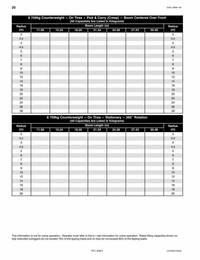
20 5479---0906---N4
RTC---8090 II Link-Belt Cranes
8 709kg Counterweight -- On Tires -- Pick & Carry (Creep) -- Boom Centered Over Front(All Capacities Are Listed In Kilograms)
Radius(m)
Boom Length (m) Radius(m)11.58 15.24 18.29 21.34 24.38 27.43 30.48
3 33.5 3.54 44.5 4.55 56 67 78 89 910 1012 1214 1416 1618 1820 2022 2224 2426 2628 28
8 709kg Counterweight -- On Tires -- Stationary -- 360˚ Rotation(All Capacities Are Listed In Kilograms)
Radius(m)
Boom Length (m) Radius(m)11.58 15.24 18.29 21.34 24.38 27.43 30.48
3 33.5 3.54 44.5 4.55 56 67 78 89 910 1012 1214 1416 1618 1820 20
This information is not for crane operation. Operator must refer to the in---cab information for crane operation. Rated lifting capacities shown onfully extended outriggers do not exceed 75% of the tipping loads and on tires do not exceed 65% of the tipping loads.

215479---0906---N4
RTC---8090 IILink-Belt Cranes
13 064kg Counterweight -- Fully Extended Outriggers -- 360˚ Rotation(All Capacities Are Listed In Kilograms)
Radius(m)
Boom Length (m) Radius(m)11.58 15.24 18.29 21.34 24.38 27.43 30.48 33.53 36.58 39.62 42.67
2.5 2.53 33.5 3.54 44.5 4.55 56 67 78 89 910 1012 1214 1416 1618 1820 2022 2224 2426 2628 2830 3032 3234 3436 3638 3840 40
This information is not for crane operation. Operator must refer to the in---cab information for crane operation. Rated lifting capacities shown onfully extended outriggers do not exceed 75% of the tipping loads and on tires do not exceed 65% of the tipping loads.

22 5479---0906---N4
RTC---8090 II Link-Belt Cranes
Fly Attachment Lift Capacity Charts -- Optional8 709kg Counterweight -- Fully Extended Outriggers -- 360˚ Rotation
(All Capacities Are Listed In Kilograms)42.67m Main Boom Length
2˚ Fly Offset42.67m Main Boom Length
15˚ Fly Offset
Radius(m)
Fly Length (m) Radius(m)
Fly Length (m)10.67 17.68 22.56 27.43 10.67 17.68 22.56 27.43
12 12
14 14
16 16
18 18
20 20
22 22
24 24
26 26
28 28
30 30
32 32
34 34
36 36
38 38
40 40
42 42
44 44
46 46
48 48
This information is not for crane operation. Operator must refer to the in---cab information for crane operation. Rated lifting capacities shown onfully extended outriggers do not exceed 75% of the tipping loads and on tires do not exceed 65% of the tipping loads.

235479---0906---N4
RTC---8090 IILink-Belt Cranes
8 709kg Counterweight -- Fully Extended Outriggers -- 360˚ Rotation(All Capacities Are Listed In Kilograms)
42.67m Main Boom Length30˚ Fly Offset
42.67m Main Boom Length45˚ Fly Offset
Radius(m)
Fly Length (m) Radius(m)
Fly Length (m)10.67 17.68 22.56 27.43 10.67 17.68 22.56 27.43
18 18
20 20
22 22
24 24
26 26
28 28
30 30
32 32
34 34
36 36
38 38
40 40
42 42
44 44
46 46
48 48
This information is not for crane operation. Operator must refer to the in---cab information for crane operation. Rated lifting capacities shown onfully extended outriggers do not exceed 75% of the tipping loads and on tires do not exceed 65% of the tipping loads.

24 5479---0906---N4
RTC---8090 II Link-Belt Cranes
13 064kg Counterweight -- Fully Extended Outriggers -- 360˚ Rotation(All Capacities Are Listed In Kilograms)
42.67m Main Boom Length2˚ Fly Offset
42.67m Main Boom Length15˚ Fly Offset
Radius(m)
Fly Length (m) Radius(m)
Fly Length (m)10.67 17.68 22.56 27.43 10.67 17.68 22.56 27.43
12 12
14 14
16 16
18 18
20 20
22 22
24 24
26 26
28 28
30 30
32 32
34 34
36 36
38 38
40 40
42 42
44 44
46 46
48 48
50 50
52 52
54 54
56 56
58 58
60 60
This information is not for crane operation. Operator must refer to the in---cab information for crane operation. Rated lifting capacities shown onfully extended outriggers do not exceed 75% of the tipping loads and on tires do not exceed 65% of the tipping loads.

255479---0906---N4
RTC---8090 IILink-Belt Cranes
13 064kg Counterweight -- Fully Extended Outriggers -- 360˚ Rotation(All Capacities Are Listed In Kilograms)
42.67m Main Boom Length30˚ Fly Offset
42.67m Main Boom Length45˚ Fly Offset
Radius(m)
Fly Length (m) Radius(m)
Fly Length (m)10.67 17.68 22.56 27.43 10.67 17.68 22.56 27.43
18 18
20 20
22 22
24 24
26 26
28 28
30 30
32 32
34 34
36 36
38 38
40 40
42 42
44 44
46 46
48 48
50 50
52 52
54 54
56 56
58 58
60 60
This information is not for crane operation. Operator must refer to the in---cab information for crane operation. Rated lifting capacities shown onfully extended outriggers do not exceed 75% of the tipping loads and on tires do not exceed 65% of the tipping loads.

26 5479---0906---N4
RTC---8090 II Link-Belt Cranes
This Page Intentionally Blank

275479---0906---N4
RTC---8090 IILink-Belt Cranes
This Page Intentionally Blank
5479---0906---N4
RTC---8090 II Link-Belt Cranes
Link--Belt Construction Equipment Company Lexington, Kentucky www.linkbelt.comRLink--Belt is a registered trademark. Copyright 2006. We are constantly improving our products and therefore reserve the right to change designs and specifications.