Embed Size (px)
Citation preview
A. F. Savas, E. Madan Iskorištavanje temperature plina dimnjaka i zraka za hlađenje peći za zagrijavanje tvornice metodom regeneriranja topline u keramičkim pećima
Tehnički vjesnik 22, 4(2015), 893-898 893
ISSN 1330-3651 (Print), ISSN 1848-6339 (Online) DOI: 10.17559/TV-20140228142025
UTILIZATION OF STACK GAS AND KILN COOLING AIR TEMPERATURE FOR FACTORY HEATING THROUGH HEAT RECOVERY METHOD IN CERAMIC KILNS Ahmet Fevzi Savas, Erhan Madan
Original scientific paper In this study an application in terms of heat recovery from stack gas temperature and waste hot air of tunnel kilns in ceramic industry was carried out. A heat exchanger was designed for the recovery of waste heat and was installed to each of the seven tunnel kilns. The heating of the closed factory area of 1.100 m2 was provided using the hot water obtained from the heat exchangers. As a result of this study an energy recovery of 3.509 kW·h was achieved. A natural gas saving of 2.513.000 m3 per year was generated through reuse of the obtained energy within the factory. The return period of the investment cost of this application on the current system being as short as 8,3 months has shown its usability for hot water production required especially in ceramic (vitrified) sector. Keywords: ceramic factory, heat exchanger, heat recovery Iskorištavanje temperature plina dimnjaka i zraka za hlađenje peći za zagrijavanje tvornice metodom regeneriranja topline u keramičkim pećima
Izvorni znanstveni članak Rad se bavi primjenom obnovljenje (regenerirane) topline dimnjačkog plina i potrošenog toplog zraka u tunel pećima u keramičkoj industriji. Konstruiran je izmjenjivač topline za regeneriranje potrošene topline te je ugrađen u svaku od sedam tunel peći. Grijanje zatvorene površine tvornice od 1.100 m2 omogućeno je korištenjem tople vode dobivene izmjenjivačima topline. Postignuta je regeneracija energije od 3.509 kW·h. Godišnja ušteda prirodnog plina od 2.513.000 m3 postignuta je ponovnim korištenjem dobivene energije u okviru tvornice. Period povrata utrošenih sredstava od samo 8,3 mjeseci pokazao je korisnost ove metode u proizvodnji tople vode, naročito u keramičkoj industriji. Ključne riječi: tvornica keramike, izmjenjivač topline, obnavljanje (regeneriranje) topline 1 Introduction
Today the demand for energy is increasing with each
passing day. Presently the majority of energy need worldwide is met by fossil fuels. The rapid depletion of fossil fuel reserves is also increasing environmental problems in addition to increased energy need and economic problems. Heavy energy use entails the responsibility of leaving a habitable blue planet to future generations as well as the pressure to be able to control costs. Therefore while alternative energy resources are sought to replace depleting fossil fuels on one hand, benefiting effectively and efficiently from the available resources gains currency on the other. Gradual decrease in energy resources has necessitated the industrial production to be made by spending minimum energy [1]. As a result energy consumption has become a significant cost parameter per industrial product. Besides taking place near the top in the order of the sectors that use energy heavily in the industry, iron-steel, cement, glass, ceramic and paper are the potential representatives of waste heat sources. So these sectors attract more attention for recovery of waste heat [2]. Approximately one third of the fossil fuels consumed in industrial processes in the United States of America consist of greenhouse gas emissions. This, in turn, leads to a rate between 20 % and 50 % of fossil fuels getting lost as waste heat [3]. Recovery of waste heat provides a tempting opportunity for both reducing greenhouse gas emissions and less energy cost.
Waste heat recovery systems are known as systems that enable reuse of the heat energy discharged from an industrial process. Such systems are used in industrial businesses that use high heat energy, and in various
engines [4, 5]. The addition of heat recovery system to a facility being economically viable depends on beneficial use of such waste heat as well as on the amount of recoverable waste heat being at an adequate level [6]. The recoverable waste heat amount is calculated based on measurements of facility parameters such as flow rate, temperature, humidity and pressure. Waste heat systems are construed under Gas-Gas heat recovery systems, Gas-Liquid heat recovery systems and Liquid-Liquid heat recovery systems titles. In a heat recovery process that contains waste hot air and burned gases one of the most important issues is the damage on heat exchanger surfaces caused by acids generated due to condensation on the heat exchanger surfaces. Therefore, when making heat recovery design, the temperature of heated fluid, its compositions and the maximum heat that the heated fluid can heat should be taken into account. Due to the acid generation of hot stack gas based on condensation when heat exchanger is designed, making a design in a way that the heat exchanger exit heat of the air does not drop below 120 °C is very important in terms of the efficiency and life of the hardware.
Since ceramic sector is an industrial branch that uses mineralogical process and is based on rocks and soil, energy use is heavy during production. Ceramics are non-metal inorganic materials that acquire the specified and desired properties under thermal applications. Ceramic sector is a heavy energy consuming sector due to drying and firing processes [7]. In ceramic production, high temperature stack gas and cooling air of kilns (waste hot air) constitute an important potential for heat recovery application. Thermal energy obtained through heat recovery methods applied to kilns can be used for numerous purposes, particularly for hot water, direct or
Utilization of stack gas and kiln cooling air temperature for factory heating through heat recovery method in ceramic kilns A. F. Savas, E. Madan
894 Technical Gazette 22, 4(2015), 893-898
indirect cooling, preheating of material to be put into the kiln and heating of combustion air for burners on the kiln.
Due to energy crisis, heat recovery has attracted some recent attention. In the study titled structural design optimization of hot air kiln exchangers, Aiqin Li has calculated the reduction of investment costs for spray heat exchanger and radiation recuperator used in high temperature hot air kilns through logarithmic average temperature difference method. He analysed the relationship between the temperature difference and average heat exchange area at various temperature points such as 0 °C, 100°C and 200 °C. He found out that the heat exchange area of spray heat exchanger is lower than that of recuperator heat exchanger under the same conditions [8]. In their gas techno-analysis method, Gang Xu et al. have carried out optimization design of a heat recovery system by using boiler exhaust. In this analysis, they determined the annual coal amount and coal income saving data for a 1000 MW typical power generation unit existing in China to be around 13.000 tons of coal and 1,56 million dollars at 90 °C exhaust gas temperature [9]. Chaojung Wang et al. have carried out a low pressure heat exchanger application for exhaust stack gas waste heat recovery in an electric power plant. In this application they have achieved 2 ÷ 4 g coal and under full load 25 ÷ 35 tons/h water saving per kW·h [10]. M. T. Zarrinefkahsf, S. M. Sadrameli developed a model to research performance of a fixed bed regenerative heat exchanger in the study named "fixed bed regenerative heat exchanger simulation for heat recovery of stack gas". They stated that effectiveness decreases with an increasing flow rate, change in effectiveness would not be very intense when change in flow rate is not very high, and efficiency increases through utilization of compact generator [11]. Hao Fanga et al. addressed making use of cement and copper plants in their study carried out regarding utilization of industrial waste heat with low temperature. They designed a project for heating a settlement at the northern China with a waste heat potential of 122 MW available in these plants and as a result, they increased thermal efficiency of the cement plant from 72,9 % to 74,3 % and thermal efficiency of the copper plant from 30,1 % to 74,7 %. Furthermore, they achieved an annual decrease of 168.644 tons in CO2 emission, 547 tons in SO2 emission, 476 tons in NOx emission and also water saving of 640.634 tons [12]. Zhiwei Li et al. examined electric energy production through utilization of waste heat from flat glass kiln by using natural gas and petroleum coke fuels. They determined that steam generation of 23 t/hour and power generation of approximately 5,2 MW generated from waste heat were the same for both natural gas and petroleum coke fuels. They stated that it corresponds to an annual energy saving of 31 million kW·h, equivalent coal of 12.400 tons and an energy saving of 0,84 MJ per kilogram of glass [13].
In M. Hatami et al. finned type heat exchanges with different fin dimensions in the exhaust of a gasoline engine are modeled numerically for improving the exhaust energy recovery [14].
In M. Hatami et al. a vortex generator heat exchanger is used to recover energy from the exhaust of a diesel engine. They make an experimental study and after
thermodynamical analyses, they get an optimization and the best operating condition [15].
In M. Hatami et al. a review of different heat exchangers designs for increasing the diesel exhaust waste heat recovery is presented [16].
M. Hatami et al. modelled (numerically) two cases of heat exchangers (HEXs) which were previously used in exhaust of internal combustion engines (ICEs). In this paper, engines exhaust waste heat is recovered by using the finned type heat exchangers numerically. Heat transfer through the walls and fins was modelled successfully and the transferred heat to cold fluid is calculated as the recovered heat. Results show that SST k–ω and RNG k–ε are suitable viscous models, but RSM has not good results compared to experimental outcomes. Also, graphs and contours reveal that recovered heat can be improved by increasing the fin numbers and length where maximum heat recovery occurs in high engine load and speeds [14]. Mohsen Ghazikhani et al. studied an experimental exhaust cooling in a DI diesel engine with the aim of energy recovery. The results reveal that amount of the recovered energy from the exhaust is affected by engine load and speeds, so the second law efficiency for cooling system is presented in wide range of load and engine speeds. It is shown that energy recovery from muffler cooling can be properly assumed as a part of engine power. In this case, the BSFC (brake specific fuel consumption) is reduced approximately 5 ÷ 15 % [5].
M. Hatami at. al. applied response surface methodology (RSM) based on central composite design (CCD) to obtain an optimization design of finned type heat exchangers (HEX) to recover waste heat from the exhaust of a diesel engine. For this aim, fifteen HEXs with different fin dimensions and six central points were designed numerically. Results show that height of the fins has more effect on pressure drop than fin numbers and thicknesses, while fin numbers have maximum effect to enhance the heat recovery. According to CCD optimization technique, a special design for finned heat exchanger is proposed to fill the gap in this area [17].
In this study, it was aimed that hot water need of ceramic factory heating air conditioners is met by waste heat. From heat of high temperature stack gas and cooling air (waste hot air) discharged from tunnel kilns using natural gas fuel, hot water with a temperature of 95 °C was obtained by using cross flow heat exchanger. The obtained hot water was used in heating serpentine coils of air conditioning plants. 2 Heat exchanger design
Heat exchangers used for different purposes in
different fields are classified according to heat exchange type, number of fluids, proportion of heat transfer surface to heat transfer volume (compact), structural characteristics, flow types and heat transfer mechanisms [18].
In designing of a heat exchanger two methods are typically used. The first is Logarithmic Mean Temperature Difference (LMTD) and the second is Number of Transfer Units (NTU). For example, logarithmic mean temperature difference and effectiveness are higher than all other flow regulations in
A. F. Savas, E. Madan Iskorištavanje temperature plina dimnjaka i zraka za hlađenje peći za zagrijavanje tvornice metodom regeneriranja topline u keramičkim pećima
Tehnički vjesnik 22, 4(2015), 893-898 895
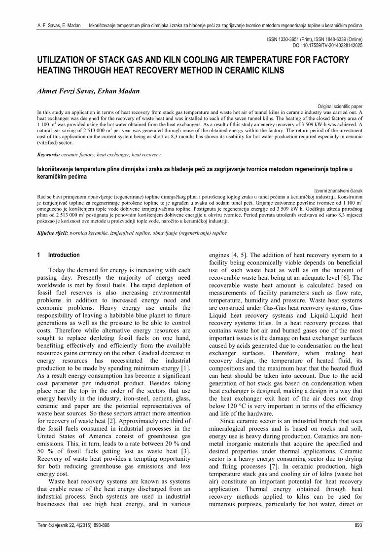
applications of cross-flow finned tube heat exchanger and counter flow heat exchanger, as seen in Fig. 1. Due to this advantage, these types of heat exchangers are generally preferred in practice [19, 20, 21]. In this work, LMTD method is used. In this chapter, we obtain the formulae that will be used later.
Figure 1 Cross-flow finned tube heat exchanger
The general heat balance for heat exchanger as
constant flow can be written as �̇�𝑄ℎ the heat given by the hot fluid below, �̇�𝑄𝑐𝑐 the heat received by the cold fluid with the recognition that it is merely heat exchange between fluids, there is no heat loss to the environment. �̇�𝑄ℎ = 𝑄𝑄�̇�𝑐 . (1)
The mass flow of the hot fluid 𝑚𝑚1̇ (kg/s) and its specific heat at constant pressure 𝐶𝐶𝑝𝑝,1 (J/kg·K) heat exchangers input temperature 𝑇𝑇1,in (K) output temperature 𝑇𝑇1,out (K). If we rewrite the energy equation by neglecting the constant flowing kinetic and potential energy changes where the mass flow of the cold fluid 𝑚𝑚2̇ (kg/s) and its specific heat at constant pressure 𝐶𝐶𝑝𝑝,2 (J/kg·K) heat exchanger input temperature 𝑇𝑇2,in (K) output temperature 𝑇𝑇2,out (K);
��̇�𝑚𝐶𝐶𝑝𝑝�1�𝑇𝑇1,in − 𝑇𝑇1,out� = ��̇�𝑚𝐶𝐶𝑝𝑝�2�𝑇𝑇2,in − 𝑇𝑇2,out�. (2) By Fig. 1 and Eq. (2), logarithmic mean temperature difference for cross-flow finned tube heat exchanger is obtained as
∆𝑇𝑇𝑙𝑙𝑙𝑙 = �𝑇𝑇1,out−𝑇𝑇2,in�−�𝑇𝑇1,in−𝑇𝑇2,out�
𝑙𝑙𝑙𝑙��𝑇𝑇1,out−𝑇𝑇2,𝑖𝑖𝑖𝑖�/�𝑇𝑇1,in−𝑇𝑇2,out�� . (3)
Using the same method, the actual heat transfer rate is written as the following by using average temperature difference; �̇�𝑄 = 𝑈𝑈𝑈𝑈∆𝑇𝑇𝑙𝑙𝑙𝑙 , (4) where U is the total heat transfer coefficient (W/m2·K) and A is the heat transfer surface (m2). 3 Application of heat exchangers
In this section, we introduce the application of heat
exchangers. Firing process of ceramic products is carried out in 7 tunnel kilns in the factory. While approximately 30 % of the fuel energy used in these kilns is emitted to the atmosphere as stack gas, 37 % thereof is emitted as cooling stack gas (waste hot air heat). In this study, recovery of stack gas temperature of four kilns and recovery of waste hot air heat of the other three kilns was studied. In the heat exchanger design made according to stack gas heat, exit temperature of hot gas from heat exchanger was determined as 120 °C. The reason for choosing this temperature is that sulphide and alike substances arising from burned funnel gas and ceramic materials are condensed under 120 °C and cause acidic damage on steel surfaces. In the heat exchanger design made according to cooling funnel hot air heat, exit temperature of hot gas from heat exchanger was determined as 100 °C. This temperature was chosen because it does not contain burned gas, and acid and alike substances which would form under 120 °C and damage the heat exchanger, do not exist. For energy recovery, heat exchanger with double flow, single pass and counter current, in which there can be no direct contact between fluids and which has finned tube, was designed. The energy recovered with heat exchanger was transferred to the hot water heating (air-conditioning) system used in heating of the factory. Hot water heating system of the factory is hot water pressurized to 95 ÷ 70 °C and 4 bars. Before heat exchanger was inserted to the tunnel kilns, 3 hot water boilers were being used for heating the factory's indoor area which is 110.000 m2 in total. Total capacity of these boilers was 17.500.000 kcal/h and they were consuming 2.850.000 m3 natural gas per year. This energy spent for heating (air-conditioning) of the facility environment was approximately 12 % of the total natural gas consumption of the facility.
In this study, by Eq. (2), heat exchanger capacities were calculated at the first step by using stack gas flow rates and temperatures of tunnel kilns, and heating installation operating temperature data. A heat exchanger was designed for the kilns no 1, 2, 3 and 4 by using stack gas flow rates of ceramic tunnel kilns in the factory. For
Utilization of stack gas and kiln cooling air temperature for factory heating through heat recovery method in ceramic kilns A. F. Savas, E. Madan
896 Technical Gazette 22, 4(2015), 893-898
the kilns no 1, 2, 3, 4 , the capacity of the heat exchanger, which was designed for the temperature conditions of 350 °C for stack gas intake, 120 °C for stack gas exit and 70 °C for water intake, 95 °C for water exit, was calculated as 417 kW·h. For the kilns no 5 and 6, the capacity of the heat exchanger, which was designed for the temperature conditions of 250 °C for hot air intake, 100 °C hot air exit and 70 °C water intake, 95 °C water exit, was calculated as 502 kW·h by using waste hot air flow rates of cooling air funnel. Similarly, for the kiln no 7, the capacity of the heat exchanger was calculated as 837 kW·h by using waste hot air flow rates of cooling air funnel. By Eq. (4),
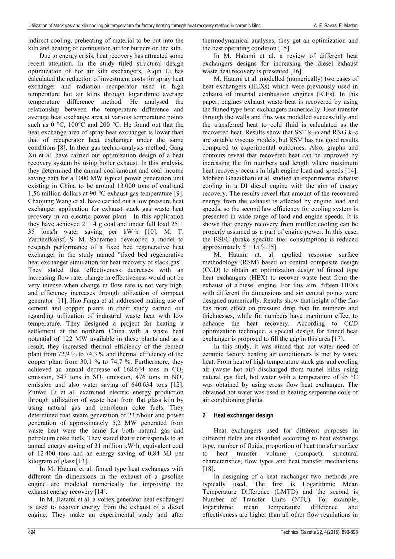
Heat exchangers were manufactured and installed according to such calculated capacity data. In Fig. 2, connection diagrams for funnels, heat exchangers, hot water boilers and air conditioning units of tunnel kilns in the factory were shown.
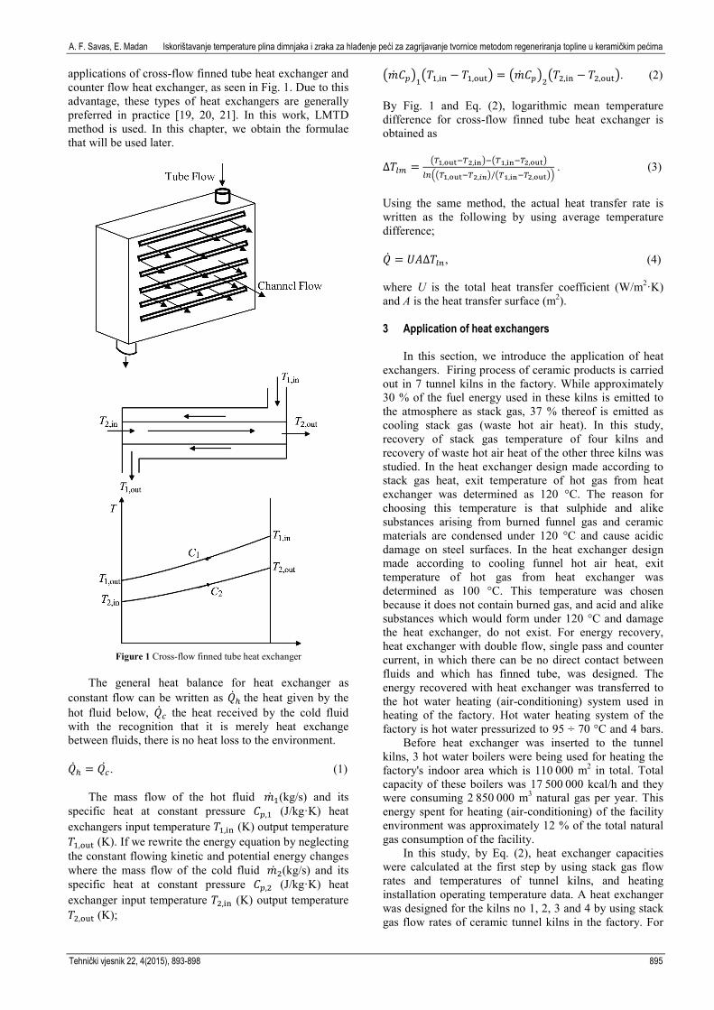
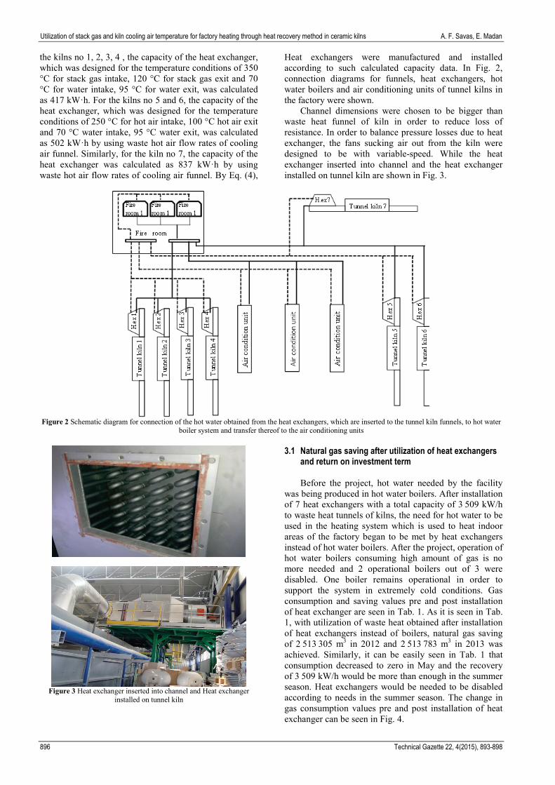
Channel dimensions were chosen to be bigger than waste heat funnel of kiln in order to reduce loss of resistance. In order to balance pressure losses due to heat exchanger, the fans sucking air out from the kiln were designed to be with variable-speed. While the heat exchanger inserted into channel and the heat exchanger installed on tunnel kiln are shown in Fig. 3.
Figure 2 Schematic diagram for connection of the hot water obtained from the heat exchangers, which are inserted to the tunnel kiln funnels, to hot water
boiler system and transfer thereof to the air conditioning units
Figure 3 Heat exchanger inserted into channel and Heat exchanger
installed on tunnel kiln
3.1 Natural gas saving after utilization of heat exchangers and return on investment term
Before the project, hot water needed by the facility
was being produced in hot water boilers. After installation of 7 heat exchangers with a total capacity of 3.509 kW/h to waste heat tunnels of kilns, the need for hot water to be used in the heating system which is used to heat indoor areas of the factory began to be met by heat exchangers instead of hot water boilers. After the project, operation of hot water boilers consuming high amount of gas is no more needed and 2 operational boilers out of 3 were disabled. One boiler remains operational in order to support the system in extremely cold conditions. Gas consumption and saving values pre and post installation of heat exchanger are seen in Tab. 1. As it is seen in Tab. 1, with utilization of waste heat obtained after installation of heat exchangers instead of boilers, natural gas saving of 2.513.305 m3 in 2012 and 2.513.783 m3 in 2013 was achieved. Similarly, it can be easily seen in Tab. 1 that consumption decreased to zero in May and the recovery of 3.509 kW/h would be more than enough in the summer season. Heat exchangers would be needed to be disabled according to needs in the summer season. The change in gas consumption values pre and post installation of heat exchanger can be seen in Fig. 4.

A. F. Savas, E. Madan Iskorištavanje temperature plina dimnjaka i zraka za hlađenje peći za zagrijavanje tvornice metodom regeneriranja topline u keramičkim pećima
Tehnički vjesnik 22, 4(2015), 893-898 897
Total cost and annual return of 7 heat exchangers installed in ceramic kilns is shown in Tab. 2. In the calculations, natural gas unit price was taken as 0,75 TRY/m3, which is the unit price in 2012. In calculation of
return on investment term for heat exchangers, interests and other financial expenses were disregarded. The return on investment term is 8,3 months (0,69 year).
Table 1The change in gas consumption values pre and post installation of heat exchanger
Months 2011 Pre-application
Natural gas consumption (m3)
2012 Pre-application Natural gas
consumption (m3)
2012 Post-application Natural gas
consumption (m3)
2013 Post-application Natural gas
consumption (m3)
2013 Post-application Natural
gas Saving (m3) January 390,032 120,032 270,000 126,822 263,210 February 355,612 70,134 285,478 88,665 266,947 March 325,600 34,911 290,689 54,255 271,345 April 305,200 36,653 268,547 9,192 296,008 May 275,414 0 275,414 0 275,414 June 120,215 0 120,215 0 120,215 July 40,219 0 40,219 0 40,219 August 25,512 0 25,512 0 25,512 September 50,218 0 50,218 0 50,218 October 275,625 2,817 272,808 13,503 262,122 November 326,218 27,111 299,107 12,949 313,296 December 384,689 69,591 315,098 55,412 329,277
Total: 2,874,554 361,249 2,513,305 292,437 2,513,783
Figure 4 The change in gas consumption (m3) pre and post installation of heat exchanger
Table 2 Heat Exchanger investment amount, total saving
amount and return on investment term
Kiln No Capacity (kW/h)
Investment Amount (TRY)
Total Natural Gas Saving (m3)
Kiln 1 Stack Gas Heat Exchanger 417 120,000
2,51
3,00
0 m
3
Kiln 2 Stack Gas Heat Exchanger 417 120,000
Kiln 3 Stack Gas Heat Exchanger 417 120,000
Kiln 4 Stack Gas Heat Exchanger 417 120,000
Kiln 5 Hot Air Heat Exchanger 502 225,000
Kiln 6 Hot Air Heat Exchanger 502 225,000
Kiln 7 Hot Air Heat Exchanger 837 375,000
Total Investment Amount (TRY): 1,305,000 Total Saving Amount (TRY/Year): 1,884,750 Heat Exchanger Return on Investment Term
(Year): 0,69
4 Conclusion
If utilization of waste heat is considered in a facility, usage area of waste heat should be determined and its efficiency should be elaborately analysed at the first step. If there is no appropriate usage area for recovered energy or it is not efficient, it would cause its return on investment term to be extended and company managements to approach with suspicion to heat recovery. After this stage, return on investment term for the system should be calculated through cost benefit analyses and it should provide guidance for financial decisions with its benefits and gains.
In this study, 4 heat exchangers were designed in order to make use of stack gas of 7 tunnel type ceramic kilns in the facility and 3 heat exchangers were designed in order to make use of waste hot air heat. As a result of utilization of the heat exchangers, an energy recovery of 3,056 kWh in total was achieved. Annual natural gas
Utilization of stack gas and kiln cooling air temperature for factory heating through heat recovery method in ceramic kilns A. F. Savas, E. Madan
898 Technical Gazette 22, 4(2015), 893-898
amount corresponding to this energy saving is 2,513,305 m3. The obtained results show the financial extent which waste heat emitted from the kilns in the ceramic sanitary ware sector has reached. Return on investment term of this application being as short as 0,69 year showed its usability for hot water production needed particularly in the sanitary ware sector.
Nomenclature A Heat transfer area (m2) Cp Specific heat at constant pressure (J/kg∙K) H.ex Heat exchanger m Mass flow rate (kg/s) T Temperature (K) Q Heat transfer rate (W) U Overall heat transfer coefficient (W/m2·K) ΔTln Average logarithmic temperature difference Subscripts in Inlet out Outlet Acknowledgements
The authors would like to thank Editor for his/her efforts on the paper and thanks are also due to the anonymous referees for helpful suggestions and improvements on the paper. 5 References [1] Christos, A.; Theochairs, T. Energy saving technologies in
the European ceramic sector: asystematic review. // Applied Thermal Engineering. 21, (2001), pp. 1231-1249. DOI: 10.1016/S1359-4311(01)00006-0
[2] Waste Heat to Power System, last updated May 30, 2013 http://www.epa.gov/chp/documents/waste_heat_power.pdf.
[3] Waste Heat Recovery: Technology and Opportunities in US Industry, US Department of Energy, Prepared by BCS, Incorporated, March 2008.
[4] Waste Heat Recovery in the Process Industries. Good practice. Didcot (Oxfordshire): Department of the Environment, Transport and the Regions: 1996.
[5] Ghazikhani, M.; Hatami, M.; Ganji, D. D.; Gorji-Bandpy, M.; Behravan, A.; Shahi, G. Energy recovery from the exhaust cooling in a DI diesel engine for BSFC reduction purposes. // Energy. 65, (2014), pp. 44-51. DOI: 10.1016/j.energy.2013.12.004
[6] Hao Fanga; Jianjun Xia; Kan Zhua; Yingbo Sub; Yi Jianga. Heat exchangers for energy recovery in waste and biomass to energy technology -I. Energy recovery from flue gas. // Applied Thermal Engineering. 64, 1-2(2012), pp. 1231-1249.
[7] Cassani, F. RecuperandoEnergia dos Fornos, Secadores e Atomizadores. // Revista Cerâmica Industrial. 14, 3(2009).
[8] Aiqin Li. Study on Structural Optimization Design of Heat Exchangers of Hot air furnace. // 2011 2nd International Conference on Advances in Energy Engineering, Energy Procedia. 14, (2012), pp. 1317-1322.
[9] Xu Shengwei Huang; Yongping Yang; Ying Wu; Kai Zhang; Cheng Xu. Techno-economic analysis and optimization of the heat recovery of utility boiler flue gas. // Applied Energy. 112, (2013), pp. 907-917. DOI: 10.1016/j.apenergy.2013.04.048
[10] Boshu He; Shaoyang Sun; Xiaohui Pei; Ying Wu; Na Yan; Linbo Yan. Application of a low pressure economizer for waste heat recovery from the exhaust flue gas in a 600 MW power plant. // Energy. (2012), pp. 196-202.
[11] Zarrinefkahsf, M. T.; Sadrameli, S. M. Simulation of fixed bed regenerative heat exchangers for flue gas heat recovery. // Applied Thermal Engineering. 24, (2004), pp. 373-382. DOI: 10.1016/j.applthermaleng.2003.08.005
[12] Hao Fanga; Jianjun Xia; Kan Zhua; Yingbo Sub; Yi Jianga. Industrial waste heat utilization for low temperature district heating. // Energy Policy. 62, (2013), pp. 236-246. DOI: 10.1016/j.enpol.2013.06.104
[13] Zhiwei Li; Xiujin He; Yongqing Wanga; Bo Zhang; Hongzhou He. Design of a flat glass furnace waste heat power generation system. // Applied Thermal Engineering. 63, (2014), pp. 290-296. DOI: 10.1016/j.applthermaleng.2013.10.038
[14] Hatami, M.; Ganji, D. D.; Gorji-Bandpy, M. Numerical study of finned type heat exchangers for ICEs exhaust waste heat recovery. // Case Studies in Thermal Engineering. 4, (2014), pp. 53-64. DOI: 10.1016/j.csite.2014.07.002
[15] Hatami, M.; Jafaryar, M.; Ganji, D. D.; Gorji-Bandpy, M. Numerical study of finned type heat exchangers for ICEs exhaust waste heat recovery. // International Communications in Heat and Mass Transfer. 57, (2014), pp. 254-263. DOI: 10.1016/j.icheatmasstransfer.2014.08.015
[16] Hatami, M.; Ganji, D. D.; Gorji-Bandpy, M. A review of different heat exchangers designs for increasing the diesel exhaust waste heat recovery. // Renewable and Sustainable Energy Reviews. 37, (2014), pp. 168-181. DOI: 10.1016/j.rser.2014.05.004
[17] Hatami, M.; Ganji, D. D.; Gorji-Bandpy, M. CFD simulation and optimization of ICEs exhaust heat recovery using different coolants and fin dimensions in heat exchanger. // Neural Computing and Applications. 25, (7-8) (2014), pp. 2079-2090. DOI: 10.1007/s00521-014-1695-9
[18] Shah, R. K.; Sekulic, D. P. Fundamentals of heat exchanger design, John Wiley & Sons Inc., USA, 2003. DOI: 10.1002/9780470172605
[19] Genceli, O. F. Heat exchanger, Birsen Yayınevi, İstanbul, Turkey, 2005.
[20] Kakaç, S.; Liu, H. Heat exchangers selection, rating and thermal desing, CRC press, USA, 2002.
[21] Rohsenow, W. M.; Hartnett, J. P. Handbook of Heat Transfer, McGraw-Hill Book Company, New York, 1973.
Authors’ addresses Ahmet Fevzi Savas, Dr. Bilecik Seyh Edebali University 11210 Bilecik, Turkey E-mail: [email protected] Erhan Madan Eczacibasi Yapi Gerecleri Eskisehir Karayolu Uzeri 4. Km 11300 Bozuyuk, Bilecik, Turkey E-mail: [email protected]


![[KKLR] Madan Vanadis](https://img.pdfslide.tips/doc/110x75/55cf9679550346d0338bb7a0/kklr-madan-vanadis.jpg)


![[KKLR] Madan Vanadis 02](https://img.pdfslide.tips/doc/110x75/55cf9679550346d0338bb7a9/kklr-madan-vanadis-02.jpg)