Embed Size (px)
Citation preview

A Flexible Scene Representation for 3D Reconstruction Using an RGB-D Camera
Diego ThomasNational Institute of Informatics
Chiyoda, Tokyo, Japandiego [email protected]
Akihiro SugimotoNational Institute of Informatics
Chiyoda, Tokyo, [email protected]
Abstract
Updating a global 3D model with live RGB-D measure-ments has proven to be successful for 3D reconstructionof indoor scenes. Recently, a Truncated Signed DistanceFunction (TSDF) volumetric model and a fusion algorithmhave been introduced (KinectFusion), showing significantadvantages such as computational speed and accuracy ofthe reconstructed scene. This algorithm, however, is expen-sive in memory when constructing and updating the globalmodel. As a consequence, the method is not well scalableto large scenes. We propose a new flexible 3D scene repre-sentation using a set of planes that is cheap in memory useand, nevertheless, achieves accurate reconstruction of in-door scenes from RGB-D image sequences. Projecting thescene onto different planes reduces significantly the size ofthe scene representation and thus it allows us to generate aglobal textured 3D model with lower memory requirementwhile keeping accuracy and easiness to update with liveRGB-D measurements. Experimental results demonstratethat our proposed flexible 3D scene representation achievesaccurate reconstruction, while keeping the scalability forlarge indoor scenes.
1. Introduction
The fine 3D reconstruction of large indoor scenes from
RGB-D measurements is of wide interest for the computer
vision community, with various potential applications. For
example, 3D models of indoor scenes can be used in seri-
ous games or indoor space organization. With recent efforts
on developing inexpensive depth sensors such as the Mi-
crosoft Kinect camera or the Asus Xtion Pro camera (also
called RGB-D cameras), capturing depth information in in-
door environments becomes an easy task. This new set-up
opens new possibilities for 3D reconstruction, and several
softwares have been already proposed to realize live 3D re-
construction using RGB-D cameras.
In general, the live 3D reconstruction process can be di-
vided into 4 steps: (1) RGB-D measurement acquisition;
(2) camera tracking; (3) integration (or fusion) of aligned
RGB-D measurements and (4) 3D modeling (3D textured
mesh generation for example). The objective is then to carry
out these tasks with both computational efficiency and high
accuracy. Computational speed is important because we ex-
pect to capture many depth images (30 fps for the Kinect
camera), so each image needs to be processed quickly in or-
der to process the full sequence in a reasonable time. Even
for an off-line application, the amount of data that is pro-
cessed at each iteration imposes the use of graphic cards
with large parallel computational power, but available mem-
ory space is limited. On the other hand, accuracy of the
output 3D model is also important; in particular when we
want it to be usable in games, simulations or visualization
tasks. Using all available measurements including color is
expected to achieve the accurate 3D reconstruction.
A standard approach to 3D reconstruction using RGB-D
cameras is to employ a frame-to-frame strategy [8, 10, 11].
Each incoming frame is aligned to its previous frame, then
newly aligned data are integrated into a global model (using
surfels [15] for example), which is triangulated in a final
post-process (using poisson surface reconstruction [12] for
example). A crucial limitation of this strategy comes from
the frame-to-frame error propagation, which can lead to sig-
nificant errors at the end of the sequence. This becomes
fatal when the scale of the scene is large. A loop closure
algorithm may reduce the propagated error if a loop exists.
However, its effectiveness is limited as the whole sequence
has to be processed again to fuse all measurements after
correcting the estimated camera trajectory and, moreover,
loops are not always available. In this approach, only the
current and previous frames are loaded on the GPU mem-
ory for camera tracking and, therefore, the GPU memory
use is low and tracking is fast.
Another approach to 3D reconstruction is to use the
frame-to-global-model strategy, which has been proven ef-
fective with KinectFusion [13] and its extensions [14, 16,
21]. In this strategy, a single high-quality global 3D model
is updated along with live depth measurements, where the
global model is represented as a signed distance function
that is discretized into a volume covering the scene to be
2013 IEEE International Conference on Computer Vision
1550-5499/13 $31.00 © 2013 IEEE
DOI 10.1109/ICCV.2013.348
2800
reconstructed. Incoming depth images are then aligned
to high-quality predicted depth images generated from the
global model. Using a global model allows to reduce the er-
ror propagation, however, the volumetric representation of
the scene is highly memory consuming. As a consequence,
most of the GPU memory space is used to update the global
model and generate depth images. Thus additional opera-
tions on the GPU that require significant memory (such as
SIFT-GPU) are not executable. Feature appearance based
alignment methods, for example, cannot be used to augment
the ICP based pose estimation. Accordingly, without rich
geometric features in RGB-D image sequences, the method
does not work well. In addition, the method is not well scal-
able to large scenes. Extensions of KinectFusion have been
proposed where the volume is moved along with the camera
to reconstruct large indoor scenes. However, rich geomet-
ric features are still required for camera tracking. Existing
volumetric methods cannot deal with an RGB-D image se-
quence whose part has poor geometric features (like when
passing through a corridor for example).
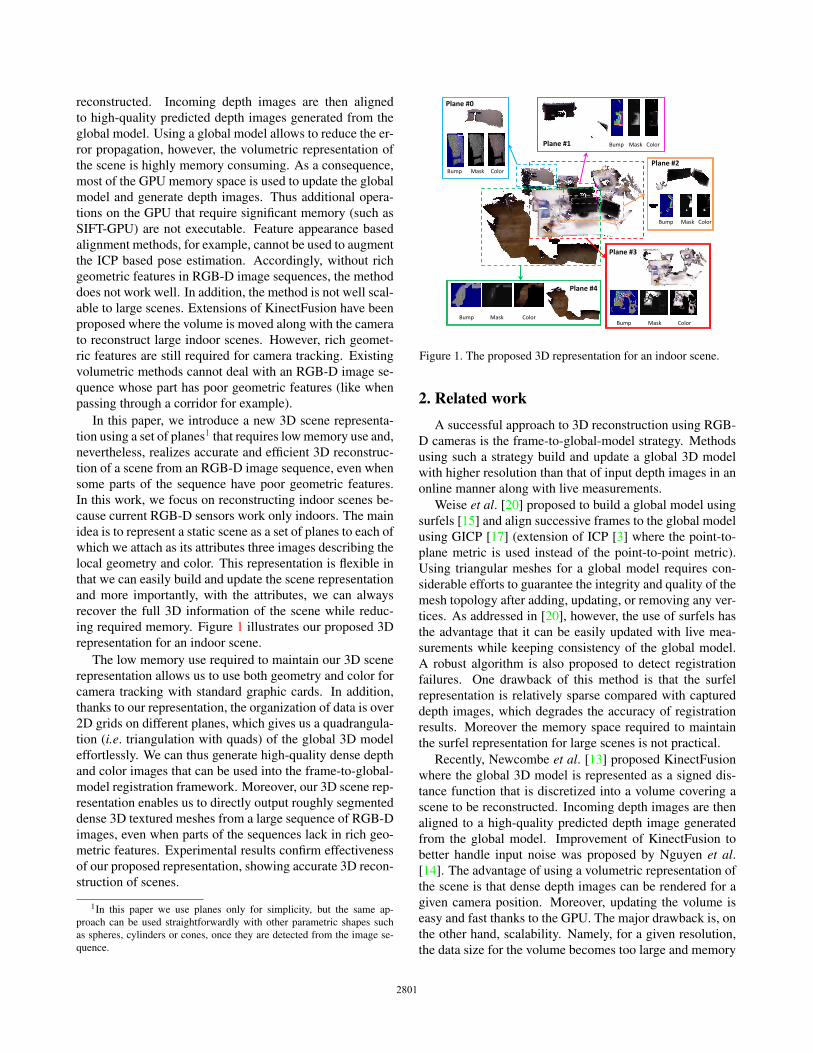
In this paper, we introduce a new 3D scene representa-
tion using a set of planes1 that requires low memory use and,
nevertheless, realizes accurate and efficient 3D reconstruc-
tion of a scene from an RGB-D image sequence, even when
some parts of the sequence have poor geometric features.
In this work, we focus on reconstructing indoor scenes be-
cause current RGB-D sensors work only indoors. The main
idea is to represent a static scene as a set of planes to each of
which we attach as its attributes three images describing the
local geometry and color. This representation is flexible in
that we can easily build and update the scene representation
and more importantly, with the attributes, we can always
recover the full 3D information of the scene while reduc-
ing required memory. Figure 1 illustrates our proposed 3D
representation for an indoor scene.
The low memory use required to maintain our 3D scene
representation allows us to use both geometry and color for
camera tracking with standard graphic cards. In addition,
thanks to our representation, the organization of data is over
2D grids on different planes, which gives us a quadrangula-
tion (i.e. triangulation with quads) of the global 3D model
effortlessly. We can thus generate high-quality dense depth
and color images that can be used into the frame-to-global-
model registration framework. Moreover, our 3D scene rep-
resentation enables us to directly output roughly segmented
dense 3D textured meshes from a large sequence of RGB-D
images, even when parts of the sequences lack in rich geo-
metric features. Experimental results confirm effectiveness
of our proposed representation, showing accurate 3D recon-
struction of scenes.
1In this paper we use planes only for simplicity, but the same ap-
proach can be used straightforwardly with other parametric shapes such
as spheres, cylinders or cones, once they are detected from the image se-
quence.
Plane #0
Bump Mask Color
Plane #1 Bump Mask Color
Plane #2
Bump Mask Color
Bump Mask Color
Plane #3
Plane #4
Bump Mask Color
Figure 1. The proposed 3D representation for an indoor scene.
2. Related workA successful approach to 3D reconstruction using RGB-
D cameras is the frame-to-global-model strategy. Methods
using such a strategy build and update a global 3D model
with higher resolution than that of input depth images in an
online manner along with live measurements.
Weise et al. [20] proposed to build a global model using
surfels [15] and align successive frames to the global model
using GICP [17] (extension of ICP [3] where the point-to-
plane metric is used instead of the point-to-point metric).
Using triangular meshes for a global model requires con-
siderable efforts to guarantee the integrity and quality of the
mesh topology after adding, updating, or removing any ver-
tices. As addressed in [20], however, the use of surfels has
the advantage that it can be easily updated with live mea-
surements while keeping consistency of the global model.
A robust algorithm is also proposed to detect registration
failures. One drawback of this method is that the surfel
representation is relatively sparse compared with captured
depth images, which degrades the accuracy of registration
results. Moreover the memory space required to maintain
the surfel representation for large scenes is not practical.
Recently, Newcombe et al. [13] proposed KinectFusion
where the global 3D model is represented as a signed dis-
tance function that is discretized into a volume covering a
scene to be reconstructed. Incoming depth images are then
aligned to a high-quality predicted depth image generated
from the global model. Improvement of KinectFusion to
better handle input noise was proposed by Nguyen et al.[14]. The advantage of using a volumetric representation of
the scene is that dense depth images can be rendered for a
given camera position. Moreover, updating the volume is
easy and fast thanks to the GPU. The major drawback is, on
the other hand, scalability. Namely, for a given resolution,
the data size for the volume becomes too large and memory
2801
consuming when the target scene becomes large.
Extensions of KinectFusion to a large scene have been
proposed where the volume is moved along with the tracked
camera motion. Roth et al. [16] proposed a method to au-
tomatically translate and rotate the volume in space as the
camera moves. The volume is remapped into a new one by
the Truncated Signed Distance Function (TSDF) interpola-
tion whenever sufficient camera movement is observed. The
objective of this work is to output fine camera tracking with
a local map of the environment. As a consequence, points
that leave the volume are lost and the method can not gen-
erate the complete reconstructed scene. Similarly, Whelan
et al. [21] introduced Kintinuous, proposing a method to
identify points that leave the KinectFusion volume and in-
crementally add them into a triangular mesh representation
of the scene. Available implementation that can be found in
the PCL [1] allows even to re-use existing data when mov-
ing the volume. However, rich geometric features in the
RGB-D image sequence are required for accurate scene re-
construction. When a scene does not have rich geometric
features, this method fails in tracking the camera motion,
resulting in poor reconstruction.
Much recently, Zeng et al. [22] and Chen et al. [6] pro-
posed an octree-based fusion method to compress the vol-
umetric TSDF representation of the scene. At the same
time, Zhou et al. [23] proposed to use local volumes around
points of interest and Henry et al. [9] proposed to segment
the scene into planar patches and use 3D TSDF volumes
around them to represent the 3D scene. By contrast, our
proposed method requires only three 2D images for each
plane to model the scene, which allows more compact rep-
resentation of the scene.
As the size of the scene to be reconstructed becomes
large, representing the whole scene using clouds of points
or volumes becomes unpractical. The more points that com-
pose the scene exist, the heavier the post processing such
as triangulation or texturing becomes. In this paper we
propose a scene representation that allows to directly build
roughly segmented 3D textured meshes from an RGB-D im-
age sequence.
3. Scene representation using planes
For 3D scene reconstruction using RGB-D cameras, how
to represent the target scene is of crucial importance. The
representation should be (1) compact, so that the user can
reconstruct large scenes, (2) accurate for fine reconstruc-
tion, (3) easy to update with live measurements for fast pro-
cessing, and (4) capable of predicting dense high-quality
RGB-D images for accurate camera tracking. To the best of
our knowledge, there is no 3D representation that satisfies
these four requirements, which motivates us to introduce a
new flexible 3D scene representation.
We reason that parametric shapes such as planes can be
used to describe an indoor scene because it is mainly com-
posed of man-made objects (such as table, wall and storage
for example), with rather simple shapes. We thus propose to
represent a scene as a set of planes (again only for simplic-
ity) having attributes. To each plane2 detected in the scene,
we attach as its attributes three 2D images in addition to
information that identifies the plane (planar patch).
The three images are a three-channel Bump image, an
one-channel Mask image and a three-channel Color image;
these three images encode the geometric and color details
of the scene. The Bump image encodes the local geometry
around the plane. For each pixel, we record in the three
channels the displacement of the 3D point corresponding to
the pixel from the lower left-corner of the pixel. The Mask
image encodes the confidence for the accumulated data at a
point and the Color image encodes the color of each point.
The Bump image encodes the local geometry, which al-
lows us to accurately represent the geometry of the 3D scene
while using less memory. This satisfies the first two require-
ments. In addition, adding, removing or updating points is
executed easily and efficiently, because we are manipulat-
ing 2D images. Therefore we satisfy the third requirement.
Last but not least, the organization of points over 2D images
gives a natural quadrangulation for the reconstructed scene.
We choose quads rather than triangles because the quadran-
gulation is a natural meshing for a 2D grid (also the number
of quads becomes smaller than that of triangles when gener-
ating meshes). We can thus render 3D textured meshes from
an estimated camera pose to obtain a high-quality dense pre-
dicted RGB-D image from the global model using 3D ren-
derers such as OpenGL. Our proposed 3D representation
thus satisfies the fourth requirement as well.
3.1. Plane detection
We detect different planes that decompose the target
scene by modifying the method proposed in [4] (we employ
the Floyd-Warshall algorithm [7] to detect local maxima).
We choose this voting strategy rather than another one such
as RANSAC [18], Generalized PCA [19] or Robust PCA [5]
because it is known to be fast with decent accuracy. Note
that for our 3D representation the accuracy of detected plane
parameters is not critical. Any errors that arise during the
plane detection will be compensated by the Bump image.
For each point in a given depth image, we first compute
its normal vector and generate a histogram of normals from
the depth image. Namely, each point votes in the bin corre-
sponding to its normal vector. Then, the bins with sufficient
votes are detected and connected bins are merged using the
Floyd-Warshall algorithm [7]. The median normal vector
for each connected class is then computed. We thus ob-
2Since a visible region of a plane in the scene has a finite size, a planar
patch may be more appropriate, however, we use the word plane for sim-
plicity. We remark that, in our method, each plane is identified by its plane
equation and a bounding box.
2802
Global coordinate system
d
axis
axis Plane
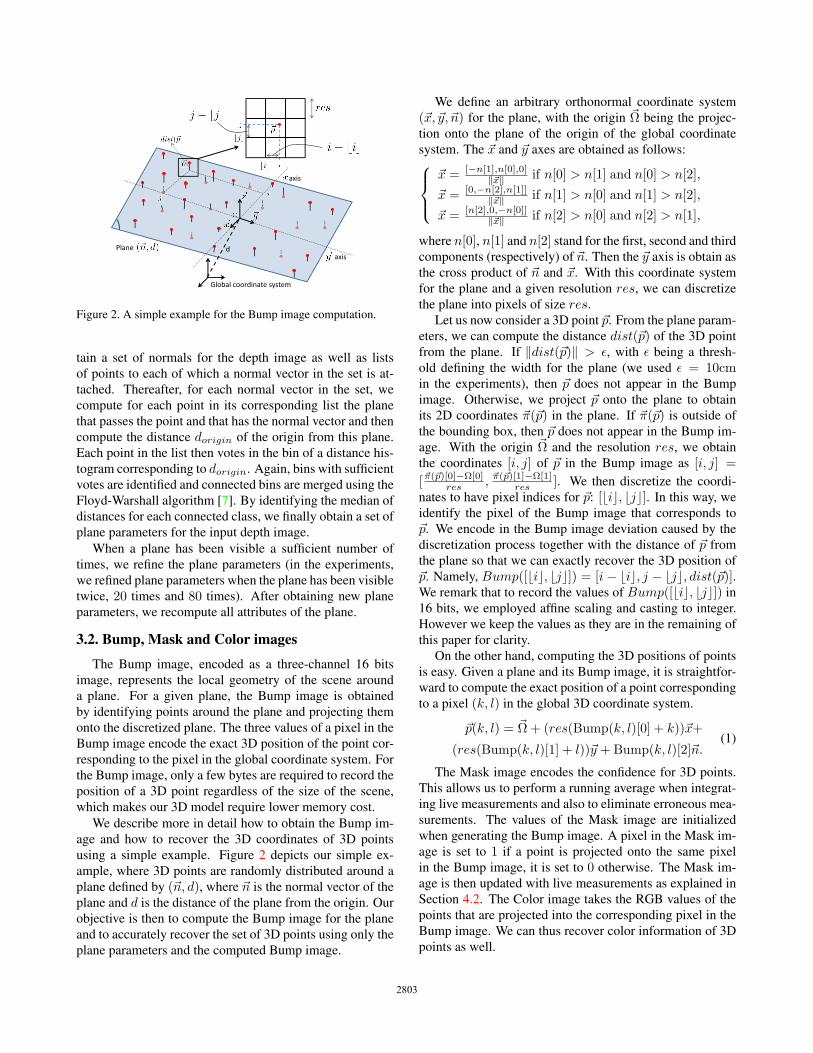
Figure 2. A simple example for the Bump image computation.
tain a set of normals for the depth image as well as lists
of points to each of which a normal vector in the set is at-
tached. Thereafter, for each normal vector in the set, we
compute for each point in its corresponding list the plane
that passes the point and that has the normal vector and then
compute the distance dorigin of the origin from this plane.
Each point in the list then votes in the bin of a distance his-
togram corresponding to dorigin. Again, bins with sufficient
votes are identified and connected bins are merged using the
Floyd-Warshall algorithm [7]. By identifying the median of
distances for each connected class, we finally obtain a set of
plane parameters for the input depth image.
When a plane has been visible a sufficient number of
times, we refine the plane parameters (in the experiments,
we refined plane parameters when the plane has been visible
twice, 20 times and 80 times). After obtaining new plane
parameters, we recompute all attributes of the plane.
3.2. Bump, Mask and Color images
The Bump image, encoded as a three-channel 16 bits
image, represents the local geometry of the scene around
a plane. For a given plane, the Bump image is obtained
by identifying points around the plane and projecting them
onto the discretized plane. The three values of a pixel in the
Bump image encode the exact 3D position of the point cor-
responding to the pixel in the global coordinate system. For
the Bump image, only a few bytes are required to record the
position of a 3D point regardless of the size of the scene,
which makes our 3D model require lower memory cost.
We describe more in detail how to obtain the Bump im-
age and how to recover the 3D coordinates of 3D points
using a simple example. Figure 2 depicts our simple ex-
ample, where 3D points are randomly distributed around a
plane defined by (�n, d), where �n is the normal vector of the
plane and d is the distance of the plane from the origin. Our
objective is then to compute the Bump image for the plane
and to accurately recover the set of 3D points using only the
plane parameters and the computed Bump image.
We define an arbitrary orthonormal coordinate system
(�x, �y, �n) for the plane, with the origin �Ω being the projec-
tion onto the plane of the origin of the global coordinate
system. The �x and �y axes are obtained as follows:⎧⎪⎨⎪⎩
�x = [−n[1],n[0],0]‖�x‖ if n[0] > n[1] and n[0] > n[2],
�x = [0,−n[2],n[1]]‖�x‖ if n[1] > n[0] and n[1] > n[2],
�x = [n[2],0,−n[0]]‖�x‖ if n[2] > n[0] and n[2] > n[1],
where n[0], n[1] and n[2] stand for the first, second and third
components (respectively) of �n. Then the �y axis is obtain as
the cross product of �n and �x. With this coordinate system
for the plane and a given resolution res, we can discretize
the plane into pixels of size res.
Let us now consider a 3D point �p. From the plane param-
eters, we can compute the distance dist(�p) of the 3D point
from the plane. If ‖dist(�p)‖ > ε, with ε being a thresh-
old defining the width for the plane (we used ε = 10cmin the experiments), then �p does not appear in the Bump
image. Otherwise, we project �p onto the plane to obtain
its 2D coordinates �π(�p) in the plane. If �π(�p) is outside of
the bounding box, then �p does not appear in the Bump im-
age. With the origin �Ω and the resolution res, we obtain
the coordinates [i, j] of �p in the Bump image as [i, j] =
[�π(�p)[0]−Ω[0]res , �π(�p)[1]−Ω[1]
res ]. We then discretize the coordi-
nates to have pixel indices for �p: [�i�, �j�]. In this way, we
identify the pixel of the Bump image that corresponds to
�p. We encode in the Bump image deviation caused by the
discretization process together with the distance of �p from
the plane so that we can exactly recover the 3D position of
�p. Namely, Bump([�i�, �j�]) = [i− �i�, j − �j�, dist(�p)].We remark that to record the values of Bump([�i�, �j�]) in
16 bits, we employed affine scaling and casting to integer.
However we keep the values as they are in the remaining of
this paper for clarity.
On the other hand, computing the 3D positions of points
is easy. Given a plane and its Bump image, it is straightfor-
ward to compute the exact position of a point corresponding
to a pixel (k, l) in the global 3D coordinate system.
�p(k, l) = �Ω+ (res(Bump(k, l)[0] + k))�x+
(res(Bump(k, l)[1] + l))�y +Bump(k, l)[2]�n.(1)
The Mask image encodes the confidence for 3D points.
This allows us to perform a running average when integrat-
ing live measurements and also to eliminate erroneous mea-
surements. The values of the Mask image are initialized
when generating the Bump image. A pixel in the Mask im-
age is set to 1 if a point is projected onto the same pixel
in the Bump image, it is set to 0 otherwise. The Mask im-
age is then updated with live measurements as explained in
Section 4.2. The Color image takes the RGB values of the
points that are projected into the corresponding pixel in the
Bump image. We can thus recover color information of 3D
points as well.
2803

RGB-D image
Predicted RGB-D image
Alignment (GICP)
New plane detection
Global model update
Mesh rendering in current pose
Figure 3. The pipeline of our proposed method.
4. Scene reconstruction
The implicit quadrangulation given by the 2D discretiza-
tion of each plane allows us to maintain our 3D mesh rep-
resentation of the scene. The global mesh is used to render
a dense and high-quality predicted depth image (see Sec-
tion 4.2) to accurately align incoming depth images. Our
scene representation is then updated with aligned live mea-
surements, and newly detected planes, if any, are added as
the camera moves through the scene. The pipeline of our
proposed method is illustrated in Fig. 3.
4.1. Camera tracking
Accurately tracking the camera is of crucial importance
for any 3D reconstruction method. As proposed in Kinect-
Fusion [13], we also employ the linearized version of the
GICP [17] because it is fast with sufficient accuracy when
using RGB-D sensors. Thanks to low memory use for our
scene representation, we still have the GPU memory space
available enough to combine the linearized GICP with the
SIFT-GPU [2] algorithm in the same way as [10]. This al-
lows us to reconstruct scene even when parts of the RGB-D
image sequence are poor in geometric features.
For the linearized GICP to work well, a key issue is to
align incoming frames with a dense and high-quality pre-
dicted depth image. Thereafter, the dense point matching
allows robust and accurate registration. For this reason, di-
rectly projecting all the points of the global model into the
current camera plane is not appropriate. This is because (1)
parts of the scene that are close to the camera would produce
relatively sparse depth information and (2) handling occlu-
sions would require significant efforts. Instead, we take ad-
vantage of the natural quadrangulation given by the 2D im-
age discretization to render a depth image using meshes.
From the Mask image of each plane, we identify cor-
rect quads (i.e. quads that have positive mask values at their
four summits). This straightforwardly gives us a quadran-
gulation for each plane (vertices are computed using Equa-
tion (1)), which can be quickly rendered into the current
camera plane using a 3D renderer such as OpenGL. Note
that for a given camera pose, only planes intersecting with
the perspective frustum of the current camera pose are ren-
dered, which eases computation.
Using the rendered color image is not good for SIFT
matching. This is because small errors in camera tracking,
misalignments between depth and color images and motion
blur tend to blur the color image, which is fatal when ex-
tracting and matching SIFT features. To avoid this problem,
we use the color image of the previous frame superimposed
over our predicted depth image to align the current frame.
4.2. Updating model with live measurementsWith the estimated camera pose, and the live RGB-D
measurements, we can now update and refine our 3D scene
representation. We reason that RGB-D sensors such as the
Microsoft Kinect camera have strong noise in the viewing
direction. Therefore we propose to always fuse live mea-
surements in the viewing direction of the camera. The cur-
rently aligned depth image is merged with the predicted
depth image using a rendered Mask image. The newly ob-
tained 3D points are then projected onto different planes and
the attributes of each plane are updated by replacing mask,
color and bump values with newly computed ones (if avail-
able). In contrast, straightforwardly projecting live mea-
surements onto the different planes and then updating the
mask, color and bump values at the projected pixel does not
give nice results. This is because the point corresponding to
a pixel of the input depth image and the point represented
at the projected pixel in the plane do not likely represent the
same point at the surface.
Let us consider a model RGB-D image DM rendered
at the current camera pose, and a newly acquired RGB-D
image DT . We also render a Mask image Mask in the same
way as for DM but by replacing the RGB values of vertices
with the mask values. This allows us to perform a running
average. Thereafter we merge the two RGB-D images using
the Mask image and visibility constraints.
Let [k, l] be a pixel and Dmerged be the merged RGB-D
image. Then Dmerged[k, l] is computed as follows:
⎧⎪⎪⎪⎪⎪⎪⎪⎪⎪⎪⎪⎪⎪⎪⎪⎪⎪⎪⎪⎪⎪⎪⎨⎪⎪⎪⎪⎪⎪⎪⎪⎪⎪⎪⎪⎪⎪⎪⎪⎪⎪⎪⎪⎪⎪⎩
Dmerged[k, l] = DM [k, l] and Mask[k, l] = Mask[k, l]if DT [k, l] is not available
Dmerged[k, l] = DT [k, l] and Mask[k, l] = 1if DM [k, l] is not available
Dmerged[k, l] = DT [k, l] and Mask[k, l] = 1if DM [k, l] > DT [k, l] + δ (occlusion)
Dmerged[k, l] = DM [k, l] and Mask[k, l] = Mask[k, l]− 1if DM [k, l] < DT [k, l]− δ (visibility violation)
Dmerged[k, l] =DT [k,l]+Mask[k,l]×DM [k,l]
Mask[k,l]+1
and Mask[k, l] = Mask[k, l] + 1 otherwise .
The threshold δ is used to check visibility violations and
occlusions (we used δ = 10 cm in the experiments). Note
that color and depth values are merged similarly.
From the merged RGB-D image we can compute a new
set of 3D points and record them into the attributes of each
plane. Each point is first projected onto its corresponding
2804
plane. Then, for a point �p, if the mask value at the projected
pixel is smaller than that of �p, then mask, color and bump
values are all replaced by the newly computed values for the
point �p. Note that if the mask values are the same, then we
record the values of the point closest to the plane.
All points that do not belong to any existing planes are
kept in a residual image from which new planes are de-
tected. With the updated 3D scene representation, we can
now proceed to the next frame. We set the RGB values of
Dmerged to those of DT and use the obtained Dmerged as
the predicted RGB-D image for camera tracking.
Resizing planes From a single depth image, only some
parts of planes are visible in general (like the ground for
example). It is not possible to know the complete size of
a plane right after detecting it. Therefore, we dynamically
resize each plane (i.e. its bounding box) with live measure-
ments. To do so, we use an arbitrary resizing step s (s = 32pixels in the experiments). At each iteration, we evaluate
whether points are added close to the boundary (closer than
s). If added, we extend the size of the bounding box by
s in the corresponding direction (for example, if points are
close to the left boundary, then the bounding box’s size is
increased in the left direction). The information for the
bounding box is updated accordingly to the new one and
the Mask, Color and Bump images are-computed.
Merging planes Because of the noise in the depth im-
ages, false planes may be detected. However, since the
Bump image records exact 3D point positions, after refin-
ing the plane parameters (see Section 3.1), the plane equa-
tion becomes correct. Then multiple planes may represent
the same parts of the scene, which must be avoided. We
identify such planes by computing the intersection of the
bounding boxes of planes having similar parameters. If two
planes have non-empty intersection between their bounding
boxes, then the two planes are merged. To do so, we iden-
tify the parameters (�n, d) and (�x, �y) of the largest plane and
compute the union of the two bounding boxes of the largest
plane and a plane to be merged in order to create the bound-
ing box of the merged plane. Thereafter, points from the
two planes are projected onto the merged plane with their
respective color and mask values. Note that if two points
project onto the same pixel in the merged plane, only the
one with the maximum mask value is kept. The visibility of
the merged plane is set to the one of the largest plane.
5. Experimental resultsTo demonstrate the effectiveness of our proposed
method, we evaluated our algorithm using data that we cap-
tured using the Microsoft Kinect camera. We compared
results by our method with those obtained using the Kin-
FuLargeScale whose code is available in the PCL [1]. We
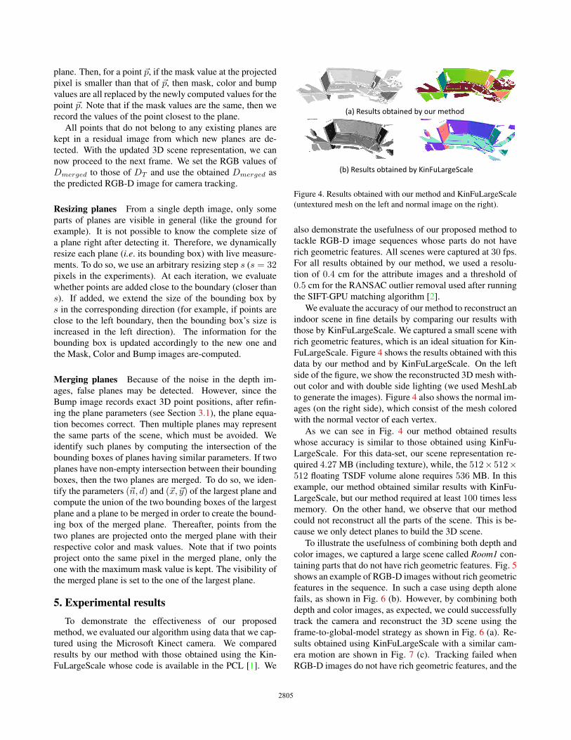
(a) Results obtained by our method
(b) Results obtained by KinFuLargeScale
Figure 4. Results obtained with our method and KinFuLargeScale
(untextured mesh on the left and normal image on the right).
also demonstrate the usefulness of our proposed method to
tackle RGB-D image sequences whose parts do not have
rich geometric features. All scenes were captured at 30 fps.
For all results obtained by our method, we used a resolu-
tion of 0.4 cm for the attribute images and a threshold of
0.5 cm for the RANSAC outlier removal used after running
the SIFT-GPU matching algorithm [2].
We evaluate the accuracy of our method to reconstruct an
indoor scene in fine details by comparing our results with
those by KinFuLargeScale. We captured a small scene with
rich geometric features, which is an ideal situation for Kin-
FuLargeScale. Figure 4 shows the results obtained with this
data by our method and by KinFuLargeScale. On the left
side of the figure, we show the reconstructed 3D mesh with-
out color and with double side lighting (we used MeshLab
to generate the images). Figure 4 also shows the normal im-
ages (on the right side), which consist of the mesh colored
with the normal vector of each vertex.
As we can see in Fig. 4 our method obtained results
whose accuracy is similar to those obtained using KinFu-
LargeScale. For this data-set, our scene representation re-
quired 4.27 MB (including texture), while, the 512× 512×512 floating TSDF volume alone requires 536 MB. In this
example, our method obtained similar results with KinFu-
LargeScale, but our method required at least 100 times less
memory. On the other hand, we observe that our method
could not reconstruct all the parts of the scene. This is be-
cause we only detect planes to build the 3D scene.
To illustrate the usefulness of combining both depth and
color images, we captured a large scene called Room1 con-
taining parts that do not have rich geometric features. Fig. 5
shows an example of RGB-D images without rich geometric
features in the sequence. In such a case using depth alone
fails, as shown in Fig. 6 (b). However, by combining both
depth and color images, as expected, we could successfully
track the camera and reconstruct the 3D scene using the
frame-to-global-model strategy as shown in Fig. 6 (a). Re-
sults obtained using KinFuLargeScale with a similar cam-
era motion are shown in Fig. 7 (c). Tracking failed when
RGB-D images do not have rich geometric features, and the
2805

RGB image Depth image
Figure 5. One input RGB-D image of the data-set Room1.
reconstruction stopped prematurely. The obtained recon-
structed scene with our method was of 1532 K vertices and
2423 K faces and our scene representation required 34 MB.
The RGB-D image sequence was processed at 2.4 fps in av-
erage when using SIFT for camera tracking, and at 7.3 fps
in average when using depth only.
Results obtained with another scene called Room2 are
shown in Fig. 7 (b), (d) and in Fig. 8. In this experiment, we
illustrate one interesting output of our scene representation.
That is, more than 3D meshes, our method directly outputs
roughly segmented 3D meshes. Therefore, we can easily
remove some parts of the reconstructed scene directly after
reconstruction; this enriches possible usage of our method
as seen below. The example shown in Fig. 8 was obtained
by simply hiding mesh layers in MeshLab. As we can see it
becomes easy to remove undesired objects from the recon-
structed scene (see Fig. 8 (d)), or on the contrary to keep
only objects of interest (see Fig. 8 (c)). We remark that,
like data Room1, KinFuLargeScale failed to reconstruct the
scene as parts of the sequence did not have rich geometric
features. Note that with the Room2 data we observed that
about 10% of points were missing because of non-planarity.
A possible usage of our scene representation is for the
operation of cleaning or repairing the reconstructing scene.
By using standard 2D painting softwares such as Photoshop,
it is easy to edit the Bump, Mask and Color images of differ-
ent planes that compose the scene. For example, the ground
(b) Results by our method without using color
(a) Results by our method when using color
Figure 6. Results obtained with our method for the data-set Room1with and without using color for the camera motion tracking.
(c) Data Room1 (d) Data Room2
Results obtained by our method
Results obtained by KinFuLargeScale
(a) Data Room1 (b) Data Room2
Figure 7. Results obtained by our method and KinFuLargeScale.
(a) The reconstructed scene
(c) The reconstructed table (d) The scene without the table
(b) The normal image
Figure 8. Results obtained with our method for the data-set Room2.
always contains holes because objects lying on it hide some
parts. By simply in-painting the Bump, Color and Mask
images, it is possible, in a post-process to fill the holes and
obtain a complete mesh for the ground. In the same manner,
it is also possible to remove outliers by putting their mask
value to 0.
Figure 9 shows an example where parts of the sequence
have neither geometric nor color features. As we can see
in Fig. 9 (a), the reconstruction failed when reconstructing
the scene as it is. But, as shown in Fig. 9 (b), by putting
a few boxes on the ground we could successfully track the
camera and obtain a correct reconstruction with the addi-
tional objects. Note that both image sequences were cap-
tured along similar path (i.e. parts of the image sequences
2806
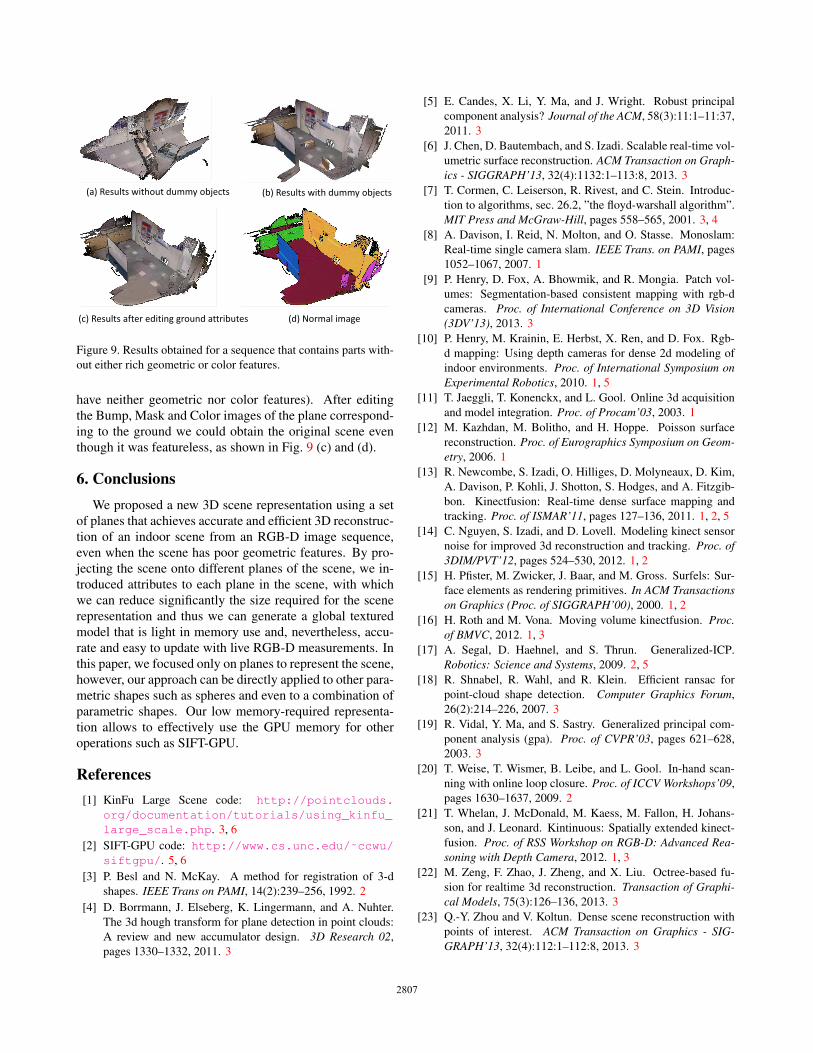
(a) Results without dummy objects (b) Results with dummy objects
(c) Results after editing ground attributes (d) Normal image
Figure 9. Results obtained for a sequence that contains parts with-
out either rich geometric or color features.
have neither geometric nor color features). After editing
the Bump, Mask and Color images of the plane correspond-
ing to the ground we could obtain the original scene even
though it was featureless, as shown in Fig. 9 (c) and (d).
6. ConclusionsWe proposed a new 3D scene representation using a set
of planes that achieves accurate and efficient 3D reconstruc-
tion of an indoor scene from an RGB-D image sequence,
even when the scene has poor geometric features. By pro-
jecting the scene onto different planes of the scene, we in-
troduced attributes to each plane in the scene, with which
we can reduce significantly the size required for the scene
representation and thus we can generate a global textured
model that is light in memory use and, nevertheless, accu-
rate and easy to update with live RGB-D measurements. In
this paper, we focused only on planes to represent the scene,
however, our approach can be directly applied to other para-
metric shapes such as spheres and even to a combination of
parametric shapes. Our low memory-required representa-
tion allows to effectively use the GPU memory for other
operations such as SIFT-GPU.
References[1] KinFu Large Scene code: http://pointclouds.
org/documentation/tutorials/using_kinfu_large_scale.php. 3, 6
[2] SIFT-GPU code: http://www.cs.unc.edu/˜ccwu/siftgpu/. 5, 6
[3] P. Besl and N. McKay. A method for registration of 3-d
shapes. IEEE Trans on PAMI, 14(2):239–256, 1992. 2
[4] D. Borrmann, J. Elseberg, K. Lingermann, and A. Nuhter.
The 3d hough transform for plane detection in point clouds:
A review and new accumulator design. 3D Research 02,
pages 1330–1332, 2011. 3
[5] E. Candes, X. Li, Y. Ma, and J. Wright. Robust principal
component analysis? Journal of the ACM, 58(3):11:1–11:37,
2011. 3
[6] J. Chen, D. Bautembach, and S. Izadi. Scalable real-time vol-
umetric surface reconstruction. ACM Transaction on Graph-ics - SIGGRAPH’13, 32(4):1132:1–113:8, 2013. 3
[7] T. Cormen, C. Leiserson, R. Rivest, and C. Stein. Introduc-
tion to algorithms, sec. 26.2, ”the floyd-warshall algorithm”.
MIT Press and McGraw-Hill, pages 558–565, 2001. 3, 4
[8] A. Davison, I. Reid, N. Molton, and O. Stasse. Monoslam:
Real-time single camera slam. IEEE Trans. on PAMI, pages
1052–1067, 2007. 1
[9] P. Henry, D. Fox, A. Bhowmik, and R. Mongia. Patch vol-
umes: Segmentation-based consistent mapping with rgb-d
cameras. Proc. of International Conference on 3D Vision(3DV’13), 2013. 3
[10] P. Henry, M. Krainin, E. Herbst, X. Ren, and D. Fox. Rgb-
d mapping: Using depth cameras for dense 2d modeling of
indoor environments. Proc. of International Symposium onExperimental Robotics, 2010. 1, 5
[11] T. Jaeggli, T. Konenckx, and L. Gool. Online 3d acquisition
and model integration. Proc. of Procam’03, 2003. 1
[12] M. Kazhdan, M. Bolitho, and H. Hoppe. Poisson surface
reconstruction. Proc. of Eurographics Symposium on Geom-etry, 2006. 1
[13] R. Newcombe, S. Izadi, O. Hilliges, D. Molyneaux, D. Kim,
A. Davison, P. Kohli, J. Shotton, S. Hodges, and A. Fitzgib-
bon. Kinectfusion: Real-time dense surface mapping and
tracking. Proc. of ISMAR’11, pages 127–136, 2011. 1, 2, 5
[14] C. Nguyen, S. Izadi, and D. Lovell. Modeling kinect sensor
noise for improved 3d reconstruction and tracking. Proc. of3DIM/PVT’12, pages 524–530, 2012. 1, 2
[15] H. Pfister, M. Zwicker, J. Baar, and M. Gross. Surfels: Sur-
face elements as rendering primitives. In ACM Transactionson Graphics (Proc. of SIGGRAPH’00), 2000. 1, 2
[16] H. Roth and M. Vona. Moving volume kinectfusion. Proc.of BMVC, 2012. 1, 3
[17] A. Segal, D. Haehnel, and S. Thrun. Generalized-ICP.
Robotics: Science and Systems, 2009. 2, 5
[18] R. Shnabel, R. Wahl, and R. Klein. Efficient ransac for
point-cloud shape detection. Computer Graphics Forum,
26(2):214–226, 2007. 3
[19] R. Vidal, Y. Ma, and S. Sastry. Generalized principal com-
ponent analysis (gpa). Proc. of CVPR’03, pages 621–628,
2003. 3
[20] T. Weise, T. Wismer, B. Leibe, and L. Gool. In-hand scan-
ning with online loop closure. Proc. of ICCV Workshops’09,
pages 1630–1637, 2009. 2
[21] T. Whelan, J. McDonald, M. Kaess, M. Fallon, H. Johans-
son, and J. Leonard. Kintinuous: Spatially extended kinect-
fusion. Proc. of RSS Workshop on RGB-D: Advanced Rea-soning with Depth Camera, 2012. 1, 3
[22] M. Zeng, F. Zhao, J. Zheng, and X. Liu. Octree-based fu-
sion for realtime 3d reconstruction. Transaction of Graphi-cal Models, 75(3):126–136, 2013. 3
[23] Q.-Y. Zhou and V. Koltun. Dense scene reconstruction with
points of interest. ACM Transaction on Graphics - SIG-GRAPH’13, 32(4):112:1–112:8, 2013. 3
2807


![Localizing 3D Cuboids in Single-view Images3dvision.princeton.edu/projects/2012/SUNprimitive/poster.pdf · 2013-04-23 · [2] Recognizing scene viewpoint using panoramic place representation](https://img.pdfslide.tips/doc/110x75/5f10e2117e708231d44b454d/localizing-3d-cuboids-in-single-view-2013-04-23-2-recognizing-scene-viewpoint.jpg)