Embed Size (px)
Citation preview
37th
International Electronic Manufacturing Technology Conference/18th
Electronics Materials and Packaging, 2016
A Polymer-made 3DOF Spatial Parallel Manipulator
for Cell Production System
Mikio HORIE
Tokyo Institute of Technology
4259-R2-14, Nagatsuta-cho, Midori-ku, Yokohama, 226-8503, Japan
E-email : [email protected] / mahorie767 @gmail.com, Phone : +81-45-924-5048 / +81-90-8003-8672
Abstract
In the present paper, in order to realize the functions
equivalent to the functions of the spherical bearing which is
frequently used in conventional spatial mechanisms, a
polymeric manufactured hinge with Hytrel® (DUPONT Co.,
Ltd.)[1], which has excellent flexural fatigue resistance, have
been proposed. Next, the shape and dimensions of the
polymeric manufactured hinge having low stress values at
bending deformation have been found by FEM analysis
results. In addition, a polymer-made three-degrees-of-
freedom(3DOF) spatial parallel manipulator which consists
of this polymer-made hinge is designed and developed, and
the output displacement characteristics of the manipulator
are revealed.
1. Introduction
In the Horie laboratory, the rotation bearing was replaced
with a polymer material, and a polymer-made revolute hinge
(R hinge) was proposed. Next, design and development of a
polymer-made two-degrees-of-freedom pantograph mech.
and a polymer-made three-degrees-of-freedom planar
parallel manipulator which consists of R hinges was carried
out, and their characteristics were revealed [2]~[4]. In this
paper, for the small and high precision positioning table in
the cell production system, which is used a camera company
and/or small-size and high precision machines or machine
elements, polymer-made spherical hinges which can
represent three degrees-of-freedom (3DOF) as spherical
bearings are proposed. Then, in order to design and
manufacture polymer-made spatial mech. consisting of
polymer-made spherical hinges, the shape and dimension of
the polymer-made spherical hinges are discussed, and
characteristics of 3DOF spatial parallel manipulator which
consists of S hinges are revealed.
2. Polymer–made Spherical Hinges
In this chapter, a polymer-made spherical hinge (S
Hinge) is proposed and its bending characteristics are
discussed.
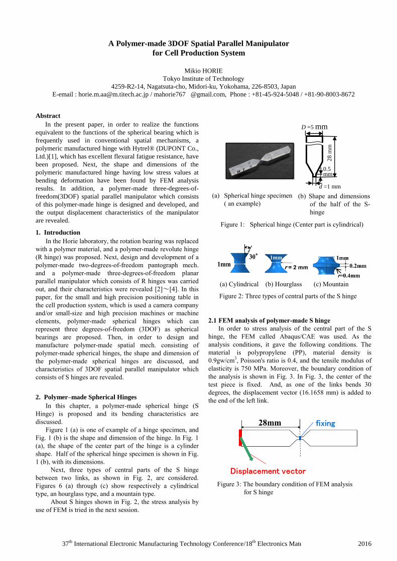
Figure 1 (a) is one of example of a hinge specimen, and
Fig. 1 (b) is the shape and dimension of the hinge. In Fig. 1
(a), the shape of the center part of the hinge is a cylinder
shape. Half of the spherical hinge specimen is shown in Fig.
1 (b), with its dimensions.
Next, three types of central parts of the S hinge
between two links, as shown in Fig. 2, are considered.
Figures 6 (a) through (c) show respectively a cylindrical
type, an hourglass type, and a mountain type.
About S hinges shown in Fig. 2, the stress analysis by
use of FEM is tried in the next session.
2.1 FEM analysis of polymer-made S hinge
In order to stress analysis of the central part of the S
hinge, the FEM called Abaqus/CAE was used. As the
analysis conditions, it gave the following conditions. The
material is polypropylene (PP), material density is
0.9gw/cm3, Poisson's ratio is 0.4, and the tensile modulus of
elasticity is 750 MPa. Moreover, the boundary condition of
the analysis is shown in Fig. 3. In Fig. 3, the center of the
test piece is fixed. And, as one of the links bends 30
degrees, the displacement vector (16.1658 mm) is added to
the end of the left link.
Figure 1: Spherical hinge (Center part is cylindrical)
(a) Spherical hinge specimen
( an example) (b) Shape and dimensions
of the half of the S-
hinge
D =5 mm
0.5 mm
d =1 mm
28
mm
Figure 3: The boundary condition of FEM analysis
for S hinge
(a) Cylindrical (b) Hourglass (c) Mountain
Figure 2: Three types of central parts of the S hinge
37th
International Electronic Manufacturing Technology Conference/18th
Electronics Materials and Packaging, 2016
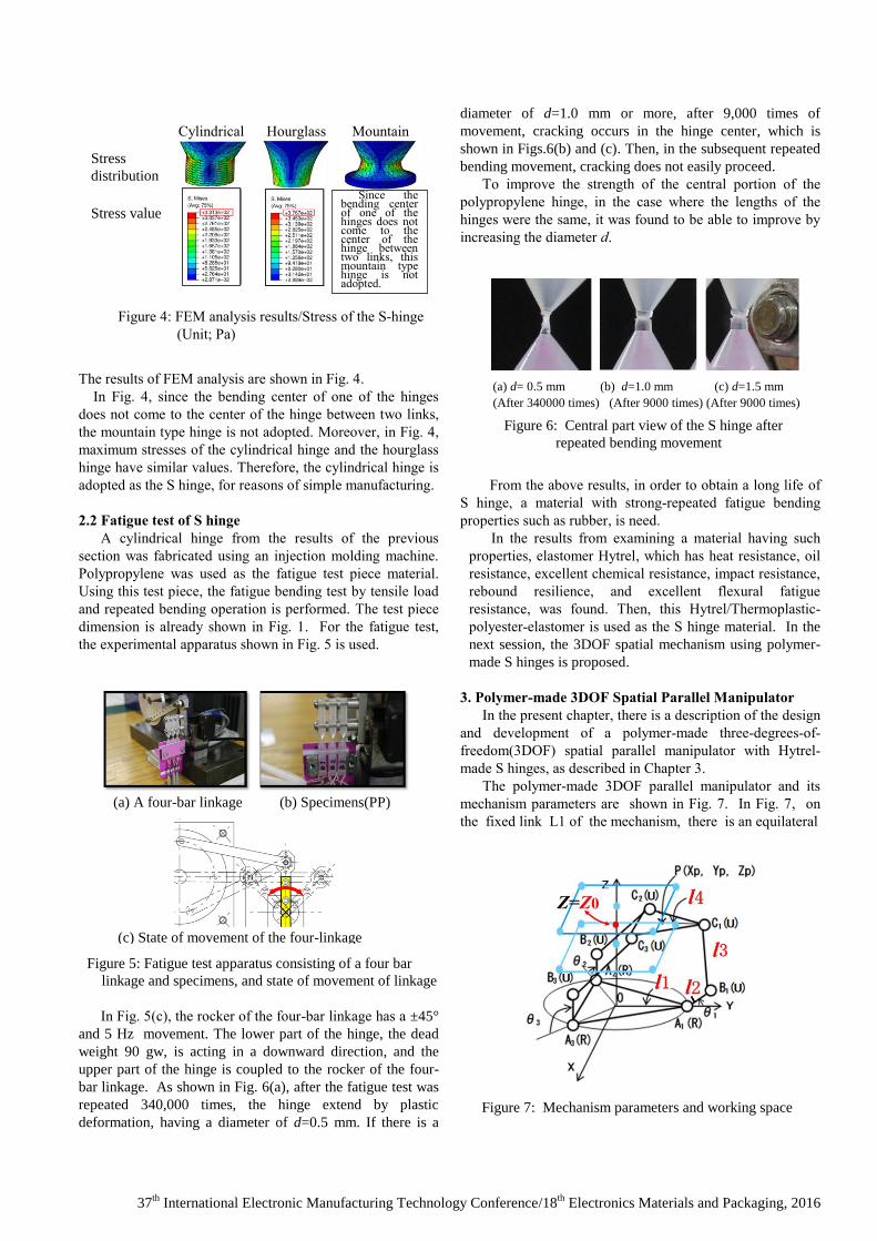
The results of FEM analysis are shown in Fig. 4.
In Fig. 4, since the bending center of one of the hinges
does not come to the center of the hinge between two links,
the mountain type hinge is not adopted. Moreover, in Fig. 4,
maximum stresses of the cylindrical hinge and the hourglass
hinge have similar values. Therefore, the cylindrical hinge is
adopted as the S hinge, for reasons of simple manufacturing.
2.2 Fatigue test of S hinge
A cylindrical hinge from the results of the previous
section was fabricated using an injection molding machine.
Polypropylene was used as the fatigue test piece material.
Using this test piece, the fatigue bending test by tensile load
and repeated bending operation is performed. The test piece
dimension is already shown in Fig. 1. For the fatigue test,
the experimental apparatus shown in Fig. 5 is used.
In Fig. 5(c), the rocker of the four-bar linkage has a ±45°
and 5 Hz movement. The lower part of the hinge, the dead
weight 90 gw, is acting in a downward direction, and the
upper part of the hinge is coupled to the rocker of the four-
bar linkage. As shown in Fig. 6(a), after the fatigue test was
repeated 340,000 times, the hinge extend by plastic
deformation, having a diameter of d=0.5 mm. If there is a
diameter of d=1.0 mm or more, after 9,000 times of
movement, cracking occurs in the hinge center, which is
shown in Figs.6(b) and (c). Then, in the subsequent repeated
bending movement, cracking does not easily proceed.
To improve the strength of the central portion of the
polypropylene hinge, in the case where the lengths of the
hinges were the same, it was found to be able to improve by
increasing the diameter d.
From the above results, in order to obtain a long life of
S hinge, a material with strong-repeated fatigue bending
properties such as rubber, is need.
In the results from examining a material having such
properties, elastomer Hytrel, which has heat resistance, oil
resistance, excellent chemical resistance, impact resistance,
rebound resilience, and excellent flexural fatigue
resistance, was found. Then, this Hytrel/Thermoplastic-
polyester-elastomer is used as the S hinge material. In the
next session, the 3DOF spatial mechanism using polymer-
made S hinges is proposed.
3. Polymer-made 3DOF Spatial Parallel Manipulator
In the present chapter, there is a description of the design
and development of a polymer-made three-degrees-of-
freedom(3DOF) spatial parallel manipulator with Hytrel-
made S hinges, as described in Chapter 3.
The polymer-made 3DOF parallel manipulator and its
mechanism parameters are shown in Fig. 7. In Fig. 7, on
the fixed link L1 of the mechanism, there is an equilateral
Figure 6: Central part view of the S hinge after
repeated bending movement
(a) d= 0.5 mm (b) d=1.0 mm (c) d=1.5 mm
(After 340000 times) (After 9000 times) (After 9000 times)
Figure 7: Mechanism parameters and working space
Figure 4: FEM analysis results/Stress of the S-hinge
(Unit; Pa)
Cylindrical Hourglass Mountain
Stress
distribution
Stress value
Since the bending center of one of the hinges does not come to the center of the hinge between two links, this mountain type hinge is not adopted.
Figure 5: Fatigue test apparatus consisting of a four bar
linkage and specimens, and state of movement of linkage
(a) A four-bar linkage (b) Specimens(PP)
(c) State of movement of the four-linkage
37th
International Electronic Manufacturing Technology Conference/18th
Electronics Materials and Packaging, 2016
triangle. The center of the equilateral triangle is the origin O
of the orthogonal coordinate system O-XYZ. The distance
from its center of gravity (center) until the three rotary
actuators position Aj (j = 1 ~ 3) is l1. The length of the
input links L2j (j = 1 ~ 3) is l2, the length of the intermediate
link/coupler L3j (j = 1 ~ 3) is l3, the distance between the
center of gravity of the equilateral triangle on the output link
L4 and the joint position Cj on L3 is l4, and the initial
position of the center point P of the output link L4 in the Z-
axis is Z = Z0.
The squares in Fig. 7 show the loci of the center point P
of the equilateral triangle, which is the output link of the
manipulator, and represents the limits of the working space
of the mechanism when Z= ±25 mm. The length of one side
of the square is 100 mm. The square center, which is the
initial position of the output point P, is on the Z-axis.
3.1 Mechanism synthesis
In order to synthesize the mechanism, at the position Z =
Z0 mm and Z = Z0±25 mm, the mechanism parameters l1, l2,
l3, l4, and the value of the Z0, each varied by 1mm, were
determined by considering the following conditions.
(1) As the point P passes through the square of the four
corners point and the square center point, i.e., 10 points on
the square in Fig. 7, mechanism parameters were determined
by using inverse kinematics
[5],[6]. Among the results
obtained, only the mechanism parameters having three input
angles determined by the equation of inverse kinematics
were the correct solution.
(2) Reduce the size for miniaturization.
(3) The relative angular displacement of the two links across
the hinge portion is in the range of ±45°.
(4) In order to reduce the driving torque of the motor, the
ratio of the length of the links L2 and L3, that is, L2/L3 to
0.6 [7].
3.2 Mechanism parameters and discussion
In the results of the mechanisms synthesis described, in
the previous session, mechanism parameters are obtained, as
shown in Table 1. By use of these parameters, the 3DOF
spatial parallel manipulator is manufactured. Next, in order
to consider the relative displacement angles between L2 and
L3, L3, and L4 at the S hinge positions, the displacement
analysis was carried out. Table 2 shows the analytical results
about pitch angles and yaw angles at joints Bj and Cj (j = 1 ~
3).
From Table 2, it is revealed that the relative
displacement angles are within ±45°.
l1 l2 l3 l4 Z0
mm 35 60 100 27.5 97
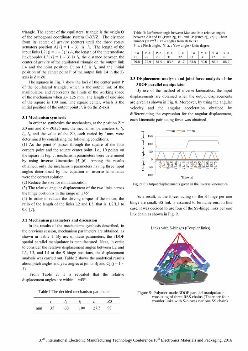
3.3 Displacement analysis and joint force analysis of the
3DOF parallel manipulator
By use of the method of inverse kinematics, the input
displacements are obtained when the output displacements
are given as shown in Fig. 8. Moreover, by using the angular
velocity and the angular acceleration obtained by
differentiating the expression for the angular displacement,
each kinematic pair acting force was obtained.
As a result, as the forces acting on the S hinge per one
hinge are small, SS link is assumed to be numerous. In this
case, it was decided to use four of the SS-hinge links per one
link chain as shown in Fig. 9.
Table I The decided mechanism-parameter
Table II: Difference angle between Max and Min relative angles
between AB and BC(Pitch 2j), BC and CP (Pitch 3j), / sj: j-Chain
number (j=1~3), Yaw angles from Bi to Ci /
P. a. : Pitch angle, Y. a. : Yaw angle / Unit; degree
P. a.
21
P. a.
22
P. a.
23
P. a.
31
P. a.
32
P. a.
33
Y. a
s1
Y. a
s2
Y. a
s3
79.8 72.9 81.9 83.8 81.7 83.8 60.0 86.2 86.2
Figure 8: Output displacements given in the inverse kinematics
Figure 9: Polymer-made 3DOF parallel manipulator consisting of three RSS chains (There are four coupler links with S-hinges per one SS chain)
Links with S-hinges (Coupler links)
37th
International Electronic Manufacturing Technology Conference/18th
Electronics Materials and Packaging, 2016
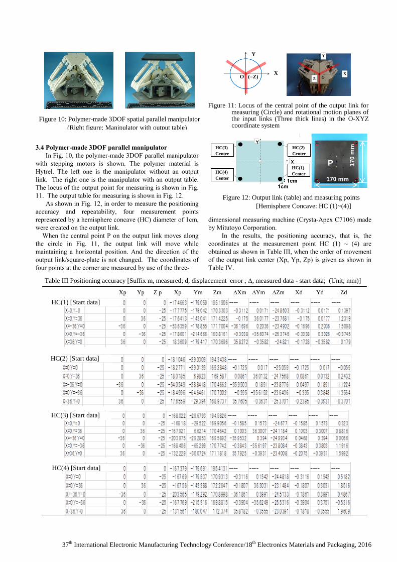
3.4 Polymer-made 3DOF parallel manipulator
In Fig. 10, the polymer-made 3DOF parallel manipulator
with stepping motors is shown. The polymer material is
Hytrel. The left one is the manipulator without an output
link. The right one is the manipulator with an output table.
The locus of the output point for measuring is shown in Fig.
11. The output table for measuring is shown in Fig. 12.
As shown in Fig. 12, in order to measure the positioning
accuracy and repeatability, four measurement points
represented by a hemisphere concave (HC) diameter of 1cm,
were created on the output link.
When the central point P on the output link moves along
the circle in Fig. 11, the output link will move while
maintaining a horizontal position. And the direction of the
output link/square-plate is not changed. The coordinates of
four points at the corner are measured by use of the three-
dimensional measuring machine (Crysta-Apex C7106) made
by Mitutoyo Corporation.
In the results, the positioning accuracy, that is, the
coordinates at the measurement point HC (1) ~ (4) are
obtained as shown in Table III, when the order of movement
of the output link center (Xp, Yp, Zp) is given as shown in
Table IV.
Figure 10: Polymer-made 3DOF spatial parallel manipulator
(Right figure: Manipulator with output table)
Y
X O (=Z)
Figure 11: Locus of the central point of the output link for measuring (Circle) and rotational motion planes of the input links (Three thick lines) in the O-XYZ coordinate system
Figure 12: Output link (table) and measuring points
[Hemisphere Concave: HC (1)~(4)]
17
0 m
m
P
170 mm
HC(2)
Center
HC(1)
Center
HC(3)
Center
HC(4)
Center
Table III Positioning accuracy [Suffix m, measured; d, displacement error, measured data - start data; (Unit; mm)]
)
Xp Yp Z p Xp Ym Zm Xm Ym Zm Xd Yd Zd
HC(2) [Start data]
HC(3) [Start data]
HC(4) [Start data]
HC(1) [Start data]

37th
International Electronic Manufacturing Technology Conference/18th
Electronics Materials and Packaging, 2016
Moreover, the repeatability is obtained, as shown in
Table V.
From Table III, the positioning accuracy in the Z-axis
direction is about 1.96 mm at maximum in the working space
100*100 mm. This value may be possible to improve, by
local possibilities of further reducing the diameter of the
hinge. And, from Z in Table V, the reproducibility is found
to be about 0.082*2=0.16 mm at maximum.
4. Conclusion
In the present study, polymer-made planar hinge and
polymer-made spherical/S hinge are discussed. Especially,
shape and dimensions of polymer-made S hinges made by a
"Thermoplastic polyester elastomer” called Hytrel were
discussed. The Hytrel was found to be a good material for
the S hinge. Then, polymer-made three degrees-of-freedom
(3DOF) spatial parallel manipulator, which obtained a
mechanism synthesis were designed and manufactured by
use of the Hytrel. The positioning accuracy and repeatability
positioning accuracy of this parallel manipulator was
revealed.
Acknowledgments
I would like to thank Mr. Misao Kobayashi, Mr.
Takehiko Saito and Mr. Naoto Mochizuki of NISCA
CORPORATION which is a partner of the joint research,
and to thank Mr. Issei Unezawa who is a graduate school
student of Tokyo Institute of Technolohy.
References
1. DUPONT Co., Ltd.;
http://www.tdnet.co.jp/hytrel/about/index.html
2. Horie M, et al. (1997) Design System of Super Elastic
Hinges and its Application to Micromanipulators,
JSME International Journal,Ser. C, Vol.40, [No.2] pp.
323~328.
3. Horie M, et al. (2006) Durability of Large-Deflective
Hinges made of Blend Polypropylene used for Molded
Pantograph Mechanisms, ROMANSY 16, ROBOT
DESIGN, DYNAMICS, AND CONTROL, pp.355-362.
4. Horie M, et al. (2002) 3-DOF Planar Positioning-
Orientation Mechanisms with Links and Large-
Deflective Hinges, ROMANSY 14, Theory and Practice
of Robots and Manipulators, p.351-358.
5. Laribi1 M.A., et al. (2008) Advanced Synthesis of the
DELTA Parallel Robot for a Specified Workspace,
Parallel Manipulators, towards New Applications, I-Tech
Education and Publishing, ISBN: 978-3-902613-40-0, pp.
207-224. April.
6. Lo´pez M, et al. (2006) Delta robot: inverse, direct, and
intermediate Jacobians, Proc. IMechE Vol. 220 Part C: J.
Mechanical Engineering Science.
7. Arai T, et al. (2012) Design of delta arm driven by linear
actuator based on the kinetics. The 30-th Annual
Conference of the RSJ, 2O1-6(in Japanese).
Measuring
order Xp Yp Zp
1 0 0 -25
2 0 36 -25
3 -36 0 -25
4 0 -36 -25
5 36 0 -25
6 0 0 25
7 0 36 25
8 -36 0 25
9 0 -36 25
10 36 0 25
Table IV: The order of movement of the output
link center (Xp, Yp, Zp); mm
Table V Repeatability; mm
(1)
(2)
(3)
(4)
(1)
(2)
(3)
(4)
(1)
(2)
(3)
(4)
XYZ
XYZ
XYZ
HC(1) HC(2) HC(3) HC(4)
HC(1) HC(2) HC(3) HC(4)
HC(1) HC(2) HC(3) HC(4)
X Y Z
X Y Z
X Y Z