Embed Size (px)
Citation preview

8/3/2019 AC UserGuide 2011 en Metric
http://slidepdf.com/reader/full/ac-userguide-2011-en-metric 1/114

8/3/2019 AC UserGuide 2011 en Metric
http://slidepdf.com/reader/full/ac-userguide-2011-en-metric 2/114
This document has been carefully prepared with all the informationneeded to properly use this Advance product.
This document contains a brief description of the software functions andis not a replacement for the training program. This guide includesinformation about all the modules, including those that are optional.
In case of any discrepancy between the information given in this guideand the software, the software is the most up to date source.
The content of this guide can be modified without notice. Any
reproduction or distribution, even in partial, by any means - electronicallyor mechanically - of the contents of the present guide and other supplieddocumentation is strictly forbidden without GRAITEC's explicitauthorization.
Windows XP ®
and Windows Vista ®
are trademarks or registeredtrademarks of the Microsoft Corporation.
DXFTM
, DWGTM
, AutoCAD ®
and Autodesk Architectural Desktop ®
aretrademarks or registered trademarks of Autodesk Inc. San Rafael, CA.
All the other marks belong to their owners.
8/3/2019 AC UserGuide 2011 en Metric
http://slidepdf.com/reader/full/ac-userguide-2011-en-metric 3/114

8/3/2019 AC UserGuide 2011 en Metric
http://slidepdf.com/reader/full/ac-userguide-2011-en-metric 4/114
Views Toolbar ................................................................................................................................................ 38 Reinforcement Symbols toolbar .................................................................................................................... 40 Documents toolbar ........................................................................................................................................ 40 Tools toolbar .................................................................................................................................................. 41 Bar Editor toolbar ........................................................................................................................................... 41 Automatic Drafting toolbar ............................................................................................................................. 41 Graitec Transfer Center toolbar ..................................................................................................................... 42 Import-Export standard files toolbar .............................................................................................................. 42 Help Toolbar .................................................................................................................................................. 42
ADVANCE MENUS................................................................................................................................................. 43 Main menu ..................................................................................................................................................... 43 Context menus .............................................................................................................................................. 44 Shortcut Access Menu ................................................................................................................................... 44
UTILITIES ............................................................................................................................................................ 45 AutoUCS ........................................................................................................................................................ 45
LAYER MANAGER ................................................................................................................................................. 45 Layer Name manager .................................................................................................................................... 46 Tooltips .......................................................................................................................................................... 46 Material Manager ........................................................................................................................................... 46 Object Geometry Manager ............................................................................................................................ 47 Representation Styles Manager .................................................................................................................... 47 Doors and Windows manager ....................................................................................................................... 48 Bars and Meshes manager ........................................................................................................................... 48 Multicriteria object selection .......................................................................................................................... 49 Displaying objects by type ............................................................................................................................. 49 Automatic Reinforcement Objects ................................................................................................................. 49 Viewer 3D ...................................................................................................................................................... 50
CHAPTER 3 USING ADVANCE ......................................................................................................................... 51 ADVANCE BY EXAMPLES ....................................................................................................................................... 52
Formwork and Implementation ...................................................................................................................... 52 Reinforcement ............................................................................................................................................... 52
FORMWORK AND IMPLEMENTATION ....................................................................................................................... 53 Basic settings ................................................................................................................................................ 53 CONSTRUCT A MODEL .......................................................................................................................................... 54
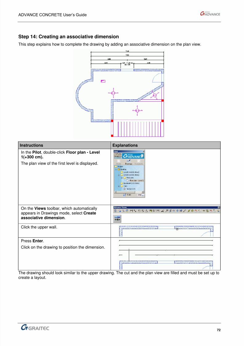
Step 1: Create continuous walls .................................................................................................................... 54 Step 2: Draw a straight wall and a curved wall.............................................................................................. 55 Step 3: Adjust the walls ................................................................................................................................. 56 Step 4: Creating columns .............................................................................................................................. 57 Step 5: Create the beams and slabs ............................................................................................................. 58 Step 6: Create a door and a window ............................................................................................................. 60 Step 7: Use the AutoUCS tool to position a slab hole ................................................................................... 61 Step 8: Automatically create the second level............................................................................................... 62 Step 9: Generate foundations ....................................................................................................................... 63 Step 10: Use the "roof" function to raise a slab ............................................................................................. 64 Step 11: Creating stairs ................................................................................................................................. 66 CREATE DRAWINGS ............................................................................................................................................. 69 Step 12: Creating a cut .................................................................................................................................. 69 Step 13: Create a plan view .......................................................................................................................... 71 Step 14: Creating an associative dimension ................................................................................................. 72
CREATE A LAYOUT ............................................................................................................................................... 73 Step 15: Create an A4 layout ........................................................................................................................ 73
EXPORT THE MODEL FOR CALCULATIONS .............................................................................................................. 75 Step 16: Export the model to Arche Building structure ................................................................................. 75
REINFORCEMENT................................................................................................................................................. 76 Create reinforcement drawings ..................................................................................................................... 76 Step 1: Create the reinforcement drawing of a wall ...................................................................................... 76
TRANSVERSAL REINFORCEMENT PLACEMENT ........................................................................................................ 79 Step 2: Define and place the transversal reinforcement around a window opening ..................................... 79 LONGITUDINAL REINFORCEMENT PLACEMENT ........................................................................................................ 86 Step 3: Define and distribute the longitudinal reinforcement around the window opening .................................... 86 Step 4: View the reinforcement in 3D ............................................................................................................ 90
PLACE REFERENCE MARKS ON THE DISTRIBUTION BARS ......................................................................................... 92
8/3/2019 AC UserGuide 2011 en Metric
http://slidepdf.com/reader/full/ac-userguide-2011-en-metric 5/114
Step 5: Place reference marks and dimensions on the distribution bars. ...................................................... 92 PLACE A BAR LIST ................................................................................................................................................. 95
Step 6: Place the list with bar bending details ................................................................................................ 95 PLACE THE MESHES.............................................................................................................................................. 96
Step 7: Place meshes on the wall sides ......................................................................................................... 96 PLACE A MESH LIST............................................................................................................................................... 98
Step 8: Place the mesh list ............................................................................................................................. 98 APPENDICES COMMAND LINE .......................................................................................................................... 99
ADVANCE COMMANDS......................................................................................................................................... 100 Getting help .................................................................................................................................................. 100 Managing the projects .................................................................................................................................. 100 Modeling a building....................................................................................................................................... 101 Modeling a level ............................................................................................................................................ 101 Creating the formwork .................................................................................................................................. 101 Creating the reinforcement ........................................................................................................................... 102 Creating and managing model drawings ...................................................................................................... 103 Dimensioning the drawings and views ......................................................................................................... 104 Adding symbols and annotations ................................................................................................................. 104 Creating and using the lists .......................................................................................................................... 105 Creating layouts ............................................................................................................................................ 105 Using Utilities ................................................................................................................................................ 105 Using Internet services ................................................................................................................................. 106
INDEX .................................................................................................................................................................. 107

8/3/2019 AC UserGuide 2011 en Metric
http://slidepdf.com/reader/full/ac-userguide-2011-en-metric 6/114

8/3/2019 AC UserGuide 2011 en Metric
http://slidepdf.com/reader/full/ac-userguide-2011-en-metric 7/114
Welcome
In this Chapter
Welcome to GRAITEC Advance,
Perfectly integrated with AutoCAD®, Advance accelerates thecreation of reinforced concrete and steel structures with toolsdedicated to modeling and accelerates document creationrequired for the construction process: general arrangementdrawings, detailing, manufacturing drawings, lists, BOM's, etc.
GRAITEC Advance includes:
– Advance Steel for creating structural steel arrangementdrawings, shop drawings, lists and NC files.
– Advance Concrete for creating reinforcement and structuralconcrete drawings
– Advance Design for the analysis and design of
reinforcement concrete and steel structures and automatedcreation of design reports.
Advance is part of the GRAITEC CAD / Analysis and Designsuite and therefore directly connects to other GRAITECengineering solutions.
This user guide, dedicated to the Concrete suite, allows you toget quickly and simply a set of main functionalities and to exploitthe Advance work methodology. For a quick start, refer to thetutorial in Chapter 3 Using Advance.
All software tools described in this guide and all remarks related
to the product pertain only to the Advance Concrete and for reading simplification only the generic name Advance is used.
■ Introduction
■ How to use this guide ?
■ Where to find information ■ Contacting technical support
■ Log on to GRAITEC Advantages Web site
8/3/2019 AC UserGuide 2011 en Metric
http://slidepdf.com/reader/full/ac-userguide-2011-en-metric 8/114
ADVANCE CONCRETE User’s Guide
8
Introduction
Advance Concrete is the essential AutoCAD® extension for modeling and for automated construction andreinforcement drawing creation.
With intelligent Advance objects, a three dimensional model is created and stored in a drawing. Once the modelis complete, Advance creates all structural and reinforcement drawings using a large selection of viewproduction tools, dimensions, locations, symbols and automatic layout functions.
Advance is completely integrated in AutoCAD® making it easy and intuitive to learn. Advance uses the latestAutoCAD® ObjectARX® technology. This advanced technology provides users with professional objects (e.g.,beams, columns, and bars) perfectly integrated into AutoCAD® on which most standard functions (e.g., copy,paste, extend, trim, stretch, etc.) can be applied.
The use of the ObjectARX® technology allows Advance to provide you professional tools combining the powerof AutoCAD® or Autodesk Architectural Desktop® design & GRAITEC's experience in the field of structuralmodeling. Indeed, Advance is completely compatible with the structural calculation software proposed byGRAITEC.
The objective of this user guide is to train you in no time and to provide guidelines on installing and using thesoftware along with suggestions for improving work efficiency and productivity.
This guide also contains information on Advance’s user interface and a tutorial on the main software featuresand concepts.

8/3/2019 AC UserGuide 2011 en Metric
http://slidepdf.com/reader/full/ac-userguide-2011-en-metric 9/114
ADVANCE CONCRETE User’s Guide
9
How to use this guide ?
This guide includes:
The steps involved in installing the software and obtaining a license (Chapter 1: Installing Advance)A description of Advance’s user interface and functions (Chapter 2: Discovering Advance)
A tutorial on using Advance (Chapter 3: Using Advance)
Spend some time for reading this guide and it will help you to take your first steps with Advance.
All Advance commands are listed in the Appendix.
An index is available at the end of the guide.
For mode information, contact your dealer or visit GRAITEC’s website (www.graitec.com).
8/3/2019 AC UserGuide 2011 en Metric
http://slidepdf.com/reader/full/ac-userguide-2011-en-metric 10/114
ADVANCE CONCRETE User’s Guide
10
Where to find information in Advance Concrete
Accessing the online help
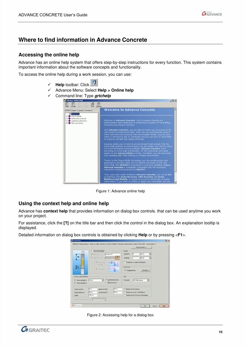
Advance has an online help system that offers step-by-step instructions for every function. This system containsimportant information about the software concepts and functionality.
To access the online help during a work session, you can use:
Help toolbar: Click
Advance Menu: Select Help > Online help
Command line: Type grtchelp
Figure 1: Advance online help
Using the context help and online help
Advance has context help that provides information on dialog box controls. that can be used anytime you workon your project.
For assistance, click the [?] on the title bar and then click the control in the dialog box. An explanation tooltip isdisplayed.
Detailed information on dialog box controls is obtained by clicking Help or by pressing <F1>.
Figure 2: Accessing help for a dialog box

8/3/2019 AC UserGuide 2011 en Metric
http://slidepdf.com/reader/full/ac-userguide-2011-en-metric 11/114
ADVANCE CONCRETE User’s Guide
11
Using Self-training: Advance Learning Program
The Advance Learning Program is an interactive self-training system that is installed with Advance. SinceAdvance works with AutoCAD® and Autodesk Architectural Desktop® basic tools, the Advance LearningProgram involves training of the methodologies used in these systems. The Advance Learning Programcontains step-by-step instructions for creating drawings and understanding Advance’s functions.
The advantage of using the Advance Learning Program is that the training is self-paced and focuses onspecific subjects.
To access the Advance Learning Program:
Help toolbar: Click
Advance Menu: Select Help > Advance Learning Program
Command line: Type grtcselftraining
Figure 3: Learning Program
.

8/3/2019 AC UserGuide 2011 en Metric
http://slidepdf.com/reader/full/ac-userguide-2011-en-metric 12/114

8/3/2019 AC UserGuide 2011 en Metric
http://slidepdf.com/reader/full/ac-userguide-2011-en-metric 13/114
Chapter 1Installing Advance
In this Chapter
■ Software configuration
■ Installing Advance
8/3/2019 AC UserGuide 2011 en Metric
http://slidepdf.com/reader/full/ac-userguide-2011-en-metric 14/114
ADVANCE CONCRETE User’s Guide
14
Configuration
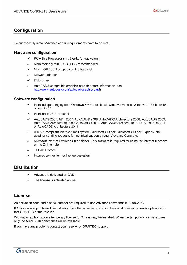
To successfully install Advance certain requirements have to be met.
Hardware configuration
PC with a Processor min. 2 GHz (or equivalent)
Main memory min. 2 GB (4 GB recommended)
Min. 1 GB free disk space on the hard disk
Network adapter
DVD Drive
AutoCAD® compatible graphics-card (for more information, seehttp://www.autodesk.com/autocad-graphicscard)
Software configuration
Installed operating system Windows XP Professional, Windows Vista or Windows 7 (32-bit or 64-bit version) \
Installed TCP/IP Protocol
AutoCAD® 2007, ADT 2007, AutoCAD® 2008, AutoCAD® Architecture 2008, AutoCAD® 2009,AutoCAD® Architecture 2009, AutoCAD® 2010, AutoCAD® Architecture 2010, AutoCAD® 2011or AutoCAD® Architecture 2011
A MAPI compliant Microsoft mail system (Microsoft Outlook, Microsoft Outlook Express, etc.)used for sending requests for technical support through Advance Concrete.
Microsoft Internet Explorer 4.0 or higher. This software is required for using the internet functionsor the Online help.
TCP/IP Protocol
Internet connection for license activation
Distribution
Advance is delivered on DVD.
The license is activated online.
License
An activation code and a serial number are required to use Advance commands in AutoCAD®.
If Advance was purchased, you already have the activation code and the serial number; otherwise please con-tact GRAITEC or the reseller.
Without an authorization a temporary license for 5 days may be installed. When the temporary license expires,only the AutoCAD® commands will be available.
If you have any problems contact your reseller or GRAITEC support.

8/3/2019 AC UserGuide 2011 en Metric
http://slidepdf.com/reader/full/ac-userguide-2011-en-metric 15/114
ADVANCE CONCRETE User’s Guide
15
Before installing Advance
Administrator rights are required to install Advance.
Installing Advance
AutoCAD® or Autodesk Architectural Desktop® must first be installed on the system prior to installing Advance.
Installation of AutoCAD® or Autodesk Architectural Desktop®
Follow the detailed instructions provided in the AutoCAD® or Autodesk Architectural Desktop documentation.
8/3/2019 AC UserGuide 2011 en Metric
http://slidepdf.com/reader/full/ac-userguide-2011-en-metric 16/114
ADVANCE CONCRETE User’s Guide
16
Advance installation
Proceed with the installation as follows:
1. Close all active WINDOWS applications.
2. Insert the installation DVD into the DVD drive.
The setup program starts automatically and the following dialog box appears.
1. Close all active WINDOWS applications.
2. Insert the installation DVD into the DVD drive.
The setup program starts automatically and the DVD Browser appears.
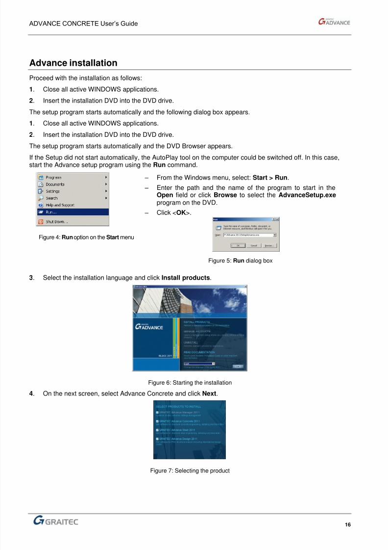
If the Setup did not start automatically, the AutoPlay tool on the computer could be switched off. In this case,start the Advance setup program using the Run command.
Figure 4: Runoption on the Start menu
– From the Windows menu, select: Start > Run.
– Enter the path and the name of the program to start in theOpen field or click Browse to select the AdvanceSetup.exe program on the DVD.
– Click <OK>.
Figure 5: Run dialog box
3. Select the installation language and click Install products.
Figure 6: Starting the installation4. On the next screen, select Advance Concrete and click Next.
Figure 7: Selecting the product
8/3/2019 AC UserGuide 2011 en Metric
http://slidepdf.com/reader/full/ac-userguide-2011-en-metric 17/114
ADVANCE CONCRETE User’s Guide
17
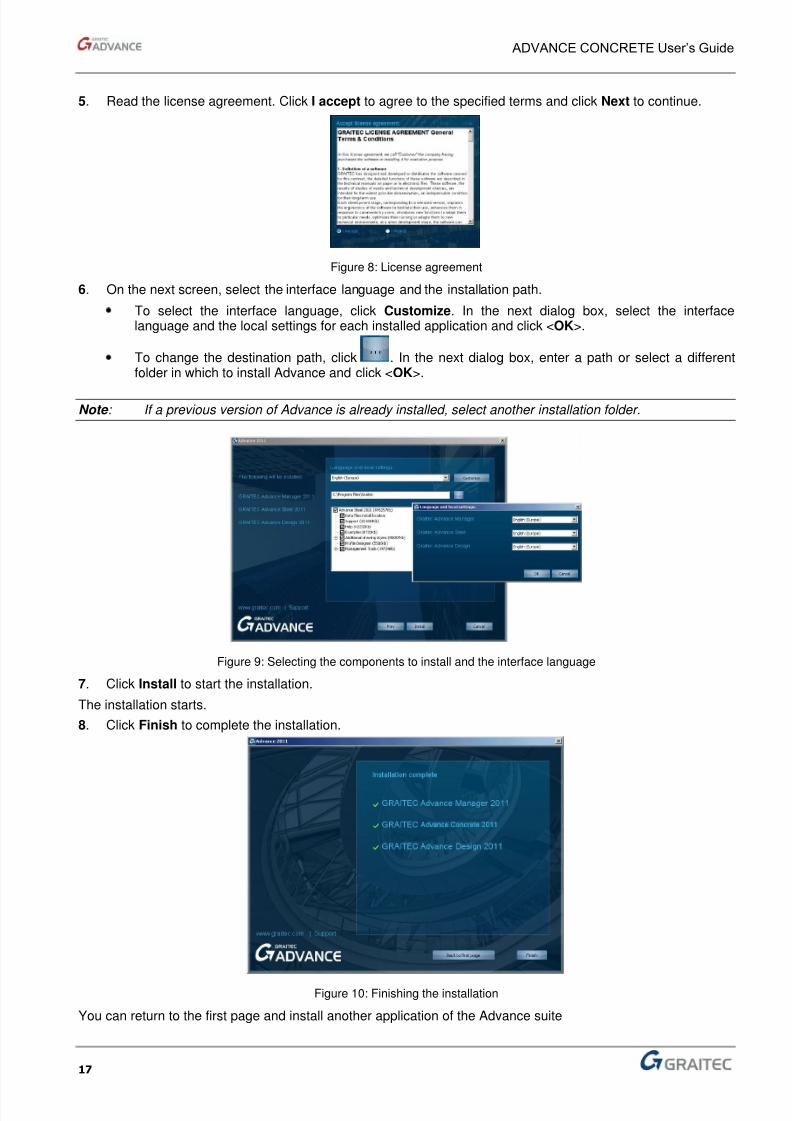
5. Read the license agreement. Click I accept to agree to the specified terms and click Next to continue.
Figure 8: License agreement
6. On the next screen, select the interface language and the installation path.
To select the interface language, click Customize. In the next dialog box, select the interfacelanguage and the local settings for each installed application and click <OK>.
To change the destination path, click . In the next dialog box, enter a path or select a differentfolder in which to install Advance and click <OK>.
Note : If a previous version of Advance is already installed, select another installation folder.
Figure 9: Selecting the components to install and the interface language
7. Click Install to start the installation.
The installation starts.
8. Click Finish to complete the installation.
Figure 10: Finishing the installation
You can return to the first page and install another application of the Advance suite

8/3/2019 AC UserGuide 2011 en Metric
http://slidepdf.com/reader/full/ac-userguide-2011-en-metric 18/114
8/3/2019 AC UserGuide 2011 en Metric
http://slidepdf.com/reader/full/ac-userguide-2011-en-metric 19/114
Chapter 2Discovering Advance
In this Chapter
■ Software principles
■ Architect – design department – construction companies interface
■ The drawing software – calculation software interface
■ User interface
■ Utilities
8/3/2019 AC UserGuide 2011 en Metric
http://slidepdf.com/reader/full/ac-userguide-2011-en-metric 20/114
ADVANCE CONCRETE User’s Guide
20
Software principles
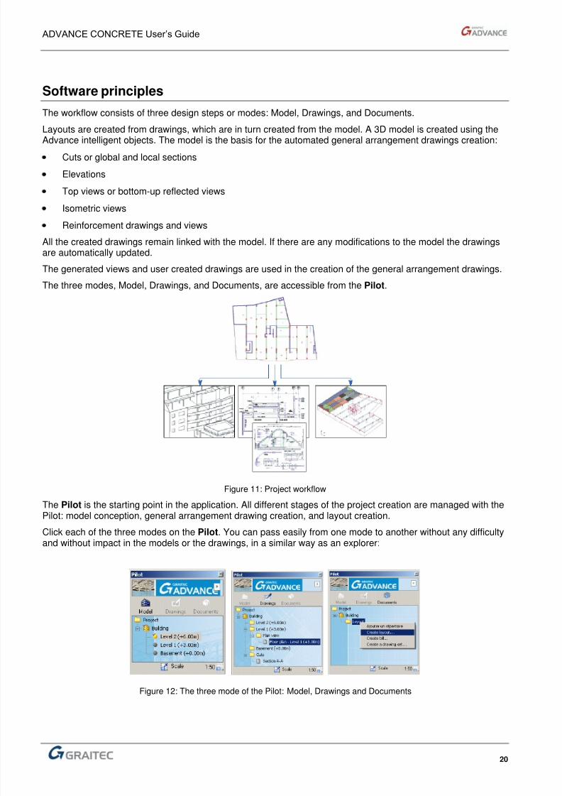
The workflow consists of three design steps or modes: Model, Drawings, and Documents.
Layouts are created from drawings, which are in turn created from the model. A 3D model is created using the
Advance intelligent objects. The model is the basis for the automated general arrangement drawings creation:
Cuts or global and local sections
Elevations
Top views or bottom-up reflected views
Isometric views
Reinforcement drawings and views
All the created drawings remain linked with the model. If there are any modifications to the model the drawingsare automatically updated.
The generated views and user created drawings are used in the creation of the general arrangement drawings.
The three modes, Model, Drawings, and Documents, are accessible from the Pilot.
Figure 11: Project workflow
The Pilot is the starting point in the application. All different stages of the project creation are managed with thePilot: model conception, general arrangement drawing creation, and layout creation.
Click each of the three modes on the Pilot. You can pass easily from one mode to another without any difficultyand without impact in the models or the drawings, in a similar way as an explorer:
Figure 12: The three mode of the Pilot: Model, Drawings and Documents
8/3/2019 AC UserGuide 2011 en Metric
http://slidepdf.com/reader/full/ac-userguide-2011-en-metric 21/114
ADVANCE CONCRETE User’s Guide
21
Model mode
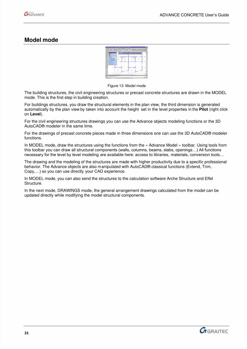
Figure 13: Model mode
The building structures, the civil engineering structures or precast concrete structures are drawn in the MODELmode. This is the first step in building creation.
For buildings structures, you draw the structural elements in the plan view, the third dimension is generatedautomatically by the plan view by taken into account the height set in the level properties in the Pilot (right clickon Level).
For the civil engineering structures drawings you can use the Advance objects modeling functions or the 3DAutoCAD® modeler in the same time.
For the drawings of precast concrete pieces made in three dimensions one can use the 3D AutoCAD® modelerfunctions.
In MODEL mode, draw the structures using the functions from the « Advance Model » toolbar. Using tools fromthis toolbar you can draw all structural components (walls, columns, beams, slabs, openings…) All functionsnecessary for the level by level modeling are available here: access to libraries, materials, conversion tools…
The drawing and the modeling of the structures are made with higher productivity due to a specific professionalbehavior. The Advance objects are also manipulated with AutoCAD® classical functions (Extend, Trim,Copy,…) so you can use directly your CAD experience.
In MODEL mode, you can also send the structures to the calculation software Arche Structure and Effel
Structure.
In the next mode, DRAWINGS mode, the general arrangement drawings calculated from the model can beupdated directly while modifying the model structural components.
8/3/2019 AC UserGuide 2011 en Metric
http://slidepdf.com/reader/full/ac-userguide-2011-en-metric 22/114
ADVANCE CONCRETE User’s Guide
22
Drawings mode
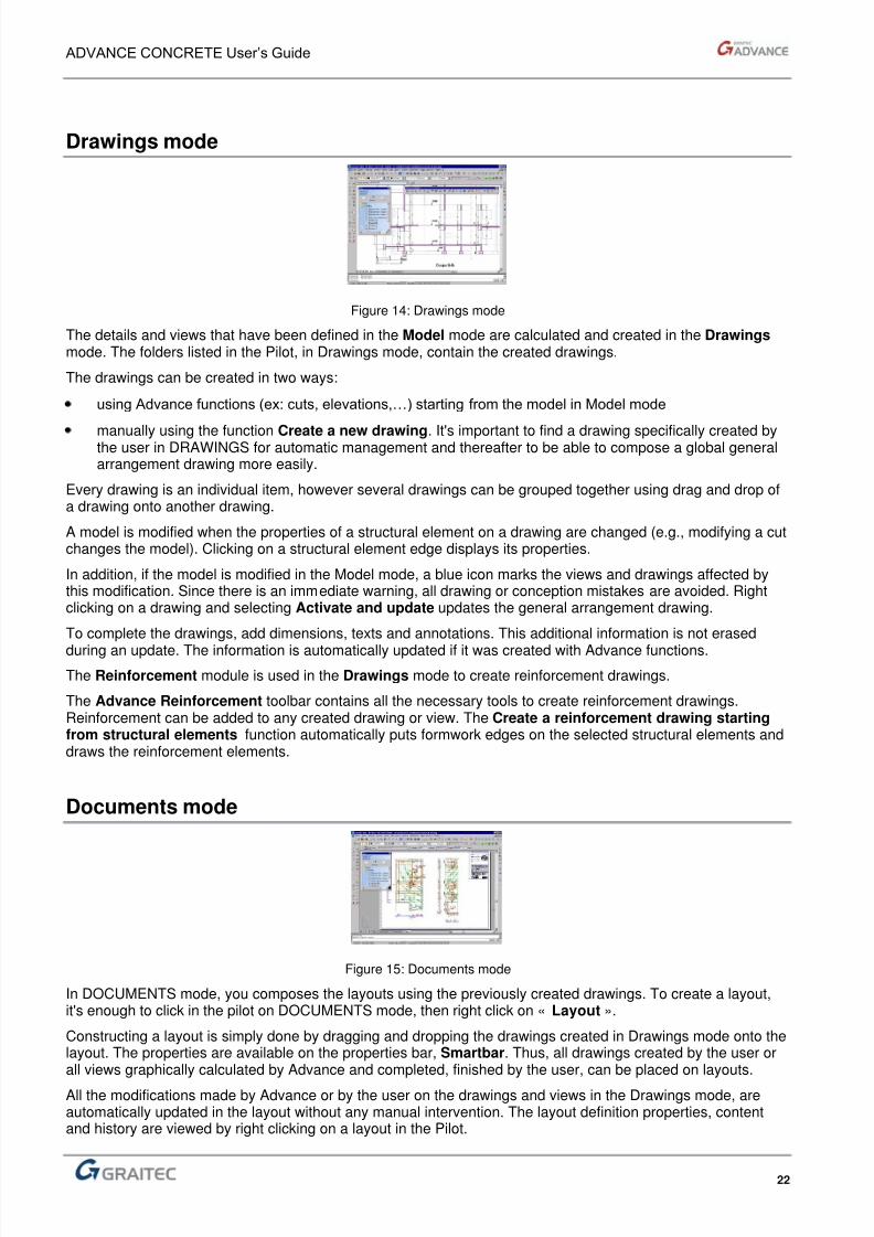
Figure 14: Drawings mode
The details and views that have been defined in the Model mode are calculated and created in the Drawings mode. The folders listed in the Pilot, in Drawings mode, contain the created drawings.
The drawings can be created in two ways:
using Advance functions (ex: cuts, elevations,…) starting from the model in Model mode
manually using the function Create a new drawing. It's important to find a drawing specifically created bythe user in DRAWINGS for automatic management and thereafter to be able to compose a global generalarrangement drawing more easily.
Every drawing is an individual item, however several drawings can be grouped together using drag and drop ofa drawing onto another drawing.
A model is modified when the properties of a structural element on a drawing are changed (e.g., modifying a cutchanges the model). Clicking on a structural element edge displays its properties.
In addition, if the model is modified in the Model mode, a blue icon marks the views and drawings affected bythis modification. Since there is an immediate warning, all drawing or conception mistakes are avoided. Rightclicking on a drawing and selecting Activate and update updates the general arrangement drawing.
To complete the drawings, add dimensions, texts and annotations. This additional information is not erased
during an update. The information is automatically updated if it was created with Advance functions.
The Reinforcement module is used in the Drawings mode to create reinforcement drawings.
The Advance Reinforcement toolbar contains all the necessary tools to create reinforcement drawings.Reinforcement can be added to any created drawing or view. The Create a reinforcement drawing startingfrom structural elements function automatically puts formwork edges on the selected structural elements anddraws the reinforcement elements.
Documents mode
Figure 15: Documents mode
In DOCUMENTS mode, you composes the layouts using the previously created drawings. To create a layout,it's enough to click in the pilot on DOCUMENTS mode, then right click on « Layout ».
Constructing a layout is simply done by dragging and dropping the drawings created in Drawings mode onto thelayout. The properties are available on the properties bar, Smartbar. Thus, all drawings created by the user orall views graphically calculated by Advance and completed, finished by the user, can be placed on layouts.
All the modifications made by Advance or by the user on the drawings and views in the Drawings mode, areautomatically updated in the layout without any manual intervention. The layout definition properties, contentand history are viewed by right clicking on a layout in the Pilot.

8/3/2019 AC UserGuide 2011 en Metric
http://slidepdf.com/reader/full/ac-userguide-2011-en-metric 23/114
ADVANCE CONCRETE User’s Guide
23
Architect – design department – construction companies interface
From the architect...
With the AutoCAD® entity conversion tool, architect drawings are converted to Advance models. Theconversion of basic 2D entities into structural elements accelerates the modeling step.
This functionality is accessed by clicking Convert an AutoCAD® entity on the Model toolbar.
Advance can easily convert elements from an architectural model into structural elements using the AutodeskArchitectural Desktop® platform. The architectural drawings are used to get the construction drawings and the3D model.
...To the construction company
Exporting a standard 2D DWG file from a general arrangement drawing or an Advance layout provides acontractor with a general arrangement drawing in a digital format.
To export a DWG file, right click a drawing or layout and select Export to DWG.
In DOCUMENTS mode, proceed in the same way to export a complete paper plan.
The DWG files created by this method only contain AutoCAD® classic entities without any Advance information.
Find more about Archi-BE interface…
Advance offers you the possibility to start from an architectural drawing file in order to draw the structure quickly.
It is possible to recover the information in two different ways, depending on the type of the architectural drawing.
Figure 16: Requalification of 2D entities in structural objects
8/3/2019 AC UserGuide 2011 en Metric
http://slidepdf.com/reader/full/ac-userguide-2011-en-metric 24/114
ADVANCE CONCRETE User’s Guide
24
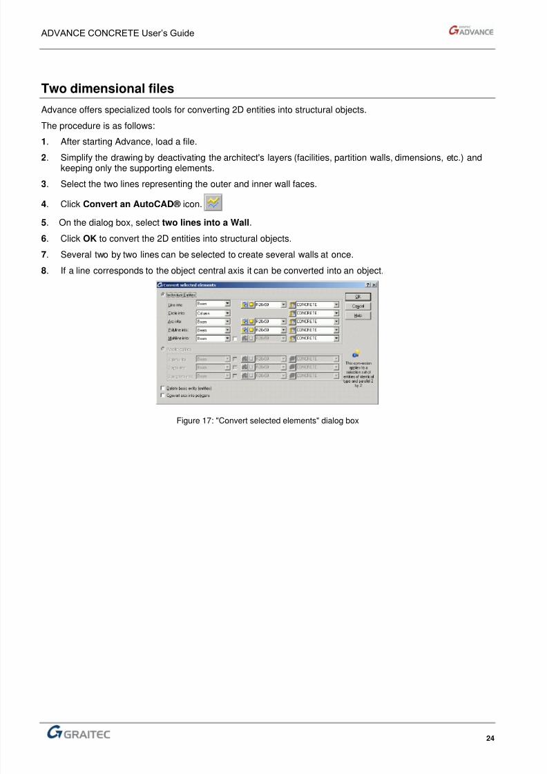
Two dimensional files
Advance offers specialized tools for converting 2D entities into structural objects.
The procedure is as follows:
1. After starting Advance, load a file.
2. Simplify the drawing by deactivating the architect's layers (facilities, partition walls, dimensions, etc.) andkeeping only the supporting elements.
3. Select the two lines representing the outer and inner wall faces.
4. Click Convert an AutoCAD® icon.
5. On the dialog box, select two lines into a Wall.
6. Click OK to convert the 2D entities into structural objects.
7. Several two by two lines can be selected to create several walls at once.
8. If a line corresponds to the object central axis it can be converted into an object.
Figure 17: "Convert selected elements" dialog box

8/3/2019 AC UserGuide 2011 en Metric
http://slidepdf.com/reader/full/ac-userguide-2011-en-metric 25/114
ADVANCE CONCRETE User’s Guide
25
The drawing software – calculation software interface
The same structural model must be able to be used for several applications: the structure created in Advance inMODEL mode is used to create all the execution drawings and it's exploited also to get the engineer's
calculations using the suitable calculation programs.Activate the toolbar « Advance Analyse » by right clicking on a Advance functionalities toolbar.
Figure 18: Analysis and Design toolbar
Export the Model to Arche Building structure
Draw your project in Advance, then click Export to Arche Building Structure. Coupled with Arche, yourstructure is exported directly in the Structure software. Arche Structure gets the calculations of load distribution
according to the traditional method.
Export the Model to Effel Structure
In the same idea, for the more deeper calculations (seismic calculation, wind bracing,…), click on the icon Export to Effel Structure to study the structure using the finite elements calculation method.
Export the Model to Effel Structure
Advance models can be also exported in the Effel Advanced, Graitec new analysis software.
Advance – Arche Structure models synchronization
You can entirely synchronize Arche and Advance models using the synchronization and real time informationtool. This tool allows reinforcing the collaboration between the engineer and the designer. For example, if theengineer changes the position or the dimension of a structural element, the designer is warned and he canaccept or reject this modification. A specific detailed interface allows viewing and sorting the changes appearedin the structure.
Figure 19: “Synchronization” dialog box
Export the Advance structural elements to Arche Reinforcement Modules
With Arche Reinforcement Modules, you can query an individual structural element. Select an Advanceelement and export it directly to the reinforcement module in order to get preliminary dimensioning of theconcrete element and also the reinforcement.

8/3/2019 AC UserGuide 2011 en Metric
http://slidepdf.com/reader/full/ac-userguide-2011-en-metric 26/114
ADVANCE CONCRETE User’s Guide
26
The automatic and assisted reinforcement
Due to Advance's reinforcement module, directly connected to Arche modules, you can create reinforcementdrawings for each structural element (walls, columns,…) with a single click !
Select an element, right-click and select « Create a reinforcement plan ». The reinforcement drawing of thiselement is instantly displayed. This reinforcement plan is created using the calculation facility of Arche. It's nowpossible to modify or to adapt the result by importing again the reinforcement plan in Advance and addingreinforcements, reference marks, dimensions or other types of notations. Then a reinforcement list can begenerated to take in account the modifications.
User interface
AutoCAD® environment
A familiar environment is maintained since Advance is fully integrated into AutoCAD®. Customizable Advance
Concrete toolbars are added to the list of available AutoCAD® toolbars.
The Advance main menu provides quick access to all program functions.
Figure 20: Advance - User Interface
1: Advance pilot
2: Fast access menu
3: Smartbar
4: Advance main menu
5: Advance toolbars
6: Command line

8/3/2019 AC UserGuide 2011 en Metric
http://slidepdf.com/reader/full/ac-userguide-2011-en-metric 27/114
ADVANCE CONCRETE User’s Guide
27
Smartbar
Each object (model elements, dimensions, symbols...) has a properties bar, called Smartbar, for modifying theobject's essential attributes.
Figure 21: Smartbar for slab elements
The smartbar is automatically activated in two instances:
When an object creation command starts, the smartbar of that object appears. During thecreation process, one or several object attributes can be modified.
When one or several objects of the same type are selected, one or several attributes can bemodified. The modifications are confirmed by pressing Enter.
Click to access the element’s detailed properties.

8/3/2019 AC UserGuide 2011 en Metric
http://slidepdf.com/reader/full/ac-userguide-2011-en-metric 28/114
ADVANCE CONCRETE User’s Guide
28
Toolbars
Project Settings toolbar
The Project Settings toolbar contains all the commands to access the libraries.
This… Function
Units
Access the Layer name Manager
Define the Preferences
Access the Material library
Access the Geometry library
Access the Door and Window library
Access the Piles library
Access the Representation style library
Access the Bars library
Access the lap table
Access the hook table
Access rebar rounding rules
Access to the shape library
Default values for steel grade and concrete covers
Access the Mesh library
Access to the bar supports library
Bar supports design rules
Weight review
Load a project
Save the project
8/3/2019 AC UserGuide 2011 en Metric
http://slidepdf.com/reader/full/ac-userguide-2011-en-metric 29/114
ADVANCE CONCRETE User’s Guide
29
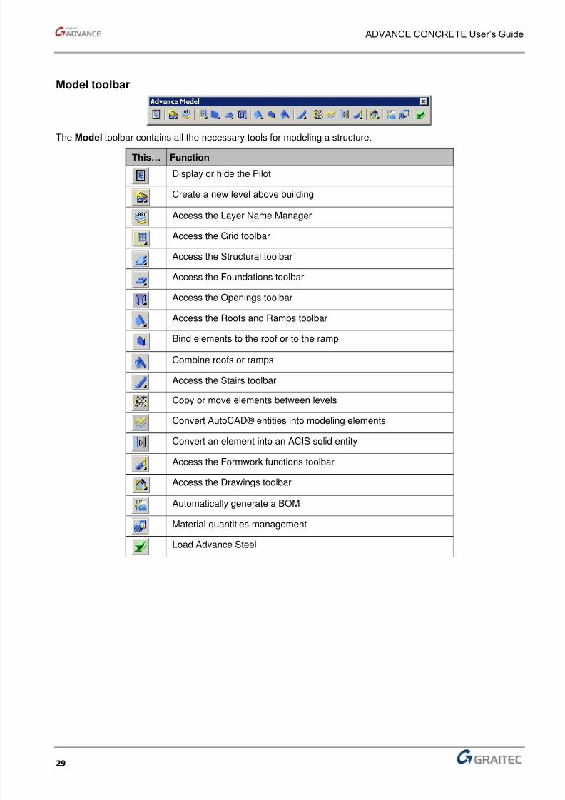
Model toolbar
The Model toolbar contains all the necessary tools for modeling a structure.
This… Function
Display or hide the Pilot
Create a new level above building
Access the Layer Name Manager
Access the Grid toolbar
Access the Structural toolbar
Access the Foundations toolbar
Access the Openings toolbar
Access the Roofs and Ramps toolbar
Bind elements to the roof or to the ramp
Combine roofs or ramps
Access the Stairs toolbar
Copy or move elements between levels
Convert AutoCAD® entities into modeling elements
Convert an element into an ACIS solid entity
Access the Formwork functions toolbar
Access the Drawings toolbar
Automatically generate a BOM
Material quantities management
Load Advance Steel

8/3/2019 AC UserGuide 2011 en Metric
http://slidepdf.com/reader/full/ac-userguide-2011-en-metric 30/114
8/3/2019 AC UserGuide 2011 en Metric
http://slidepdf.com/reader/full/ac-userguide-2011-en-metric 31/114
ADVANCE CONCRETE User’s Guide
31
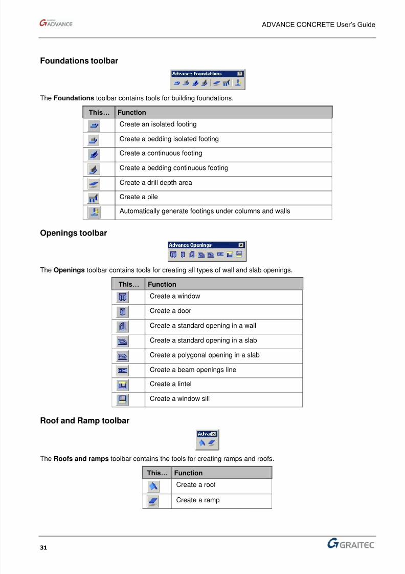
Foundations toolbar
The Foundations toolbar contains tools for building foundations.
This… Function
Create an isolated footing
Create a bedding isolated footing
Create a continuous footing
Create a bedding continuous footing
Create a drill depth area
Create a pile
Automatically generate footings under columns and walls
Openings toolbar
The Openings toolbar contains tools for creating all types of wall and slab openings.
This… Function
Create a window
Create a door
Create a standard opening in a wall
Create a standard opening in a slab
Create a polygonal opening in a slab
Create a beam openings line
Create a lintel
Create a window sill
Roof and Ramp toolbar
The Roofs and ramps toolbar contains the tools for creating ramps and roofs.
This… Function
Create a roof
Create a ramp
8/3/2019 AC UserGuide 2011 en Metric
http://slidepdf.com/reader/full/ac-userguide-2011-en-metric 32/114
ADVANCE CONCRETE User’s Guide
32
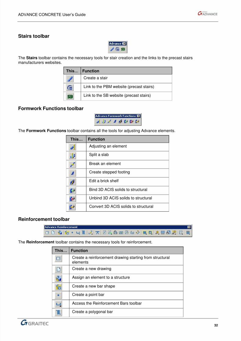
Stairs toolbar
The Stairs toolbar contains the necessary tools for stair creation and the links to the precast stairsmanufacturers websites.
This… Function
Create a stair
Link to the PBM website (precast stairs)
Link to the SB website (precast stairs)
Formwork Functions toolbar
The Formwork Functions toolbar contains all the tools for adjusting Advance elements.
This… Function
Adjusting an element
Split a slab
Break an element
Create stepped footing
Edit a brick shelf
Bind 3D ACIS solids to structural
Unbind 3D ACIS solids to structural
Convert 3D ACIS solids to structural
Reinforcement toolbar
The Reinforcement toolbar contains the necessary tools for reinforcement.
This… Function
Create a reinforcement drawing starting from structuralelements
Create a new drawing
Assign an element to a structure
Create a new bar shape
Create a point bar
Access the Reinforcement Bars toolbar
Create a polygonal bar

8/3/2019 AC UserGuide 2011 en Metric
http://slidepdf.com/reader/full/ac-userguide-2011-en-metric 33/114
ADVANCE CONCRETE User’s Guide
33
This… Function
Break a bar
Create a separator
Create a simple mesh
Access the Meshes Scraps toolbar
Create a simple mesh outline
Create a mesh row
Trim one or several meshes
Create a bent mesh
Create a mesh cut
Access the Distribution toolbar
Access to the Edit distribution toolbar
Access the Reinforcement symbols toolbar
Create a distribution dimension
Create a bar or mesh bending detail
Access the Automatic drafting toolbar
View the bar library
View the mesh library
Access the Reinforcement renumbering toolbar
Access the Lists toolbar
Meshes Scraps toolbar
The Meshes Scraps toolbar contains tools for creating new meshes starting from scraps.
This… Function
Create a mesh starting from scraps
Automatically optimize mesh rests
8/3/2019 AC UserGuide 2011 en Metric
http://slidepdf.com/reader/full/ac-userguide-2011-en-metric 34/114

8/3/2019 AC UserGuide 2011 en Metric
http://slidepdf.com/reader/full/ac-userguide-2011-en-metric 35/114
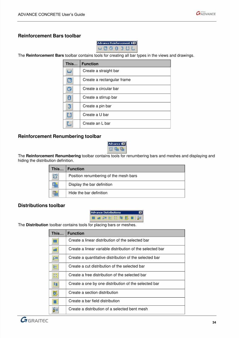
ADVANCE CONCRETE User’s Guide
35
Distribution Editor toolbar
The Distribution Editor contains the tools for editing the distributions.
This… Function
Trim the distribution bars
Edit a distribution
Apply a multiplication factor to the distribution
Display the hidden element (definition or distribution bar)
Reinforcement 3D Viewer toolbar
The Reinforcement 3D Viewer toolbar contains all tools for viewing the 3D reinforcement cages.
This… Function
Create a reinforcement view
Create a new reinforcement elevation
Create a new reinforcement cut
Delete a reinforcement view
Select and define the view
Start the 3D viewer
Clash check
Sketch Designer toolbar
The Sketch Designer toolbar contains all the necessary tools for creating a dynamic reinforcement solution.
This… Function
Create a sketch point by translation
Create a sketch point at the edge intersection
Create a sketch point at the edge-planeintersection
Create a sketch point on a line
Define an angle
Define a distanceDefine a factor
Define a vector
8/3/2019 AC UserGuide 2011 en Metric
http://slidepdf.com/reader/full/ac-userguide-2011-en-metric 36/114
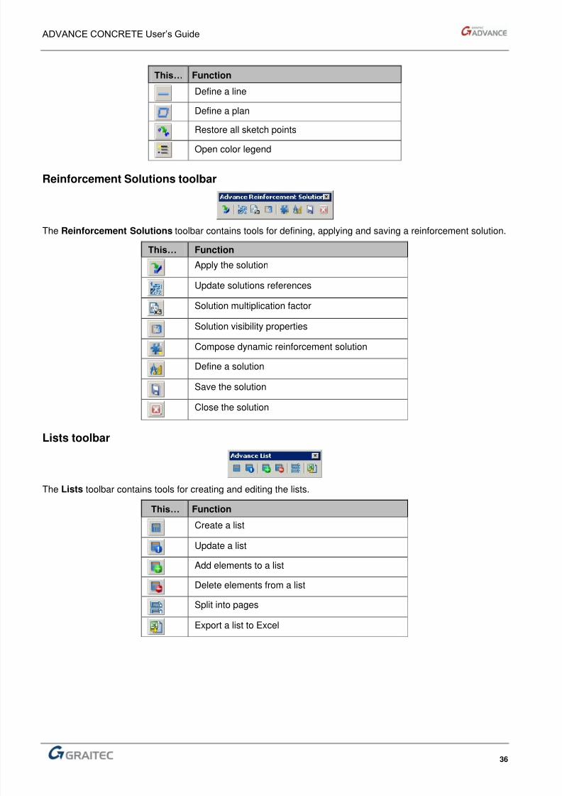
ADVANCE CONCRETE User’s Guide
36
This… Function
Define a line
Define a plan Restore all sketch points
Open color legend
Reinforcement Solutions toolbar
The Reinforcement Solutions toolbar contains tools for defining, applying and saving a reinforcement solution.
This… Function
Apply the solution Update solutions references Solution multiplication factor Solution visibility properties Compose dynamic reinforcement solution
Define a solution
Save the solution
Close the solution
Lists toolbar
The Lists toolbar contains tools for creating and editing the lists.
This… Function
Create a list
Update a list
Add elements to a list
Delete elements from a list
Split into pages
Export a list to Excel
8/3/2019 AC UserGuide 2011 en Metric
http://slidepdf.com/reader/full/ac-userguide-2011-en-metric 37/114
ADVANCE CONCRETE User’s Guide
37
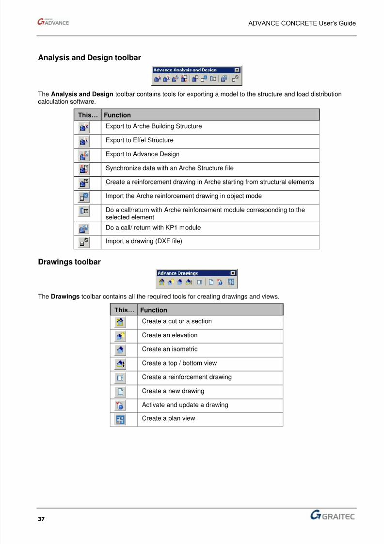
Analysis and Design toolbar
The Analysis and Design toolbar contains tools for exporting a model to the structure and load distributioncalculation software.
This… Function
Export to Arche Building Structure
Export to Effel Structure
Export to Advance Design
Synchronize data with an Arche Structure file
Create a reinforcement drawing in Arche starting from structural elements
Import the Arche reinforcement drawing in object mode
Do a call/return with Arche reinforcement module corresponding to theselected element
Do a call/ return with KP1 module
Import a drawing (DXF file)
Drawings toolbar
The Drawings toolbar contains all the required tools for creating drawings and views.
This… Function
Create a cut or a section
Create an elevation
Create an isometric
Create a top / bottom view
Create a reinforcement drawing
Create a new drawing
Activate and update a drawing
Create a plan view
8/3/2019 AC UserGuide 2011 en Metric
http://slidepdf.com/reader/full/ac-userguide-2011-en-metric 38/114
ADVANCE CONCRETE User’s Guide
38
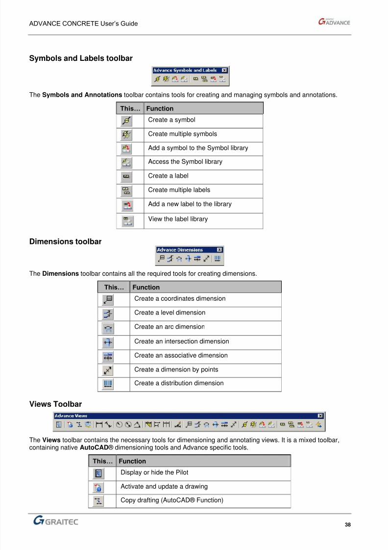
Symbols and Labels toolbar
The Symbols and Annotations toolbar contains tools for creating and managing symbols and annotations.
This… Function
Create a symbol
Create multiple symbols
Add a symbol to the Symbol library
Access the Symbol library
Create a label
Create multiple labels
Add a new label to the library
View the label library
Dimensions toolbar
The Dimensions toolbar contains all the required tools for creating dimensions.
This… FunctionCreate a coordinates dimension
Create a level dimension
Create an arc dimension
Create an intersection dimension
Create an associative dimension
Create a dimension by points
Create a distribution dimension
Views Toolbar
The Views toolbar contains the necessary tools for dimensioning and annotating views. It is a mixed toolbar,containing native AutoCAD ® dimensioning tools and Advance specific tools.
This… Function
Display or hide the Pilot
Activate and update a drawing
Copy drafting (AutoCAD® Function)
8/3/2019 AC UserGuide 2011 en Metric
http://slidepdf.com/reader/full/ac-userguide-2011-en-metric 39/114
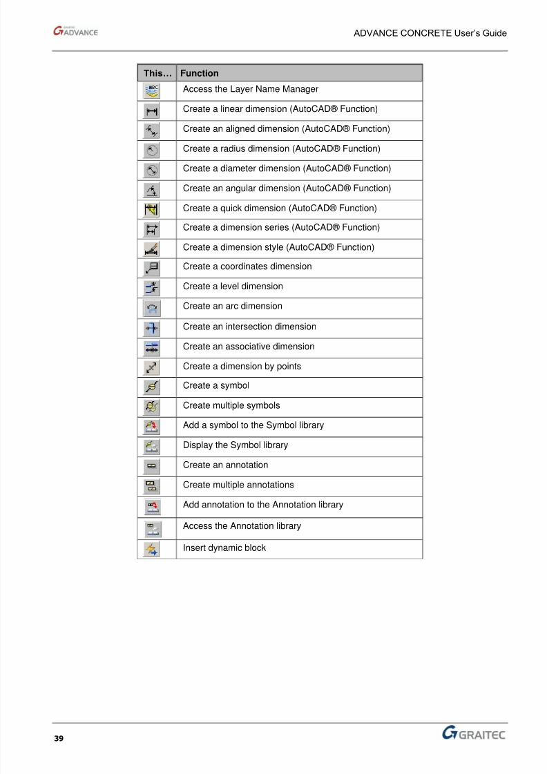
ADVANCE CONCRETE User’s Guide
39
This… Function
Access the Layer Name Manager
Create a linear dimension (AutoCAD® Function)
Create an aligned dimension (AutoCAD® Function)
Create a radius dimension (AutoCAD® Function)
Create a diameter dimension (AutoCAD® Function)
Create an angular dimension (AutoCAD® Function)
Create a quick dimension (AutoCAD® Function)
Create a dimension series (AutoCAD® Function)
Create a dimension style (AutoCAD® Function)
Create a coordinates dimension
Create a level dimension
Create an arc dimension
Create an intersection dimension
Create an associative dimension
Create a dimension by points
Create a symbol
Create multiple symbols
Add a symbol to the Symbol library
Display the Symbol library
Create an annotation
Create multiple annotations
Add annotation to the Annotation library
Access the Annotation library
Insert dynamic block
8/3/2019 AC UserGuide 2011 en Metric
http://slidepdf.com/reader/full/ac-userguide-2011-en-metric 40/114
ADVANCE CONCRETE User’s Guide
40
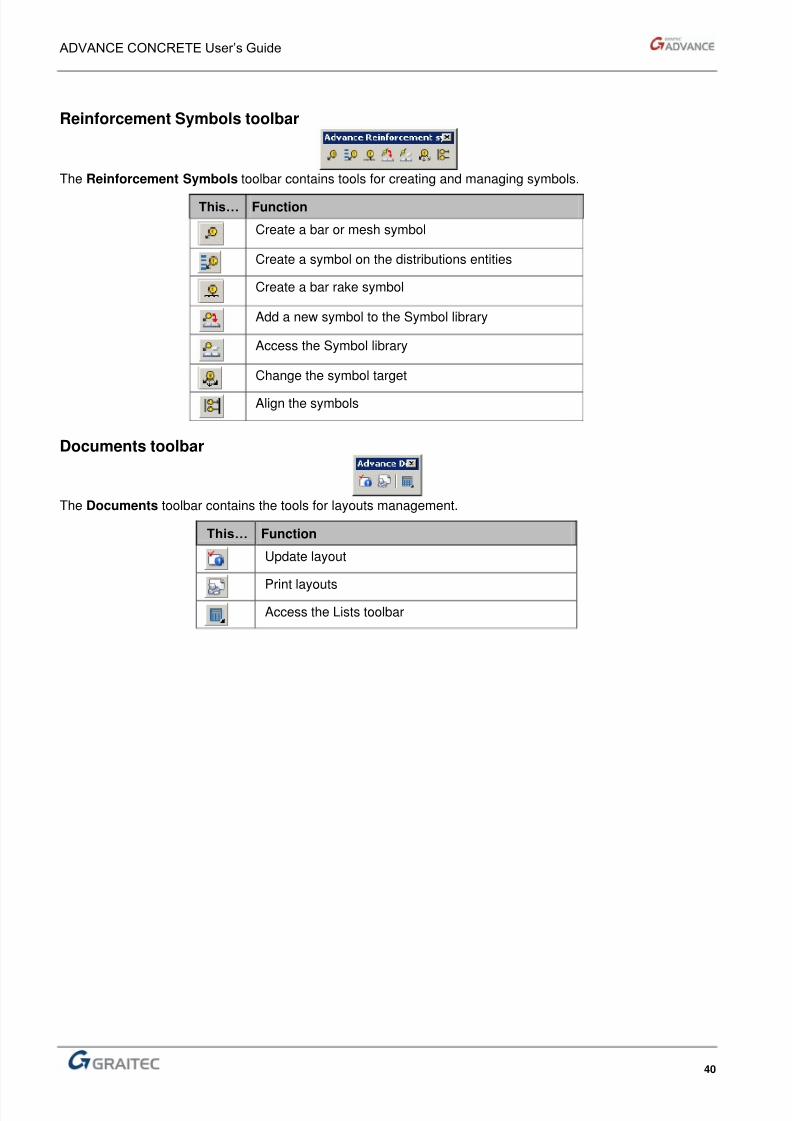
Reinforcement Symbols toolbar
The Reinforcement Symbols toolbar contains tools for creating and managing symbols.
This… Function
Create a bar or mesh symbol
Create a symbol on the distributions entities
Create a bar rake symbol
Add a new symbol to the Symbol library
Access the Symbol library
Change the symbol target
Align the symbols
Documents toolbar
The Documents toolbar contains the tools for layouts management.
This… Function
Update layout
Print layouts
Access the Lists toolbar

8/3/2019 AC UserGuide 2011 en Metric
http://slidepdf.com/reader/full/ac-userguide-2011-en-metric 41/114
ADVANCE CONCRETE User’s Guide
41
Tools toolbar
The Tools toolbar contains the necessary tools for selecting and displaying elements.
This… Function
Activate the AutoUCS tool
Isolate the selected elements
Hide the selected elements
Display elements by type
Select elements using multiple criteria
Select elements by type
Re-label elements
Launch the Simple Identification tool
Launch the Multiple Identification tool
Insert dynamic block
Bar Editor toolbar
The Bar Editor toolbar contains the necessary tools for breaking and editing bars.
This… Function
Break a bar
Edit a bar
Automatic Drafting toolbar
The Automatic Drafting toolbars contains tools for creating automatically symbols, dimensions and bendingdetails on the desired element.
This… Function
Automatic drafting – Symbols and dimensions
Automatic drafting – Bending details

8/3/2019 AC UserGuide 2011 en Metric
http://slidepdf.com/reader/full/ac-userguide-2011-en-metric 42/114

8/3/2019 AC UserGuide 2011 en Metric
http://slidepdf.com/reader/full/ac-userguide-2011-en-metric 43/114
ADVANCE CONCRETE User’s Guide
43
Advance menus
Main menu
All the commands and dialog boxes are accessed using the Advance Concrete drop-down menu.
Using the Advance menu
After having selected the drop-down menu, select a command by clicking on its name. For example:
Figure 22: Advance Main menu
An arrow following a command name indicates thata submenu is available.
A command followed by (...) indicates that a dialogbox is displayed with additional options.
The different submenus of the main menu
Button Function
Pilot Display or hide the Pilot
Project Access project management commands
Model Access structure object creation commands
Reinforcement Access reinforcement drawings creation commands
Drawings Access drawings and views creation commands
Visual elements Access visual elements creation commands
Documents Access document creation commandsTools Access Advance utilities
Help Access online help and other documentation sources
Note:
You can access the menus and commands by pressing <ALT> key and the menu shortcut key. For example, toopen Advance menu, press <ALT + A>.
When the mouse cursor hovers over an icon or a menu item, the status bar displays a short description.
8/3/2019 AC UserGuide 2011 en Metric
http://slidepdf.com/reader/full/ac-userguide-2011-en-metric 44/114
ADVANCE CONCRETE User’s Guide
44
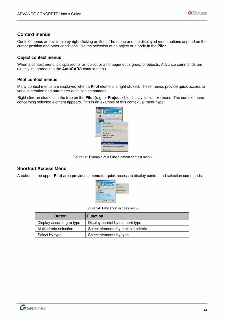
Context menus
Context menus are available by right clicking an item. The menu and the displayed menu options depend on thecursor position and other conditions, like the selection of an object or a node in the Pilot.
Object context menus
When a context menu is displayed for an object or a homogeneous group of objects, Advance commands aredirectly integrated into the AutoCAD ® context menu.
Pilot context menus
Many context menus are displayed when a Pilot element is right clicked. These menus provide quick access tovarious creation and parameter definition commands.
Right click an element in the tree on the Pilot (e.g., « Project ») to display its context menu. The context menuconcerning selected element appears. This is an example of this contextual menu type:
Figure 23: Example of a Pilot element context menu
Shortcut Access MenuA button in the upper Pilot area provides a menu for quick access to display control and selection commands.
Figure 24: Pilot short access menu
Button Function
Display according to type Display control by element type
Multicriteria selection Select elements by multiple criteria
Select by type Select elements by type
8/3/2019 AC UserGuide 2011 en Metric
http://slidepdf.com/reader/full/ac-userguide-2011-en-metric 45/114
ADVANCE CONCRETE User’s Guide
45
Utilities
There are key tools that are vital for the proper use of Advance modules. The online help is a good source forinformation on activating and using these tools.
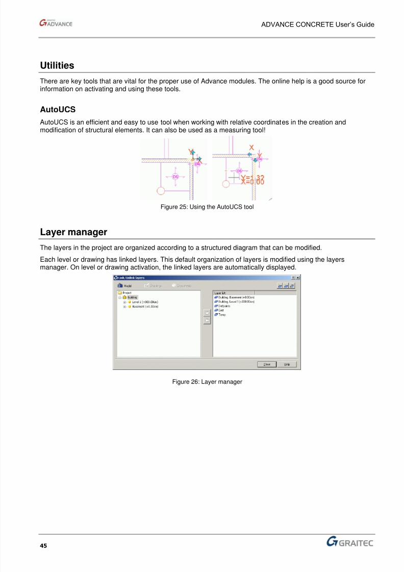
AutoUCS
AutoUCS is an efficient and easy to use tool when working with relative coordinates in the creation andmodification of structural elements. It can also be used as a measuring tool!
Figure 25: Using the AutoUCS tool
Layer manager
The layers in the project are organized according to a structured diagram that can be modified.
Each level or drawing has linked layers. This default organization of layers is modified using the layersmanager. On level or drawing activation, the linked layers are automatically displayed.
Figure 26: Layer manager
8/3/2019 AC UserGuide 2011 en Metric
http://slidepdf.com/reader/full/ac-userguide-2011-en-metric 46/114
ADVANCE CONCRETE User’s Guide
46
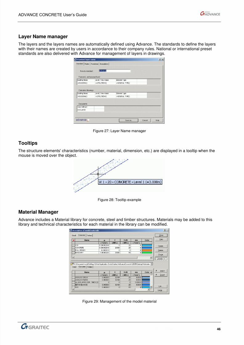
Layer Name manager
The layers and the layers names are automatically defined using Advance. The standards to define the layerswith their names are created by users in accordance to their company rules. National or international presetstandards are also delivered with Advance for management of layers in drawings.
Figure 27: Layer Name manager
Tooltips
The structure elements' characteristics (number, material, dimension, etc.) are displayed in a tooltip when themouse is moved over the object.
Figure 28: Tooltip example
Material Manager
Advance includes a Material library for concrete, steel and timber structures. Materials may be added to thislibrary and technical characteristics for each material in the library can be modified.
Figure 29: Management of the model material

8/3/2019 AC UserGuide 2011 en Metric
http://slidepdf.com/reader/full/ac-userguide-2011-en-metric 47/114
ADVANCE CONCRETE User’s Guide
47
Object Geometry Manager
All types of geometries can be drawn in Advance.
Each Advance project includes the following categories:
Volumes (applicable for isolated footings, defined by an attach point, an angle and a volume)
Sections (applicable for beams, columns and continuous footings, obtained by extruding thesection along the element's main axis)
Thicknesses (applicable for walls and slabs, obtained by extrusion of their contour depending onthe thickness).
Different objects can share these stored geometries.
For example, all beams with 20x50 rectangular sections, in a project reference a single section. Thismechanism considerably reduces the amount of memory space used by Advance.
Figure 30: Object Geometry Manager
Representation Styles ManagerIn Advance, every object type can have a representation style. A representation style is a set of parametersthat define the representation for objects of the same type. Object appearance (hatching, line thickness, etc.) iseasily controlled using the representation styles.
Representation styles are stored in a manager. For example, the columns lines' color is changed by modifyingthe representation style. There is no need to select all columns as they are automatically updated.
Figure 31: Representation styles manager
8/3/2019 AC UserGuide 2011 en Metric
http://slidepdf.com/reader/full/ac-userguide-2011-en-metric 48/114
ADVANCE CONCRETE User’s Guide
48
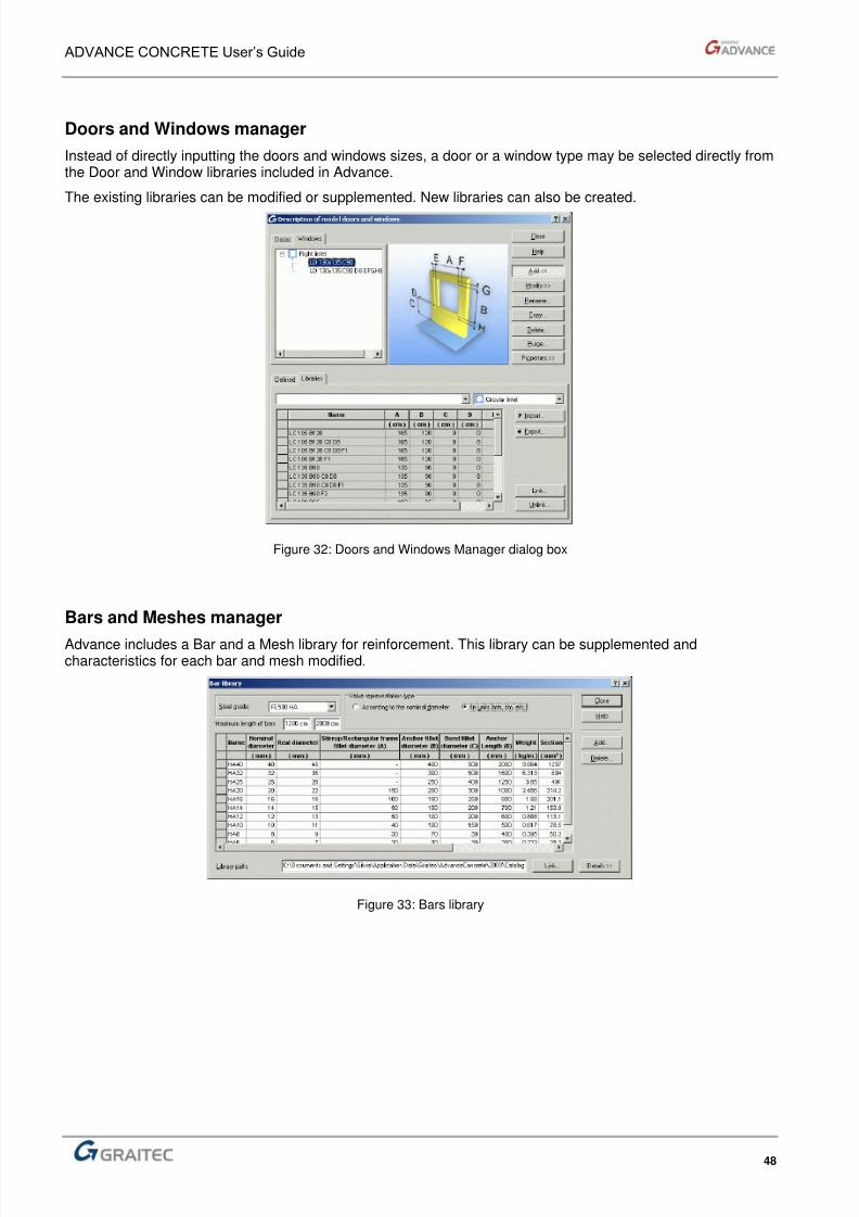
Doors and Windows manager
Instead of directly inputting the doors and windows sizes, a door or a window type may be selected directly fromthe Door and Window libraries included in Advance.
The existing libraries can be modified or supplemented. New libraries can also be created.
Figure 32: Doors and Windows Manager dialog box
Bars and Meshes manager
Advance includes a Bar and a Mesh library for reinforcement. This library can be supplemented andcharacteristics for each bar and mesh modified.
Figure 33: Bars library

8/3/2019 AC UserGuide 2011 en Metric
http://slidepdf.com/reader/full/ac-userguide-2011-en-metric 49/114
ADVANCE CONCRETE User’s Guide
49
Multicriteria object selection
This is a powerful tool for sorting and selecting structural elements that enables the user to select the exactobjects to modify.
Example: Beams number 101 to 107, having a 20x30 section and made by C25 from level 1 are selected.
Figure 34: “Multicriteria selection” dialog box
Displaying objects by type
Only objects of a specified type (column, wall, etc.) in the structure are displayed.
Figure 35: Displaying objects by type
Automatic Reinforcement Objects
For certain structural objects a reinforcement type is automatically assigned during object creation. Thesereinforcement styles are entirely customizable.
Figure 36: Automatic Reinforcement Wizards

8/3/2019 AC UserGuide 2011 en Metric
http://slidepdf.com/reader/full/ac-userguide-2011-en-metric 50/114
ADVANCE CONCRETE User’s Guide
50
Viewer 3D
In Advance, although all reinforcement element are drawn in 2D, they can be materialized in 3D with the 3Dviewer.
Using the information from the 2D drawings in the views, the viewer easily recreates the reinforcement cages. It
works on bars, meshes and bent meshes. The 3D reinforcement cage can be stored as a drawing and printed.
Figure 37: 3D Viewer
8/3/2019 AC UserGuide 2011 en Metric
http://slidepdf.com/reader/full/ac-userguide-2011-en-metric 51/114
Chapter 3Using Advance
In this Chapter
■ Basic settings
■ Construct a model
■ Create drawings
■ Create a layout
■ Export the model for calculations
■ Create reinforcement drawings
8/3/2019 AC UserGuide 2011 en Metric
http://slidepdf.com/reader/full/ac-userguide-2011-en-metric 52/114
ADVANCE CONCRETE User’s Guide
52
Advance by examples
Formwork and Implementation
This example illustrates how to:
Quickly draw a simple building with foundation and two levels
Automatically create a section
Place an associative dimension
Create an A4 layout.
This example has 16 steps and takes about 30 minutes.
Reinforcement
In this exercise, the building model will be used to create a wall reinforcement drawing.
This example has 8 steps.
8/3/2019 AC UserGuide 2011 en Metric
http://slidepdf.com/reader/full/ac-userguide-2011-en-metric 53/114
ADVANCE CONCRETE User’s Guide
53
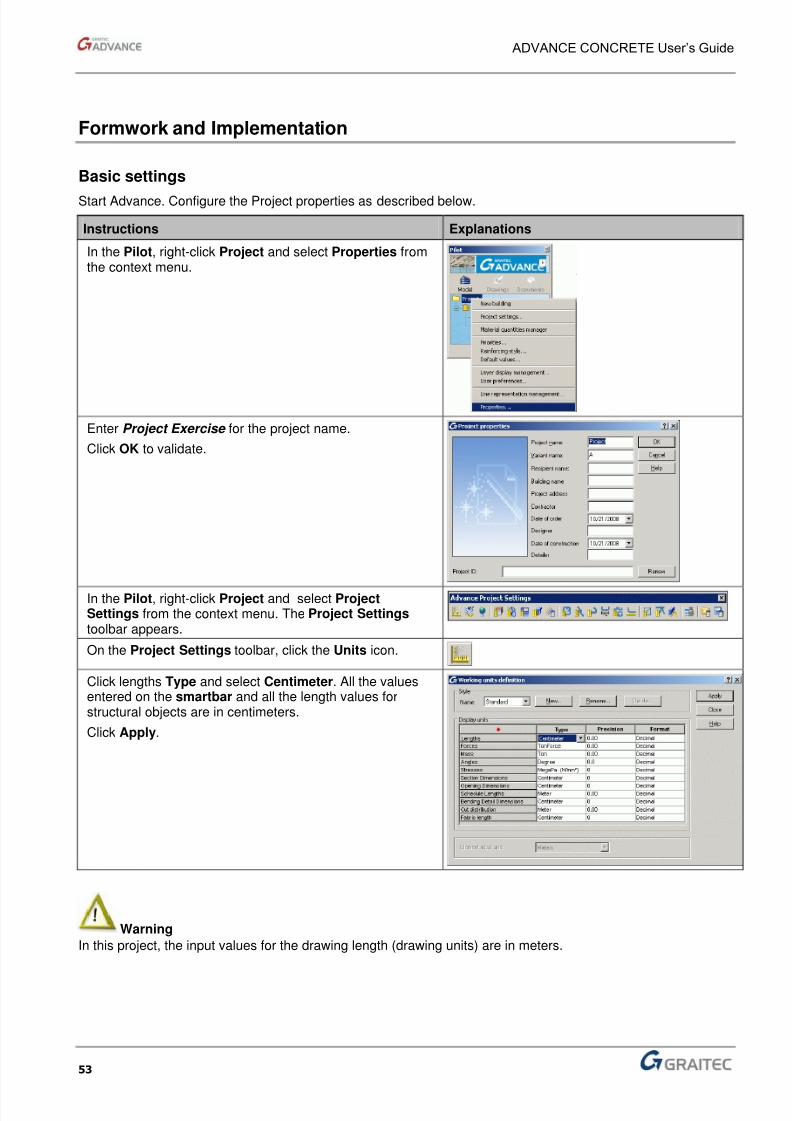
Formwork and Implementation
Basic settings
Start Advance. Configure the Project properties as described below.
Instructions Explanations
In the Pilot, right-click Project and select Properties fromthe context menu.
Enter Project Exercise for the project name.
Click OK to validate.
In the Pilot, right-click Project and select ProjectSettings from the context menu. The Project Settings toolbar appears.
On the Project Settings toolbar, click the Units icon.
Click lengths Type and select Centimeter. All the valuesentered on the smartbar and all the length values forstructural objects are in centimeters.
Click Apply.
Warning
In this project, the input values for the drawing length (drawing units) are in meters.

8/3/2019 AC UserGuide 2011 en Metric
http://slidepdf.com/reader/full/ac-userguide-2011-en-metric 54/114
ADVANCE CONCRETE User’s Guide
54
Construct a model
Step 1: Create continuous walls
The first step consists of drawing foundation walls.
Instructions Explanations
On the Model toolbar, Structural flyout, clickCreate a wall in the current level.
Activate Ortho mode by pressing F8. Press F8.
Click on the graphic area to define a starting
point and input these values:
Move the mouse cursor in the X direction, enter 2 on the
command line and press Enter. Move the mouse cursor in the Y direction, enter 2 andpress Enter
Place the mouse cursor in X direction and input 5 andpress Enter
Move the mouse cursor in the Y direction, enter 3 andpress Enter
Move the mouse cursor in the -X direction and enter 7 and press Enter
Move the mouse cursor in the -Y direction, enter 5 andpress Enter
Press Esc to end.
8/3/2019 AC UserGuide 2011 en Metric
http://slidepdf.com/reader/full/ac-userguide-2011-en-metric 55/114
ADVANCE CONCRETE User’s Guide
55
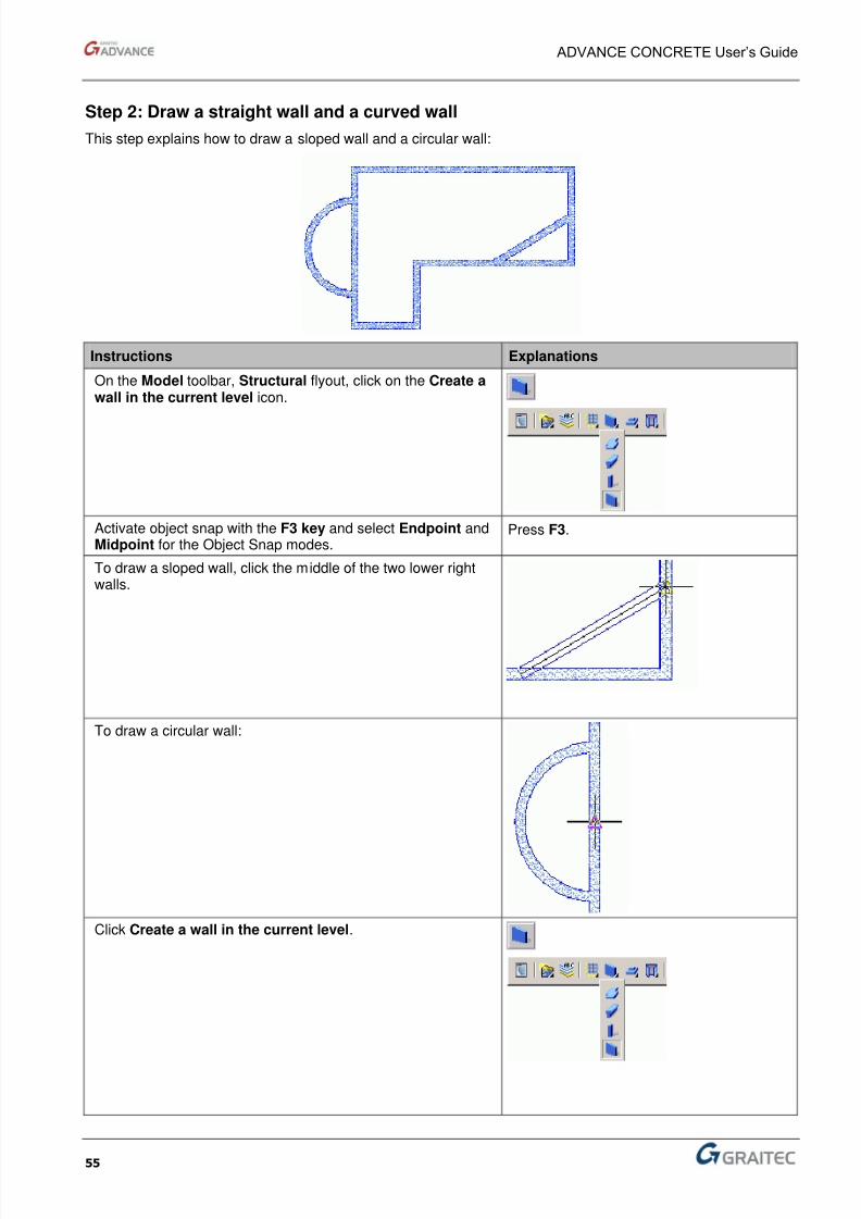
Step 2: Draw a straight wall and a curved wall
This step explains how to draw a sloped wall and a circular wall:
Instructions Explanations
On the Model toolbar, Structural flyout, click on the Create awall in the current level icon.
Activate object snap with the F3 key and select Endpoint andMidpoint for the Object Snap modes.
Press F3.
To draw a sloped wall, click the middle of the two lower rightwalls.
To draw a circular wall:
Click Create a wall in the current level.

8/3/2019 AC UserGuide 2011 en Metric
http://slidepdf.com/reader/full/ac-userguide-2011-en-metric 56/114
ADVANCE CONCRETE User’s Guide
56
Instructions Explanations
On the Tools toolbar, click Activate AutoUCS.
Click the upper corner of the wall to place AutoUCS origin.
On the command line, enter the values: 1,0 .
Press Enter.
>>Target point or X, Y coordinates: 1,0
On the command line type CE (Center) and press Enter.
Click the middle of the left vertical wall.
Click the vertical wall to end the circular wall as shown in thefigure.
The drawing should look similar to the upper drawing.
Step 3: Adjust the walls
This step illustrates how to trim the walls.
Instructions Explanations
On the AutoCAD® Modify toolbar, select the Trim command.
Click on the 3 parts of the wall to be removed.
Note: The AutoCAD® Chamfer command works onAdvance entities and could have been used instead of theTrim command. You could have used it here.
The drawing should look similar to the upper drawing.
1
2
3
8/3/2019 AC UserGuide 2011 en Metric
http://slidepdf.com/reader/full/ac-userguide-2011-en-metric 57/114
ADVANCE CONCRETE User’s Guide
57
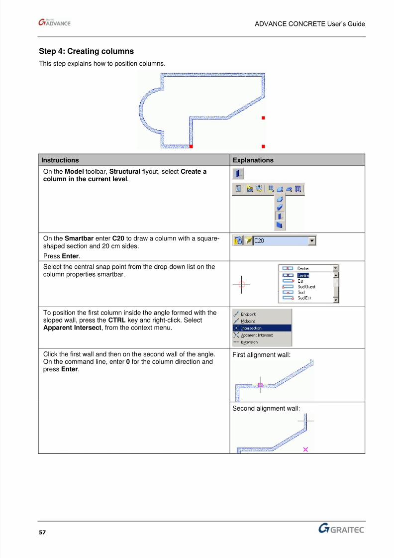
Step 4: Creating columns
This step explains how to position columns.
Instructions Explanations
On the Model toolbar, Structural flyout, select Create acolumn in the current level.
On the Smartbar enter C20 to draw a column with a square-shaped section and 20 cm sides.
Press Enter.
Select the central snap point from the drop-down list on thecolumn properties smartbar.
To position the first column inside the angle formed with thesloped wall, press the CTRL key and right-click. SelectApparent Intersect, from the context menu.
Click the first wall and then on the second wall of the angle.On the command line, enter 0 for the column direction andpress Enter.
First alignment wall:
Second alignment wall:

8/3/2019 AC UserGuide 2011 en Metric
http://slidepdf.com/reader/full/ac-userguide-2011-en-metric 58/114
ADVANCE CONCRETE User’s Guide
58
Instructions Explanations
The first column is now positioned. To create a copy 2 m in the –Y axis direction, use the AutoCAD® standard copy function.
For this, use AutoCAD® standard copy function.
Click Copy.
Select the column and press Enter. Select the column againas the base point.
Enter @0,-2 on the command line to copy the column 2 maway.
Using the same process, copy the second column 5 m in the –X direction.
The drawing should look similar to the upper drawing.
Step 5: Create the beams and slabs
This step demonstrates how to draw beams and position slabs.
Instructions Description
On the Model toolbar, Structural flyout, select the Create abeam in the current level icon.

8/3/2019 AC UserGuide 2011 en Metric
http://slidepdf.com/reader/full/ac-userguide-2011-en-metric 59/114
ADVANCE CONCRETE User’s Guide
59
Instructions Description
Draw the three beams by connecting the wall reference axesand the center of the columns as shown in the figure.
On the Model toolbar, Structural flyout, select Create aslab in the current level.
Enter D (Detection) on the command line and press Enter. D then press Enter
Click on the three areas (as shown in the figure) to create theslabs. The slabs are automatically created by boundarydetection.
Press Esc to finish.
1
2
3
8/3/2019 AC UserGuide 2011 en Metric
http://slidepdf.com/reader/full/ac-userguide-2011-en-metric 60/114
ADVANCE CONCRETE User’s Guide
60
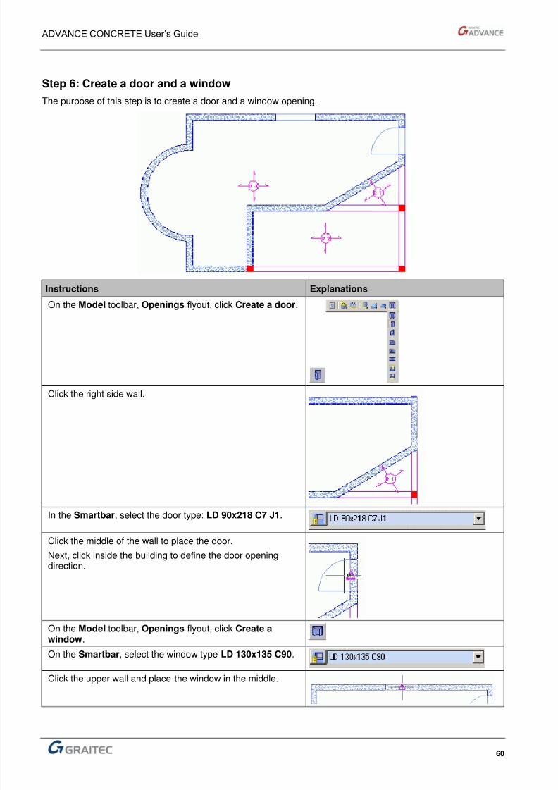
Step 6: Create a door and a window
The purpose of this step is to create a door and a window opening.
Instructions Explanations
On the Model toolbar, Openings flyout, click Create a door.
Click the right side wall.
In the Smartbar, select the door type: LD 90x218 C7 J1.
Click the middle of the wall to place the door.
Next, click inside the building to define the door openingdirection.
On the Model toolbar, Openings flyout, click Create awindow.
On the Smartbar, select the window type LD 130x135 C90.
Click the upper wall and place the window in the middle.

8/3/2019 AC UserGuide 2011 en Metric
http://slidepdf.com/reader/full/ac-userguide-2011-en-metric 61/114
ADVANCE CONCRETE User’s Guide
61
Step 7: Use the AutoUCS tool to position a slab hole
The purpose of this step is to create an opening in a slab.
Instructions Explanations
On the Model toolbar, Openings flyout select Create aslab opening.
Click the biggest slab. The opening symbol appears.
On the Tools toolbar, click Activate AutoUCS.
Click the upper left corner of the slab to place the AutoUCSorigin.
On the command line, enter: 1,1.
Press Enter to validate.
>>Target point or X, Y coordinates: 1, 1
Enter 0 for the rotation angle and then press Enter.
The drawing should look similar to the upper drawing.

8/3/2019 AC UserGuide 2011 en Metric
http://slidepdf.com/reader/full/ac-userguide-2011-en-metric 62/114
ADVANCE CONCRETE User’s Guide
62
Step 8: Automatically create the second level
Instructions Explanations
On the Level toolbar, click Copy the elements ofthe current level to the superior level.
Press Enter to validate. N Double-click Building in the Pilot.
The two levels of the 3D building are displayed.
On the AutoCAD® Visual Styles toolbar, clickRealistic Visual Styles to view the building.
On the AutoCAD® Visual Styles toolbar, click 2DWireframe to return to wireframe mode.

8/3/2019 AC UserGuide 2011 en Metric
http://slidepdf.com/reader/full/ac-userguide-2011-en-metric 63/114
ADVANCE CONCRETE User’s Guide
63
Step 9: Generate foundations
The purpose of this step is to automatically generate the foundation walls and footings for the supportingelements.
Instructions Explanations
On the Model toolbar, Foundation flyout, select Generateautomatic slabs.
Select the Automatic determinations of footings option.Click OK.
The foundations are automatically placed under the firstlevel of the building.
8/3/2019 AC UserGuide 2011 en Metric
http://slidepdf.com/reader/full/ac-userguide-2011-en-metric 64/114
ADVANCE CONCRETE User’s Guide
64
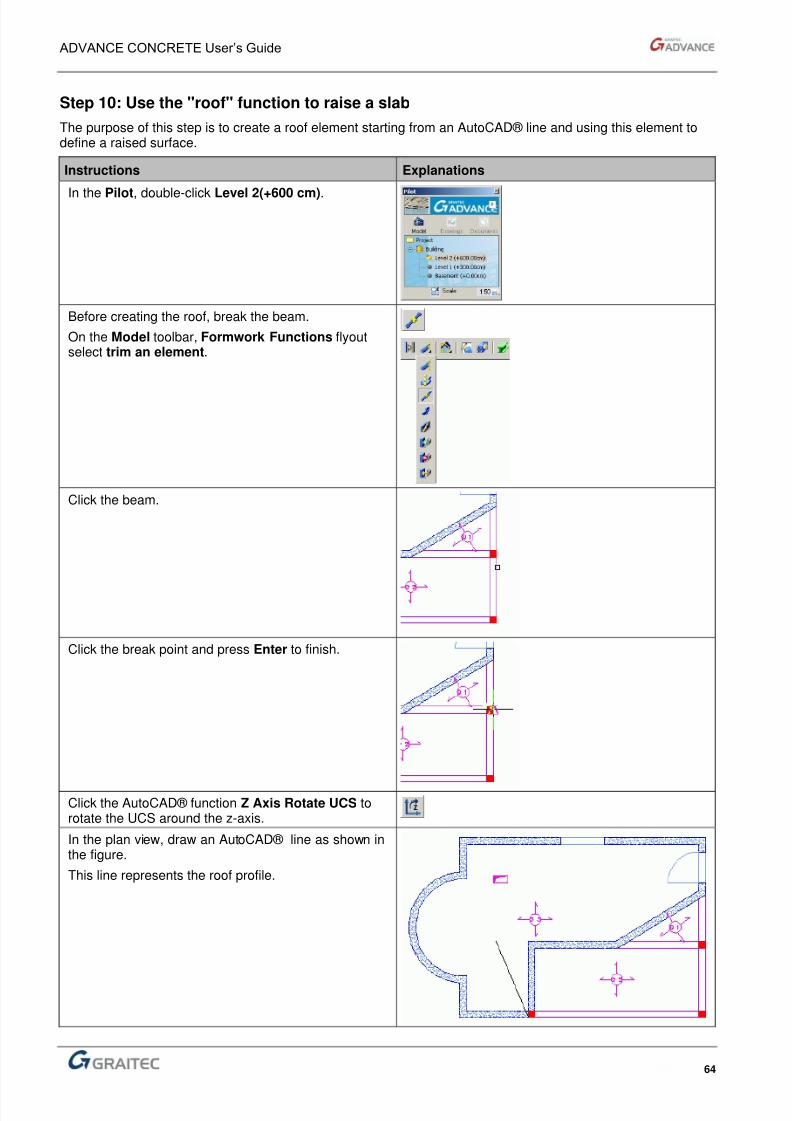
Step 10: Use the "roof" function to raise a slab
The purpose of this step is to create a roof element starting from an AutoCAD® line and using this element todefine a raised surface.
Instructions Explanations
In the Pilot, double-click Level 2(+600 cm).
Before creating the roof, break the beam.
On the Model toolbar, Formwork Functions flyoutselect trim an element.
Click the beam.
Click the break point and press Enter to finish.
Click the AutoCAD® function Z Axis Rotate UCS torotate the UCS around the z-axis.
In the plan view, draw an AutoCAD® line as shown inthe figure.
This line represents the roof profile.
8/3/2019 AC UserGuide 2011 en Metric
http://slidepdf.com/reader/full/ac-userguide-2011-en-metric 65/114
ADVANCE CONCRETE User’s Guide
65
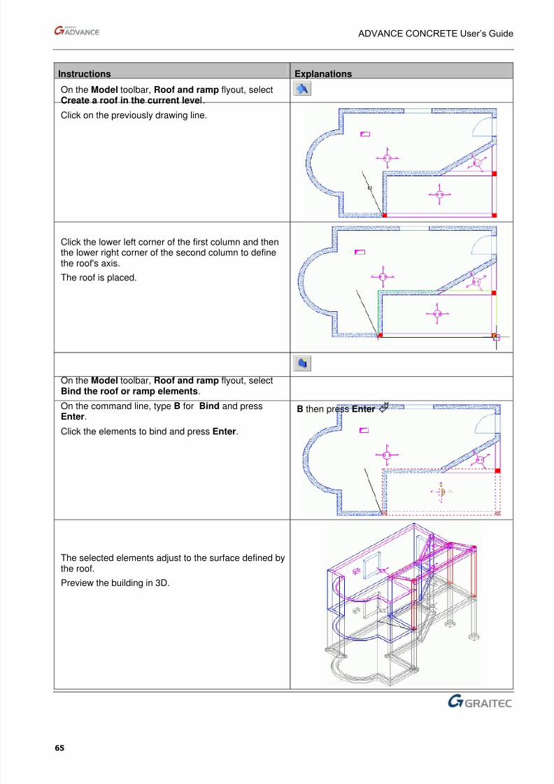
Instructions Explanations
On the Model toolbar, Roof and ramp flyout, selectCreate a roof in the current level.
Click on the previously drawing line.
Click the lower left corner of the first column and thenthe lower right corner of the second column to definethe roof's axis.
The roof is placed.
On the Model toolbar, Roof and ramp flyout, selectBind the roof or ramp elements.
On the command line, type B for Bind and pressEnter. B then press Enter
Click the elements to bind and press Enter.
The selected elements adjust to the surface defined bythe roof.
Preview the building in 3D.
8/3/2019 AC UserGuide 2011 en Metric
http://slidepdf.com/reader/full/ac-userguide-2011-en-metric 66/114
ADVANCE CONCRETE User’s Guide
66
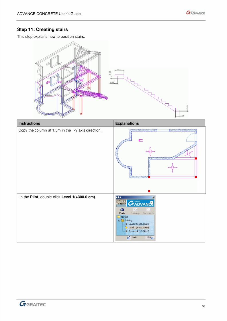
Step 11: Creating stairs
This step explains how to position stairs.
Instructions Explanations
Copy the column at 1.5m in the -y axis direction.
In the Pilot, double-click Level 1(+300.0 cm).

8/3/2019 AC UserGuide 2011 en Metric
http://slidepdf.com/reader/full/ac-userguide-2011-en-metric 67/114
ADVANCE CONCRETE User’s Guide
67
Instructions Explanations
Copy the lower left column 1.5 m in the –Y axisdirection.
On the Model toolbar, Stairs flyout select Create astair.
In the properties dialog box, set the step number to 16.
Add an upper platform width of 72 cm.
Indentation height and width: 20 cm
Set these values on all the properties tabs. Navigatethe tabs using the Previous and Next buttons.
Add a lower platform.
Click the Bottom anchor tab.
Enter the values for the parameters of the bottomanchor:
Height: 12 cm
Width: 28 cm
Tilt width and height: 0 cm
Set these values on all the properties tabs. Navigatethe tabs using the Previous and Next buttons.
Click OK.
8/3/2019 AC UserGuide 2011 en Metric
http://slidepdf.com/reader/full/ac-userguide-2011-en-metric 68/114
ADVANCE CONCRETE User’s Guide
68
Instructions Explanations
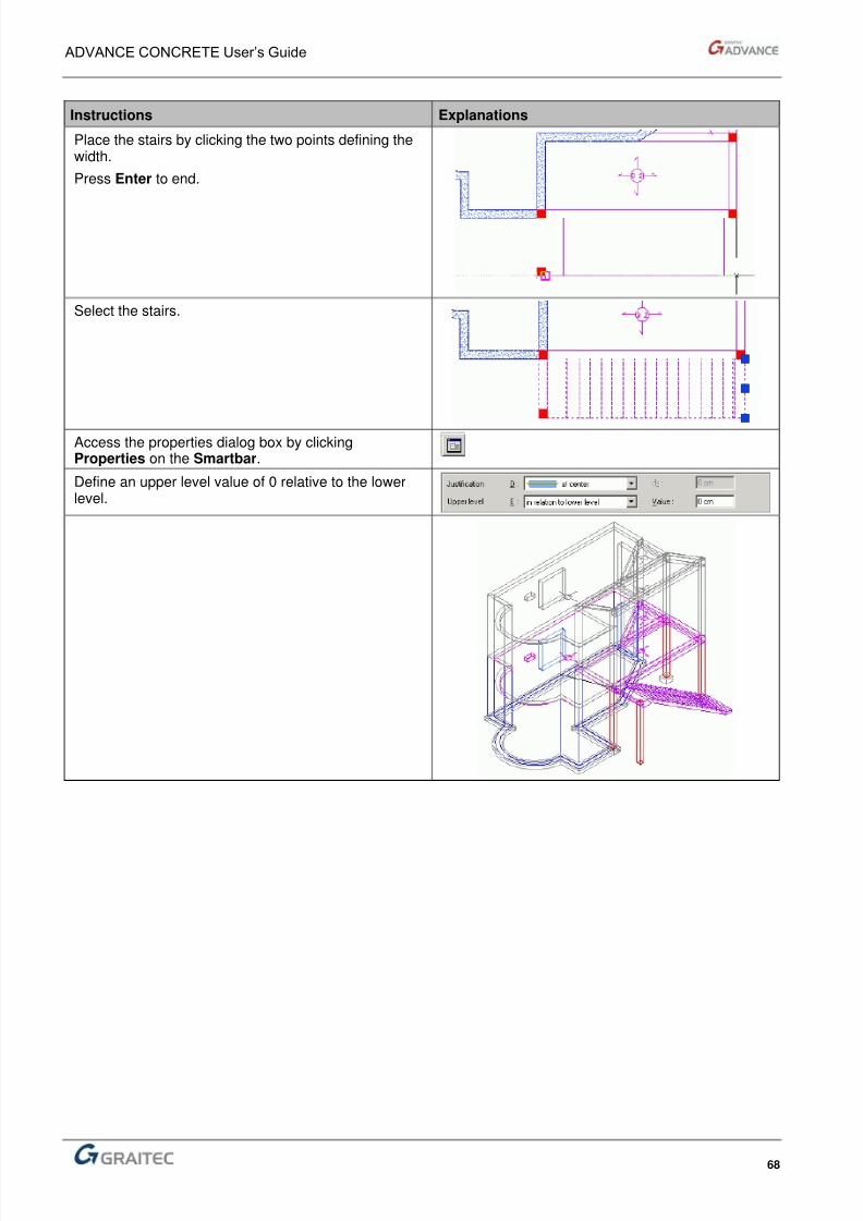
Place the stairs by clicking the two points defining thewidth.
Press Enter to end.
Select the stairs.
Access the properties dialog box by clickingProperties on the Smartbar.
Define an upper level value of 0 relative to the lowerlevel.
8/3/2019 AC UserGuide 2011 en Metric
http://slidepdf.com/reader/full/ac-userguide-2011-en-metric 69/114
ADVANCE CONCRETE User’s Guide
69
Create drawings
The modeling part of the example is completed. The next part consists of the steps to create and fill thedrawings.
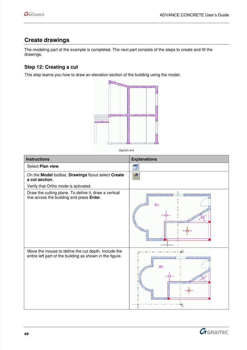
Step 12: Creating a cut
This step learns you how to draw an elevation section of the building using the model.
Instructions Explanations
Select Plan view.
On the Model toolbar, Drawings flyout select Createa cut section.
Verify that Ortho mode is activated.
Draw the cutting plane. To define it, draw a verticalline across the building and press Enter.
Move the mouse to define the cut depth. Include theentire left part of the building as shown in the figure.

8/3/2019 AC UserGuide 2011 en Metric
http://slidepdf.com/reader/full/ac-userguide-2011-en-metric 70/114
8/3/2019 AC UserGuide 2011 en Metric
http://slidepdf.com/reader/full/ac-userguide-2011-en-metric 71/114
8/3/2019 AC UserGuide 2011 en Metric
http://slidepdf.com/reader/full/ac-userguide-2011-en-metric 72/114
8/3/2019 AC UserGuide 2011 en Metric
http://slidepdf.com/reader/full/ac-userguide-2011-en-metric 73/114
ADVANCE CONCRETE User’s Guide
73
Create a layout
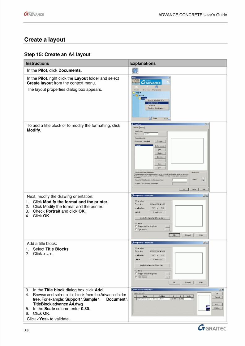
Step 15: Create an A4 layout
Instructions Explanations
In the Pilot, click Documents.
In the Pilot, right click the Layout folder and selectCreate layout from the context menu.
The layout properties dialog box appears.
To add a title block or to modify the formatting, clickModify.
Next, modify the drawing orientation:
1. Click Modify the format and the printer.2. Click Modify the format and the printer.3. Check Portrait and click OK.4. Click OK.
Add a title block:1. Select Title Blocks.2. Click <…>.
3. In the Title block dialog box click Add.4. Browse and select a title block from the Advance folder
tree. For example: Support \ Sample \ Document \
TitleBlock advance A4.dwg 5. In the Scale column enter 0.30.6. Click OK.
Click <Yes> to validate.
8/3/2019 AC UserGuide 2011 en Metric
http://slidepdf.com/reader/full/ac-userguide-2011-en-metric 74/114
ADVANCE CONCRETE User’s Guide
74
Instructions Explanations
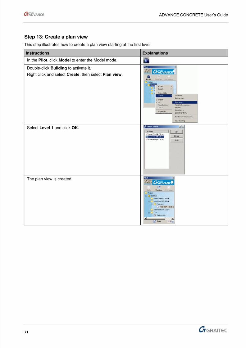
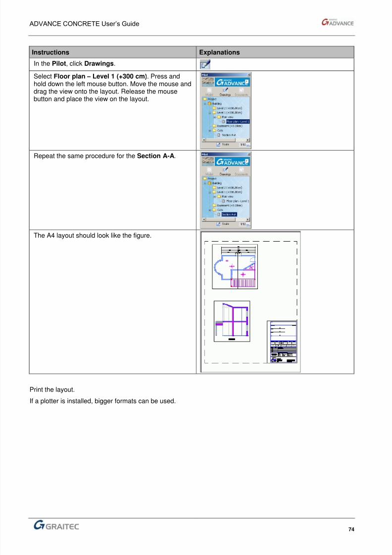
In the Pilot, click Drawings.
Select Floor plan – Level 1 (+300 cm). Press andhold down the left mouse button. Move the mouse anddrag the view onto the layout. Release the mouse
button and place the view on the layout.
Repeat the same procedure for the Section A-A.
The A4 layout should look like the figure.
Print the layout.
If a plotter is installed, bigger formats can be used.
8/3/2019 AC UserGuide 2011 en Metric
http://slidepdf.com/reader/full/ac-userguide-2011-en-metric 75/114
ADVANCE CONCRETE User’s Guide
75
Export the model for calculations
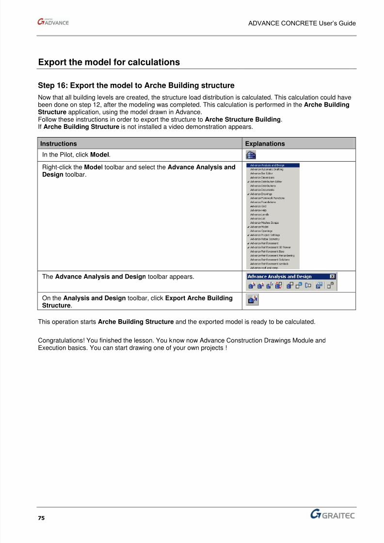
Step 16: Export the model to Arche Building structure
Now that all building levels are created, the structure load distribution is calculated. This calculation could havebeen done on step 12, after the modeling was completed. This calculation is performed in the Arche BuildingStructure application, using the model drawn in Advance.Follow these instructions in order to export the structure to Arche Structure Building.If Arche Building Structure is not installed a video demonstration appears.
Instructions Explanations
In the Pilot, click Model.
Right-click the Model toolbar and select the Advance Analysis andDesign toolbar.
The Advance Analysis and Design toolbar appears.
On the Analysis and Design toolbar, click Export Arche BuildingStructure.
This operation starts Arche Building Structure and the exported model is ready to be calculated.
Congratulations! You finished the lesson. You know now Advance Construction Drawings Module andExecution basics. You can start drawing one of your own projects !

8/3/2019 AC UserGuide 2011 en Metric
http://slidepdf.com/reader/full/ac-userguide-2011-en-metric 76/114

8/3/2019 AC UserGuide 2011 en Metric
http://slidepdf.com/reader/full/ac-userguide-2011-en-metric 77/114
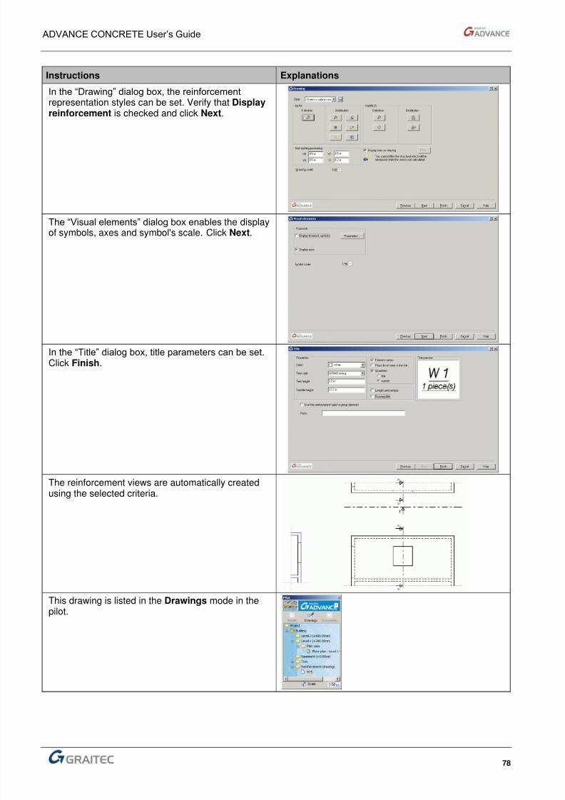
8/3/2019 AC UserGuide 2011 en Metric
http://slidepdf.com/reader/full/ac-userguide-2011-en-metric 78/114
ADVANCE CONCRETE User’s Guide
78
Instructions Explanations
In the “Drawing” dialog box, the reinforcementrepresentation styles can be set. Verify that Displayreinforcement is checked and click Next.
The “Visual elements” dialog box enables the displayof symbols, axes and symbol's scale. Click Next.
In the “Title” dialog box, title parameters can be set.Click Finish.
The reinforcement views are automatically createdusing the selected criteria.
This drawing is listed in the Drawings mode in thepilot.
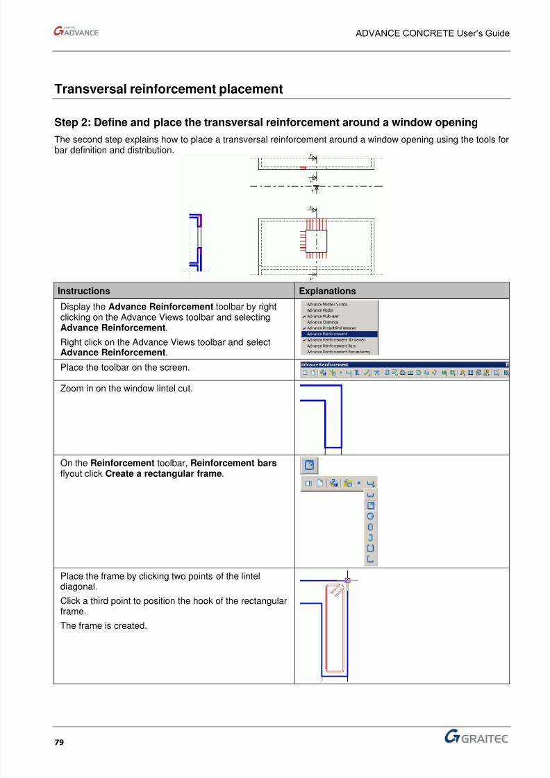
8/3/2019 AC UserGuide 2011 en Metric
http://slidepdf.com/reader/full/ac-userguide-2011-en-metric 79/114
ADVANCE CONCRETE User’s Guide
79
Transversal reinforcement placement
Step 2: Define and place the transversal reinforcement around a window opening
The second step explains how to place a transversal reinforcement around a window opening using the tools forbar definition and distribution.
Instructions Explanations
Display the Advance Reinforcement toolbar by rightclicking on the Advance Views toolbar and selectingAdvance Reinforcement.
Right click on the Advance Views toolbar and selectAdvance Reinforcement.
Place the toolbar on the screen.
Zoom in on the window lintel cut.
On the Reinforcement toolbar, Reinforcement bars flyout click Create a rectangular frame.
Place the frame by clicking two points of the linteldiagonal.
Click a third point to position the hook of the rectangularframe.
The frame is created.
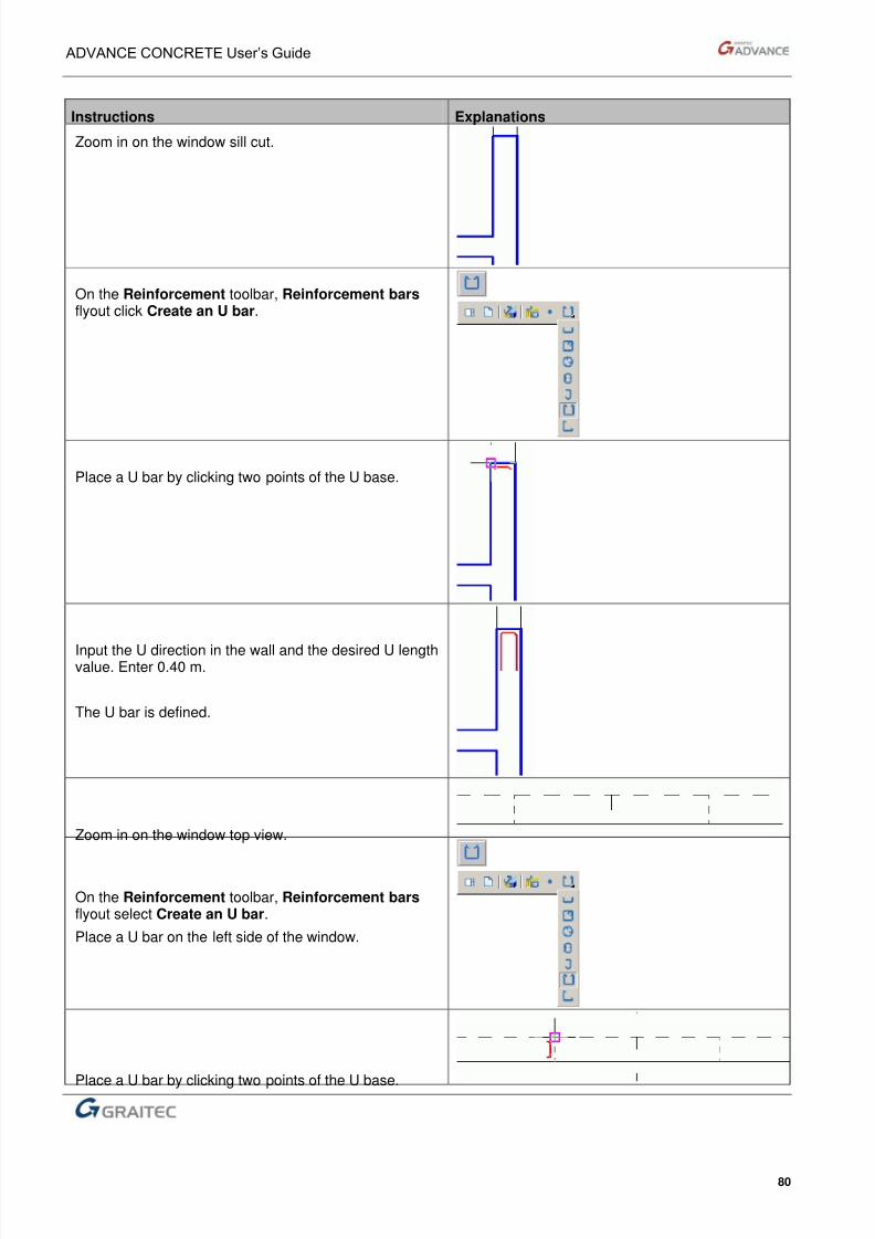
8/3/2019 AC UserGuide 2011 en Metric
http://slidepdf.com/reader/full/ac-userguide-2011-en-metric 80/114
ADVANCE CONCRETE User’s Guide
80
Instructions Explanations
Zoom in on the window sill cut.
On the Reinforcement toolbar, Reinforcement bars flyout click Create an U bar.
Place a U bar by clicking two points of the U base.
Input the U direction in the wall and the desired U lengthvalue. Enter 0.40 m.
The U bar is defined.
Zoom in on the window top view.
On the Reinforcement toolbar, Reinforcement bars flyout select Create an U bar.
Place a U bar on the left side of the window.
Place a U bar by clicking two points of the U base.

8/3/2019 AC UserGuide 2011 en Metric
http://slidepdf.com/reader/full/ac-userguide-2011-en-metric 81/114
ADVANCE CONCRETE User’s Guide
81
Instructions Explanations
Input the U direction in the wall and the desired U lengthvalue. Enter 0.40 m.
The U bar is defined.
Three bars have been defined and must be placed.
Next, you will distribute these bars.
Start by placing the frame.
Zoom in on the frame definition.
On the Reinforcement toolbar, Distributions flyout,select Create a linear distribution.
Click the frame.
The Sideview tool automatically appears as two arrows.This tool sets the distribution bar direction.
Select the horizontal arrow to place this side of therectangular frame on the wall elevation.
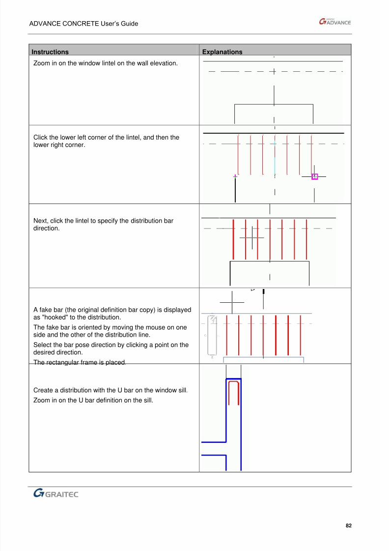
8/3/2019 AC UserGuide 2011 en Metric
http://slidepdf.com/reader/full/ac-userguide-2011-en-metric 82/114
ADVANCE CONCRETE User’s Guide
82
Instructions Explanations
Zoom in on the window lintel on the wall elevation.
Click the lower left corner of the lintel, and then thelower right corner.
Next, click the lintel to specify the distribution bardirection.
A fake bar (the original definition bar copy) is displayedas "hooked" to the distribution.
The fake bar is oriented by moving the mouse on oneside and the other of the distribution line.
Select the bar pose direction by clicking a point on thedesired direction.
The rectangular frame is placed.
Create a distribution with the U bar on the window sill.
Zoom in on the U bar definition on the sill.
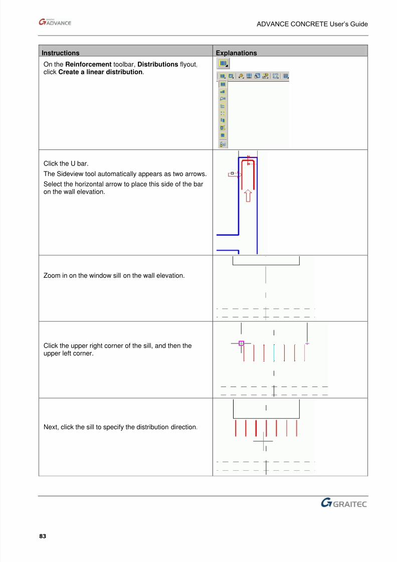
8/3/2019 AC UserGuide 2011 en Metric
http://slidepdf.com/reader/full/ac-userguide-2011-en-metric 83/114
ADVANCE CONCRETE User’s Guide
83
Instructions Explanations
On the Reinforcement toolbar, Distributions flyout,click Create a linear distribution.
Click the U bar.
The Sideview tool automatically appears as two arrows.
Select the horizontal arrow to place this side of the baron the wall elevation.
Zoom in on the window sill on the wall elevation.
Click the upper right corner of the sill, and then theupper left corner.
Next, click the sill to specify the distribution direction.
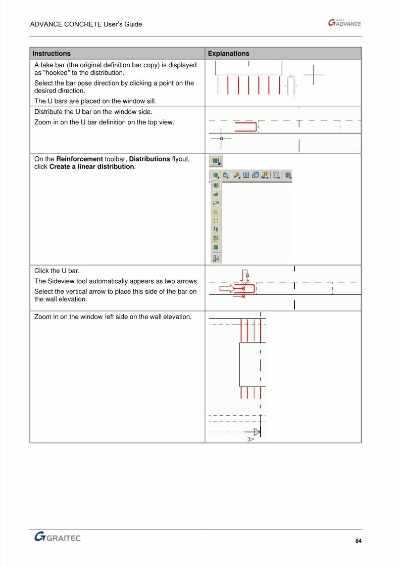
8/3/2019 AC UserGuide 2011 en Metric
http://slidepdf.com/reader/full/ac-userguide-2011-en-metric 84/114
ADVANCE CONCRETE User’s Guide
84
Instructions Explanations
A fake bar (the original definition bar copy) is displayedas "hooked" to the distribution.
Select the bar pose direction by clicking a point on thedesired direction.
The U bars are placed on the window sill.
Distribute the U bar on the window side.
Zoom in on the U bar definition on the top view.
On the Reinforcement toolbar, Distributions flyout,click Create a linear distribution.
Click the U bar.
The Sideview tool automatically appears as two arrows.
Select the vertical arrow to place this side of the bar on
the wall elevation.
Zoom in on the window left side on the wall elevation.

8/3/2019 AC UserGuide 2011 en Metric
http://slidepdf.com/reader/full/ac-userguide-2011-en-metric 85/114
ADVANCE CONCRETE User’s Guide
85
Instructions Explanations
Click the upper left corner of the window, and then thelower right corner.
Next, click the sill to specify the distribution direction.
A fake bar (the original definition bar copy) is displayedas "hooked" to the distribution.
Select the bar pose direction by clicking a point on thedesired direction.
The U bars are placed on the window side.
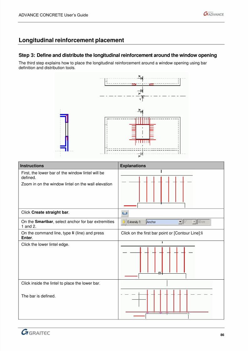
8/3/2019 AC UserGuide 2011 en Metric
http://slidepdf.com/reader/full/ac-userguide-2011-en-metric 86/114
ADVANCE CONCRETE User’s Guide
86
Longitudinal reinforcement placement
Step 3: Define and distribute the longitudinal reinforcement around the window opening
The third step explains how to place the longitudinal reinforcement around a window opening using bardefinition and distribution tools.
Instructions Explanations
First, the lower bar of the window lintel will bedefined.
Zoom in on the window lintel on the wall elevation
Click Create straight bar.
On the Smartbar, select anchor for bar extremities1 and 2.
On the command line, type li (line) and pressEnter.
Click on the first bar point or [Contour Line]:li
Click the lower lintel edge.
Click inside the lintel to place the lower bar.
The bar is defined.
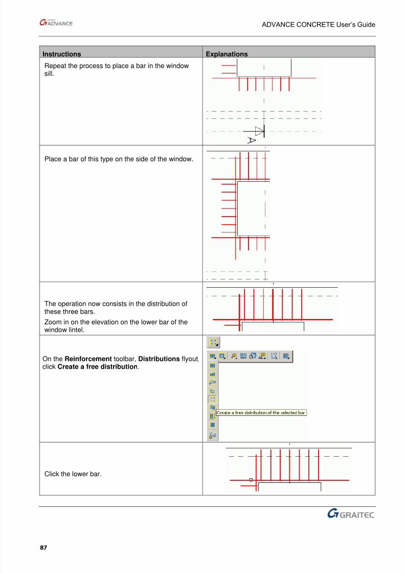
8/3/2019 AC UserGuide 2011 en Metric
http://slidepdf.com/reader/full/ac-userguide-2011-en-metric 87/114
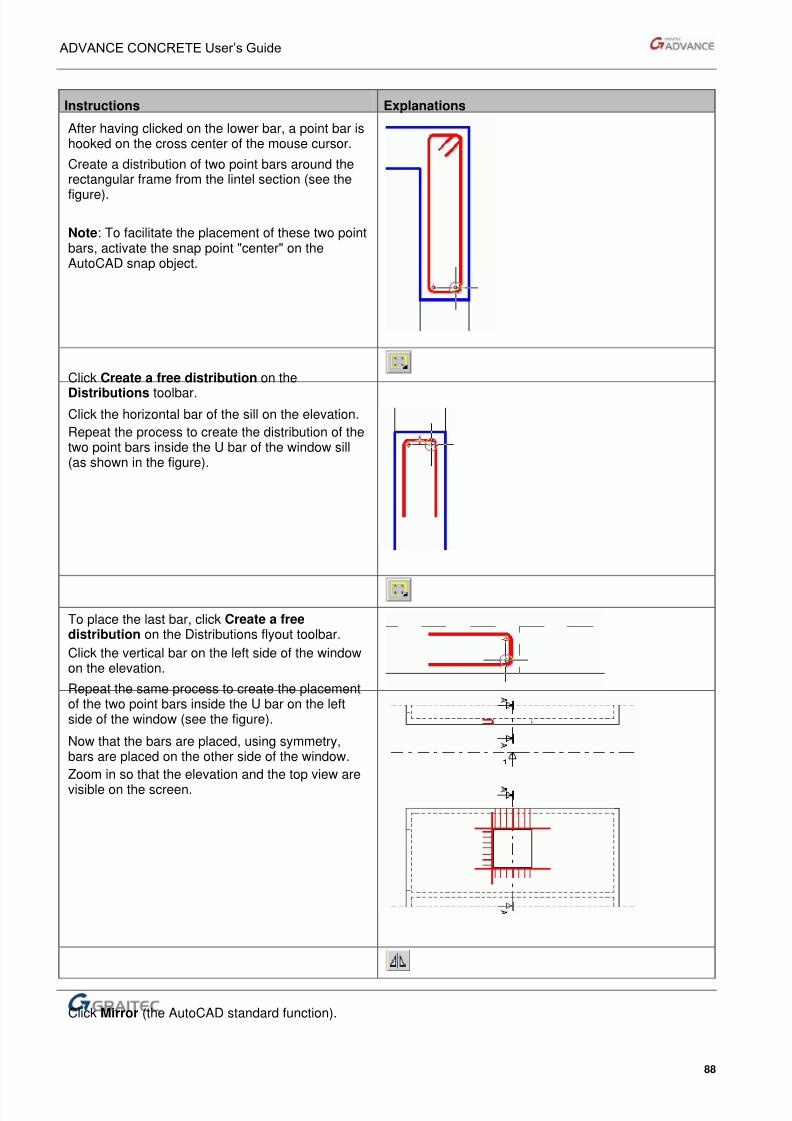
8/3/2019 AC UserGuide 2011 en Metric
http://slidepdf.com/reader/full/ac-userguide-2011-en-metric 88/114
ADVANCE CONCRETE User’s Guide
88
Instructions Explanations
After having clicked on the lower bar, a point bar ishooked on the cross center of the mouse cursor.
Create a distribution of two point bars around therectangular frame from the lintel section (see the
figure).
Note: To facilitate the placement of these two pointbars, activate the snap point "center" on theAutoCAD snap object.
Click Create a free distribution on the
Distributions toolbar.
Click the horizontal bar of the sill on the elevation.
Repeat the process to create the distribution of thetwo point bars inside the U bar of the window sill(as shown in the figure).
To place the last bar, click Create a freedistribution on the Distributions flyout toolbar.
Click the vertical bar on the left side of the windowon the elevation.
Repeat the same process to create the placementof the two point bars inside the U bar on the leftside of the window (see the figure).
Now that the bars are placed, using symmetry,bars are placed on the other side of the window.
Zoom in so that the elevation and the top view are
visible on the screen.
Click Mirror (the AutoCAD standard function).
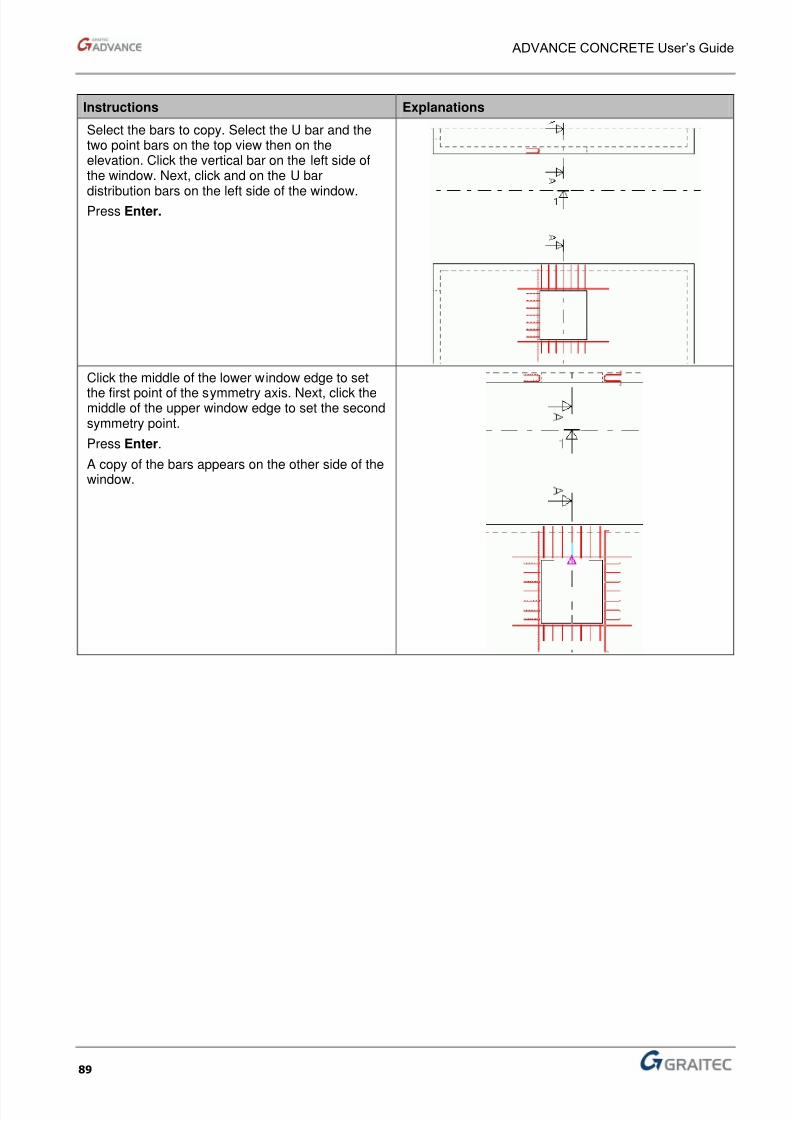
8/3/2019 AC UserGuide 2011 en Metric
http://slidepdf.com/reader/full/ac-userguide-2011-en-metric 89/114
ADVANCE CONCRETE User’s Guide
89
Instructions Explanations
Select the bars to copy. Select the U bar and thetwo point bars on the top view then on theelevation. Click the vertical bar on the left side ofthe window. Next, click and on the U bar
distribution bars on the left side of the window.Press Enter.
Click the middle of the lower window edge to set
the first point of the symmetry axis. Next, click themiddle of the upper window edge to set the secondsymmetry point.
Press Enter.
A copy of the bars appears on the other side of thewindow.

8/3/2019 AC UserGuide 2011 en Metric
http://slidepdf.com/reader/full/ac-userguide-2011-en-metric 90/114
ADVANCE CONCRETE User’s Guide
90
Step 4: View the reinforcement in 3D
In this step you will learn to view the reinforcement elements in a 3D view.
Instructions Explanations
Display the Advance Reinforcement 3D Viewer toolbar.Right-click the Advance Reinforcement toolbar and selectAdvance Reinforcement 3D Viewer.
The first step consists in selecting the 2D drawings in theviews.
Click Select and define the view.
Include the left view within a selection window and pressEnter.
On the definition window: the left side view is selected.
Click Next.
Include the top view within a selection window and pressEnter.
On the definition window: the upper view is selected.
Click Next.

8/3/2019 AC UserGuide 2011 en Metric
http://slidepdf.com/reader/full/ac-userguide-2011-en-metric 91/114
ADVANCE CONCRETE User’s Guide
91
Instructions Explanations
Finally, select the elevation and press Enter.
On the definition window: the elevation is selected.
Click Finish.
Click Start 3D viewer.
Preview the reinforcement in 3D view.
Also, you can view only the distribution of a bar. Click Start 3Dviewer.
Click on the bar to view (for example the frame).
Press Enter. Press Enter

8/3/2019 AC UserGuide 2011 en Metric
http://slidepdf.com/reader/full/ac-userguide-2011-en-metric 92/114
ADVANCE CONCRETE User’s Guide
92
Place reference marks on the distribution bars
Step 5: Place reference marks and dimensions on the distribution bars.
The fifth step explains how to place reference marks and dimensions on distribution bars.
Instructions Explanations
The first step consists of placing the bar reference marks onthe wall cut.
Zoom in on the lintel section.
On the Reinforcement symbols toolbar, click Create a barsymbol.
Click the rectangular frame and place the reference marknearby.
Click Create a bar symbol.
Click one of the two point bars and place the referencemarks.
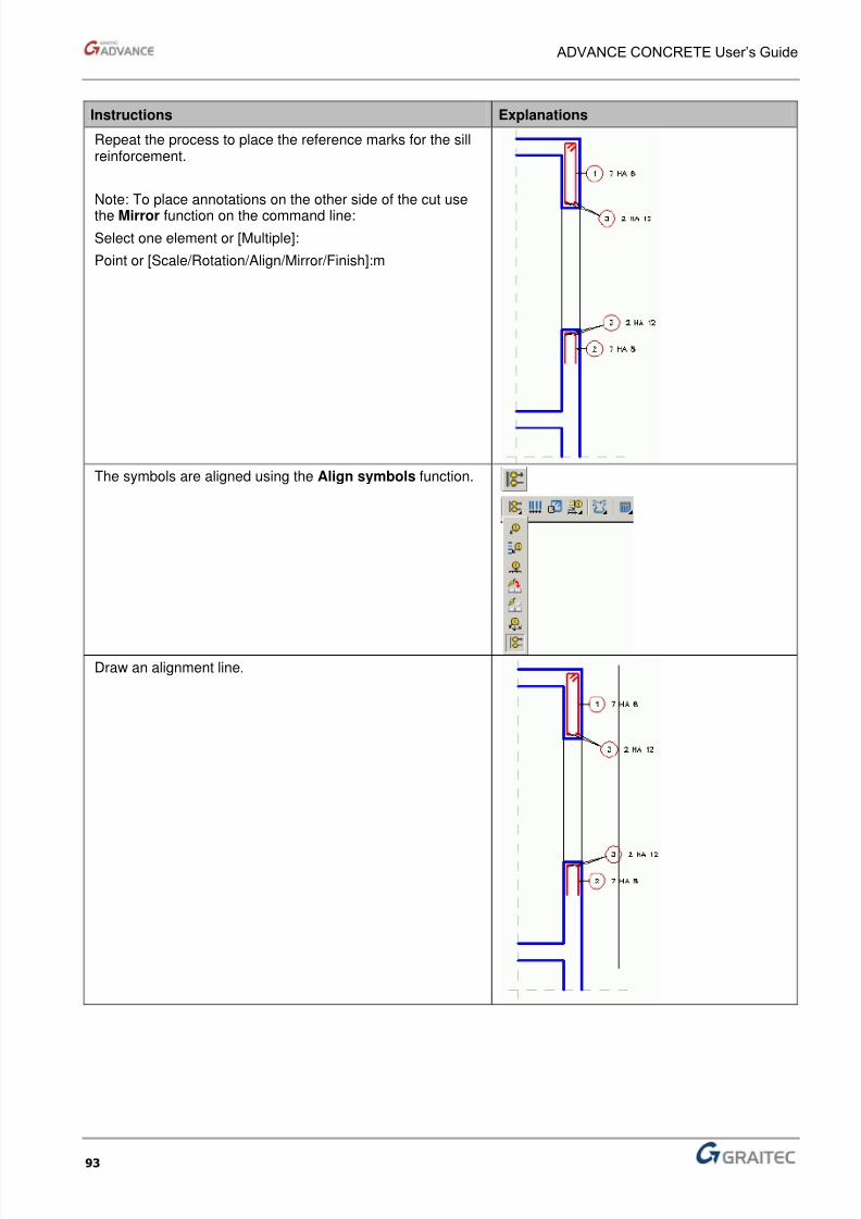
8/3/2019 AC UserGuide 2011 en Metric
http://slidepdf.com/reader/full/ac-userguide-2011-en-metric 93/114
ADVANCE CONCRETE User’s Guide
93
Instructions Explanations
Repeat the process to place the reference marks for the sillreinforcement.
Note: To place annotations on the other side of the cut use
the Mirror function on the command line:
Select one element or [Multiple]:
Point or [Scale/Rotation/Align/Mirror/Finish]:m
The symbols are aligned using the Align symbols function.
Draw an alignment line.
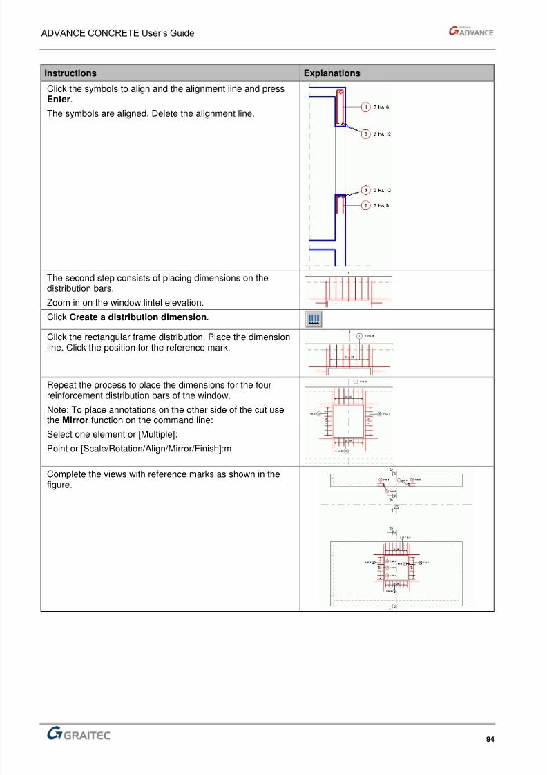
8/3/2019 AC UserGuide 2011 en Metric
http://slidepdf.com/reader/full/ac-userguide-2011-en-metric 94/114
ADVANCE CONCRETE User’s Guide
94
Instructions Explanations
Click the symbols to align and the alignment line and pressEnter.
The symbols are aligned. Delete the alignment line.
The second step consists of placing dimensions on thedistribution bars.
Zoom in on the window lintel elevation.
Click Create a distribution dimension.
Click the rectangular frame distribution. Place the dimensionline. Click the position for the reference mark.
Repeat the process to place the dimensions for the fourreinforcement distribution bars of the window.
Note: To place annotations on the other side of the cut usethe Mirror function on the command line:
Select one element or [Multiple]:
Point or [Scale/Rotation/Align/Mirror/Finish]:m
Complete the views with reference marks as shown in thefigure.
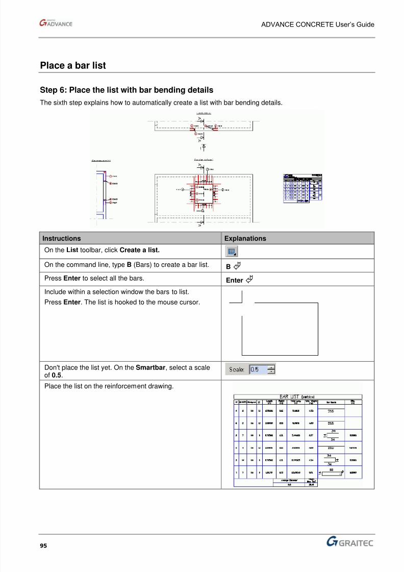
8/3/2019 AC UserGuide 2011 en Metric
http://slidepdf.com/reader/full/ac-userguide-2011-en-metric 95/114

8/3/2019 AC UserGuide 2011 en Metric
http://slidepdf.com/reader/full/ac-userguide-2011-en-metric 96/114
ADVANCE CONCRETE User’s Guide
96
Place the meshes
Step 7: Place meshes on the wall sides
The seventh step explains how to use the mesh library and how to place meshes on the wall sides.
Instructions Explanations
Zoom in on the wall elevation.
Click Create a mesh outline.
On the command line, type D (automatic Detection) tocreate the mesh outline by automatic detection.
D
Click inside the wall.
Now you have to cut the meshes for the window opening.Type Y (Yes ) on the command line and press Enter. Y
On the command line, type again D (automaticDetection) to define an opening in the mesh outline.
D
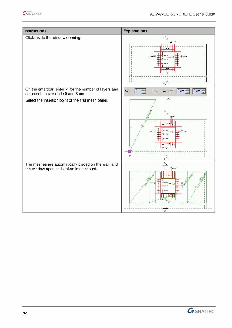
8/3/2019 AC UserGuide 2011 en Metric
http://slidepdf.com/reader/full/ac-userguide-2011-en-metric 97/114
ADVANCE CONCRETE User’s Guide
97
Instructions Explanations
Click inside the window opening.
On the smartbar, enter 2 for the number of layers anda concrete cover of de 0 and 3 cm.
Select the insertion point of the first mesh panel.
The meshes are automatically placed on the wall, andthe window opening is taken into account.

8/3/2019 AC UserGuide 2011 en Metric
http://slidepdf.com/reader/full/ac-userguide-2011-en-metric 98/114
ADVANCE CONCRETE User’s Guide
98
Place a mesh list
Step 8: Place the mesh list
The eighth and final step explains how to automatically create a meshes list.
Instructions Explanations
On the List toolbar, click Create a list.
On the Smartbar, select the Mesh details list.
On the command line, type F (fabrics) to create amesh list.
F and press Enter.
Then press Enter to select the meshes on thescreen.
Enter
Click the meshes to list.
Press Enter. The list is hooked to the mouse cursor.
Don't place the list yet. On the Smartbar, select ascale of 0.5.
Place the mesh list next to the reinforcementdrawing.
End of example.

8/3/2019 AC UserGuide 2011 en Metric
http://slidepdf.com/reader/full/ac-userguide-2011-en-metric 99/114
AppendicesCommand line
In this Chapter
■ Advance commands
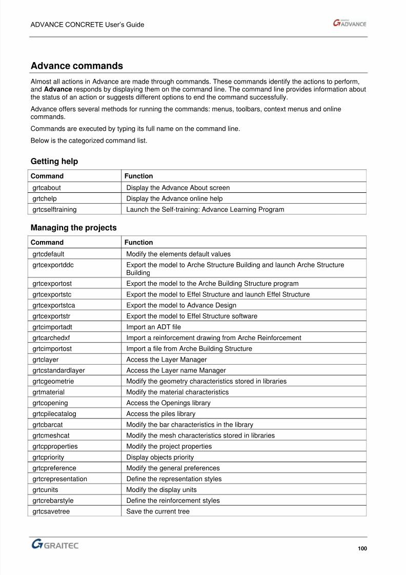
8/3/2019 AC UserGuide 2011 en Metric
http://slidepdf.com/reader/full/ac-userguide-2011-en-metric 100/114
ADVANCE CONCRETE User’s Guide
100
Advance commands
Almost all actions in Advance are made through commands. These commands identify the actions to perform,and Advance responds by displaying them on the command line. The command line provides information about
the status of an action or suggests different options to end the command successfully.Advance offers several methods for running the commands: menus, toolbars, context menus and onlinecommands.
Commands are executed by typing its full name on the command line.
Below is the categorized command list.
Getting help
Command Function
grtcabout Display the Advance About screen
grtchelp Display the Advance online helpgrtcselftraining Launch the Self-training: Advance Learning Program
Managing the projects
Command Function
grtcdefault Modify the elements default values
grtcexportddc Export the model to Arche Structure Building and launch Arche StructureBuilding
grtcexportost Export the model to the Arche Building Structure program
grtcexportstc Export the model to Effel Structure and launch Effel Structure
grtcexportstca Export the model to Advance Design
grtcexportstr Export the model to Effel Structure software
grtcimportadt Import an ADT file
grtcarchedxf Import a reinforcement drawing from Arche Reinforcement
grtcimportost Import a file from Arche Building Structure
grtclayer Access the Layer Manager
grtcstandardlayer Access the Layer name Manager
grtcgeometrie Modify the geometry characteristics stored in libraries
grtmaterial Modify the material characteristics
grtcopening Access the Openings librarygrtcpilecatalog Access the piles library
grtcbarcat Modify the bar characteristics in the library
grtcmeshcat Modify the mesh characteristics stored in libraries
grtcpproperties Modify the project properties
grtcpriority Display objects priority
grtcpreference Modify the general preferences
grtcrepresentation Define the representation styles
grtcunits Modify the display units
grtcrebarstyle Define the reinforcement stylesgrtcsavetree Save the current tree
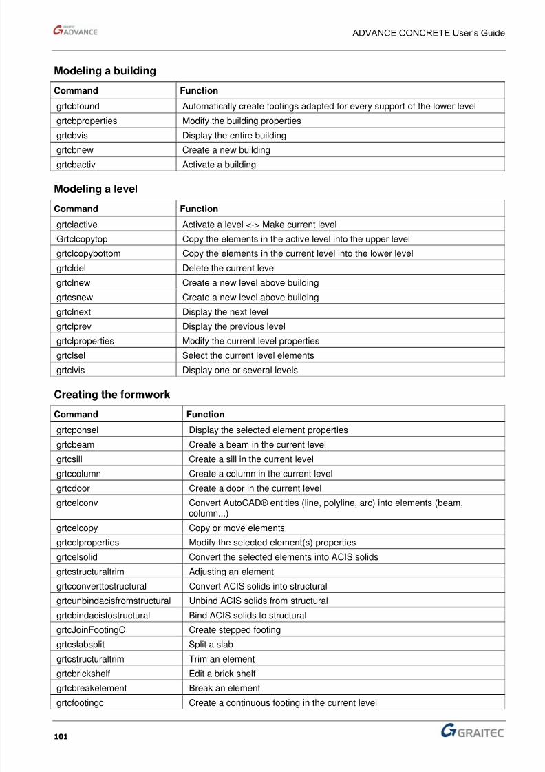
8/3/2019 AC UserGuide 2011 en Metric
http://slidepdf.com/reader/full/ac-userguide-2011-en-metric 101/114
ADVANCE CONCRETE User’s Guide
101
Modeling a building
Command Function
grtcbfound Automatically create footings adapted for every support of the lower level
grtcbproperties Modify the building properties
grtcbvis Display the entire building
grtcbnew Create a new building
grtcbactiv Activate a building
Modeling a level
Command Function
grtclactive Activate a level <-> Make current level
Grtclcopytop Copy the elements in the active level into the upper level
grtclcopybottom Copy the elements in the current level into the lower level
grtcldel Delete the current levelgrtclnew Create a new level above building
grtcsnew Create a new level above building
grtclnext Display the next level
grtclprev Display the previous level
grtclproperties Modify the current level properties
grtclsel Select the current level elements
grtclvis Display one or several levels
Creating the formwork
Command Function
grtcponsel Display the selected element properties
grtcbeam Create a beam in the current level
grtcsill Create a sill in the current level
grtccolumn Create a column in the current level
grtcdoor Create a door in the current level
grtcelconv Convert AutoCAD® entities (line, polyline, arc) into elements (beam,column...)
grtcelcopy Copy or move elements
grtcelproperties Modify the selected element(s) properties
grtcelsolid Convert the selected elements into ACIS solids
grtcstructuraltrim Adjusting an element
grtcconverttostructural Convert ACIS solids into structural
grtcunbindacisfromstructural Unbind ACIS solids from structural
grtcbindacistostructural Bind ACIS solids to structural
grtcJoinFootingC Create stepped footing
grtcslabsplit Split a slab
grtcstructuraltrim Trim an element
grtcbrickshelf Edit a brick shelfgrtcbreakelement Break an element
grtcfootingc Create a continuous footing in the current level

8/3/2019 AC UserGuide 2011 en Metric
http://slidepdf.com/reader/full/ac-userguide-2011-en-metric 102/114
ADVANCE CONCRETE User’s Guide
102
Command Function
grtcfootingi Create an isolated footing in the current level
grtcbeddingi Create a bedding isolated footing in the current level
grtcfootingc Create a bedding continuous footing in the current level
grtcpile Create a pile in the current levelgrtcpileproperties Modify the pile properties
grtcpile Create a drill depth area in the current level
grtclintel Create a lintel in the current level
grtcpolyopening Create a polygonal opening in the current level
grtcbeamreservationline Create a beam openings line in the current level
grtcslab Create a slab in the current level
grtcstdopening Create an opening or a depression in the current level
grtcwall Create a wall in the current level
grtcwindow Create a window in the current level
grtcroof Create a roof or a sloped shape
grtcroofproperties Modify selected roof properties
grtcbindstructurals Bind the elements to the roof
grtcslope Create a slope in the current level
grtcstairs Create a stair in the current level
grtcprecaststairpbm Link to the PBM website (precast stairs)
grtcprecaststairb Link to the SB website (precast stairs)
grtcrenumbergrid Renumber the grid axes
grtcgrid Create a grid
Creating the reinforcement
Command Function
grtcshapebar Create a new bar shape
grtcpointbar Create a point bar
grtcstraightbar Create a straight bar
grtcetrier Create a stirrup bar
grtcrectbar Create a rectangular frame
grtccerce Create a circular bar
grtcpinbar Create a pin bargrtcubar Create a U bar
grtclbar Create an L bar
grtcpolbar Create a polygonal bar
grtcbreakbar Break a bar
grtceditbar Edit a bar
grtcrepartfree Create a free distribution
grtcrepartlinear Create a free linear distribution
grtcrepartvarlinear Create a free linear variable distribution
grtcrepartquantity Create a quantitative distribution
grtcrepartcut Create a cut distribution
grtcrepartone Create a one by one distribution
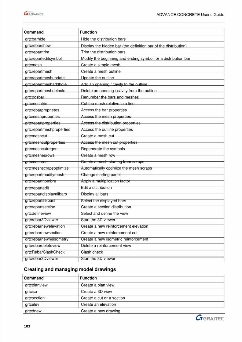
8/3/2019 AC UserGuide 2011 en Metric
http://slidepdf.com/reader/full/ac-userguide-2011-en-metric 103/114
ADVANCE CONCRETE User’s Guide
103
Command Function
grtcbarhide Hide the distribution bars
grtcrebarshow Display the hidden bar (the definition bar of the distribution)
grtcreparttrim Trim the distribution bars
grtcreparteditsymbol Modify the beginning and ending symbol for a distribution bargrtcmesh Create a simple mesh
grtcrepartmesh Create a mesh outline
grtcrepartmeshupdate Update the outline
grtcrepartmeshaddhole Add an opening / cavity to the outline
grtcrepartmeshdelhole Delete an opening / cavity from the outline
grtcposbar Renumber the bars and meshes
grtcmeshtrim Cut the mesh relative to a line
grtcrebarproprietes Access the bar properties
grtcmeshproperties Access the mesh properties
grtcrepartproperties Access the distribution properties
grtcrepartmeshproperties Access the outline properties
grtcmeshcut Create a mesh cut
grtcmeshcutproperties Access the mesh cut properties
grtcmeshcutregen Regenerate the symbols
grtcmeshesrows Create a mesh row
grtcmeshrest Create a mesh starting from scraps
grtcmeshscrapsoptimize Automatically optimize the mesh scraps
grtcrepartmodifymesh Change starting panel
grtcrepartnombre Apply a multiplication factor
grtcrepartedit Edit a distribution
grtcrepartdisplayallbars Display all bars
grtcrepartselbars Select the displayed bars
grtcrepartsection Create a section distribution
grtcdefineview Select and define the view
grtcrebar3Dviewer Start the 3D viewer
grtcrebarnewelevation Create a new reinforcement elevation
grtcrebarnewsection Create a new reinforcement cut
grtcrebarnewneisometry Create a new isometric reinforcementgrtcrebardeleteview Delete a reinforcement view
grtcRebarClashCheck Clash check
grtcrebar3Dviewer Start the 3D viewer
Creating and managing model drawings
Command Function
grtcplanview Create a plan view
grtciso Create a 3D view
grtcsection Create a cut or a sectiongrtcelev Create an elevation
grtcdnew Create a new drawing
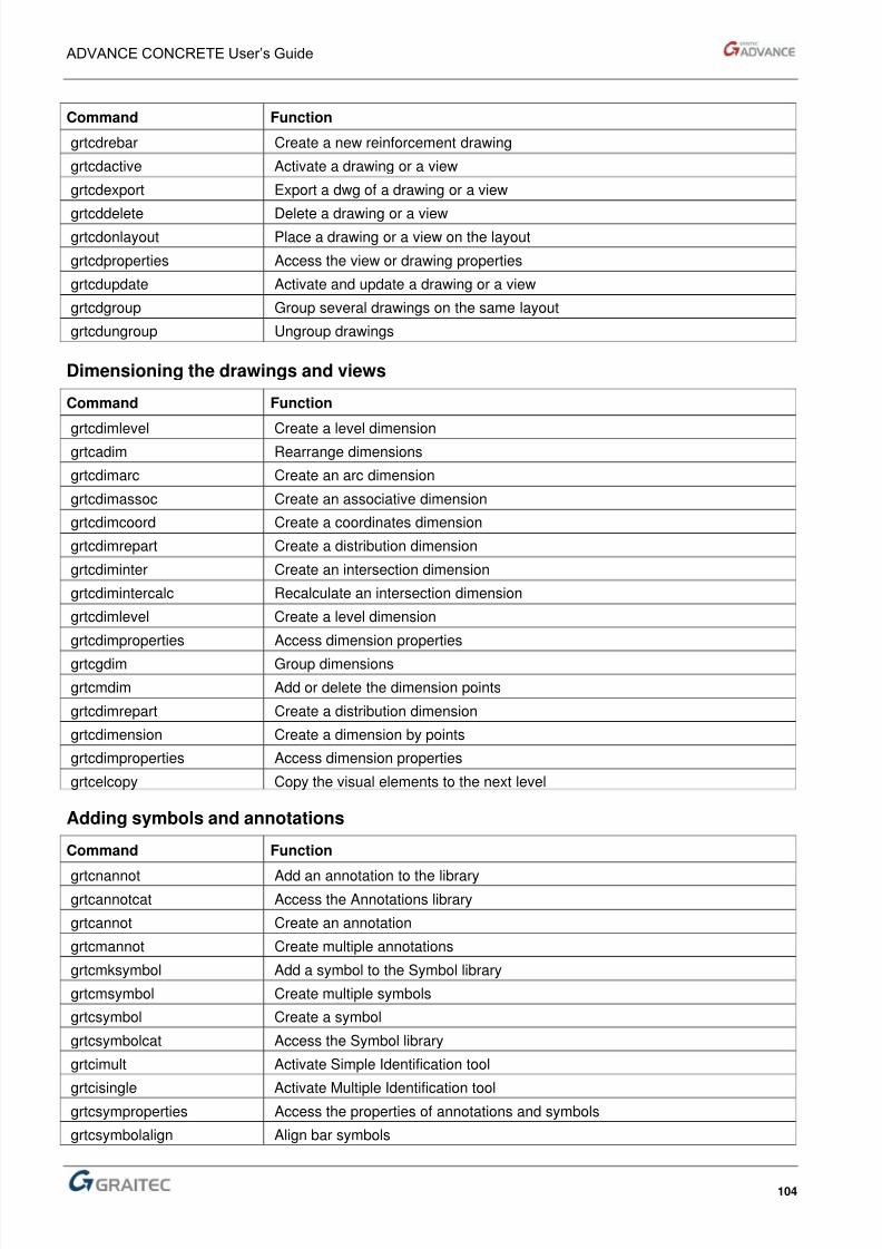
8/3/2019 AC UserGuide 2011 en Metric
http://slidepdf.com/reader/full/ac-userguide-2011-en-metric 104/114
ADVANCE CONCRETE User’s Guide
104
Command Function
grtcdrebar Create a new reinforcement drawing
grtcdactive Activate a drawing or a view
grtcdexport Export a dwg of a drawing or a view
grtcddelete Delete a drawing or a viewgrtcdonlayout Place a drawing or a view on the layout
grtcdproperties Access the view or drawing properties
grtcdupdate Activate and update a drawing or a view
grtcdgroup Group several drawings on the same layout
grtcdungroup Ungroup drawings
Dimensioning the drawings and views
Command Function
grtcdimlevel Create a level dimension
grtcadim Rearrange dimensions
grtcdimarc Create an arc dimension
grtcdimassoc Create an associative dimension
grtcdimcoord Create a coordinates dimension
grtcdimrepart Create a distribution dimension
grtcdiminter Create an intersection dimension
grtcdimintercalc Recalculate an intersection dimension
grtcdimlevel Create a level dimension
grtcdimproperties Access dimension properties
grtcgdim Group dimensions
grtcmdim Add or delete the dimension points
grtcdimrepart Create a distribution dimension
grtcdimension Create a dimension by points
grtcdimproperties Access dimension properties
grtcelcopy Copy the visual elements to the next level
Adding symbols and annotations
Command Function
grtcnannot Add an annotation to the library
grtcannotcat Access the Annotations library
grtcannot Create an annotation
grtcmannot Create multiple annotations
grtcmksymbol Add a symbol to the Symbol library
grtcmsymbol Create multiple symbols
grtcsymbol Create a symbol
grtcsymbolcat Access the Symbol library
grtcimult Activate Simple Identification tool
grtcisingle Activate Multiple Identification toolgrtcsymproperties Access the properties of annotations and symbols
grtcsymbolalign Align bar symbols
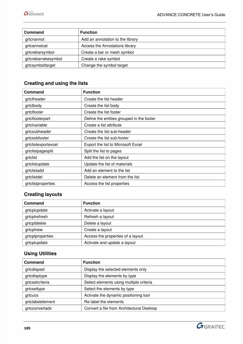
8/3/2019 AC UserGuide 2011 en Metric
http://slidepdf.com/reader/full/ac-userguide-2011-en-metric 105/114

8/3/2019 AC UserGuide 2011 en Metric
http://slidepdf.com/reader/full/ac-userguide-2011-en-metric 106/114

8/3/2019 AC UserGuide 2011 en Metric
http://slidepdf.com/reader/full/ac-userguide-2011-en-metric 107/114
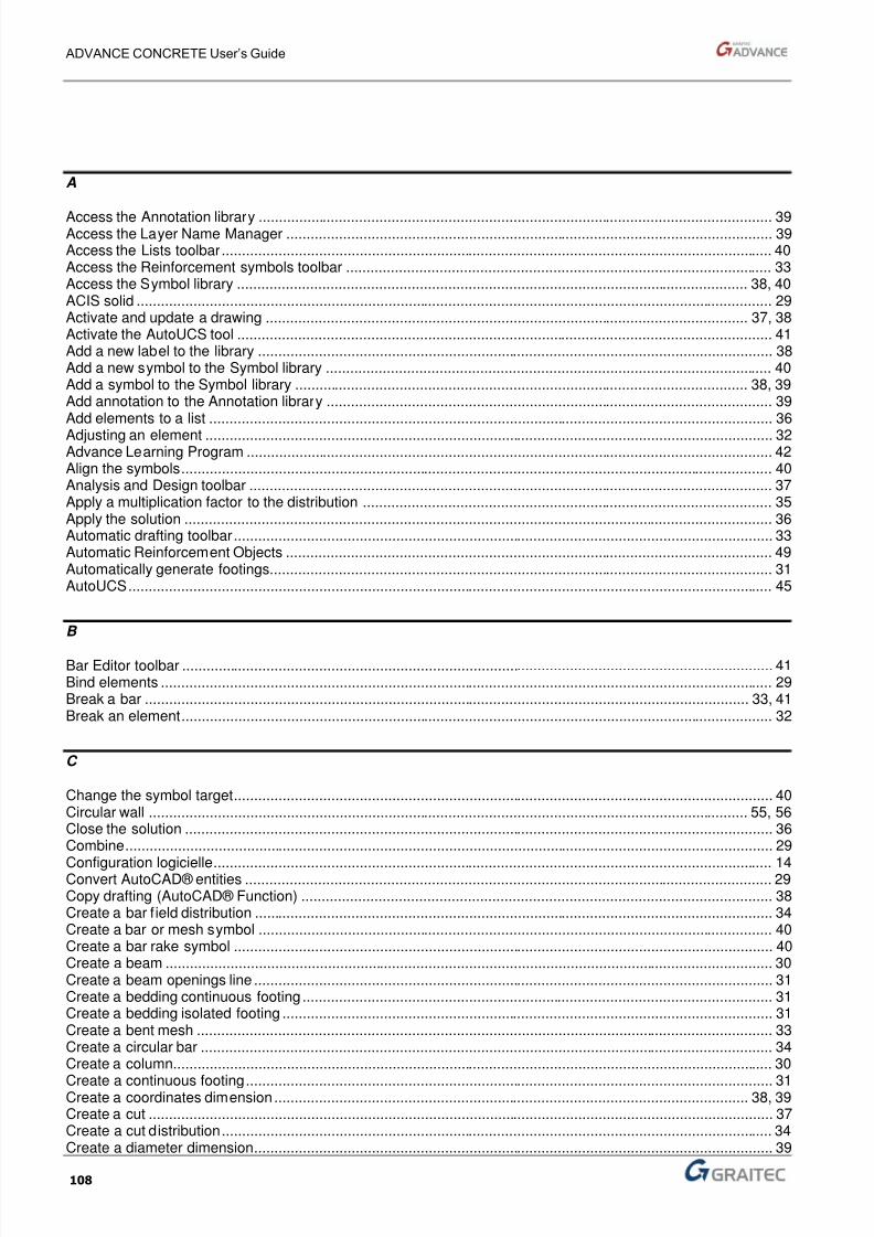
8/3/2019 AC UserGuide 2011 en Metric
http://slidepdf.com/reader/full/ac-userguide-2011-en-metric 108/114
ADVANCE CONCRETE User’s Guide
108
A Access the Annotation library ............................................................................................................................... 39Access the Layer Name Manager ........................................................................................................................ 39Access the Lists toolbar ........................................................................................................................................ 40Access the Reinforcement symbols toolbar ......................................................................................................... 33Access the Symbol library .............................................................................................................................. 38, 40ACIS solid ............................................................................................................................................................. 29Activate and update a drawing ....................................................................................................................... 37, 38Activate the AutoUCS tool .................................................................................................................................... 41Add a new label to the library ............................................................................................................................... 38Add a new symbol to the Symbol library .............................................................................................................. 40Add a symbol to the Symbol library ................................................................................................................ 38, 39Add annotation to the Annotation library .............................................................................................................. 39Add elements to a list ........................................................................................................................................... 36
Adjusting an element ............................................................................................................................................ 32Advance Learning Program .................................................................................................................................. 42Align the symbols .................................................................................................................................................. 40Analysis and Design toolbar ................................................................................................................................. 37Apply a multiplication factor to the distribution ..................................................................................................... 35Apply the solution ................................................................................................................................................. 36Automatic drafting toolbar ..................................................................................................................................... 33Automatic Reinforcement Objects ........................................................................................................................ 49Automatically generate footings............................................................................................................................ 31AutoUCS ............................................................................................................................................................... 45
B Bar Editor toolbar .................................................................................................................................................. 41Bind elements ....................................................................................................................................................... 29Break a bar ..................................................................................................................................................... 33, 41Break an element .................................................................................................................................................. 32
C Change the symbol target ..................................................................................................................................... 40Circular wall .................................................................................................................................................... 55, 56Close the solution ................................................................................................................................................. 36Combine ................................................................................................................................................................ 29
Configuration logicielle .......................................................................................................................................... 14Convert AutoCAD® entities .................................................................................................................................. 29Copy drafting (AutoCAD® Function) .................................................................................................................... 38Create a bar field distribution ................................................................................................................................ 34Create a bar or mesh symbol ............................................................................................................................... 40Create a bar rake symbol ..................................................................................................................................... 40Create a beam ...................................................................................................................................................... 30Create a beam openings line ................................................................................................................................ 31Create a bedding continuous footing .................................................................................................................... 31Create a bedding isolated footing ......................................................................................................................... 31Create a bent mesh .............................................................................................................................................. 33Create a circular bar ............................................................................................................................................. 34Create a column.................................................................................................................................................... 30
Create a continuous footing .................................................................................................................................. 31Create a coordinates dimension ..................................................................................................................... 38, 39Create a cut .......................................................................................................................................................... 37Create a cut distribution ........................................................................................................................................ 34Create a diameter dimension ................................................................................................................................ 39

8/3/2019 AC UserGuide 2011 en Metric
http://slidepdf.com/reader/full/ac-userguide-2011-en-metric 109/114

8/3/2019 AC UserGuide 2011 en Metric
http://slidepdf.com/reader/full/ac-userguide-2011-en-metric 110/114
ADVANCE CONCRETE User’s Guide
110
Create multiple labels ........................................................................................................................................... 38Create multiple symbols ................................................................................................................................. 38, 39Create stepped footing ......................................................................................................................................... 32
D Define a solution ................................................................................................................................................... 36Delete a reinforcement view ................................................................................................................................. 35Delete elements from a list ................................................................................................................................... 36Dimensions toolbar ............................................................................................................................................... 38Display elements by type ...................................................................................................................................... 41Display next level .................................................................................................................................................. 30Display previous level ........................................................................................................................................... 30Display the bar definition ...................................................................................................................................... 34Display the hidden element .................................................................................................................................. 35Display the Symbol library .................................................................................................................................... 39Displaying objects by type .................................................................................................................................... 49Distribution Editor toolbar ..................................................................................................................................... 35
Distribution toolbar ................................................................................................................................................ 33Distributions toolbar .............................................................................................................................................. 34Documents ...................................................................................................................................................... 22, 43Documents toolbar ................................................................................................................................................ 40Doors and Windows manager .............................................................................................................................. 48Drawings ............................................................................................................................................................... 43Drawings toolbar ............................................................................................................................................. 29, 37
E Edit a bar ............................................................................................................................................................... 41Edit a brick shelf.................................................................................................................................................... 32Edit a distribution .................................................................................................................................................. 35Edit distribution toolbar ......................................................................................................................................... 33Export a list to Excel ............................................................................................................................................. 36Export to Advance Design .................................................................................................................................... 37Export to Arche Building Structure........................................................................................................................ 37Export to Effel Structure ........................................................................................................................................ 37Export to GTC ....................................................................................................................................................... 42Export to IFC ......................................................................................................................................................... 42
F Formwork Functions toolbar ................................................................................................................................. 32Foundations toolbar ........................................................................................................................................ 29, 31
G Graitec Transfer Center toolbar ............................................................................................................................ 42Grid toolbar ..................................................................................................................................................... 29, 30
H Help ....................................................................................................................................................................... 43Help Toolbar ......................................................................................................................................................... 42Hide the bar definition ........................................................................................................................................... 34
Hide the selected elements .................................................................................................................................. 41

8/3/2019 AC UserGuide 2011 en Metric
http://slidepdf.com/reader/full/ac-userguide-2011-en-metric 111/114
ADVANCE CONCRETE User’s Guide
111
I Import a drawing .................................................................................................................................................... 37Import from IFC ...................................................................................................................................................... 42Import to GTC ........................................................................................................................................................ 42Import-Export standard files toolbar ...................................................................................................................... 42
Insert dynamic block ........................................................................................................................................39, 41Isolate the selected elements ................................................................................................................................ 41
L Lancer la visualisation 3D ...................................................................................................................................... 35Launch the Multiple Identification tool ................................................................................................................... 41Launch the Simple Identification tool ..................................................................................................................... 41Layer Name Manager ............................................................................................................................................ 29Levels toolbar ........................................................................................................................................................ 30Lists toolbar .....................................................................................................................................................33, 36
M Material Manager ................................................................................................................................................... 46Material quantities management ........................................................................................................................... 29Meshes Scraps toolbar .......................................................................................................................................... 33Model ..................................................................................................................................................................... 43Move elements ...................................................................................................................................................... 29Multicriteria object selection................................................................................................................................... 49
O Object Geometry Manager .................................................................................................................................... 47
Object snap ............................................................................................................................................................ 55Openings toolbar .............................................................................................................................................29, 31
P Pilot ................................................................. 20, 21, 22, 29, 38, 43, 44, 53, 62, 64, 66, 70, 71, 72, 73, 74, 75, 76Print layouts ........................................................................................................................................................... 40Project .................................................................................................................................................................... 43
R Reinforcement ....................................................................................................................................................... 43Reinforcement 3D Viewer toolbar .......................................................................................................................... 35Reinforcement Bars toolbar .............................................................................................................................32, 34Reinforcement renumbering toolbar ...................................................................................................................... 33Reinforcement Renumbering toolbar ..................................................................................................................... 34Reinforcement Solutions toolbar ........................................................................................................................... 36Reinforcement Symbols toolbar ............................................................................................................................ 40Reinforcement toolbar ........................................................................................................................................... 32Re-label elements .................................................................................................................................................. 41Roofs and Ramps toolbar ...................................................................................................................................... 29
S Save the solution ................................................................................................................................................... 36Select and define the view ..................................................................................................................................... 35Select elements by type......................................................................................................................................... 41Select elements using multiple criteria .................................................................................................................. 41

8/3/2019 AC UserGuide 2011 en Metric
http://slidepdf.com/reader/full/ac-userguide-2011-en-metric 112/114
ADVANCE CONCRETE User’s Guide
112
Shortcut Access Menu .......................................................................................................................................... 44Sketch Designer toolbar ....................................................................................................................................... 35Smartbar ......................................................................................................................................................... 27, 57Solution multiplication factor ................................................................................................................................. 36Solution visibility properties .................................................................................................................................. 36Split a slab ............................................................................................................................................................ 32
Split into pages ..................................................................................................................................................... 36Stairs toolbar ................................................................................................................................................... 29, 32Start the 3D viewer ............................................................................................................................................... 35Start the online help .............................................................................................................................................. 42Structural toolbar .................................................................................................................................................. 29Synchronize data with an Arche Structure file ...................................................................................................... 37Syncronize with GTC ............................................................................................................................................ 42
T Tools ..................................................................................................................................................................... 43Tools toolbar ......................................................................................................................................................... 41
Tooltips ................................................................................................................................................................. 46Trim one or several meshes ................................................................................................................................. 33Trim the distribution bars ...................................................................................................................................... 35
U Update a list .......................................................................................................................................................... 36Update layout ........................................................................................................................................................ 40Update solutions references ................................................................................................................................. 36
V View the label library ............................................................................................................................................. 38Views Toolbar ....................................................................................................................................................... 38Visual elements..................................................................................................................................................... 43

8/3/2019 AC UserGuide 2011 en Metric
http://slidepdf.com/reader/full/ac-userguide-2011-en-metric 113/114
8/3/2019 AC UserGuide 2011 en Metric
http://slidepdf.com/reader/full/ac-userguide-2011-en-metric 114/114
Canada
GRAITEC Inc.
183, St. Charles St. W.Suite 300Longueuil (Québec) CanadaJ4H1C8
Tel. (450) 674-0657Fax (450) 674-0665Hotline (450) 674-0657Toll free 1-800-724-5678Web http://www.graitec.com/En/ Email [email protected]
France
GRAITEC France Sarl
17 Burospace91573 Bièvres CedexTel. 33 (0)1 69 85 56 22Fax 33 (0)1 69 85 33 70
Web http://www.graitec.com/Fr/ Email [email protected]
Germany, Switzerland, Austria
GRAITEC GmbH
Centroallee 263aD-46047 Oberhausen GermanyTel. +49-(0) 208 / 62188-0
Fax +49-(0) 208 / 62188-29Web http://www.graitec.com/Ge/ Email [email protected]
Czech Republic and Slovakia
AB Studio spol. s r.o.
Jeremenkova 90a 140 00 PRAHA 4Tel. +420/244 016 055Fax +420/244 016 088
Hotline +420/244 016 050Web http://www.abstudio.cz/ Email [email protected]
United Kingdom
GRAITEC UK Ltd.
The Old ForgeSuth RoadWeybridgeSurrey KT13 9DZTel. +44 (0)1932 858516Fax +44 (0)1932 859099Email [email protected]
Russia
GRAITEC CJSC
Dmitrovskoe shosse, 60AMoscow 127474Tel. +7(495) 225-13-65Fax. +7(495) 225-13-65Email [email protected]
Romania
GRAITEC Roumanie SRL
Str. Samuil Vulcan, Nr. 10 Sector 5Bucureşti, Romania Tel. +40 (21) 410 0119Fax +40 (21) 410 0124Mobile 0729 002 107Web http://www graitec com/Ro/