Embed Size (px)
Citation preview

7/28/2019 AE1310
http://slidepdf.com/reader/full/ae1310 1/12
1© 2010 Emerson Climate Technologies
Printed in the U.S.A.
AE4A-1310 R1
Application Engineering
B U L L E T I N
Application Guidelines for Glacier K4 RefrigerationHorizontal Scroll Compressors 2 - 6 Horsepower
AE4-1310 R1 December 2000Reformatted October 2010
Application Engineering
B U L L E T I N
Introduction
The Horizontal ZFH/ZSH*K4 scroll compressor utilizesthe current technology as the standard vertical K4offerings and incorporates the inherent features listedbelow in the five bullet points.
• Scroll orientation technology - Specifically designedto achieve the higher compression ratios typicallyfound in refrigeration applications
• Addition of Dynamic Discharge valve - Providesimproved energy ef ficiency when operating at highcompression ratio conditions
• Modified Injection System - Enables the Scroll toaccept liquid injection depending on system design
• DU Drive Bearing - This Teflon impregnated bronzebearing provides improved reliability
• Positive Displacement Oil Pump - Internallubrication for the compressor is achieved by meansof a positive displacement oil pump
These changes result in a compressor that is suit-ablefor the most demanding refrigeration applications withef ficiencies comparable to the industry standard Discus® compressor.
Nomenclature
The Glacier TM Scroll model numbers include the nominalcapacity at standard 60Hz ARI rating conditions. Pleaserefer to product literature for model number details.
Operating Envelope
Horizontal Glacier TM K4 Models can be used with avariety of refrigerants depending on the model selectedand the lubricant used: See Table 1.
Table 1
Model Refrigerant Lubricant
ZFH R-22 MO
ZFH R-404A, R-507, R-22 POE
ZSH R-404A, R-507 POE
ZSH R-22 POE/MO
See AE17-1248 for a complete list of all Emersonapproved lubricants.
The ZFH and ZSH model families are intended for refrigeration type duty. The approved operatingenvelopes for these models are depicted in Figures3A through 3D.
It must be noted that the ZFH model when operated atlow evaporator temperatures requires liquid injectionto prevent overheating of the compressor scrollmechanism.
Liquid Injection
The low temperature Scroll compressor is provided withan injection port suitable for connection to a source of liquid refrigerant. Internally, this port is connected to aninner pocket of the scroll mechanism. Since this pocketis separated from the suction inlet, no loss of capacityor mass flow results from injecting at this point.
For the liquid injection system to be effective, a minimumof 5°F sub-cooled liquid at the DTC Valve inlet is
required.Liquid Injection Discharge Temperature ControlValve
The DTC is required on the 2 through 6 HP ZFHGlacier scroll model family for all applications that needliquid injection and is approved to be applied with allrefrigerants.
Figure 4 is a representation of a typical system for liquid injection.
Valve Specifications
Opening Set Point: 193°F ±5°F (116°C ±3°C)
Liquid Line Connection: 3/8” (9.5mm)
The maximum operating temperature of the valve
sensing bulb is limited to 293°F.
Installation of Valve
The valve bulb must be installed in the end cap thermalwell to adequately control scroll temperatures. The valveshould be tightened on the injection fitting to a torque of 216-245 in. lbs. (24.4 - 27.7 Nm). A 90 degree orientation

7/28/2019 AE1310
http://slidepdf.com/reader/full/ae1310 2/12
2© 2010 Emerson Climate Technologies
Printed in the U.S.A.
AE4A-1310 R1
Application Engineering
B U L L E T I N
on the valve is recommended, however it will functionproperly in any orientation. The capillary tube connectingthe valve to the bulb should be positioned such that itdoes not contact the compressor during operation. Donot bend the capillary tube within 1” (25.4mm) of thevalve.
The DTC Valve comes with an insulating cap. If thisadditional length from the cap is an issue, the valvecap could be replaced with high temperature insulation.This should be applied to insulate and protect the valve.This will reduce the total length requirement by 0.5”(12.7mm). See Figure 5.
Suggested Application Techniques
For the most ef ficient heat transfer, spread a thin filmof thermal grease around the DTC Valve bulb beforeinstalling into the end cap well. This is not required,
however, for proper functioning of the valve.
At your discretion, field serviceability can be improvedby installing a shut-off valve in the liquid line just beforethe DTC Valve.
The valve requires a solid column of liquid duringoperation and at startup. A liquid line sightglass couldbe applied to visually insure liquid flow.
Compressor Or Valve Service
Replacing a ZFH compressor using the DTC Valve:
We recommend replacing both the DTC Valve and thecompressor at the same time. If you wish to use the
existing DTC Valve, the valvefilter (pn 013-0119-00)should be cleaned or replaced.
Replacing a DTC Valve on a ZFH compressor:
Before replacing the DTC Valve, clean or change thefilter to verify there is an unobstructed column of liquidto the valve.
Accumulators
Due to the Scroll’s inherent ability to handle liquidrefrigerant in flooded start and defrost cycle opeartionconditions, accumulators may not be required. Anaccumulator is required on single compressor systemswith charges over 10 lbs. On systems with defrostschemes or transient operations that allow prolonged,uncontrolled liquid return to the compressor, anaccumulator is required unless a suction header of suf ficient volume to prevent liquid migration to thecompressor is used.
Excessive liquid flood back or repeated flooded startswill dilute the oil in any compressor causing inadequatelubrication and bearing wear. Proper system design willminimize liquid flood back thereby ensuring maximumcompressor life.
Crankcase Heaters
• Single Phase - No crankcase heaters are requiredon single phase Horizontal Scroll compressors.
• Three Phase - Outdoor Only
Crankcase heaters are required on three phasecompressors when the system charge exceeds tenpounds. However, Copeland Engineering is currentlyworking to develop crankcase heaters for three phasehorizontal scroll compressors. As there are no partnumbers assigned at the time of printing, please contactCopeland Application Engineering if your applicationrequires a crankcase heater. If the heater is not conduitready, a terminal box may be required. Copeland
Application Engineering will discuss the need of aterminal box as the crankcase heaters are developed.
Table 2ACrankcase Heaters
Model Part No. Volts Watts
ZFH06, 09ZSH15, 21
TBD TBD TBD
ZFH06, 09ZSH15, 21
TBD TBD TBD
ZFH06, 09ZSH15, 21
TBD TBD TBD
ZFH06, 09ZSH15, 21
TBD TBD TBD
ZFH13, 15, 18ZSH30, 38, 45 TBD TBD TBD
ZFH13, 15, 18ZSH30, 38, 45
TBD TBD TBD
ZFH13, 15, 18ZSH30, 38, 45
TBD TBD TBD
ZFH13, 15, 18ZSH30, 38, 45
TBD TBD TBD
Table 2AConduit Ready Heater Terminal Box Kits
Models Part Number
ZFH06, 09ZSH15, 21
TBD
ZFH13, 15, 18ZSH30, 38, 45
TBD
7/28/2019 AE1310
http://slidepdf.com/reader/full/ae1310 3/12
3© 2010 Emerson Climate Technologies
Printed in the U.S.A.
AE4A-1310 R1
Application Engineering
B U L L E T I N
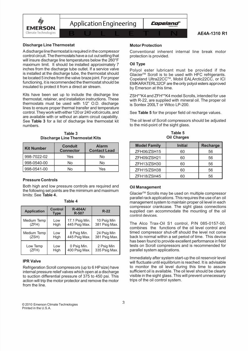
Discharge Line Thermostat
A discharge line thermostat is required in the compressor control circuit. The thermostats have a cut out setting that
will insure discharge line temperatures below the 260°Fmaximum limit. It should be installed approximately 7inches from the discharge tube outlet. If a service valveis installed at the discharge tube, the thermostat shouldbe located 5 inches from the valve braze joint. For proper functioning, it is recommended the thermostat should beinsulated to protect it from a direct air stream.
Kits have been set up to include the discharge linethermostat, retainer, and installation instructions. Thesethermostats must be used with 1/2” O.D. dischargelines to ensure proper thermal transfer and temperaturecontrol. They work with either 120 or 240 volt circuits, andare available with or without an alarm circuit capability.
See Table 3 for a list of discharge line thermostat kitnumbers.
Table 3Discharge Line Thermostat Kits
Kit Number Conduit
Connector Alarm
Contact Lead
998-7022-02 Yes No
998-0540-00 No No
998-0541-00 No Yes
Pressure Controls
Both high and low pressure controls are required andthe following set points are the mimimum and maximumlimits: See Table 4.
Table 4
ApplicationControl
TypeR-404A/R-507
R-22
Medium Temp(ZFH)
LowHigh
17.1 Psig Min.445 Psig Max.
10 Psig Min381 Psig Max.
Medium Temp(ZSH)
LowHigh
8 Psig Min.445 Psig Max.
24 Psig Min381 Psig Max.
Low Temp(ZFH)
LowHigh
0 Psig Min.400 Psig Max.
2 Psig Min335 Psig Max.
IPR Valve
Refrigeration Scroll compressors (up to 6 HP size) haveinternal pressure relief valves which open at a dischargeto suction differential pressure of 375 to 450 psi. Thisaction will trip the motor protector and remove the motor from the line.
Motor Protection
Conventional inherent internal line break motor protection is provided.
Oil Type
Polyol ester lubricant must be provided if theGlacier TM Scroll is to be used with HFC refrigerants.Copeland Ultra22CCTM, Mobil EALArctic22CC, or ICIEMKARATERL32CF are the only polyol esters approvedby Emerson at this time.
ZSH**K4 and ZFH**K4 model Scrolls, intended for usewith R-22, are supplied with mineral oil. The proper oilis Sontex 200LT or Witco LP-200.
See Table 5 for the proper field oil recharge values.
The oil level of Scroll compressors should be adjustedto the mid-point of the sight glass.
Table 5Oil Charges
Model Family Initial Recharge
ZFH06/ZSH15 60 56
ZFH09/ZSH21 60 56
ZFH13/ZSH30 60 56
ZFH15/ZSH38 60 56
ZFH18/ZSH45 60 56
Oil Management
Glacier TM Scrolls may be used on multiple compressor parallel rack applications. This requires the use of an oilmanagement system to maintain proper oil level in eachcompressor crankcase. The sight glass connectionssupplied can accommodate the mounting of the oilcontrol devices.
The Alco Trax-Oil S1 control, P/N 085-0157-00,combines the functions of the oil level control andtimed compressor shut-off should the level not comeback to normal within a set period of time. This devicehas been found to provide excellent performance in field
tests on Scroll compressors and is recommended for parallel system applications.
Immediately after system start-up the oil reservoir levelwill fluctuate until equilibrium is reached. It is advisableto monitor the oil level during this time to assuresuf ficient oil is available. The oil level should be clearlyvisible in the sight glass. This will prevent unnecessarytrips of the oil control system.

7/28/2019 AE1310
http://slidepdf.com/reader/full/ae1310 4/12
4© 2010 Emerson Climate Technologies
Printed in the U.S.A.
AE4A-1310 R1
Application Engineering
B U L L E T I N
lifting tabs
Figure 1
Discharge Muf flers
Flow through Scroll compressors is continuous withrelatively low pulsations. External muf flers applied
to piston compressors may not be required on theGlacier TM Scroll. Due to system variability individualtests should be conducted by the system manufacturer to verify acceptable levels of sound and vibration.
Compressor Tubing and Mounting
Compressor mounting must be selected based onapplication. Consideration must be given to soundreduction and tubing reliability. Some tubing geometryor “shock loops” may be required to reduce vibrationtransferred from the compressor to external tubing.
Mounting for Rack Systems - Specially designed rubber grommets are available for Glacier™ Scroll 2-6 H.P.
scroll rack applications. These grommets are formulatedfrom a high durometer material specifically designedfor refrigeration applications. The high durometer limits the compressors motion thereby minimizingpotential problems of excessive tubing stress. Suf ficientisolation is provided to prevent vibration from beingtransmitted to the mounting structure. This mountingarrangement is recommended for multiple compressor rack installations. See Figure 6A for a detail of thismounting system.
Note: The use of standard soft grommets is notrecommended for most Glacier™ Rack installations.These “softer” mounts allow for excessive movement
that will result in tube breakage unless the entire systemis properly designed.
Condensing Units - For 2-6 H.P. Glacier™ Condensingunit applications soft mounts are recommended. SeeFigure 6B.
Tubing Considerations - Proper tube design must betaken into consideration when designing the tubingconnecting the Scroll to the remaining system. Thetubing should provide enough “flexibility” to allow normalstarting and stopping of the compressor without exertingexcessive stress on the tube joints. In addition, it isdesirable to design tubing with a natural frequency awayfrom the normal running frequency of the compressor.Failure to do this can result in tube resonance andunacceptable tubing life. Figures 7A and 7B areexamples of acceptable tubing configurations.
Caution: These examples are intended only asguidelines to depict the need for flexibility in tubedesigns. In order to properly determine if a design isappropriate for a given application, samples shouldbe tested and evaluated for stress under variousconditions of use including voltage, frequency, and
load fluctuations, and shipping vibration. The guidelinesabove may be helpful; however, testing should beperformed for each system designed.
Starting Characteristics
Single phase Scrolls are designed with PSC type motorsand therefore will start without the need of start assistdevices in most applications. However, if low voltageconditions exist at start-up, protector trips can result.Therefore start assist devices (start capacitors & relays)are available to maximize starting characteristics under abnormal conditions.
Fusite
Fusite pin orientation for single phase and three phaseGlacier™ compressors are shown in Figure 8 and insidethe terminal box.
Shell Temperature
System component failure may cause the end shelland discharge line to briefly reach temperaturesabove 300°F. Wiring or other materials which could bedamaged by these temperatures should not come incontact with the shell.
Connection Fittings
Scroll compressors are provided either with stubconnections or Rotalock adapters depending on thebill of material selected (consult your District SalesManager or Application Engineer for details). Stub tubemodels have copper plated steel suction, discharge,and injection fittings for a more rugged, leak resistantconnection.
Brazing procedures for copper plated steel fittings areinherently different than brazing pure copper fittings. Seesection on Field Service (see Figure 2) for suggestionson how to properly make these connections.
Compressor Lifting Requirements
Positioned on the topside of the compressor shell endcaps are lifting tabs. See Figure 1. It is very important toutilize these lifting devices to maintain the compressor inthe horizontal position during the installation and removal,
otherwise damage to the compressor could occur.

7/28/2019 AE1310
http://slidepdf.com/reader/full/ae1310 5/12
5© 2010 Emerson Climate Technologies
Printed in the U.S.A.
AE4A-1310 R1
Application Engineering
B U L L E T I N
Three Phase Scroll Compressors -Directional Dependence
Scroll compressors are directional dependent; i.e. they
will compress in one rotational direction only. On singlephase compressors this is not an issue since they willalways start and run in the proper direction (except asdescribed in the section Brief Power Interruptions).Three phase Scrolls however, will rotate in either direction depending on the power phasing. Sincethere is a 50/50 chance of connected power being“backwards”, contractors should be warned of this.
Appropriate instructions or notices should be providedby the OEM.
Verification of proper rotation can be made by observingthat suction pressure drops and discharge pressurerises when the compressor is energized. Additionally,
if operated in reverse the compressor is noisier andits current draw is substantially reduced compared totabulated values.
Although operation of the Scroll in the reverse directionfor brief periods of time is not harmful, continuedoperation could result in a failure.
All three phase compressors are wired identicallyinternally. Once the correct phasing is determined for a specific system or installation, connecting properlyphased power leads to the same Fusite terminals willmaintain proper rotation.
Deep Vacuum Operation
WARNING: Do not run a Glacier ™ compressor in adeep vacuum. Failure to heed this advice can result in arcing of the Fusite pins and permanent damage tothe compressor.
A low pressure control is required for protection againstdeep vacuum operation. See section on PressureControls for the proper set points.
Scroll compressors (as with any refrigerant compressor)should never be used to evacuate a refrigeration or air conditioning system. See Application EngineeringBulletin AE 24-1105 for proper system evacuationprocedures.
Assembly Line System Charging Procedure
Rapid charging only on the suction side of a Scrollsystem can occasionally result in a temporary no-startcondition for the compressor. If the flanks of the scrollhappen to be in a sealed position, rapid pressurizationof the low side without opposing high side pressurecan cause the scrolls to seal axially. Until the pressureseventually equalize, the scrolls can be held tightlytogether, preventing rotation.
The best way to avoid this situation is to charge onboth the high and low sides simultaneously at a ratewhich does not result in axial loading of the scrolls. Themaximum charging rate can be determined throughsimple tests.
Should a Scroll fail to start and this “sealing” conditionis suspected, reverse the three phase leads andmomentarily (1-2 seconds) power the compressor inthe reverse direction. This should free the scroll flanksand allow for normal operation.
Unbrazing System Components
If the refrigerant charge is removed from a Scroll unitby bleeding the high side only, it is sometimes possiblefor the scrolls to seal, preventing pressure equalizationthrough the compressor. This may leave the low sideshell and suction line tubing pressurized. If a brazingtorch is then applied to the low side, the pressurizedrefrigerant and oil mixture could ignite as it escapesand contacts the brazing flame. It is important to checkboth the high and low sides with manifold gauges beforeunbrazing, or in the case of assembly line repair, removerefrigerant from both the high and low sides. Instructionsshould be provided in appropriate product literature andassembly (line repair) areas.
HiPot Testing
Compliant Scroll horizontal scroll compressor motor assemblies are configured in such a way thatcould result in those being partially submerged in a
mixture of oil and refrigerant. Hotpot tests with liquidrefrigerant present in the shell can show higher levels of current leakage due to higher electrical conductivity of liquid vs. refrigerant vapor and oil. This phenomenon canoccur with any compressor when the motor is immersedin refrigerant and does not present any safety issue. Tolower the current leakage reading, operate the systemfor a brief period of time, redistributing the refrigerant toa more normal configuration, and test again.
Compliant Scroll Functional Check
Glacier™ Scroll compressors do not have internalsuction valves. It is not necessary to perform functionalcompressor tests to check how low the compressor will
pull suction pressure. This type of test may damage aScroll compressor. The following diagnostic procedureshould be used to evaluate whether a Compliant Scrollcompressor is functioning properly.
1. Verify proper unit voltage.
2. Normal motor winding continuity and short toground checks will determine if the inherentoverload motor protector has opened or if an

7/28/2019 AE1310
http://slidepdf.com/reader/full/ae1310 6/12
6© 2010 Emerson Climate Technologies
Printed in the U.S.A.
AE4A-1310 R1
Application Engineering
B U L L E T I N
internal short to ground has developed. If theprotector has opened, the compressor must coolsuf ficiently to reset.
3. With service gauges connected to suctionand discharge pressure fittings, turn on thecompressor. If suction pressure falls belownormal levels the system is either low on chargeor there is a flow blockage.
4. Single Phase Compressors
If the suction pressure does not drop and thedischarge pressure does not rise to normallevels the compressor is faulty.
5. Three Phase Compressors
If the suction pressure does not drop and the
discharge pressure does not rise, reverse anytwo of the compressor power leads and reapplypower to make sure the compressor was notwired to run in the reverse direction.
The compressor current draw must be compared topublished compressor performance curves at thecompressor operating conditions (pressures andvoltages). Significant deviations (±15%) from publishedvalues may indicate a faulty compressor.
New Installation
• The copper-coated steel suction, discharge,and injection tubes on Scroll compressors can
be brazed in approximately the same manner as any copper tube.
• Recommended brazing material - Any Silfosmaterial is recommended, preferably with aminimum of 5% silver. However, 0% silver isacceptable.
• Use of a dry nitrogen purge to eliminatepossibility of carbon buildup on internal tubesurfaces is recommended.
• Be sure process tube fitting I.D. and process
tube O.D. are clean prior to assembly.
• Apply heat in Area 1. As tube approachesbrazing temperature, move torch flame to
Area 2.
• Heat Area 2 until braze temperature is attained,moving torch up and down and rotating aroundtube as necessary to heat tube evenly. Addbraze material to the joint while moving torcharound circumference.
• After braze material flows around joint, movetorch to heat Area 3. This will draw the brazematerial down in to the joint. The time spentheating Area 3 should be minimal.
• As with any brazed joint, overheating may be
detrimental to the final result.
Field Service
To disconnect:
• Reclaim refrigerant from both the high and lowside of the system. Cut tubing near compressor.
To reconnect:
• Recommended brazing materials; Silfos withminimum 5% silver or silver braze materialwith flux.
• Reinsert tube fitting.
• Heat tube uniformly in Area 1, moving slowlyto Area 2. When joint reaches brazingtemperature, apply brazing material.
• Heat joint uniformly around the circumferenceto flow braze material completely around the
joint.
• Slowly move torch in Area 3 to draw brazematerial into the joint.
Do not overheat joint.
Figure 2
Scroll Tube Brazing

7/28/2019 AE1310
http://slidepdf.com/reader/full/ae1310 7/12
7© 2010 Emerson Climate Technologies
Printed in the U.S.A.
AE4A-1310 R1
Application Engineering
B U L L E T I N
Figure 3A
Figure 3B
ZFH**K4E Envelope (R-404A/R-507)Conditions: 65°F Return Gas, 0°F Subcooling, 95°F Ambient
ZFH**K4E Envelope (R-22)
Conditions: 65°F Return Gas, 0°F Subcooling, 95°F Ambient
150140
130
120
110
100
90
80
70
60
50
40
30
20
10-50 -40 -30 -20 -10 0 10 20 30 40 50
-45 -40 -35 -30 -25 -20 -15 -10 -5 0 5 10 C
6560
55
50
45
40
35
30
25
20
15
10
5
0
-5
-10
Evaporating Temperature
C o n d
e n s i n g T e m p e r a t u r e
F
150
140
130
120
110
100
90
80
70
60
-50 -40 -30 -20 -10 0 10 20 30 40 50 F
-45 -40 -35 -30 -25 -20 -15 -10 -5 0 5 10 C
C
65
60
55
50
45
40
35
30
25
20
15
Evaporating Temperature
C o n d
e n s i n g T e m p e r a t u r e
Low Condensing
Temperature
Liquid
Injection
Region
Liquid Injection
Region

7/28/2019 AE1310
http://slidepdf.com/reader/full/ae1310 8/12
8© 2010 Emerson Climate Technologies
Printed in the U.S.A.
AE4A-1310 R1
Application Engineering
B U L L E T I N
ZS**K4/K4E Envelope (R-22)
Conditions: 65°F Return Gas; 0°F Subcooling, 95°F Ambient
Figure 3D
15
20
25
30
35
40
45
50
55
60
65
C
o n d e n s i n g T e m p e r a t u r e
-35 -30 -25 -20 -15 -10 -5 0 5 10
Evaporating Temperature
-30 -20 -10 0 10 20 30 40 5060
7080
90
100
110
120
130
140
150
°C
°C
°F
-45 -40 -35 -30 -25 -20 -15 -10 -5 0 5 10
Evaporating Temperature
-10-50
5
10152025
30354045
50556065
C o n d e n s i n g T e m p e r a t u r e
-50 -40 -30 -20 -10 0 10 20 30 40 50102030
4050
60708090
100110
120
130140150
°C
°F
Low Condensing Temperature
ZS**K4E Envelope (R-404A/R-507)
Conditions: 65°F Return Gas; 0°F Subcooling, 95°F Ambient
Figure 3C
ZSH**K4E Envelope (R-404A/R-507)Conditions: 65°F Return Gas, 0°F Subcooling, 95°F Ambient
ZSH**K4/K4E Envelope (R-22)
Conditions: 65°F Return Gas, 0 °F Subcooling, 95°F Ambient
°F
°C °F

7/28/2019 AE1310
http://slidepdf.com/reader/full/ae1310 9/12
9© 2010 Emerson Climate Technologies
Printed in the U.S.A.
AE4A-1310 R1
Application Engineering
B U L L E T I N
GLACIER K4Liquid Injection *
Figure 4

7/28/2019 AE1310
http://slidepdf.com/reader/full/ae1310 10/12
10© 2010 Emerson Climate Technologies
Printed in the U.S.A.
AE4A-1310 R1
Application Engineering
B U L L E T I N
Figure 5
2

7/28/2019 AE1310
http://slidepdf.com/reader/full/ae1310 11/12
11© 2010 Emerson Climate Technologies
Printed in the U.S.A.
AE4A-1310 R1
Application Engineering
B U L L E T I N
Figure 6B
2-6 HP Glacier™ Condensing Unit Mounting
Kit 527-0116-00
Figure 6A
2-6 HP Glacier™ Rack Mounting
Kit 527-0157-00

7/28/2019 AE1310
http://slidepdf.com/reader/full/ae1310 12/12
12© 2010 Emerson Climate Technologies
P i t d i th U S A
AE4A-1310 R1
Application Engineering
B U L L E T I N
NOTES:
(1) The above tubing configurations are guidelines to minimize tube stress.
(2) Follow similar guidelines for discharge tubing and oil return tubing as needed.
(3) If a run of over 20” is required, intermediate clamps may be necessary.
(4) Do not hang weights on tubing (e.g. filter drier on suction tubing) except after clamps or close to the header.
(5) Tube runs of less than 8” are not recommended.
(6) This dimension should be made as short as possible (e.g. 2” or less) but still insuring a proper braze joint.
(7) The above tubing recommendations are based on “no elbow joints”. The use of continuous tubing is preferred.
Figure 8
Motor Terminal (Fusite) Connections for Single Phase and Three Phase Scrolls
Figure 7A
Typical Injection Tubing
Figure 7B


