Embed Size (px)
Citation preview
7/28/2019 AE1316
http://slidepdf.com/reader/full/ae1316 1/15
1
AE-1316 R1
© 2009 Emerson Climate Technologies
Printed in the U.S.A.
Application Engineering
B U L L E T I N
Application Guidelines For
ZR90K3 to ZR19M3 and ZR250KC to ZR300KCCopeland Scroll ® Compressors
AE4-1316 R1 August 2009
Application Engineering
B U L L E T I N
Introduction
This bulletin describes the operating characteristics,design features, and application requirements for 7.5 to25 HP R22 and R407C Copeland Scroll ® compressors.Typical model numbers are ZR90K3-TWC, ZR16M3-TW7 and ZR300KC-TWD. For additional information onthis and other products, please refer to the Online ProductInformation accessible from the Emerson ClimateTechnologies website at www.emersonclimate.com.Operating principles of the Copeland Scroll compressor
are described in Application Engineering Bulletin 4-1312.Several operating characteristics and design featuresare described below that differ from those of smaller Copeland Scroll compressor models.
The large Copeland Scroll compressor is designedfor air conditioning and heat pump usage but willwork well in other applications that correspond to itsoperating requirements and envelope. (See operatingenvelope Figure 2). The 7.5 to 25 HP compressors arecharacterized by the pilot duty motor protection systemthat uses internal sensors and an external electronicmodule to protect the compressor against motor overheating and excessive discharge temperature.
Application Considerations
The Copeland Scroll compressor has a number of application characteristics which are different from thoseof the traditional reciprocating compressor. These aredetailed below.
Compressor Handling
It is recommended that the plugs in the compressor lineconnections be left in place until the compressor is setinto the unit. This reduces the chance of contaminantsand moisture getting into the compressor especially if
the compressor is charged with the more hygroscopicPOE oil. If the compressor has two lifting tabs, bothmust be used for lifting. Either connection plug maybe removed first, but pulling the discharge connectionplug first will allow the escaping dry air pressure insidethe compressor to possibly spray the operator with oil.The copper coated steel tubes must be wiped cleanof oil before brazing (see Figure 5). No object (e.g. aswaging tool) should be inserted deeper than two inches(51 mm) into the suction tube or it might damage thesuction screen.
IPR Valve
The 7.5 to 25 HP Copeland Scroll compressors donot have internal pressure relief valves. To ensuresafe operation, a high pressure control set nohigher than 425 psig ( 30 kg/cm2) must be used inall applications.
Safety Controls
High Pressure Control: Because these compressors
do not have an internal pressure relief valve, a highpressure control with a maximum cut out setting of 425psig (30 kg/cm2) must be used in the system. The highpressure control should have a manual reset feature for the highest level of system protection.
Low Pressure Control: A low pressure control ishighly recommended for loss of charge protection. Acut-out setting no lower than 25 psig (2 kg/cm2) for air conditioning and 7 psig (0.5 kg/cm2) for heat pumpsis recommended. Even though these compressorshave an internal discharge temperature sensor, lossof system charge etc. will result in overheating andrecycling of the motor protector. Prolonged operation
in this manner could result in oil pump out and eventualbearing failure.
Operation near 7 psig (-25°F or –32°C saturated suctiontemperature) is clearly outside the approved operatingenvelope shown in Figure 2. However, heat pumpsin some geographical areas have to operate in thisrange because of the low ambient temperatures. Thisis acceptable as long as the condensing temperatureis not above 90°F (32°C) and the resulting dischargetemperature is below 275°F (135°C). Some liquidfloodback to the compressor under these conditionscan help keep the discharge temperature under control.Certain conditions may allow even the 7 psig (0.5 kg/cm2) low pressure control to cause nuisance trips. Thesecould be temporary suction blockage during reversingvalve operation; or lack of liquid pressure available to themetering device upon startup in heating. For this reasonthe low pressure control can be moved to the liquid linewhere it won’t be subjected to momentary low suctionpressures that can cause nuisance trips. An alternativeis to keep the low pressure control in the suction lineand provide a 60-second (maximum) low pressure timedelay that ignores a signal from the low pressure controland allows the compressor to continue operating.
7/28/2019 AE1316
http://slidepdf.com/reader/full/ae1316 2/15
2© 2009 Emerson Climate Technologies
Printed in the U.S.A.
AE4-1316 R1
Application Engineering
B U L L E T I N
The low pressure cutout, if installed in the suction line,can provide additional protection against a TXV failedin the closed position, outdoor fan failure in heating,a closed liquid line or suction line service valve, or ablocked liquid line screen, filter, orifice, or TXV. All of these may starve the compressor for refrigerant andmay result in compressor failure. The low pressure cut-out should have a manual reset feature for the highestlevel of system protection.
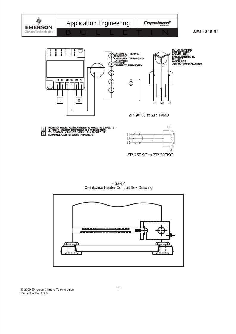
Motor Protection Module: The motor protection sys-tem consists of an external electronic control moduleconnected to a chain of four thermistors embedded inthe motor winding with a fifth thermistor located at theinternal scroll discharge port. The module will trip andremain off for 30 minutes if either the motor or dischargetemperature exceeds a preset point. Note: Turningoff power to the module will reset it immediately. Themodule has a 30 minute time delay to allow the scrollsto cool down after the discharge temperature limit hasbeen reached. Restarting the compressor sooner willcause a destructive temperature build up in the scrolls.For this reason module power must never be switchedwith the control circuit voltage. Since the compressor is dependent upon the contactor to disconnect it frompower in case of a fault the contactor must be selectedin accordance with AE Bulletin 10-1244. The contac-tor must meet both the Emerson Rated Load Amps(RLA) and Locked Rotor Amps (LRA) specified for thecompressor.
Protector Specification:Models 071-0520-04 071-0520-05Voltage 24 V 120/240 VControl Rating 60 VA 300/375 VA
25 A Inrush 25/15 A InrushNormal PTC resistance: 250 to 2250 OhmsTrip resistance: >4500 Ohm +/- 20%Reset resistance: <2750 OhmsModule time out: 30 minutes +/- 5 minutesLow Voltage Sensing: NonePhase Monitor: No
See “Solid State Module Field Trouble Shooting” at theend of this bulletin. It may take as long as two hoursfor the motor to cool down before the protector willreset. If current monitoring to the compressor is avail-able, the system controller can take advantage of thecompressor protector operation. The controller can bedesigned to lock out the compressor if current draw isnot coincident with a signal for the unit to run, implyingthat the compressor has shut off on its protector. Thiswill prevent unnecessary compressor cycling on a faultcondition until corrective action can be taken. The samelogic can be applied using voltage monitoring across thecontacts M1 and M2 of the protector module as well as
those of other safety devices to detect a trip in place of current monitoring if this is more convenient.
Accumulators
Due to the Copeland Scroll compressor’s inherent abilityto handle liquid refrigerant in flooded start and defrostcycle operation, an accumulator may not be requiredfor durability in most systems, especially those systemsdesigned with thermostatic expansion valves. However,large volumes of liquid refrigerant which repeatedlyflood back to the compressor during normal off cyclesor excessive liquid refrigerant floodback during defrostor varying loads, no matter what the system charge is,can dilute the oil. As a result, bearings are inadequatelylubricated and wear may occur.
To test for these conditions see the section entitled
EXCESSIVE LIQUID FLOODBACK TESTS at the endof this bulletin. If an accumulator must be used, an oilreturn orifice size in the range of 0.070 - 0.090 inches(1.8 – 2.3 mm) is recommended. A large-area protectivescreen no finer than 30 x 30 mesh (0.6 mm openings) isrequired to protect this small orifice from plugging withsystem debris. Tests have shown that a small screenwith a fine mesh can easily become plugged causing oilstarvation to the compressor bearings. Accumulatorsare a standard item in air to air heat pumps and areused even when a thermostatic expansion valve is usedto meter refrigerant in the heating mode. During lowambient conditions, the oil returning from the outdoor coil will be very viscous and difficult to return through the
accumulator if the expansion valve is working properly bymaintaining superheat. To prevent slow oil return it maybe possible to remove the accumulator from systemsthat use expansion valves in heating. To determine if theaccumulator can be removed, a defrost test must be runat an outdoor ambient of around 30°F (-1° C) in a highhumidity environment. This is to ensure that excessiveliquid does not flood back to the compressor duringreversing valve operation, especially when coming outof defrost. Excessive flood back occurs when the sumptemperature drops below the safe operation line shownin Figure 1 for more than 10 seconds.
Screens
The use of screens finer than 30 x 30 mesh (0.6 mmopenings) anywhere in the system is not recommended.Field experience has shown that finer mesh screensused to protect thermal expansion valves, capillarytubes, or accumulators can become temporarily or per-manently plugged with normal system debris and blockthe flow of either oil or refrigerant to the compressor.Such blockage can result in compressor failure.
7/28/2019 AE1316
http://slidepdf.com/reader/full/ae1316 3/15
3
AE4-1316 R1
© 2009 Emerson Climate Technologies
Printed in the U.S.A.
Application Engineering
B U L L E T I N
Crankcase Heaters
Table 4 lists crankcase heaters required for these com-pressors when the system charge exceeds that shown in
Table 6. The crankcase heater must be mounted belowthe oil removal valve located on the bottom shell. Thecrankcase heater must remain energized duringcompressor off cycles. If the crankcase heaters re-quire a conduit, one possible solution is to use a conduitadapter box shown in Table 4 and Figure 4.
The initial start in the field is a very critical period for any compressor because all load bearing surfaces arenew and require a short break-in period to carry highloads under adverse conditions. The crankcase heater must be turned on a minimum of 12 hours prior tostarting the compressor. This will prevent oil dilutionand bearing stress on initial start up. If it is not feasible
to turn on the crankcase heater 12 hours in advance of starting the compressor, then use one of the techniqueslisted below to prevent possible flooded-start damageto the compressor: 1) Direct a 500 watt heat lamp or other safe heat source (do not use torch) at the lower shell of the compressor for approximately 30 minutesto boil off any liquid refrigerant prior to starting; or 2)Bump start the compressor by manually energizing thecompressor contactor for about one second. Wait fiveseconds and again manually energize compressor for one second. Repeat this cycle several times until theliquid in the shell has been boiled off and the compressor can be safely started and run continuously.
Pumpdown Cycle
Recycling pumpdown for control of refrigerant migrationmay be used instead of, or in conjunction with, acrankcase heater when the compressor is located sothat cold air blowing over the compressor makes thecrankcase heater ineffective. The compressor dischargecheck valve is designed for low leak back and will allowthe use of recycling pump down without the additionof an external check valve. The low pressure controlcut-in and cut-out settings have to be reviewed since arelatively large volume of gas will re-expand from thehigh side of the compressor into the low side on shutdown. A one time pump down at the end of a run cycle
is not recommended since refrigerant can still migrateinto the compressor after a long shut down. If a onetime pump down is used a crankcase heater must beinstalled.
Minimum Run Time
There is no set answer to how often scroll compressorscan be started and stopped in an hour, since it is highlydependent on system configuration. There is no minimumoff time, because the scrolls start unloaded, even if the
system has unbalanced pressures. The most criticalconsideration is the minimum run time required toreturn oil to the compressor after startup. This is easilydetermined since these compressors are equipped witha sight glass. The minimum on time becomes the timerequired for oil lost on compressor startup to return tothe compressor sump and restore a normal level in thesight glass. Cycling the compressor for a shorter timethan this, for instance to maintain very tight temperaturecontrol, can result in progressive loss of oil and damageto the compressor. See Application Engineering Bulletin17-1262 for more information on preventing compressor short cycling.
Reversing Valves
Since Copeland Scroll compressors have a very highvolumetric efficiency, their displacements are lower than
those of comparable capacity reciprocating compressors. As a result, Emerson recommends that the capacityrating on reversing valves be no more than 2 times thenominal capacity of the compressor with which it will beused. This will ensure proper operation of the reversingvalve under all operating conditions.
The reversing valve solenoid should be wired so that thevalve does not reverse when the system is shut off by theoperating thermostat in the heating or cooling mode. If thevalve is allowed to reverse at system shutoff, suction anddischarge pressures are reversed to the compressor. Thisresults in pressures equalizing through the compressor which can cause the compressor to slowly rotate until
the pressures equalize. This condition does not affectcompressor durability but can cause unexpected soundafter the compressor is turned off.
Low Ambient Cut-Out
Low ambient cut-outs are not required to limit heat pumpoperation. However, the discharge temperature must belimited to 275°F (135°C) or below. Otherwise, the internaldischarge sensor may trip the motor protection.
Oil Type and Oil Removal
In HCFC R-22 applications mineral oil is used in thecompressors. 3GS oil may be used if the addition of oil in the field is required. Polyol ester lubricants must
be used with HFC refrigerants (R134a, R407C, etc.).Compressors using polyol ester oil are identified with an“E” in the model number. An example is the ZR12ME-TWD. Copeland Ultra 22 CC should be used if additionalPOE oil is needed in the field. Mobil Arctic EAL22CCor ICI Emkarate RL32CF oil may be used to rechargethese compressors if Ultra 22 is not available.
When a compressor is exchanged in the field it ispossible that a major portion of the oil from the replaced
7/28/2019 AE1316
http://slidepdf.com/reader/full/ae1316 4/15
4© 2009 Emerson Climate Technologies
Printed in the U.S.A.
AE4-1316 R1
Application Engineering
B U L L E T I N
compressor may still be in the system. While this maynot affect the reliability of the replacement compressor,the extra oil will add to rotor drag and increase power usage. To remove this excess oil, an access valve hasbeen added to the lower shell of the compressor. Thecompressor should be run for 10 minutes, shut downand the access valve opened until oil is between ¼ to1/3 of the sight glass. This operation should be repeatedat least twice to make sure the proper oil level has beenachieved. In tandem applications where sight glassesare not available, a Schrader valve may be added to thelower portion of the common oil/gas and equalizationline. The compressor should then be run for 10 minutes,shut down and the access valve opened until no oilflows. This should be repeated twice to make sure thatthe proper oil level has been achieved.
Shutoff Sound
Since Copeland Scroll compressors are also excellentgas expanders, they may run backward for a brief period at shutoff as the internal pressures equalize.
A low mass, disc-type check valve in the dischargetube of the compressor prevents the compressor from running backward for more than a second. Thismomentary reversal of direction of the scrolls has noeffect on compressor durability and is entirely normal.Development testing should include a review of theshutoff sound for acceptability in a particular system.
Discharge Mufflers
Flow through Copeland Scroll compressors is semi-continuous with relatively low pulsation. Externalmufflers, where they are normally applied to pistoncompressors today, may not be required for CopelandScroll compressors. Because of variability betweensystems, however, individual system tests should beperformed to verify acceptability of sound performance.When no testing is performed, mufflers are recommendedin heat pumps. A hollow shell muffler will work quitewell. The muffler should be located a minimum of sixinches (15 cm) to a maximum of 18 inches (46 cm)from the compressor for most effective operation. Thefurther the muffler is placed from the compressor withinthese ranges, the more effective it may be. If adequate
attenuation is not achieved, use a muffler with a larger cross-sectional area to inlet-area ratio. The ratio shouldbe a minimum of 20:1 with a 30:1 ratio recommended.The muffler should be from four to six inches (10-15cm) long.
Air Conditioning System Suction Line Noiseand Vibration
Copeland Scroll compressors inherently have low soundand vibration characteristics. However, the sound and
vibration characteristics differ in some respects fromthose of reciprocating compressors. In rare instances,these could result in unexpected sound complaints.
One vibration characteristic of the scroll compressor may result in a low level “beat” frequency that may bedetected as noise coming along the suction line intothe building under some conditions. Elimination of the“beat” can be achieved by attenuating the contributingfrequency. The most important frequency to avoidis the power supply line frequency for three phasecompressors. See Table 3 for common combinationsof design configurations. The scroll compressor makesboth a rocking and torsional motion, and enough flexibilitymust be provided in the suction line to prevent vibrationtransmission into any lines attached to the unit. In a splitsystem the most important goal is to ensure minimalvibration in all directions at the service valve to avoid
transmitting vibrations to the structure to which the linesare fastened.
A second difference of the Copeland Scroll compressor isthat under some conditions the normal rotational startingmotion of the compressor can transmit an “impact” noisealong the suction line. This may be particularly pronouncedin three phase models due to their inherently higher starting torque. This phenomenon, like the one describedpreviously, also results from the lack of internal suspension,and can be easily avoided by using standard suction lineisolation techniques as described in Table 3.
The sound phenomena described above are not usually
associated with heat pump systems because of theisolation and attenuation provided by the reversing valveand tubing bends.
Electrical Connections
The orientation of the electrical connections on theCopeland Scroll compressors is shown in Figure 3 andis also shown on the wiring diagram inside the terminalbox cover. The screw terminals used on this compressor should be fastened with a torque of 21 to 23 in-lb (2.5to 2.6 Nm).
Deep Vacuum Operation
Copeland Scroll compressors (as with any refrigerantcompressor) should never be used to evacuate arefrigeration or air conditioning system. The scrollcompressor can be used to pump down refrigerantin a unit as long as the pressures remain within theoperating envelope shown in Figure 2. Low suctionpressures will result in overheating of the scrolls andpermanent damage to the compressor drive bearing.(See Application Engineering Bulletin 24-1105 for proper system evacuation procedures.)
7/28/2019 AE1316
http://slidepdf.com/reader/full/ae1316 5/15
5
AE4-1316 R1
© 2009 Emerson Climate Technologies
Printed in the U.S.A.
Application Engineering
B U L L E T I N
Nomenclature
The model numbers of the Copeland Scroll compressorsinclude the approximate nominal 60 HZ capacity at ARI
rating conditions. An example would be the ZR90K3-TWD, which has approximately 90,000 Btu/hr coolingcapacity at the ARI high temperature air conditioningrating point when operated on 60 Hz. The letter “K” in the5th place of the model number indicates that the number preceding it is to be multiplied by 1000, “M” by 10,000.Note that the same compressor will have approximately5/6 of this capacity or 75000 Btu/hr when operated on50 Hz current. Please refer to the file “Nomenclature”found in “Online Product Information” on the EmersonClimate Technologies web page for details pertaining toother information contained in the model number.
Shell Temperature
Certain types of system failures, such as condenser or evaporator fan blockage or loss of charge, may cause thetop shell and discharge line to briefly but repeatedly reachtemperatures above 350°F (177°C) as the compressor cycles on its internal protection devices. Care must betaken to ensure that wiring or other materials, whichcould be damaged by these temperatures, do not comein contact with these potentially hot areas.
Suction and Discharge Fittings
The compressors are available with stub tube or a combination Rotalock connection and flanged
connection. The stub tube version has copper platedsteel suction and discharge fittings. These fittings arefar more rugged than copper fittings used on other compressors. Due to the different thermal propertiesof steel and copper, brazing procedures may have tobe changed from those commonly used. See Figure 5for assembly line and field brazing procedures. Table5 contains torque values for those compressors withvalve connections.
Rotation Direction of Three Phase ScrollCompressors
Scroll compressors, like several other types of compressors, will only compress in one rotational
direction. Direction of rotation is not an issue with singlephase compressors since they will always start and run inthe proper direction. Three phase compressors will rotatein either direction depending upon phasing of the power.Since there is a 50-50 chance of connecting power insuch a way as to cause rotation in the reverse direction, it is important to include notices and instructions inappropriate locations on the equipment to ensureproper rotation direction when the system is installedand operated. Verification of proper rotation direction
is made by observing that suction pressure dropsand discharge pressure rises when the compressor isenergized. Reverse rotation of the scroll compressor alsoresults in substantially reduced current draw comparedto specification sheet values.
There is no negative impact on durability caused byoperating three phase Copeland Scroll compressors inthe reversed direction for a short period of time (under one hour) but oil may be lost. Oil loss can be preventedduring reverse rotation if the tubing is routed at leastsix inches (15 cm) above the compressor. After severalminutes of operation in reverse, the compressor’sprotection system will trip. If allowed to repeatedly restartand run in reverse without correcting the situation, thecompressor will be permanently damaged.
All three phase scroll compressors are identically
wired internally. Therefore, once the correct phasingis determined for a specific system or installation,connecting properly phased power leads to the identifiedcompressor terminals will insure proper rotationdirection.
Brief Power Interruptions
No time delay is required on three phase models toprevent reverse rotation due to power interruptions. Thetorque of the motor is strong enough to assure proper rotation under all starting circumstances.
Assembly Line Brazing Procedure
Figure 5 discusses the proper procedures for brazingthe suction and discharge lines to a scroll compressor.It is important to flow nitrogen through the systemwhile brazing all joints during the system assemblyprocess. Nitrogen displaces the air and prevents theformation of copper oxides in the system. If allowedto form, the copper oxide flakes can later be sweptthrough the system and block screens such as thoseprotecting capillary tubes, thermal expansion valves, andaccumulator oil return holes. The blockage – whether it be of oil or refrigerant – is capable of doing damageresulting in compressor failure.
Assembly Line System Charging Procedure
Because scrolls have discharge check valves, systemsshould be charged on both the high and low sidesimultaneously to assure refrigerant pressure is presentin the compressor before it is Hi-Pot tested or operated.The majority of the charge should be placed in thehigh side of the system to prevent Hi-Pot failures andbearing washout during first-time start on the assemblyline. It is best to charge only vapor into the low side of the system.

7/28/2019 AE1316
http://slidepdf.com/reader/full/ae1316 6/15
6© 2009 Emerson Climate Technologies
Printed in the U.S.A.
AE4-1316 R1
Application Engineering
B U L L E T I N
Do not operate compressor without enough systemcharge to maintain at least 7 psig (0.5 kg/cm2)suction pressure. Do not operate with a restrictedsuction. Do not operate with the low pressure cut-
out jumpered.
Allowing pressure to drop below 7 psig (0.5 kg/cm2) for more than a few seconds may overheat scrolls and causeearly drive bearing damage.Do not use compressor totest opening setpoint of high pressure cutout. Bearingsare susceptible to damage before they have had severalhours of normal running for proper break in.
“Hipot” (AC High Potential) Testing
Copeland Scroll compressors are configured with themotor down and the pumping components at the topof the shell. As a result, the motor can be immersed in
refrigerant to a greater extent than hermetic reciprocatingcompressors when liquid refrigerant is present in theshell. In this respect, the scroll is more like semi-hermeticcompressors which can have horizontal motors partiallysubmerged in oil and refrigerant. When Copeland Scrollcompressors are Hipot tested with liquid refrigerantin the shell, they can show higher levels of leakagecurrent than compressors with the motor on top. Thisphenomenon can occur with any compressor when themotor is immersed in refrigerant. The level of currentleakage does not present any safety issue. If uncertaintyexists as to the source of the current leakage, testthe system with a resistance meter. If the resistancereading does not show a direct short to ground, lower
the current leakage reading by operating the systemfor a brief period of time to redistribute the refrigerantto a more normal configuration and Hi-Pot the systemagain. See AE Bulletin 4-1294 for Megohm testingrecommendations. Under no circumstances should theHipot test be performed while the compressor is under avacuum. The solid state module and sensors are delicateelectronic components and can easily be damaged byhigh voltage. Under no circumstances should a highpotential test be made of the sensors with the sensor leads attached to the module. If the sensors need to behigh potential tested, remove the leads from the moduleand short them together. Apply a maximum of 600 voltsto the sensor leads during this test.
Unbrazing System Components
Caution! Before opening a system it is importantto remove all refrigerant from both the high andlow side. If the refrigerant charge is removed from ascroll-equipped unit by bleeding the high side only, itis possible for the scrolls to seal, preventing pressureequalization through the compressor. This may leavethe low side shell and suction line tubing pressurized. If a brazing torch is then applied to the low side while the
low side shell and suction line contains pressure, thepressurized refrigerant and oil mixture could ignite whenit escapes and contacts the brazing flame. To preventthis occurrence, it is important to check both the high
and low side with manifold gauges before unbrazing.Instructions should be provided in appropriate productliterature and assembly (line repair) areas. If compressor removal is required, the compressor should be cut outof system rather than unbrazed. See Figure 5 for proper compressor removal procedure.
Copeland Scroll Compressor Functional Check
A functional compressor test with the suction servicevalve closed to check how low the compressor will pullsuction pressure is not a good indication of how well acompressor is performing. Such a test will damage ascroll compressor.The following diagnostic procedure
should be used to evaluate whether a Copeland Scrollcompressor is working properly.
Proper voltage to the unit should be verified.1.
The normal checks of motor winding continuity and2.short to ground should be made to determine if aninternal motor short or ground fault has developed.If the protector has opened, the compressor mustbe allowed to cool sufficiently to allow it to reset.
Proper indoor and outdoor blower/fan operation3.should be verified.
With service gauges connected to suction and4.
discharge pressure fittings, turn on the compressor.If suction pressure falls below normal levels, thesystem is either low on charge or there is a flowblockage in the system.
If suction pressure does not drop and discharge5.pressure does not rise to normal levels, reverseany two of the compressor power leads and reapplypower to make sure compressor was not wired torun in reverse direction. If pressures still do not moveto normal values, either the reversing valve (if soequipped) or the compressor is faulty. Reconnectthe compressor leads as originally configuredand use normal diagnostic procedures to check
operation of the reversing valve.
To test if the compressor is pumping properly,6.the compressor current draw must be comparedto published compressor performance curvesusing the operating pressures and voltage of thesystem. If the average measured current deviatesmore than ±15% from published values, a faultycompressor may be indicated. A current imbalanceexceeding 15% of the average on the three phases
7/28/2019 AE1316
http://slidepdf.com/reader/full/ae1316 7/15
7
AE4-1316 R1
© 2009 Emerson Climate Technologies
Printed in the U.S.A.
Application Engineering
B U L L E T I N
may indicate a voltage imbalance and should beinvestigated further. A more comprehensive trouble-shooting sequence for compressors and systemscan be found in Section H of the Emerson Climate
Technologies Electrical Handbook.
Before replacing or returning a compressor:7. Becertain that the compressor is actually defective.
As a minimum, recheck a compressor returnedfrom the field in the shop or depot for Hipot,winding resistance, and ability to start beforereturning. More than one-third of compressorsreturned to Emerson for warranty analysis aredetermined to have nothing found wrong. Theywere mis-diagnosed in the field as being defective.Replacing working compressors unnecessarilycosts everyone.
Tandem OperationThe 7.5 to 25 HP models are designed so that thecompressors may be piped together for parallel tandemoperation offering two steps of modulation. Either one or both compressors can run, depending upon the capacityrequirement. A discharge and suction manifold provide asingle point discharge and suction line connection. An oilequalization tube is installed between the compressorsto ensure that oil is distributed equally. The compressorsare mounted directly on two steel rails. This rigidmounting keeps the interconnecting tubing stresses toa minimum. The tandem assembly should be mountedon rubber isolating grommets to the unit basepan. Bothcompressors must be at the same level to prevent oilfrom migrating to the lowest compressor through theoil equalization line.
Handling: See handling instruction label on tandem.The tandem must be lifted so that the lifting chains gostraight up from the hanger tabs. If the tandem is hoistedfrom a single point so that the chain makes a “V “ themounting rails will bend and possibly collapse.
The individual compressors that make up the tandemare wired independently using the electrical valuesof the single compressors. It is recommended thatcompressors be wired to change lead/lag position. Thiswill ensure equal run time for both compressors, thereby
increasing reliability.
Table 4 lists crankcase heaters that must be mounted oneach compressor when the system charge exceeds thatshown in Table 6 by 20%.The crankcase heater mustbe located below the oil removal spud. See previoussection on Crankcase Heaters.
Pumpdown may be used instead of or in conjunctionwith crankcase heaters. See previous section onPumpdown.
Compressor Replacement
In the case of a motor burn, the majority of contaminatedoil will be removed with the compressor. The rest of the
oil is cleaned through use of suction and liquid line filter dryers. A 100% activated alumina suction filter drier isrecommended but must be removed after 72 hours.See AE Bulletin 24-1105 for clean up proceduresand AE Bulletin 11-1297 for liquid line filter-drier recommendations. It is highly recommended thatthe suction accumulator be replaced if the systemcontains one. This is because the accumulator oilreturn orifice or screen may be plugged with debris or may become plugged shortly after a compressor failure.This will result in starvation of oil to the replacementcompressor and a second failure.
When a single compressor or tandem is exchanged
in the field it is possible that a major portion of the oilmay still be in the system. While this may not affect thereliability of the replacement compressor, the extra oilwill add to rotor drag and increase power usage. Seeprevious section on Oil Type and Oil Removal.
SeeTable 5 for Rotalock valve, flange fitting, sight glass,and mounting bolt torque values.
Start-up of a New or Replacement Compressor
It is good service practice, when charging a system,to charge liquid refrigerant into the high side only andcharge the low side of the system with vapor only. It is
not good for any compressor to have liquid refrigerantdumped from a refrigerant cylinder into the crankcase of the compressor.Do not start the compressor while thesystem is in a deep vacuum. Internal arcing may occur when a scroll compressor is started in a vacuum.
Do not operate compressor without enough systemcharge to maintain at least 7 psig (0.5 kg/cm2)suction pressure. Do not operate with a restrictedsuction. Do not operate with the low pressure cut-out jumpered.
A minimum suction pressure of 25 psig (1.75 kg/cm2)must be maintained during charging. Allowing pres-
sure to drop below 7 psig (0.5 kg/cm2) for more thana few seconds may overheat scrolls and cause earlydrive bearing damage. Never install a system in thefield and leave it unattended when it has no charge, aholding charge, or with the service valves closed with-out securely locking out the system. This will preventunauthorized personnel from accidentally operatingthe system and potentially ruining the compressor byoperating with no refrigerant flow.
7/28/2019 AE1316
http://slidepdf.com/reader/full/ae1316 8/15
8© 2009 Emerson Climate Technologies
Printed in the U.S.A.
AE4-1316 R1
Application Engineering
B U L L E T I N
Excessive Liquid Floodback Tests
The following tests are for those system configurationsand charge levels identified in Table 1 that need
special testing to verify exemption from need of anaccumulator. Figure 1 applies only during floodback,not when the suction gas is superheated, and must beused to determine the effectiveness of an accumulator.The compressor sump temperature during any unit testwhere flood back occurs must remain within the “safezone” shown in Figure 1.
To test for excessive continuous liquid refrigerantflood back, it is necessary to operate the system in atest room at conditions where steady state floodback mayoccur (low ambient heating operation). Thermocouplesshould be attached with glue or solder to the center of the bottom shell and to the suction and discharge lines
approximately 6 inches (15 cm from the shell). Thesethermocouples should be insulated from the ambient air with Permagum® or other thermal insulation to be ableto record true shell and line temperatures. If the systemis designed to be field charged, it should be overchargedby 15% in this test to simulate overcharging commonlyfound in field installations.
The system should be operated at an indoor temperatureof 70°F (21°C) and outdoor temperature extremes(0°F or -18°C or lower in heating) to produce floodbackconditions. The compressor suction and dischargepressures and temperatures as well as the sumptemperature should be recorded. The system should be
allowed to frost up for several hours (disabling the defrostcontrol and spraying water on the outdoor coil may benecessary) to cause the saturated suction temperatureto fall to below -10°F (-23°C). The compressor sumptemperature must remain above the sump temperatureshown in Figure 1 or design changes must be made toreduce the amount of floodback. If an accumulator isused, an oil return orifice size of 0.070 - 0.090 inches(1.8 – 2.3 mm) is recommended. (See information on
Accumulators in Application Considerations and alsoAE Bulletin 11-1247). Increasing indoor coil volume,increasing outdoor air flow, reducing refrigerant charge,decreasing capillary or orifice diameter, and addinga charge compensator can also be used to reduce
excessive continuous liquid refrigerant floodback.
To test for repeated excessive liquid floodback duringnormal system off-cycles, perform the “Field ApplicationTest’’. Obtain a sample compressor with a side sighttube to measure liquid level in the compressor. Set thesystem up in a configuration with the indoor unit elevatedseveral feet above the outdoor unit with 25 feet (8 m)of connecting tubing and no traps between the indoor and outdoor units. If the system is designed to be fieldcharged, the system should be overcharged by 15% in
this test to simulate overcharging commonly found in fieldinstallations. Operate the system in the cooling mode atthe outdoor ambients, on/off cycle times, and number of cycles specified in Table 1. Record the height of the
liquid in the compressor at the start of each on cycle, anyprotector trips, or any compressor stalls during each test.Review the results with Emerson Climate Technologies
Application Engineering to determine if an accumulator is required for the application. The criteria for pass/fail iswhether the liquid level is above the compressor suctionconnection. Liquid levels higher than these allow anycompressor oil floating on top of the refrigerant to beingested by the scrolls and pumped out of the compressor on startup, a hazardous situation.
Field Trouble Shooting Solid State ModulePart Number 071-0520-XX
The module used in the 7.5 to 25 HP scroll compressor works in conjunction with a thermistor chain inside thescroll compressor to protect against excessive motor anddischarge gas temperature. A problem in either area willcause the module to interrupt the control circuit (openM1 & M2) for 30 minutes +/- 5 minutes. Follow the stepslisted below to trouble shoot the module in the field. Seewiring diagram below or on terminal box cover.
De-energize control circuit and module power.1.Remove the control circuit wires from themodule (Terminals M1 & M2). Connect a jumper across these “control circuit” wires. This willbypass the “control contact” of the module.
CAUTION: THE MOTOR PROTECTION SYSTEMWITHIN THE COMPRESSOR IS NOW BYPASSED.USE THIS CONFIGURATION TO TEMPORARILYTEST MODULE ONLY !
Re-energize the control circuit and module power.2.
If the compressor will not operate withthe jumper installed, then the problem isexternal to the solid state protection system.
If the compressor operates with the modulebypassed but will not operate when the module is
reconnected, then the control circuit relay in themodule is open. The thermistor protection chainnow needs to be tested to determine if the module’scontrol circuit relay is open due to excessive internaltemperatures or a faulty component.
Check the thermistor protect ion chain3.located in the compressor as fol lows:
De-energize control circuit and module power.Remove the sensor leads from the module (S1 & S2).

7/28/2019 AE1316
http://slidepdf.com/reader/full/ae1316 9/15
9
AE4-1316 R1
© 2009 Emerson Climate Technologies
Printed in the U.S.A.
Application Engineering
B U L L E T I N
Measure the resistance of the thermistor protectionchain through these sensor leads with an ohmmeter.
CAUTION ! Use an Ohmmeter with a maximumof 9 volts to check the sensor chain. The sensor chain is sensitive and easily damaged; no attemptshould be made to check continuity through it withanything other than an ohmmeter. The applicationof any external voltage to the sensor chain maycause damage requiring the replacement of thecompressor.
The diagnosis of this resistance reading is asfollows:
250 to 2250 ohms – Normal operating range•
2750 ohms or greater – Compressor overheated•
- Allow time to cool
zero resistance – Shorted sensor circuit –•Replace the compressor
infinite resistance – Open sensor circuit –•Replace the compressor
If the resistance reading is abnormal, remove thesensor connector plug from the compressor andmeasure the resistance at the sensor fusite pins.This will determine if the abnormal reading was dueto a faulty connector or the thermistors.
On initial start-up, and after any module trip, the
resistance of the sensor chain must be below themodule reset point before the module circuit willclose. Reset values are 2250-3000 ohms.
If the sensor chain has a resistance that is4.below 2250 ohms, and the compressor will runwith the control circuit bypassed, but will notrun when connected properly, the solid statemodule is defective and should be replaced. Thereplacement module must have the same supplyvoltage rating as the original module.
Notes: The module has a 30-minute time out after a trip.Interrupting the module power for 1 second or longer
will reset the module.
The voltage should be disconnected between tests inorder to avoid short circuits and accidental arcing of contacts. The function of the module should be checkedeach time there is an open fuse or breaker trip to insurethat the module contacts did not stick.

7/28/2019 AE1316
http://slidepdf.com/reader/full/ae1316 10/15
10© 2009 Emerson Climate Technologies
Printed in the U.S.A.
AE4-1316 R1
Application Engineering
B U L L E T I N
0
10
20
30
40
50
60
70
80
90
100
-10 0 10 20 30 40 50
Evaporating Temp. (°F)
C o m p r e s s o r S u m p T e m p .
( ° F )
Evaporating Temp. (°C)
C om pr e s s or S um pT e m p . ( ° C )
Safe Area
Unsafe Area(Too much refrigerant dilution)
200°F (93.3 °C) Max. Oil Temp.
-20 -15 -10 -5 0 5 10
30
20
10
0
-10
Safe Area
Evaporating Temp. ( oF)
Full operating envelope is for ZR90K3E toZR19M3E and ZR250KCE and ZR300KCE with R407C atdewpoint. Dashed line indicates reduced operating envelope required for ZR90K3 to ZR19M3 andZR250KC to ZR300KC with R22.
Evaporating Temp.( oC)
C
o n d e n s i n g T e m p .
(
o F )
110
170
160
150
140
130
120
100
90
70
-20 -10 0 10 20 30 40 50 60
-25 -20 -15 -10 -5 0 5 10 15 20
70
60
50
40
3080
C on d en s i n gT em p . ( o C )
Figure 1Oil Dilution Chart
Figure 2R22 & R407C Scroll Operating Envelope
7/28/2019 AE1316
http://slidepdf.com/reader/full/ae1316 11/15
11
AE4-1316 R1
© 2009 Emerson Climate Technologies
Printed in the U.S.A.
Application Engineering
B U L L E T I N
Figure 4Crankcase Heater Conduit Box Drawing
ZR 90K3 to ZR 19M3
ZR 250KC to ZR 300KC
7/28/2019 AE1316
http://slidepdf.com/reader/full/ae1316 12/15
12© 2009 Emerson Climate Technologies
Printed in the U.S.A.
AE4-1316 R1
Application Engineering
B U L L E T I N
} } }
123
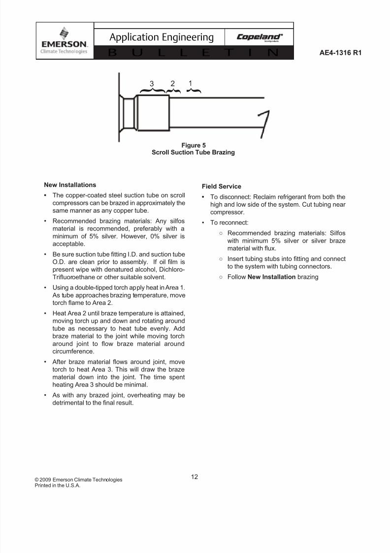
The copper-coated steel suction tube on scrollcompressors can be brazed in approximately the
same manner as any copper tube.
6 Recommended brazing materials: Any silfos
material is recommended, preferably with a
minimum of 5% silver. However, 0% silver is
acceptable.
6 Be sure suction tube fitting I.D. and suction tube
O.D. are clean prior to assembly. If oil film is
present wipe with denatured alcohol, Dichloro-
Trifluoroethane or other suitable solvent.
6
Using a double-tipped torch apply heat in Area 1. As tube approaches brazing temperature, move
torch flame to Area 2.
6 Heat Area 2 until braze temperature is attained,
moving torch up and down and rotating around
tube as necessary to heat tube evenly. Add
braze material to the joint while moving torch
around joint to flow braze material around
circumference.
6 After braze material flows around joint, move
torch to heat Area 3. This will draw the braze
material down into the joint. The time spent
heating Area 3 should be minimal.6 As with any brazed joint, overheating may be
detrimental to the final result.
To disconnect: Reclaim refrigerant from both the
high and low side of the system. Cut tubing near
compressor.
6 To reconnect:
Recommended brazing materials: Silfos
with minimum 5% silver or silver braze
material with flux.
Insert tubing stubs into fitting and connect
to the system with tubing connectors.
Follow brazing

7/28/2019 AE1316
http://slidepdf.com/reader/full/ae1316 13/15
13
AE4-1316 R1
© 2009 Emerson Climate Technologies
Printed in the U.S.A.
Application Engineering
B U L L E T I N
N o n - B l e e d
T X V
N o n - B l e e d
T X V
O t h e r ( 1 )
O t h e r
( 1 )
N o t
R e q u i r e d
N o t
R e q u i r e d
O t h e r ( 1 )
R e q u i r e d
R e q u i r e d
N o t
R e q u
i r e d
N o t
R e q u i r e d
R e q u i r e d
N o t
R e q u i r
e d
R e q u i r e d
R e q u i r e d
N o t
R e q u i r e d
R e q u i r e d
R e q u i r e d
R e q u i r e d
O t h e r ( 1 )
N o m i n a l
S y s t e m
C h a r g e
( 2 ) ( 1
) “ O t h e r " i n c l u d
e s b l e e d - t y p e T X V s , c a p i l l a r y t u b e
s , a n d fi x e d o r i fi c e s
( 2 ) “ N o m i n a l S y s
t e m C
h a r g e ” i s d e fi n e d a s t h e d e s
i g n c h a r g e f o r a s y s t e m
N o t e : S e e
t e x t f o r c r a n k c a s e h e a t e r r e q u i r e m
e n t s .
* 1 2 0 % T i
m e s C o m p r e s s o r r e f r i g e r a n t c h a r g e
l i m i t i n T a b l e 6 .
Scroll Compressor Application Diagram
7/28/2019 AE1316
http://slidepdf.com/reader/full/ae1316 14/15
14© 2009 Emerson Climate Technologies
Printed in the U.S.A.
AE4-1316 R1
Application Engineering
B U L L E T I N
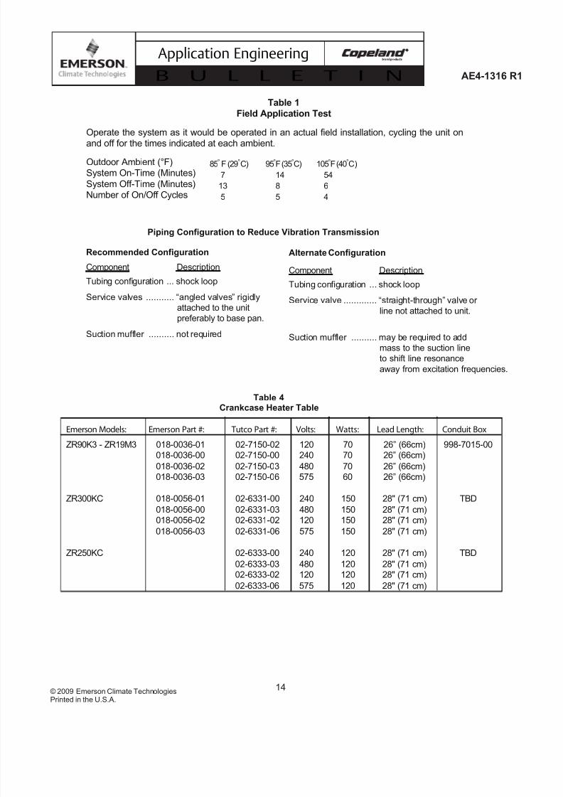
Recommended Configuration
Component Description
Tubing configuration ... shock loop
Service valves ........... “angled valves” rigidly
attached to the unit
preferably to base pan.
Suction muffler .......... not required
Alternate Configuration
Component Description
Tubing configuration ... shock loop
Service valve ............. “straight-through” valve or
line not attached to unit.
Suction muffler .......... may be required to add
mass to the suction line
to shift line resonance
away from excitation frequencies.
Piping Configuration to Reduce Vibration Transmission
Table 4Crankcase Heater Table
Emerson Models: Emerson Part #: Tutco Part #: Volts: Watts: Lead Length: Conduit Box
ZR90K3 - ZR19M3 018-0036-01 02-7150-02 120 70 26” (66cm) 998-7015-00
018-0036-00 02-7150-00 240 70 26” (66cm)
018-0036-02 02-7150-03 480 70 26” (66cm)
018-0036-03 02-7150-06 575 60 26” (66cm)
ZR300KC 018-0056-01 02-6331-00 240 150 28" (71 cm) TBD
018-0056-00 02-6331-03 480 150 28" (71 cm)
018-0056-02 02-6331-02 120 150 28" (71 cm)
018-0056-03 02-6331-06 575 150 28" (71 cm)
ZR250KC 02-6333-00 240 120 28" (71 cm) TBD
02-6333-03 480 120 28" (71 cm)
02-6333-02 120 120 28" (71 cm)
02-6333-06 575 120 28" (71 cm)
Table 1Field Application Test
Operate the system as it would be operated in an actual field installation, cycling the unit onand off for the times indicated at each ambient.
Outdoor Ambient (°F) 85 95 105System On-Time (Minutes) 7 14 54
System Off-Time (Minutes) 13 8 6Number of On/Off Cycles 5 5 4
85° F (29° C) 95° F (35° C) 105° F (40° C)
7 14 54
13 8 6
5 5 4
7/28/2019 AE1316
http://slidepdf.com/reader/full/ae1316 15/15
15
AE4-1316 R1
© 2009 Emerson Climate Technologies
Application Engineering
B U L L E T I N
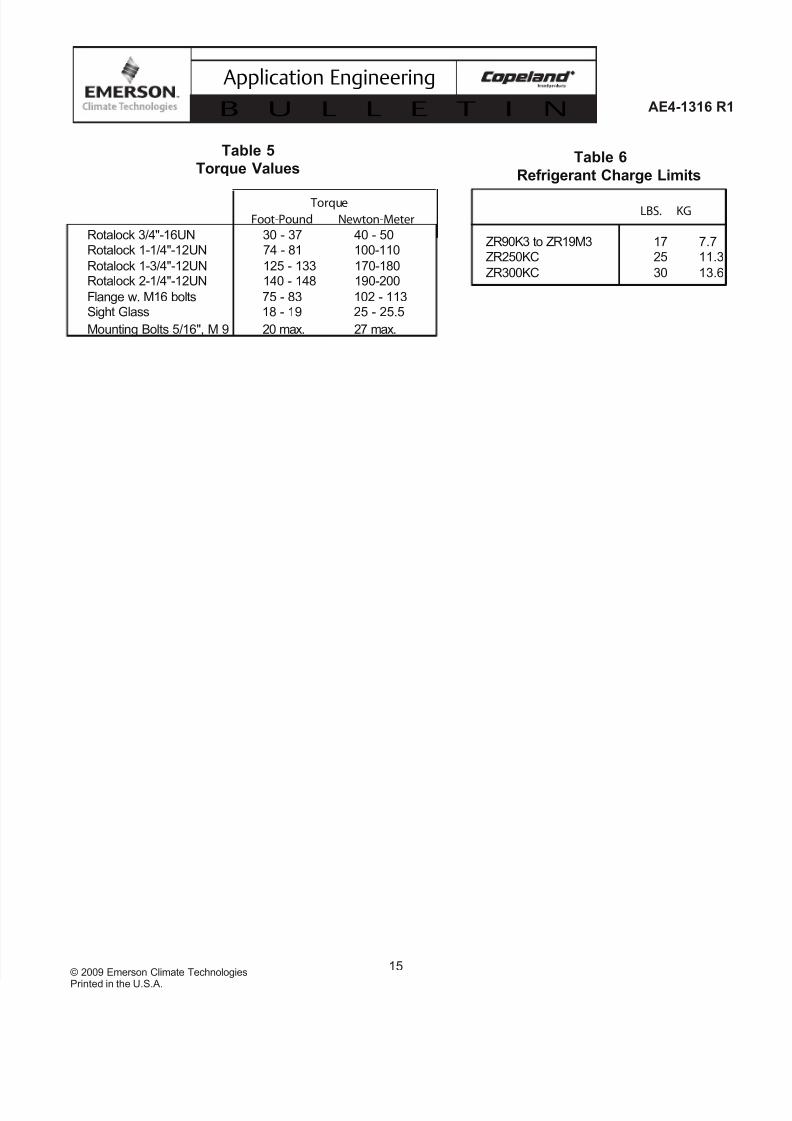
Table 5
Torque Values
Torque
Foot-Pound Newton-Meter
Rotalock 3/4"-16UN 30 - 37 40 - 50Rotalock 1-1/4"-12UN 74 - 81 100-110
Rotalock 1-3/4"-12UN 125 - 133 170-180Rotalock 2-1/4"-12UN 140 - 148 190-200
Flange w. M16 bolts 75 - 83 102 - 113Sight Glass 18 - 19 25 - 25.5
Mounting Bolts 5/16", M 9 20 max. 27 max.
Table 6
Refrigerant Charge Limits
LBS. KG
ZR90K3 to ZR19M3 17 7.7ZR250KC 25 11.3
ZR300KC 30 13.6


