Embed Size (px)
DESCRIPTION
Presentacion de Levantamiento Artificial
Citation preview
© 2006 Weatherford. All rights reserved.1
Artificial Lift Overview
© 2006 Weatherford. All rights reserved.2
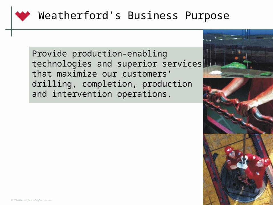
Weatherford’s Business Purpose
Provide production-enabling technologies and superior services that maximize our customers’ drilling, completion, production and intervention operations.
2
© 2006 Weatherford. All rights reserved.3
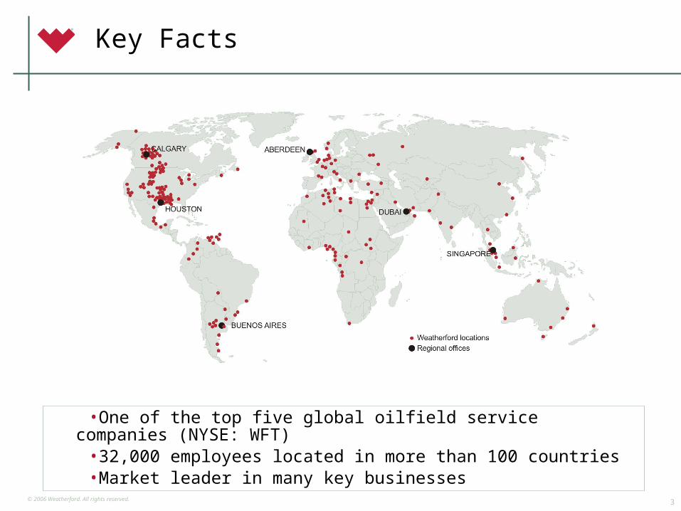
•One of the top five global oilfield service companies (NYSE: WFT)•32,000 employees located in more than 100 countries•Market leader in many key businesses
Key Facts
© 2006 Weatherford. All rights reserved.4
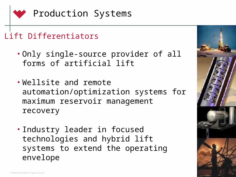
Lift Differentiators
Production Systems
• Only single-source provider of all forms of artificial lift
• Wellsite and remote automation/optimization systems for maximum reservoir management recovery
• Industry leader in focused technologies and hybrid lift systems to extend the operating envelope
4
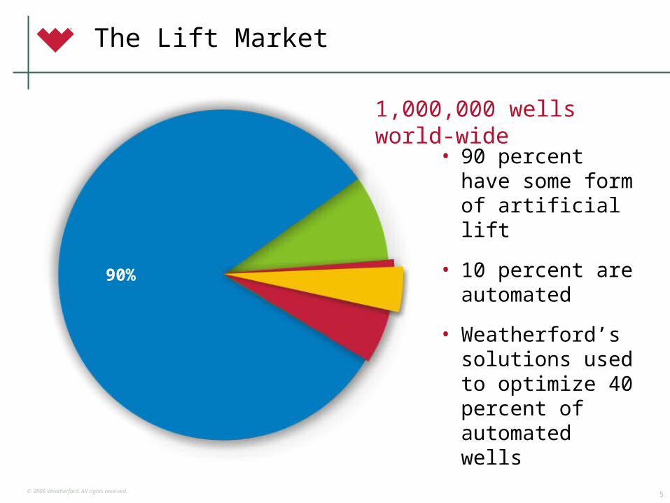
© 2006 Weatherford. All rights reserved.5
1,000,000 wells world-wide
The Lift Market
• 90 percent have some form of artificial lift
• 10 percent are automated
• Weatherford’s solutions used to optimize 40 percent of automated wells
90%
© 2006 Weatherford. All rights reserved.6
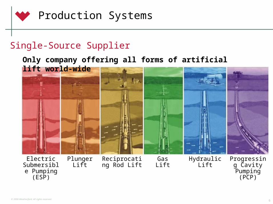
Production Systems
Electric Submersible
Pumping(ESP)
PlungerLift
Reciprocating Rod Lift
GasLift
HydraulicLift
Progressing Cavity
Pumping (PCP)
Only company offering all forms of artificial lift world-wide
Single-Source Supplier
© 2006 Weatherford. All rights reserved.7
Artificial Lift Secular Trends
• Maturing reservoirs and increasing decline rates
• Industry consolidation
• Technology mandate to optimize reservoir productivity
• Development of intelligent well systems
© 2006 Weatherford. All rights reserved.8
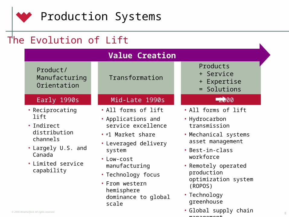
Production Systems
The Evolution of Lift
Product/ Manufacturing Orientation
Transformation
Products+ Service+ Expertise = Solutions
Early 1990s Mid-Late 1990s 2000
• Reciprocating lift
• Indirect distribution channels
• Largely U.S. and Canada
• Limited service capability
• All forms of lift
• Applications and service excellence
• #1 Market share
• Leveraged delivery system
• Low-cost manufacturing
• Technology focus
• From western hemisphere dominance to global scale
• All forms of lift
• Hydrocarbon transmission
• Mechanical systems asset management
• Best-in-class workforce
• Remotely operated production optimization system (ROPOS)
• Technology greenhouse
• Global supply chain management
• Exploit core competency beyond traditional markets
Value Creation
© 2006 Weatherford. All rights reserved.9
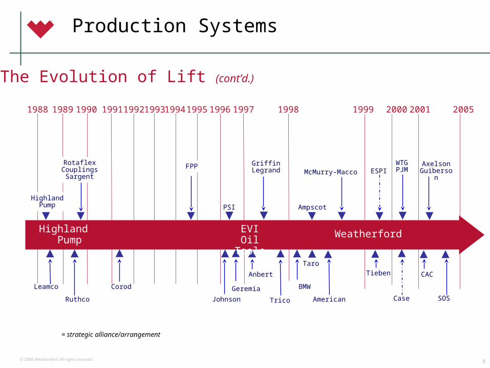
Production Systems
= strategic alliance/arrangement
The Evolution of Lift (cont’d.)
AmpscotHighland
Pump
Leamco
AxelsonGuiberson
1988 1990 1996199519941993199219911989 1997 1998
Corod
Ruthco
Geremia
Anbert
PSI
Griffin Legrand
Johnson Trico
BMW
Taro
American
1999
McMurry-Macco
Tieben
ESPI
2000
WTGPJM
Case
EVIOil Tools
WeatherfordHighland Pump
2001
CAC
RotaflexCouplingsSargent
FPP
2005
SOS
© 2006 Weatherford. All rights reserved.10
• Composite PC pump
• Constant thickness stator for PCP
• Constant volume rotating pump
• Downhole water Injection
• Hybrid lift technologies advancement
• Mixed phase Pumping
• Deepwater gas lift valves
New Technology Focus
Lift Technology Advances
© 2006 Weatherford. All rights reserved.11
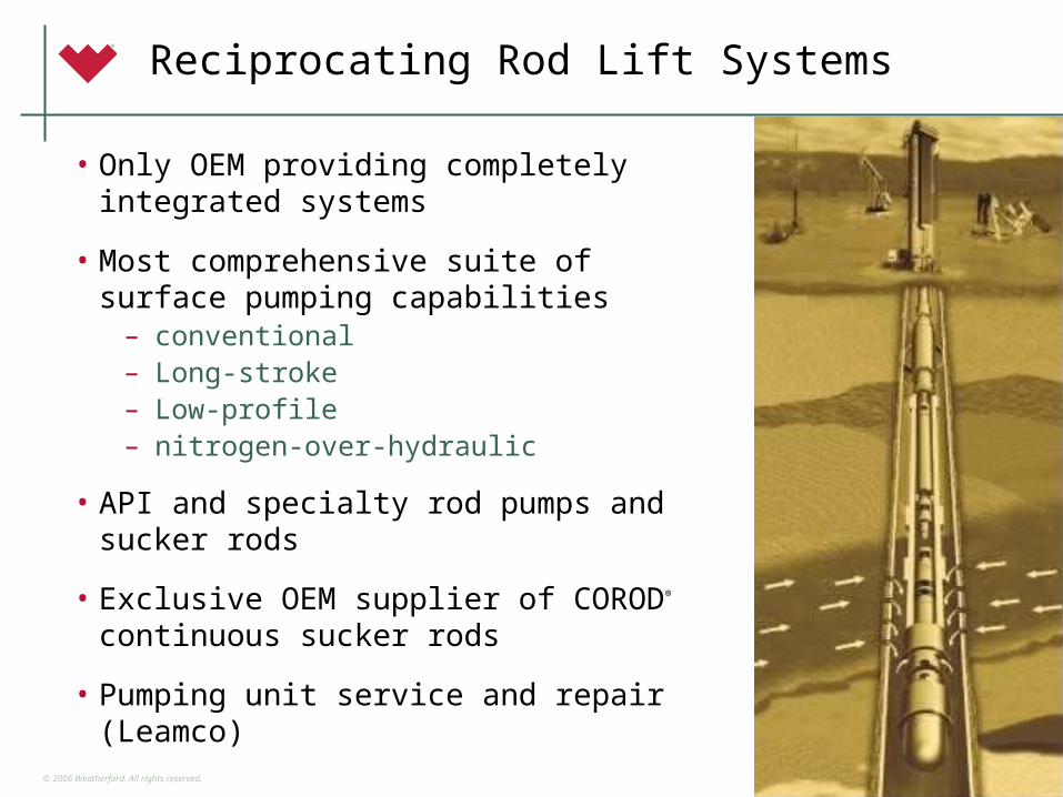
Reciprocating Rod Lift Systems
• Only OEM providing completely integrated systems
• Most comprehensive suite of surface pumping capabilities
– conventional – Long-stroke– Low-profile– nitrogen-over-hydraulic
• API and specialty rod pumps and sucker rods
• Exclusive OEM supplier of COROD® continuous sucker rods
• Pumping unit service and repair (Leamco)
© 2006 Weatherford. All rights reserved.12
ESPs
• Complete system offering, including complete downhole monitoring system
• Leading developer of ESP technology for coalbed methane applications
• Technology leader in expansion of ESPs into hybrid artificial lift systems
• Turnkey project capability, including full system optimization packages
• Ability to provide ALL downhole ESP completion equipment in-house, including SSDs, valves, packers, etc.
© 2006 Weatherford. All rights reserved.13
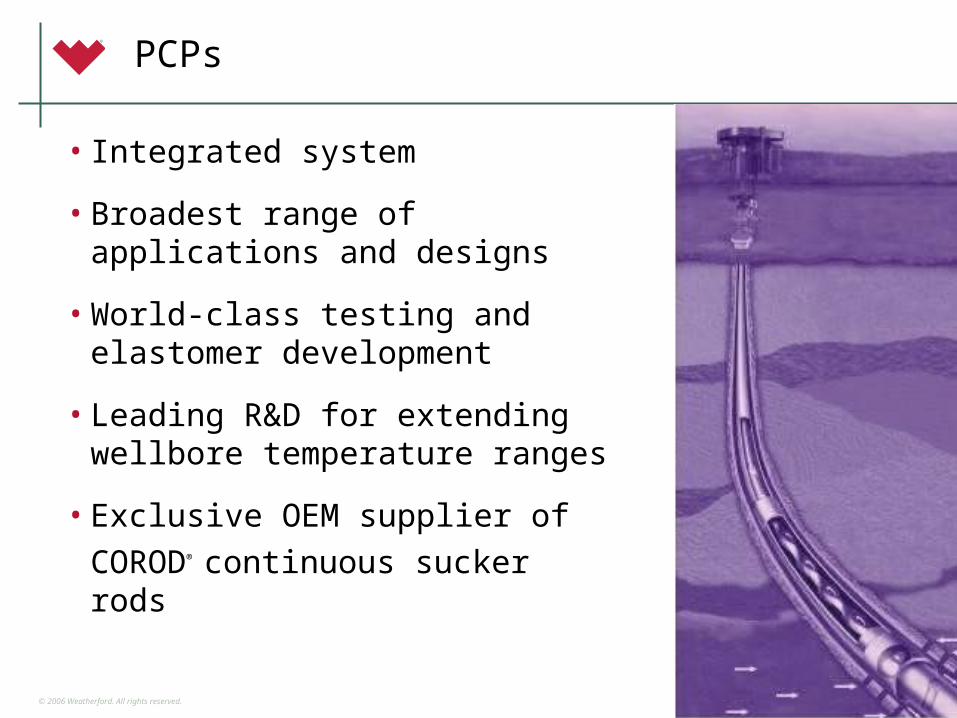
PCPs
• Integrated system
• Broadest range of applications and designs
• World-class testing and elastomer development
• Leading R&D for extending wellbore temperature ranges
• Exclusive OEM supplier of COROD®
continuous sucker rods

© 2006 Weatherford. All rights reserved.14
Gas Lift Systems
• Complete system integration
• Full range of downhole capabilities, including waterflood and chemical injection
• Leading developer of new valve technology
• Market leader in deepwater and extreme environment solutions
• High level of experience in application design and innovation
© 2006 Weatherford. All rights reserved.15
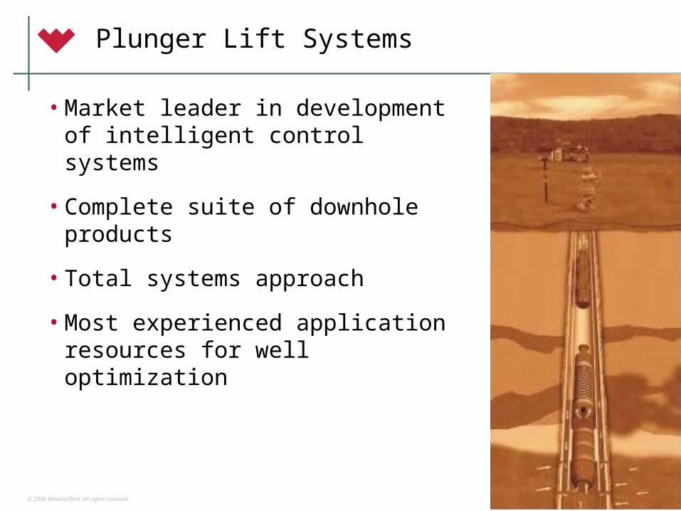
Plunger Lift Systems
• Market leader in development of intelligent control systems
• Complete suite of downhole products
• Total systems approach
• Most experienced application resources for well optimization
© 2006 Weatherford. All rights reserved.16
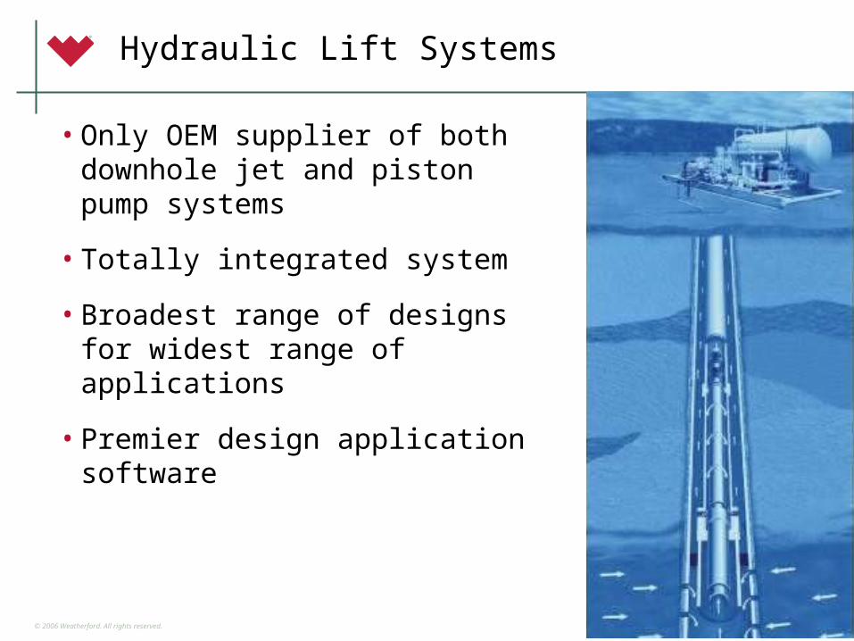
Hydraulic Lift Systems
• Only OEM supplier of both downhole jet and piston pump systems
• Totally integrated system
• Broadest range of designs for widest range of applications
• Premier design application software
© 2006 Weatherford. All rights reserved.17
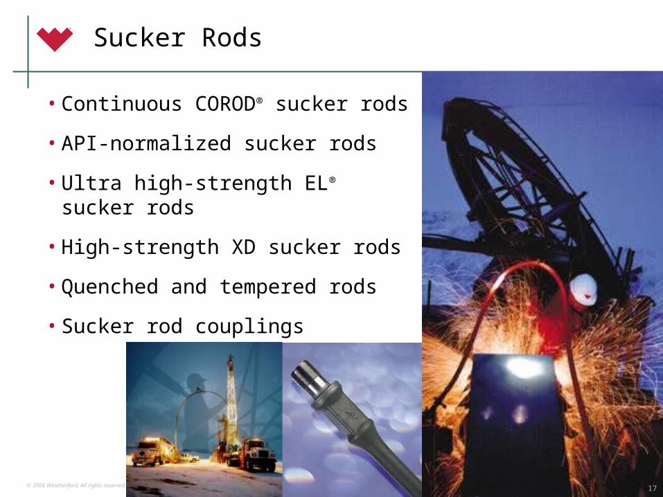
Sucker Rods
• Continuous COROD® sucker rods
• API-normalized sucker rods
• Ultra high-strength EL® sucker rods
• High-strength XD sucker rods
• Quenched and tempered rods
• Sucker rod couplings
17
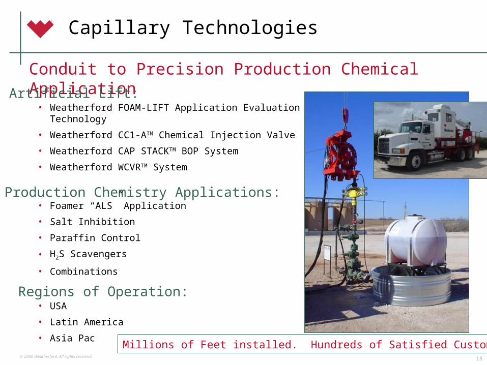
© 2006 Weatherford. All rights reserved.18
Capillary Technologies
Conduit to Precision Production Chemical Application
• Weatherford FOAM-LIFT Application Evaluation Technology
• Weatherford CC1-ATM Chemical Injection Valve
• Weatherford CAP STACKTM BOP System
• Weatherford WCVRTM System
Artificial Lift:
Production Chemistry Applications:• Foamer “ALS” Application
• Salt Inhibition
• Paraffin Control
• H2S Scavengers
• Combinations
Regions of Operation:• USA
• Latin America
• Asia PacMillions of Feet installed. Hundreds of Satisfied Customers!
© 2006 Weatherford. All rights reserved.19
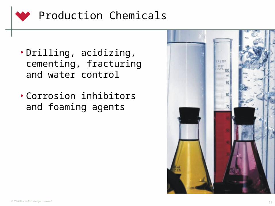
Production Chemicals
• Drilling, acidizing, cementing, fracturing and water control
• Corrosion inhibitors and foaming agents
© 2006 Weatherford. All rights reserved.20
Field Automation/ Optimization Systems
© 2006 Weatherford. All rights reserved.21
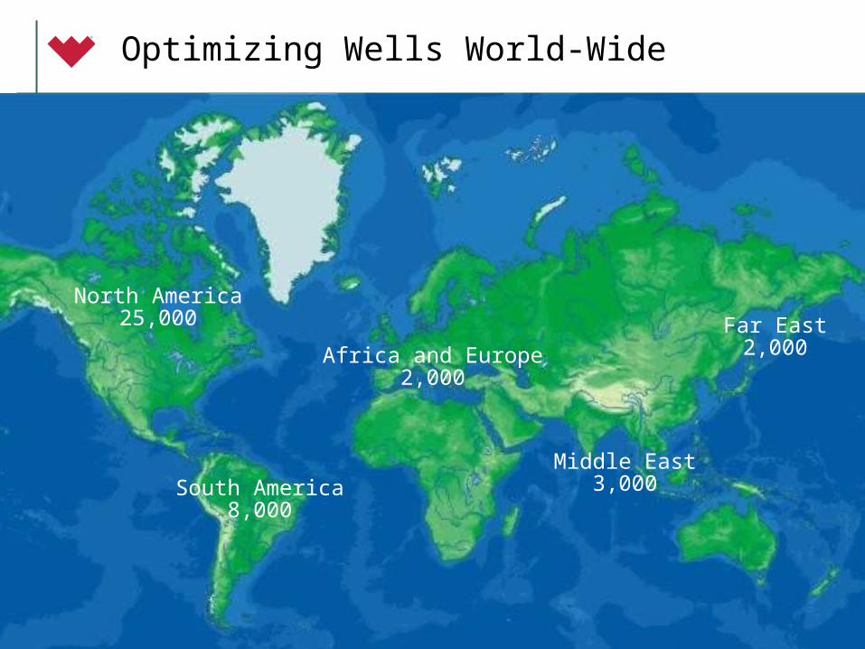
Optimizing Wells World-Wide
South America8,000
North America25,000
Middle East3,000
Far East2,000Africa and Europe
2,000

© 2006 Weatherford. All rights reserved.22
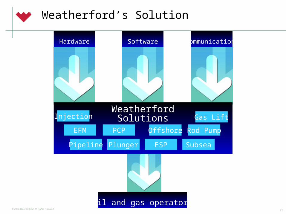
Traditional Production Optimization
Hardware
S Y S T E M I N T E G R A T O R
Software Communications
Communications
Oil and gas operators
© 2006 Weatherford. All rights reserved.23
Hardware Software Communications
WeatherfordSolutions Gas Lift
Rod Pump
Injection
EFM
SubseaPipeline Plunger ESP
OffshorePCP
Oil and gas operators
Weatherford’s Solution
© 2006 Weatherford. All rights reserved.24
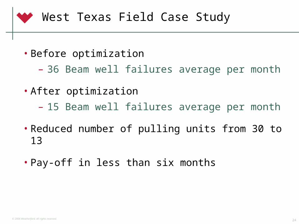
West Texas Field Case Study
• Before optimization
– 36 Beam well failures average per month
• After optimization
– 15 Beam well failures average per month
• Reduced number of pulling units from 30 to 13
• Pay-off in less than six months
© 2006 Weatherford. All rights reserved.25
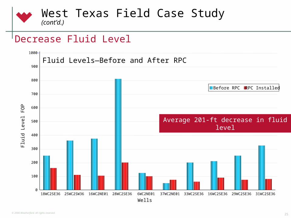
Flu
id L
eve
l FO
P
0
100
200
300
400
500
600
700
800
900
1000
18WC2SE36 25WC2SW36 16WC2NE01 28WC2SE36 6WC2NE01 37WC2NE01 33WC2SE36 16WC2SE36 29WC2SE36 31WC2SE36
Before RPC RPC Installed
Average 201-ft decrease in fluid level
Wells
West Texas Field Case Study (cont’d.)
Fluid Levels—Before and After RPC
Decrease Fluid Level

© 2006 Weatherford. All rights reserved.26
WEATHERFORD ALS
© 2006 Weatherford. All rights reserved.27
Breakthrough Technology
ClearWELL
Prevention of Scale and Paraffin Deposition
© 2006 Weatherford. All rights reserved.28
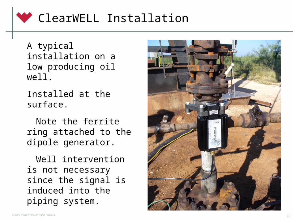
ClearWELL Installation
A typical installation on a low producing oil well.
Installed at the surface.
Note the ferrite ring attached to the dipole generator.
Well intervention is not necessary since the signal is induced into the piping system.
© 2006 Weatherford. All rights reserved.29
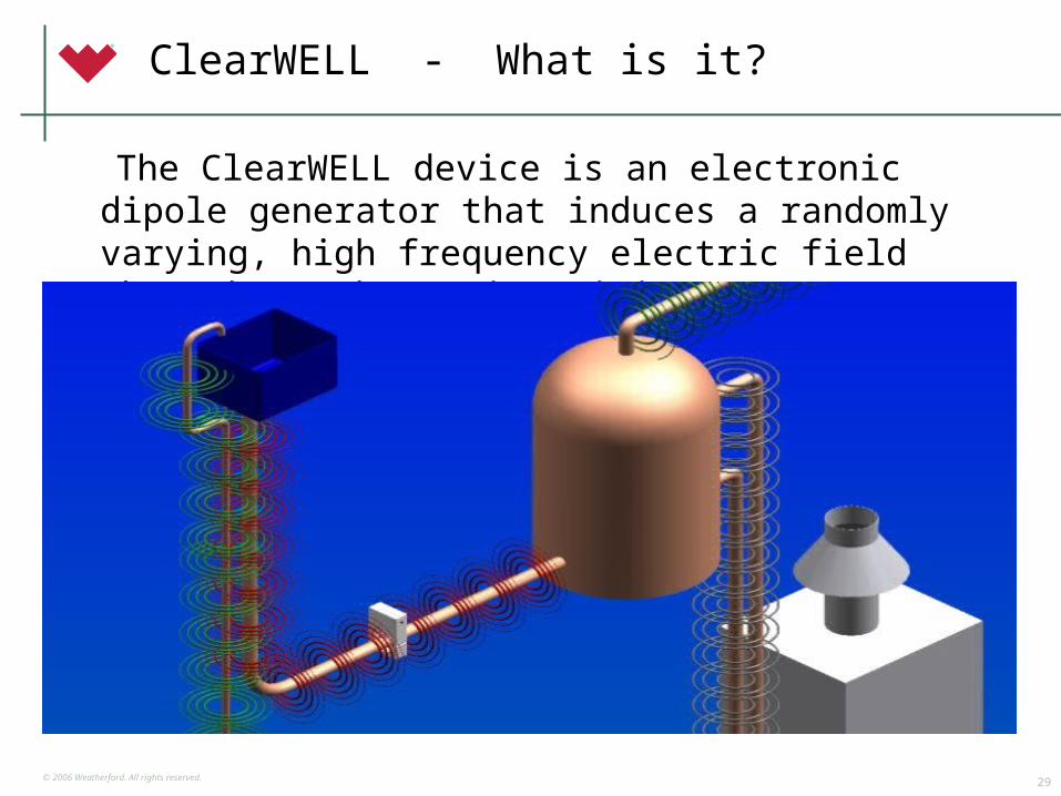
ClearWELL - What is it?
The ClearWELL device is an electronic dipole generator that induces a randomly varying, high frequency electric field throughout the entire piping system.
© 2006 Weatherford. All rights reserved.30
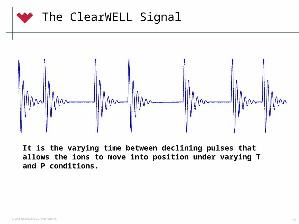
The ClearWELL Signal
It is the varying time between declining pulses that allows the ions to move into position under varying T and P conditions.
© 2006 Weatherford. All rights reserved.31
ClearWELL - How does it work?
• Reservoir fluids flowing into a well bore can reach a super saturation condition due to the pressure drop or change in temperature, thereby causing scale to precipitate on the piping and down hole equipment
• The electric field generated by the ClearWELL device forces homogeneous crystal formation in suspension rather than on metal surfaces
• Scale crystallizes in suspension and is carried away with the oil water mixture
• Residual carbonic acid will gradually dissolve any carbonate scale that had previously adhered to the walls of the piping system
• Any paraffin present in solution will adhere to the scale and be carried away as well
© 2006 Weatherford. All rights reserved.32
ClearWELL Results
© 2006 Weatherford. All rights reserved.33
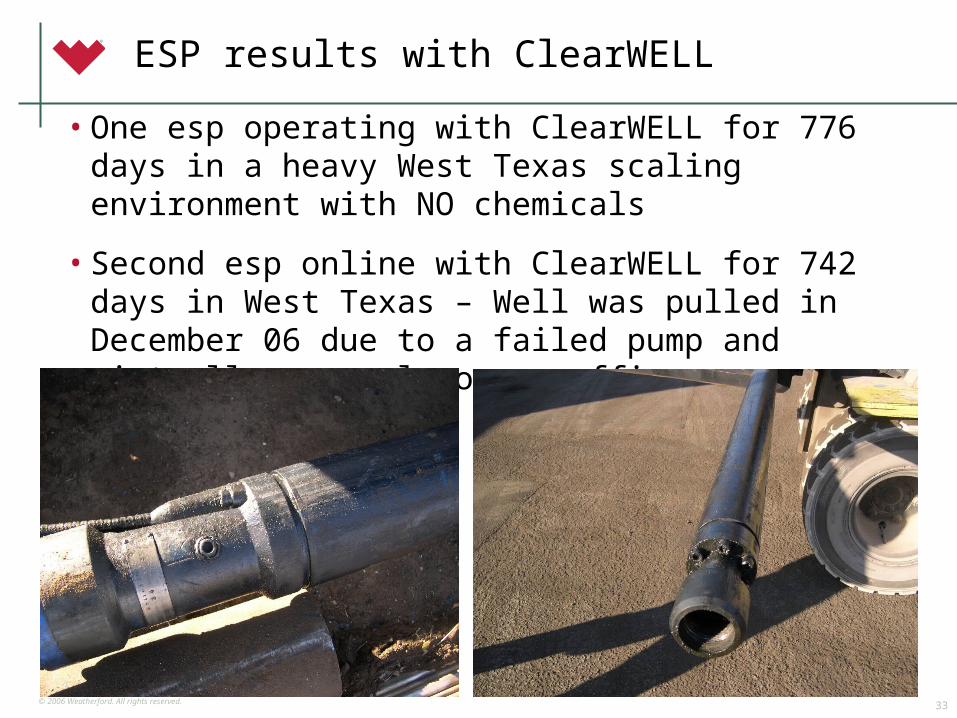
ESP results with ClearWELL
• One esp operating with ClearWELL for 776 days in a heavy West Texas scaling environment with NO chemicals
• Second esp online with ClearWELL for 742 days in West Texas – Well was pulled in December 06 due to a failed pump and virtually no scale or paraffin was seen – 2/1/08
© 2006 Weatherford. All rights reserved.34
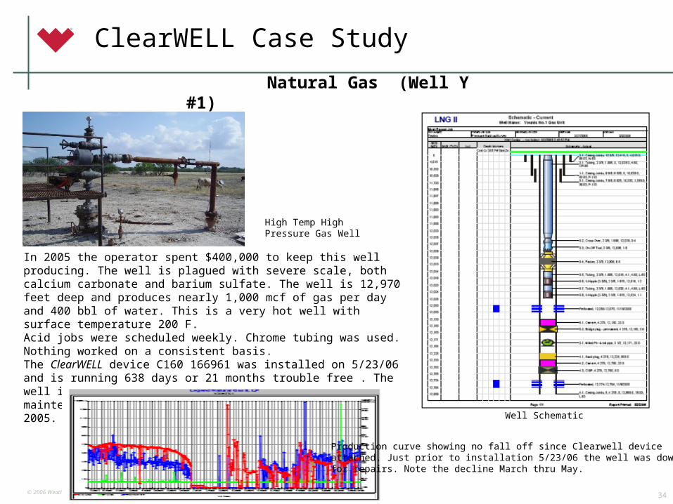
Natural Gas (Well Y #1)
In 2005 the operator spent $400,000 to keep this well producing. The well is plagued with severe scale, both calcium carbonate and barium sulfate. The well is 12,970 feet deep and produces nearly 1,000 mcf of gas per day and 400 bbl of water. This is a very hot well with surface temperature 200 F. Acid jobs were scheduled weekly. Chrome tubing was used. Nothing worked on a consistent basis.The ClearWELL device C160 166961 was installed on 5/23/06 and is running 638 days or 21 months trouble free . The well is not showing any scaling tendency and the maintenance savings have been substantial compared to 2005. March 1, 2008
Well Schematic
High Temp High Pressure Gas Well
Production curve showing no fall off since Clearwell deviceattached. Just prior to installation 5/23/06 the well was down for repairs. Note the decline March thru May.
ClearWELL Case Study
© 2006 Weatherford. All rights reserved.35
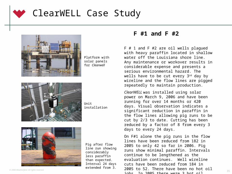
F #1 and F #2
F # 1 and F #2 are oil wells plagued with heavy paraffin located in shallow water off the Louisiana shore line. Any maintenance or workover results in considerable expense and presents a serious environmental hazard. The wells have to be cut every 3rd day by wireline and the flow lines are pigged repeatedly to maintain production.
ClearWELL was installed using solar power on March 9, 2006 and have been running for over 14 months or 420 days. Visual observation indicates a significant reduction in paraffin in the flow lines allowing pig runs to be cut by 2/3 to date. Cutting has been reduced by a factor of 8 from every 3 days to every 24 days.
On F#1 alone the pig runs in the flow lines have been reduced from 182 in 2005 to only 42 so far in 2006. Pig runs show minimal paraffin. Intervals continue to be lengthened as the evaluation continues. Well wireline cuts have been reduced from 184 in 2005 to 52. There have been no hot oil jobs. In 2005 there were 3 hot oil jobs at $30,000 each. On an annual basis $367,748 is saved at these 2 wells by using ClearWELL.
June 1, 2007
Platform with solar panels for Clearwell
Unit installation
Pig after flow line run showing considerably less paraffin than expected. Interval 24 days extended from 3.
ClearWELL Case Study
© 2006 Weatherford. All rights reserved.36
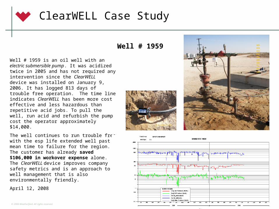
Well # 1959
Well # 1959 is an oil well with an electric submersible pump. It was acidized twice in 2005 and has not required any intervention since the ClearWELL device was installed on January 9, 2006. It has logged 813 days of trouble free operation. The time line indicates ClearWELL has been more cost effective and less hazardous than repetitive acid jobs. To pull the well, run acid and refurbish the pump cost the operator approximately $14,000.
The well continues to run trouble free with the esp life extended well past mean time to failure for the region. The customer has already saved $106,000 in workover expense alone. The ClearWELL device improves company safety metrics and is an approach to well management that is also environmentally friendly.
April 12, 2008
The production curve to the right shows that gas (~75 mcfd) and oil( ~10 bbld) have held steady since 1/9/06. Water
production is ~ 500 bbld .
ClearWELL Case Study
© 2006 Weatherford. All rights reserved.37
Well Application Parameters
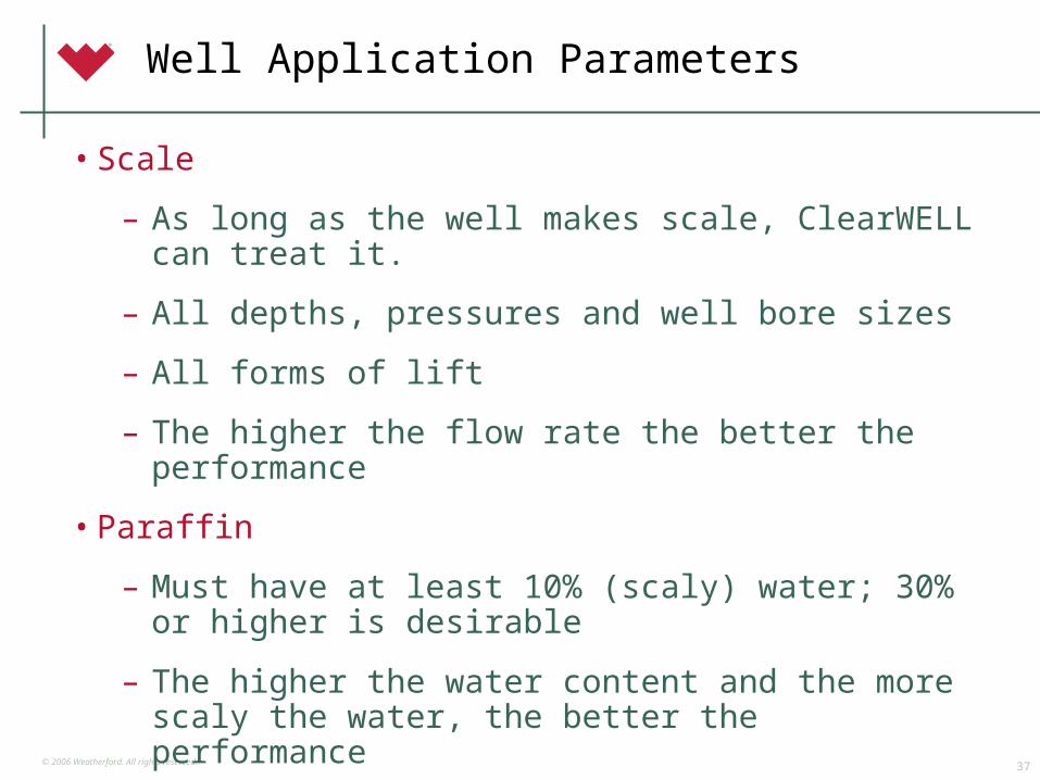
• Scale
– As long as the well makes scale, ClearWELL can treat it.
– All depths, pressures and well bore sizes
– All forms of lift
– The higher the flow rate the better the performance
• Paraffin
– Must have at least 10% (scaly) water; 30% or higher is desirable
– The higher the water content and the more scaly the water, the better the performance
© 2006 Weatherford. All rights reserved.38
Power Requirements
• ClearWELL is a low power device ~ 35 watts standard unit
• Power source options:
• AC source typically 110 or 220 volts
• Generator
• Solar panels & inverter
• Power source range:
• 87 – 240 volts
• 47-63 Hz
© 2006 Weatherford. All rights reserved.39
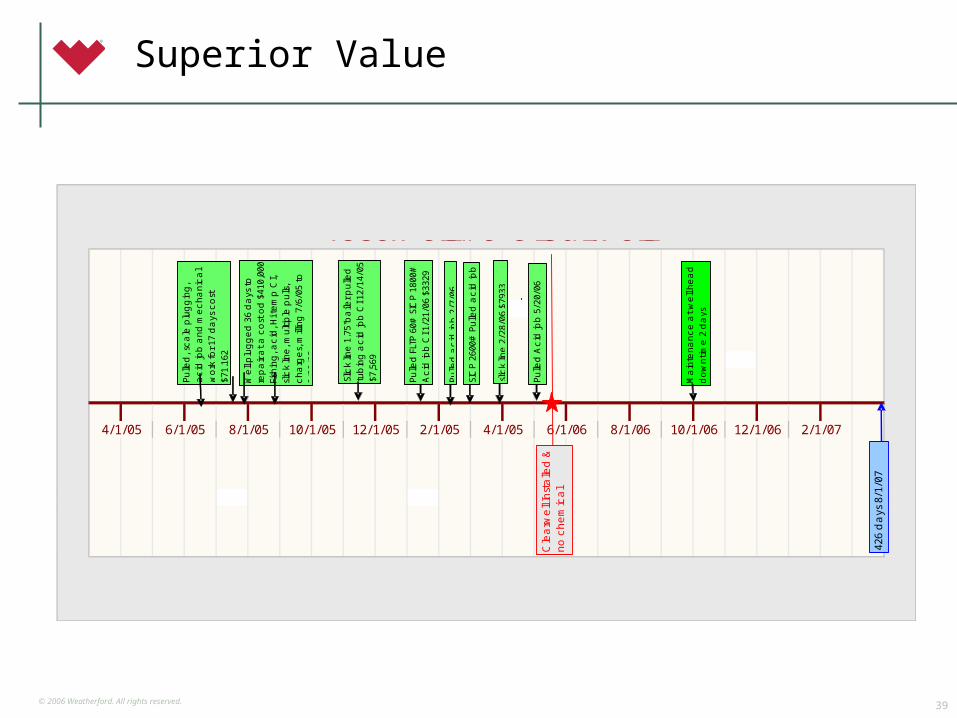
Superior Value
8/1/06 10/1/06 12/1/06 2/1/074/1/05 6/1/0612/1/05 2/1/054/1/05 6/1/05 8/1/05 10/1/05
Test Well #9 Clearwell
Cle
arw
ell
Inst
alle
d &
no
che
mic
al
5/23
/06
426
da
ys 8
/1/0
7
Pulle
d, s
ca
le p
lug
gin
g,
ac
id jo
b a
nd
me
cha
nic
al
wo
rk fo
r 17
da
ys c
ost
$7
1,16
2
We
ll p
lug
ge
d 3
6 d
ays
to
re
pa
ir a
t a
co
st o
d $
410,
000
Fish
ing
, ac
id, H
i te
mp
CI,
slic
k lin
e, m
ulti
ple
pulls
, c
ha
rge
s, m
illin
g 7
/6/0
5 to
8/
28/0
5
Slic
k lin
e 1
.75"
ba
iler p
ulle
d
tub
ing
ac
id jo
b C
I 12/
14/0
5 $7
,569
Pulle
d,a
cid
job
2/7
/06
slic
k lin
e 2
/28/
06 $
7933
SIC
P 2
600#
Pulle
d a
cid
job
Pulle
d A
cid
job
5/2
0/06
Acid scheduled every 7 to 10 days; stopped 5/23/06Operator admits well scales & plugs within 30-40 days7/6/05-8/28/05 lost production not included in $ savings
Pulle
d F
LTP 6
0# S
ICP 1
800#
A
cid
job
CI 1
/21/
06 $
3329
Ma
inte
na
nc
e a
t w
ell
he
ad
-d
ow
ntim
e 2
da
ys

© 2006 Weatherford. All rights reserved.40

© 2006 Weatherford. All rights reserved.41
Capillary Technologies Advanced Technology and Services for Safer and More Effective Production Enhancement

© 2006 Weatherford. All rights reserved.42
Capillary Applications
• Liquid Loading
• Corrosion Control
• Scale Control
• Salt Control
• Paraffin Control
• H2S Control
• Combination Products
© 2006 Weatherford. All rights reserved.43
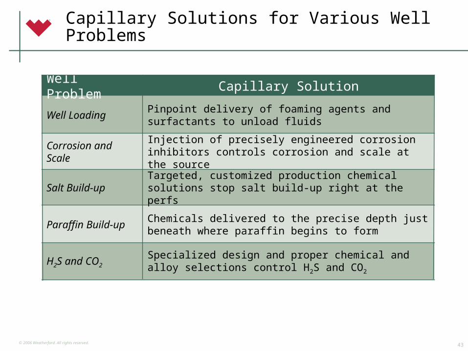
Capillary Solutions for Various Well Problems
Specialized design and proper chemical and alloy selections control H2S and CO2
H2S and CO2
Chemicals delivered to the precise depth just beneath where paraffin begins to form
Paraffin Build-up
Targeted, customized production chemical solutions stop salt build-up right at the perfs
Salt Build-up
Injection of precisely engineered corrosion inhibitors controls corrosion and scale at the source
Corrosion and Scale
Pinpoint delivery of foaming agents and surfactants to unload fluids
Well Loading
Capillary SolutionWell Problem
© 2006 Weatherford. All rights reserved.44
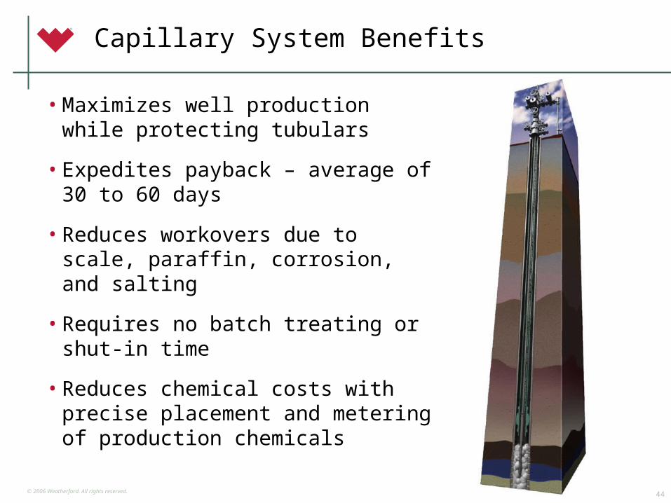
Capillary System Benefits
• Maximizes well production while protecting tubulars
• Expedites payback – average of 30 to 60 days
• Reduces workovers due to scale, paraffin, corrosion, and salting
• Requires no batch treating or shut-in time
• Reduces chemical costs with precise placement and metering of production chemicals

© 2006 Weatherford. All rights reserved.45
Capillary System Benefits cont.
• Saves on downtime with continuous chemical delivery at the perforations
• Installs easily in live wells in just 3 to 4 hours
• Provides adjustable chemical volumes for changing production rates
• Enables chemical supplier to custom blend multi-phase chemical treatments to meet specific needs
© 2006 Weatherford. All rights reserved.46
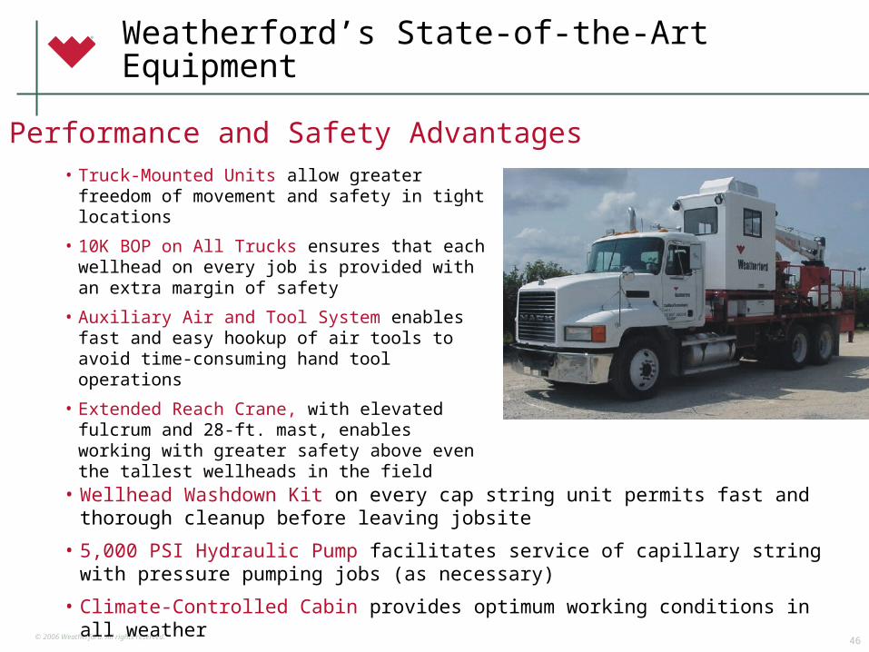
Weatherford’s State-of-the-Art Equipment
• Truck-Mounted Units allow greater freedom of movement and safety in tight locations
• 10K BOP on All Trucks ensures that each wellhead on every job is provided with an extra margin of safety
• Auxiliary Air and Tool System enables fast and easy hookup of air tools to avoid time-consuming hand tool operations
• Extended Reach Crane, with elevated fulcrum and 28-ft. mast, enables working with greater safety above even the tallest wellheads in the field
Performance and Safety Advantages
• Wellhead Washdown Kit on every cap string unit permits fast and thorough cleanup before leaving jobsite
• 5,000 PSI Hydraulic Pump facilitates service of capillary string with pressure pumping jobs (as necessary)
• Climate-Controlled Cabin provides optimum working conditions in all weather
© 2006 Weatherford. All rights reserved.47
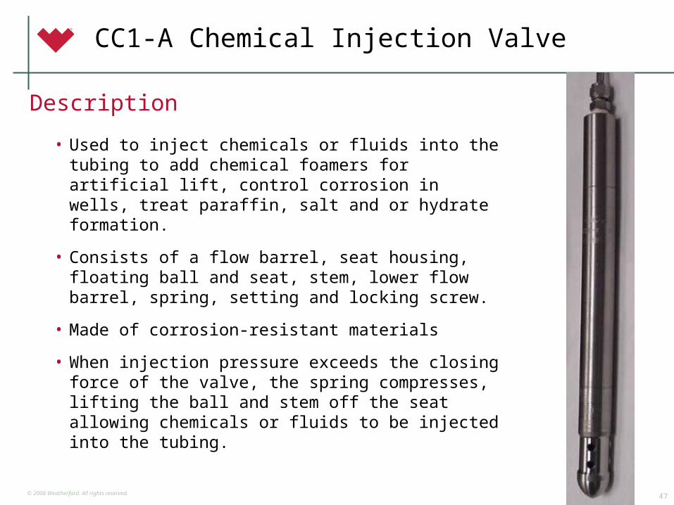
CC1-A Chemical Injection Valve
• Used to inject chemicals or fluids into the tubing to add chemical foamers for artificial lift, control corrosion in wells, treat paraffin, salt and or hydrate formation.
• Consists of a flow barrel, seat housing, floating ball and seat, stem, lower flow barrel, spring, setting and locking screw.
• Made of corrosion-resistant materials
• When injection pressure exceeds the closing force of the valve, the spring compresses, lifting the ball and stem off the seat allowing chemicals or fluids to be injected into the tubing.
Description
© 2006 Weatherford. All rights reserved.48
CC1-A Chemical Injection Valve
• Prevents chemical siphoning
• Prevents sand plugging
• Prevents gas back-flow
• Controls rate of injection
• Delivers reliable performance
• Calibrates to well conditions
• Adjusts easily on location
• Installs easily
Benefits
© 2006 Weatherford. All rights reserved.49
Is Your Well a Capillary Application?
© 2006 Weatherford. All rights reserved.50
Classic Symptoms of Prime Candidates for Capillary Injection
• Well begins to sweep on the charts
• Tubing pressure drops below critical level
• Liquid falls back
• Well loads up, falls off production
• Well unloads when shutting in, drooping soap sticks or batch treating

© 2006 Weatherford. All rights reserved.51
COLEMAN EQUATIONCritical Flow Rates vs Tbing ID and Ftp
Liquid Phase: SG=1.08; (9 ppg) - Avg Oil Field Brine
10
100
1,000
10,000
1 10 100 1,000 10,000
Flowing Tubing Pressure (psi)
Flo
w R
ate
(M
CF
D)
1-1/4", Includes Z=0.95 and20% safety factor
2-3/8", Includes Z=0.95 and20% safety factor
2-7/8", Includes Z=0.95 and20% safety factor
1-1/4", Includes Z=0.95
2-3/8", Includes Z=0.95
2-7/8"", Includes Z=0.95
Coleman Equation Includes Z = 0.95Includes 20% Safety
…. More Useful with Ftp<1,000 psi
TURNER EQUATIONCritical Flow Rates vs Tbing ID and Ftp
Liquid Phase: SG=1.08; (9 ppg) - Avg Oil Field Brine
10
100
1,000
10,000
1 10 100 1,000 10,000
Flowing Tubing Pressure (psi)
Flo
w R
ate
(M
CF
D)
1-1/4", Includes Z=0.95 and20% safety factor
2-3/8", Includes Z=0.95 and20% safety factor
2-7/8", Includes Z=0.95 and20% safety factor
1-1/4", Includes Z=0.95
2-3/8", Includes Z=0.95
2-7/8"", Includes Z=0.95
Turner Equation Includes Z = 0.95Includes 20% Safety
…. More Useful with Ftp>1,000 psi
Critical Flow Rate Calculations―Critical Decisions
© 2006 Weatherford. All rights reserved.52
Liquid Loading: Coleman EquationEffects of Proper Foamer Application
Foam Cluster Apparent Density = 6 lbm/ft3
Foam Cluster Water Surface Tension = 20 dynes/cm
Standard Assumptions that “Simplify” the Turner Equation to the Coleman Equation:
Vc = 1.593σ1/4(ρLiquid-ρGas)1/4
ρGas1/2
TurnerEquation
60 dynes/cm surface tension for water20 dynes/cm surface tension for condensate67 lbm/ft3 water density45 lbm/ft3 condensate density0.6 gas gravity120 oF gas temperature20% upward adjustment Fit his empirical data
Vc = C(ρLiquid-0.0031p)1/4
(0.0031p)1/2
SimplifiedColeman Equation
Colemaneliminates 20 percent adjustment
Lower PressuresFOAM CASE
Vc reduces by factor of +/- 2.5 at 100 PSI22.8 to 9.3 ft/sec
Note: No friction considered for additional foam viscosity
C = 4.434, waterC= 3.369,condensate,p<=1,000 PSIC = 3.369, FOAM
Gas Flow
FOAM Droplet Cluster
Gravity
© 2006 Weatherford. All rights reserved.53
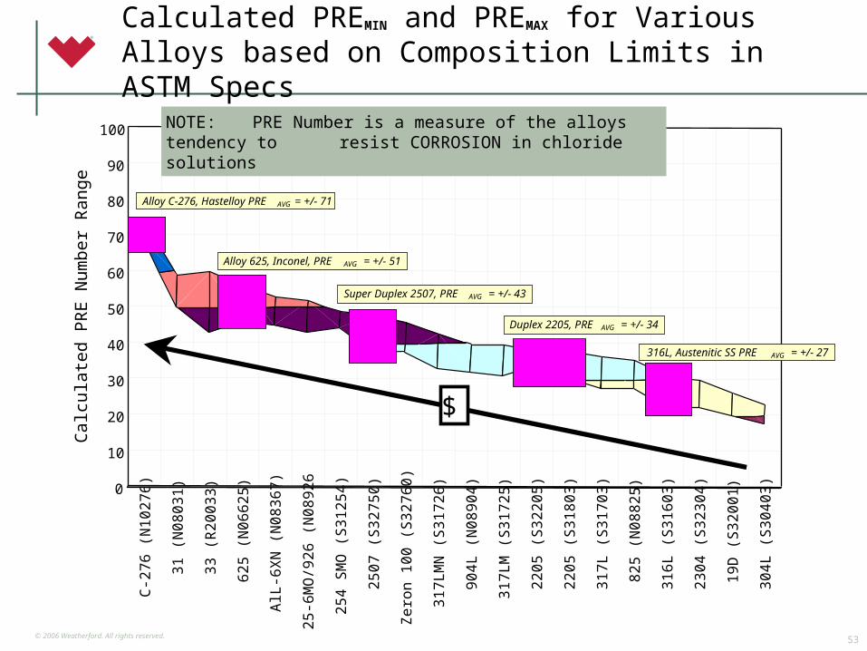
Calculated PREMIN and PREMAX for Various Alloys based on Composition Limits in ASTM Specs
C-27
6 (N
1027
6)
31 (N
0803
1)
33 (R
2003
3)
625
(N06
625)
AlL-
6XN
(N08
367)
25-6
MO
/926
(N08
926
254
SMO
(S31
254)
2507
(S32
750)
Zero
n 10
0 (S
3276
0)
317L
MN
(S31
726)
904L
(N08
904)
317L
M (S
3172
5)
2205
(S32
205)
2205
(S31
803)
317L
(S31
703)
825
(N08
825)
316L
(S31
603)
2304
(S32
304)
19D
(S32
001)
304L
(S30
403)
0
10
20
30
40
50
60
70
80
90
100
Cal
cula
ted
PR
E N
umbe
r R
ange
NOTE: PRE Number is a measure of the alloys tendency to resist CORROSION in chloride solutions
Alloy 625, Inconel, PRE AVG = +/- 51
Super Duplex 2507, PRE AVG = +/- 43
Duplex 2205, PRE AVG = +/- 34
316L, Austenitic SS PRE AVG = +/- 27
$
Alloy C-276, Hastelloy PRE AVG = +/- 71

© 2006 Weatherford. All rights reserved.54
Selection GuideCorrosion Resistant Alloy Tubulars in Gas Wells
CO2, H2S, Chlorides, Temperature….Which one is most important?
From Schillmoller, 1989 … Selection of Corrosion-Resistant Alloy Tubulars for Offshore Applications
0.001
0.01
0.1
1
10
100
1000
10000
100000
0.001 0.01 0.1 1 10 100 1000 10000 100000
Alloy 625
Super Duplex 2507
Duplex 2205
Alloy 300 series
Partial Pressure of H2S psia
Par
tial P
ress
ure
of C
O2
psia
© 2006 Weatherford. All rights reserved.55
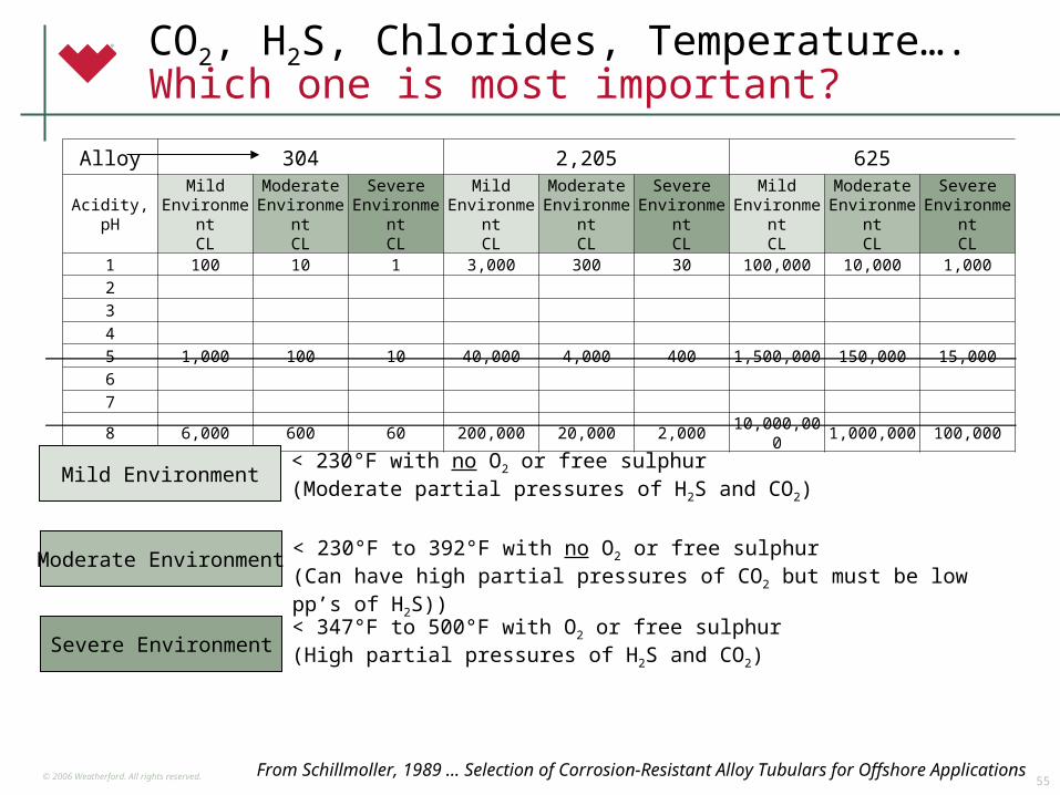
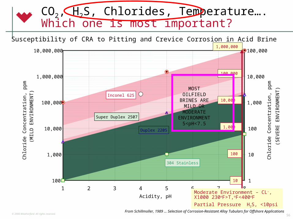
CO2, H2S, Chlorides, Temperature….Which one is most important?
Alloy 304 2,205 625
Acidity, pHMild
EnvironmentCL
Moderate Environment
CL
Severe Environment
CL
Mild Environment
CL
Moderate Environment
CL
Severe Environment
CL
Mild Environment
CL
Moderate Environment
CL
Severe Environment
CL1 100 10 1 3,000 300 30 100,000 10,000 1,0002
3
4
5 1,000 100 10 40,000 4,000 400 1,500,000 150,000 15,0006
7
8 6,000 600 60 200,000 20,000 2,000 10,000,000 1,000,000 100,000
Severe Environment
Moderate Environment
Mild Environment< 230°F with no O2 or free sulphur(Moderate partial pressures of H2S and CO2)
< 230°F to 392°F with no O2 or free sulphur(Can have high partial pressures of CO2 but must be low pp’s of H2S))
< 347°F to 500°F with O2 or free sulphur(High partial pressures of H2S and CO2)
From Schillmoller, 1989 … Selection of Corrosion-Resistant Alloy Tubulars for Offshore Applications
© 2006 Weatherford. All rights reserved.56
304 Stainless
CO2, H2S, Chlorides, Temperature….Which one is most important?
Susceptibility of CRA to Pitting and Crevice Corrosion in Acid Brine
100
1,000
10,000
100,000
1,000,000
10,000,000
1 2 3 4 5 6 7 8
Acidity, pH
Ch
lorid
e C
on
cen
tra
tion
, p
pm
(MIL
D E
NV
IRO
NM
EN
T)
1
10
100
1,000
10,000
100,000
Ch
lorid
e C
on
cen
tra
tion
, p
pm
(SE
VE
RE
EN
VIR
ON
ME
NT
)
10
100
1,000
10,000
100,000
1,000,000
Super Duplex 2507
MOST OILFIELD
BRINES AREMILD OR
MODERATE ENVIRONMEN
T5<pH<7.5
Inconel 625
Duplex 2205
From Schillmoller, 1989 … Selection of Corrosion-Resistant Alloy Tubulars for Offshore Applications
Moderate Environment – CL-, X1000 230oF>T,oF<400oF
Partial Pressure H2S, <10psi
© 2006 Weatherford. All rights reserved.57
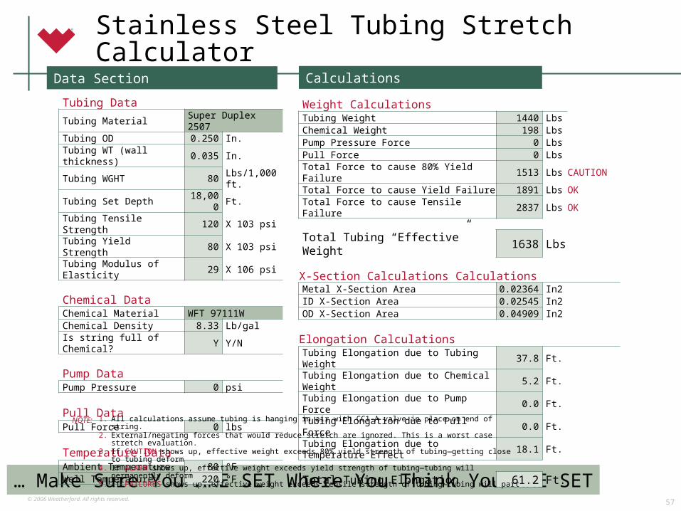
Stainless Steel Tubing Stretch Calculator
… Make Sure You ARE SET Where You Think You ARE SET
Tubing DataTubing Material Super Duplex 2507Tubing OD 0.250 In.Tubing WT (wall thickness) 0.035 In.Tubing WGHT 80 Lbs/1,000 ft.Tubing Set Depth 18,000 Ft.Tubing Tensile Strength 120 X 103 psiTubing Yield Strength 80 X 103 psiTubing Modulus of Elasticity 29 X 106 psi
Chemical DataChemical Material WFT 97111WChemical Density 8.33 Lb/galIs string full of Chemical? Y Y/N
Pump DataPump Pressure 0 psi
Pull DataPull Force 0 lbs
Temperature DataAmbient Temperature 80 °FWell Temperature 220 °F
Weight CalculationsTubing Weight 1440 LbsChemical Weight 198 LbsPump Pressure Force 0 LbsPull Force 0 LbsTotal Force to cause 80% Yield Failure 1513 Lbs CAUTIONTotal Force to cause Yield Failure 1891 Lbs OKTotal Force to cause Tensile Failure 2837 Lbs OK
Total Tubing “Effective” Weight 1638 Lbs
X-Section Calculations CalculationsMetal X-Section Area 0.02364 In2ID X-Section Area 0.02545 In2OD X-Section Area 0.04909 In2
Elongation CalculationsTubing Elongation due to Tubing Weight 37.8 Ft.Tubing Elongation due to Chemical Weight 5.2 Ft.Tubing Elongation due to Pump Force 0.0 Ft.Tubing Elongation due to Pull Force 0.0 Ft.Tubing Elongation due to Temperature Effect 18.1 Ft.
Total Tubing Elongation 61.2 Ft.
Data Section Calculations
1. All calculations assume tubing is hanging in air with CC1-A valve in place on end of string.2. External/negating forces that would reduce stretch are ignored. This is a worst case stretch evaluation.3. If CAUTION shows up, effective weight exceeds 80% yield strength of tubing—getting close to tubing deform4. If ALARM shows up, effective weight exceeds yield strength of tubing—tubing will permanently deform5. If FAILURES shows up, effective weight exceeds tensile strength of tubing—tubing will part
NOTE:
© 2006 Weatherford. All rights reserved.58
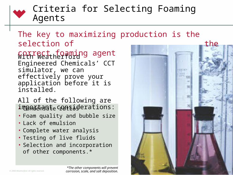
Criteria for Selecting Foaming Agents
• Condensate ratios• Foam quality and bubble size• Lack of emulsion• Complete water analysis• Testing of live fluids• Selection and incorporation of
other components.**The other components will prevent
corrosion, scale, and salt deposition.
The key to maximizing production is the selection of the correct foaming agent
With Weatherford Engineered Chemicals’ CCT simulator, we can effectively prove your application before it is installed.
All of the following are important considerations:
58
© 2006 Weatherford. All rights reserved.59
Weatherford Engineered Chemistry (WEC)
Proven formulas including biocides used for refinery processes and well workover applications. W-Cap certified versions available.
Specialties
Dispersants, penitrants, pour point depressants, crystal modifier. W-Cap certified versions available.
Paraffin Treating
Versions available for continuous or formation squeeze. Hot/cold climate stable. W-Cap certified versions available.
Scale Inhibitors
A broad range to treat water in oil emulsions. W-Cap certified versions available.
Emulsion Breakers
Complete line of non-regeneratative scavengers. W-Cap Certified versions available.
H2S Scavengers
Oil- and water-based, continuous or batch applied Inhibitors designed for a wide range of systems and conditions. W-Cap certified versions available.
Corrosion Inhibitors
AdvantagesProduct Category
© 2006 Weatherford. All rights reserved.60
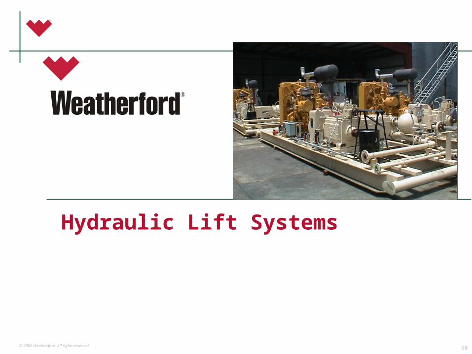
Hydraulic Lift Systems

© 2006 Weatherford. All rights reserved.61
Global Perspective
• The broadest range of quality products and services in the industry
• Fit-for-purpose
• A wealth of global experience
• A commitment to continuous improvements, bringing business benefits to our clients
• A level of service that meets or exceeds the business goals of our clients
• A desire to be partners and share in the success with our clients
© 2006 Weatherford. All rights reserved.62
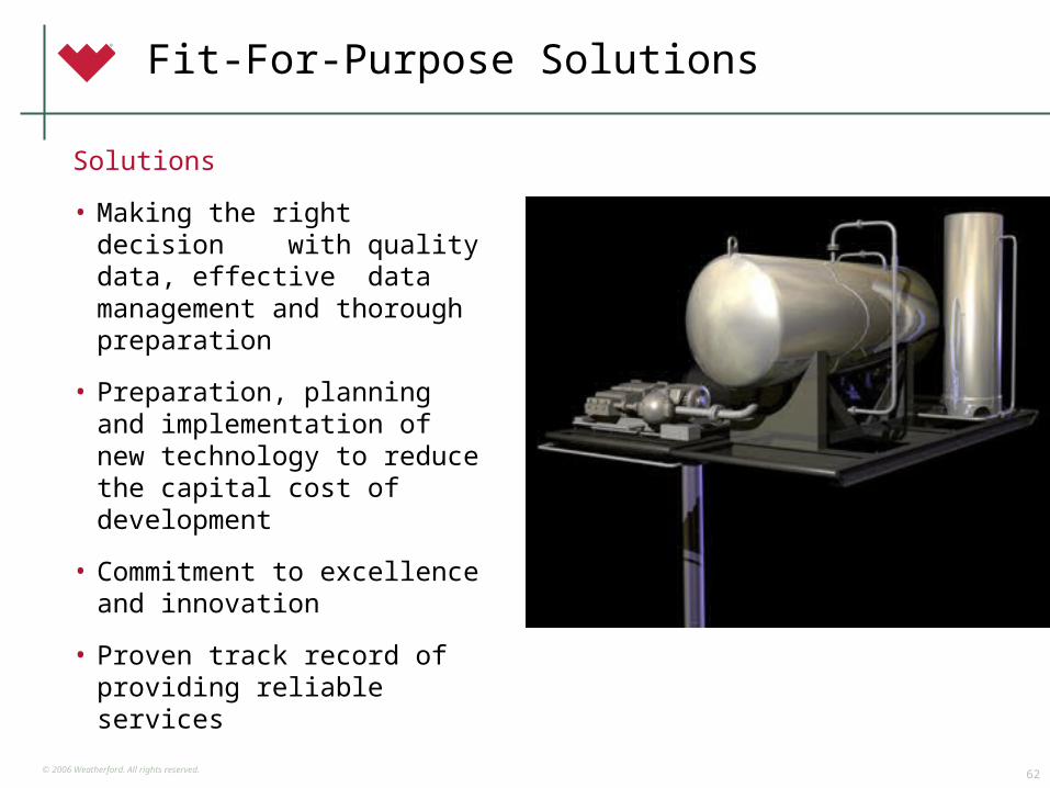
Fit-For-Purpose Solutions
Solutions
• Making the right decision with quality data, effective data management and thorough preparation
• Preparation, planning and implementation of new technology to reduce the capital cost of development
• Commitment to excellence and innovation
• Proven track record of providing reliable services
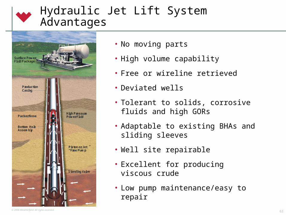
© 2006 Weatherford. All rights reserved.63
Hydraulic Jet Lift System Advantages
• No moving parts
• High volume capability
• Free or wireline retrieved
• Deviated wells
• Tolerant to solids, corrosive fluids and high GORs
• Adaptable to existing BHAs and sliding sleeves
• Well site repairable
• Excellent for producing viscous crude
• Low pump maintenance/easy to repair
ProductionCasing
High PressurePower FluidPacker Nose
Bottom HoleAssembly
Piston or Jet“Free Pump ”
Standing Valve
Surface PowerFluid Package
ProductionCasing
High PressurePower FluidPacker Nose
Bottom HoleAssembly
Piston or Jet“Free Pump ”
Standing Valve
Surface PowerFluid Package
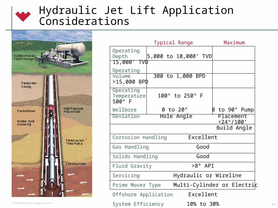
© 2006 Weatherford. All rights reserved.64
Hydraulic Jet Lift Application Considerations
Typical Range Maximum
OperatingDepth 5,000 to 10,000’ TVD 15,000’ TVD
OperatingVolume 300 to 1,000 BPD >15,000 BPD
OperatingTemperature 100° to 250° F 500° F
Wellbore 0 to 20° 0 to 90° Pump
Deviation Hole Angle Placement <24°/100’ Build Angle
Corrosion Handling Excellent
Gas Handling Good
Solids Handling Good
Fluid Gravity >8° API
Servicing Hydraulic or Wireline
Prime Mover Type Multi-Cylinder or Electric
Offshore Application Excellent
System Efficiency 10% to 30%
ProductionCasing
High PressurePower FluidPacker Nose
Bottom HoleAssembly
Piston or Jet“Free Pump ”
Standing Valve
Surface PowerFluid Package
ProductionCasing
High PressurePower FluidPacker Nose
Bottom HoleAssembly
Piston or Jet“Free Pump ”
Standing Valve
Surface PowerFluid Package
© 2006 Weatherford. All rights reserved.65
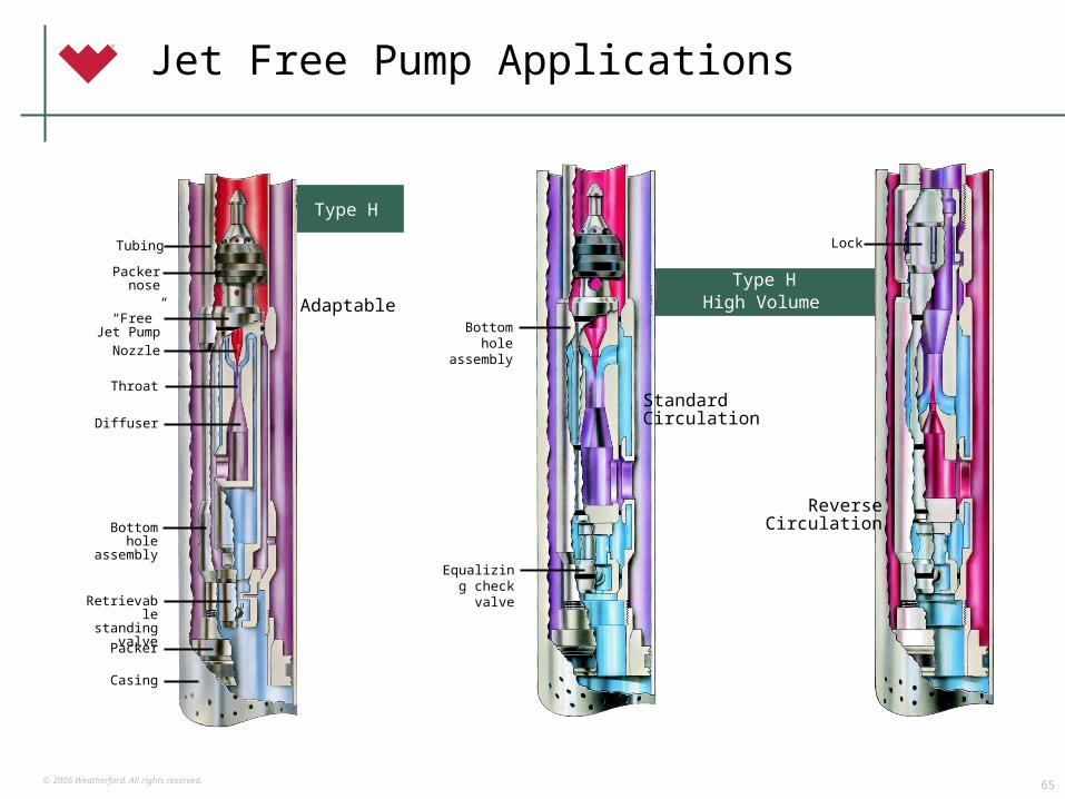
Type HHigh Volume
Bottom hole assembly
StandardCirculation
Jet Free Pump Applications
Type H
Tubing
Packer nose
“Free” Jet Pump
Nozzle
Throat
Diffuser
Bottom hole
assembly
Retrievable standing
valve
Packer
Casing
Adaptable
Equalizing check valve
ReverseCirculation
Lock
© 2006 Weatherford. All rights reserved.66
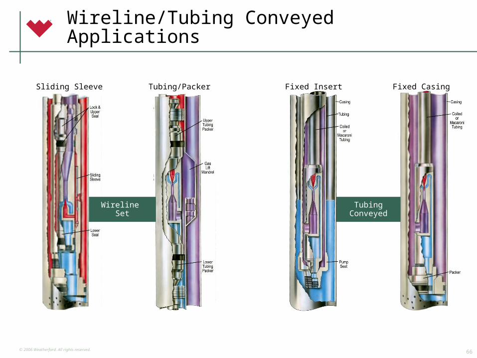
Wireline/Tubing Conveyed Applications
Wireline Set
Tubing Conveyed
Sliding Sleeve Tubing/Packer Fixed Insert Fixed Casing
© 2006 Weatherford. All rights reserved.67
Hydraulic Piston LiftSystem Advantages
• Often free or wireline retrievable
• Positive displacement—strong drawdown
• Double-acting high-volumetric efficiency
• Good depth/volume capability— +15,000 ft.
• Deviated wells
• Multi-well production from single surface package
• Horsepower efficiency
© 2006 Weatherford. All rights reserved.68
*SpecialAnalysisRequired
Hydraulic Piston LiftApplication Considerations
ProductionCasing
High PressurePower Fluid
Packer Nose
Bottom HoleAssembly
Piston or Jet“Free Pump ”
Standing Valve
Surface PowerFluid Package
ProductionCasing
High PressurePower Fluid
Packer Nose
Bottom HoleAssembly
Piston or Jet“Free Pump ”
Standing Valve
Surface PowerFluid Package
Typical Range Maximum
OperatingDepth 7,500 to 10,000’ TVD 17,000’ TVD
OperatingVolume 5 to 500 BPD 4,000 BPD
OperatingTemperature 100° to 250° F 500° F
Wellbore 0 to 20° 0 to 90° Pump
Deviation Landed Pump Placement <15°/100’ Build Angle
Corrosion Handling Good
Gas Handling Fair
Solids Handling Poor
Fluid Gravity >8° API
Servicing Hydraulic or Wireline
Prime Mover Type Multi-Cylinder or Electric
Offshore Application Good
System Efficiency 40% to 50%
© 2006 Weatherford. All rights reserved.69
Basic downhole installations
CasingReturn
ParallelReturn
Free Pump
CasingReturn
Tubing Conveyed
T/T AnnulusReturn
Open Power Fluid Configurations

© 2006 Weatherford. All rights reserved.70
“Free Pump”Pump In and Out Operation
© 2006 Weatherford. All rights reserved.71
Why Weatherford?
• Achievement of a unified, seamless organization through functional integration
• Promotion of the importance of quality improvement
• Recognition of processes necessary for achievement of continuous improvement
• Sharing information on successful quality strategies within the partnership
• Alignment of business strategy and objectives with those of our customers
• Establishment of performance criteria to measure process improvement

© 2006 Weatherford. All rights reserved.72
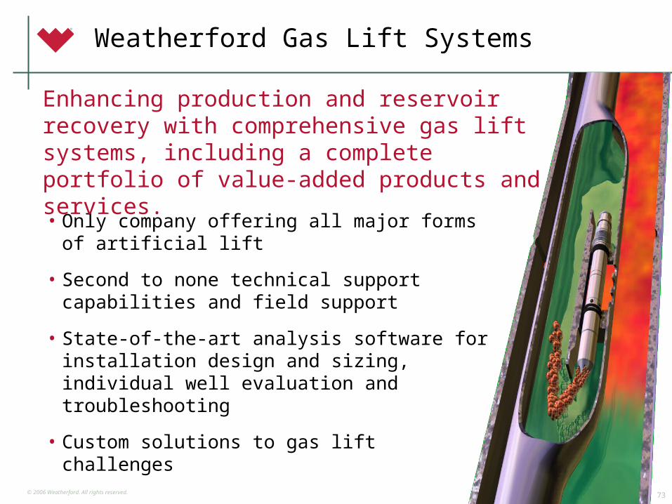
Gas Lift Systems
© 2006 Weatherford. All rights reserved.73
Weatherford Gas Lift Systems
• Only company offering all major forms of artificial lift
• Second to none technical support capabilities and field support
• State-of-the-art analysis software for installation design and sizing, individual well evaluation and troubleshooting
• Custom solutions to gas lift challenges
Enhancing production and reservoir recovery with comprehensive gas lift systems, including a complete portfolio of value-added products and services.
© 2006 Weatherford. All rights reserved.74
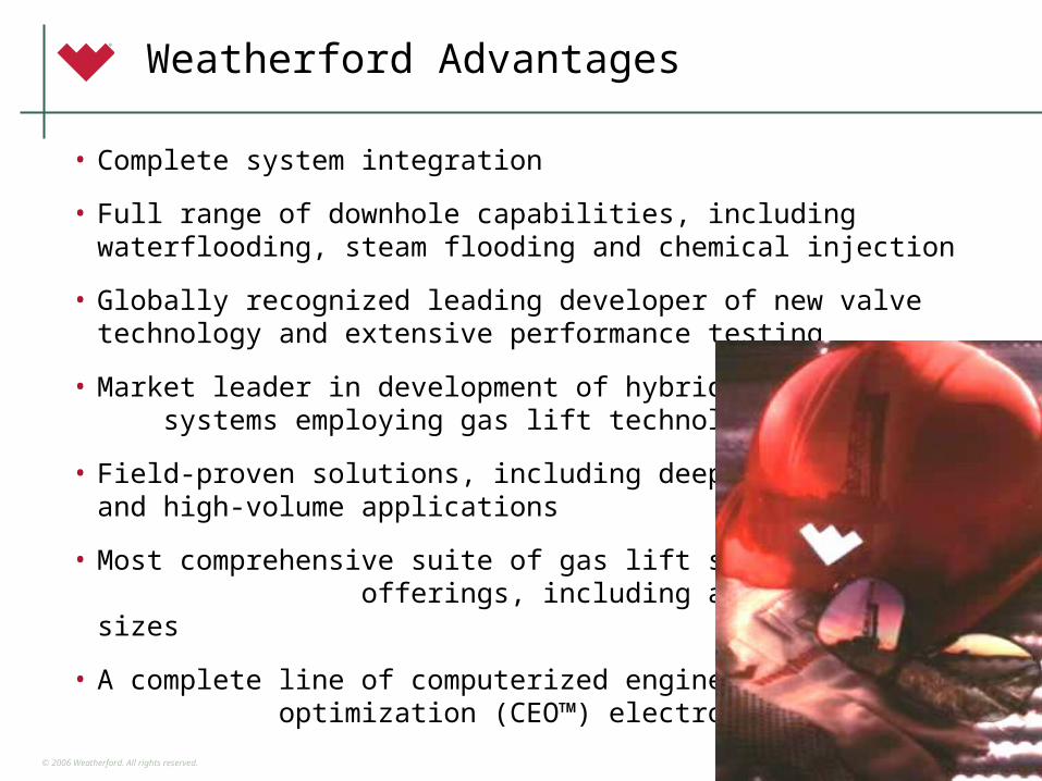
Weatherford Advantages
• Complete system integration
• Full range of downhole capabilities, including waterflooding, steam flooding and chemical injection
• Globally recognized leading developer of new valve technology and extensive performance testing
• Market leader in development of hybrid lift systems employing gas lift technologies
• Field-proven solutions, including deepwater and high-volume applications
• Most comprehensive suite of gas lift solution offerings, including a wide range of sizes
• A complete line of computerized engineering optimization (CEO™) electronic controllers
© 2006 Weatherford. All rights reserved.75
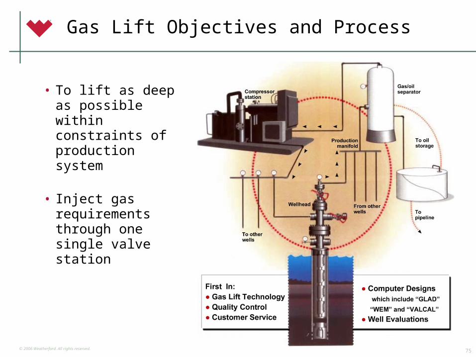
Gas Lift Objectives and Process
• To lift as deep as possible within constraints of production system
• Inject gas requirements through one single valve station
© 2006 Weatherford. All rights reserved.76
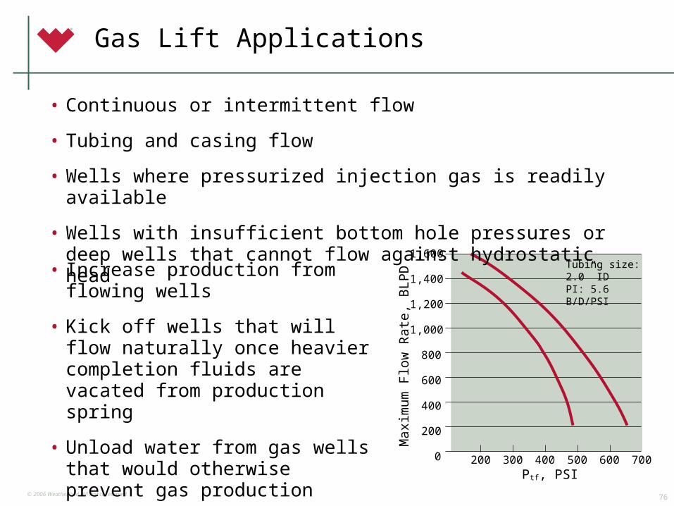
Gas Lift Applications
• Increase production from flowing wells
• Kick off wells that will flow naturally once heavier completion fluids are vacated from production spring
• Unload water from gas wells that would otherwise prevent gas production
1,600
1,400
1,200
1,000
800
600
400
200
0 200 300 400 500 600 700
Max
imum
Flo
w R
ate
, B
LPD
Ptf, PSI
Tubing size: 2.0” IDPI: 5.6 B/D/PSI
• Continuous or intermittent flow
• Tubing and casing flow
• Wells where pressurized injection gas is readily available
• Wells with insufficient bottom hole pressures or deep wells that cannot flow against hydrostatic head
© 2006 Weatherford. All rights reserved.77
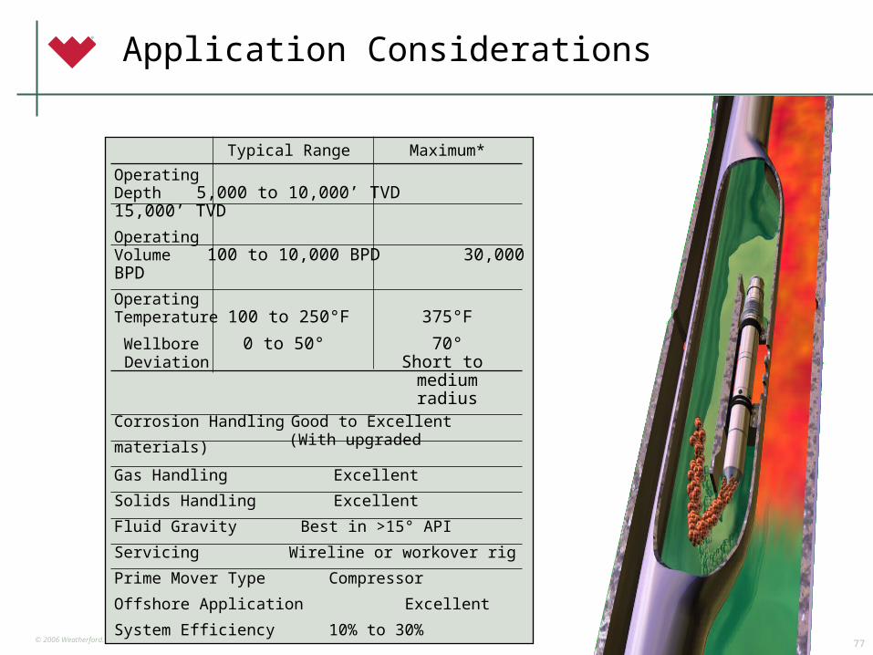
Application Considerations
Typical Range Maximum*
OperatingDepth 5,000 to 10,000’ TVD 15,000’ TVD
OperatingVolume 100 to 10,000 BPD 30,000 BPD
OperatingTemperature 100 to 250°F 375°F
Wellbore 0 to 50° 70° Deviation Short to
mediumradius
Corrosion Handling Good to Excellent (With upgraded materials)
Gas Handling Excellent
Solids Handling Excellent
Fluid Gravity Best in >15° API
Servicing Wireline or workover rig
Prime Mover Type Compressor
Offshore Application Excellent
System Efficiency 10% to 30%
© 2006 Weatherford. All rights reserved.78
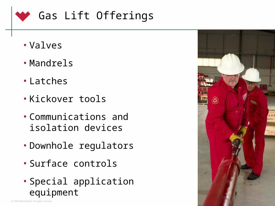
Gas Lift Offerings
• Valves
• Mandrels
• Latches
• Kickover tools
• Communications and isolation devices
• Downhole regulators
• Surface controls
• Special application equipment
© 2006 Weatherford. All rights reserved.79
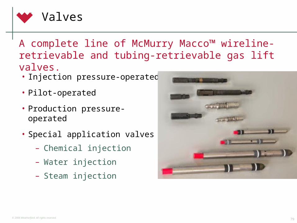
Valves
• Injection pressure-operated
• Pilot-operated
• Production pressure-operated
• Special application valves
– Chemical injection
– Water injection
– Steam injection
A complete line of McMurry Macco™ wireline-retrievable and tubing-retrievable gas lift valves.
© 2006 Weatherford. All rights reserved.80
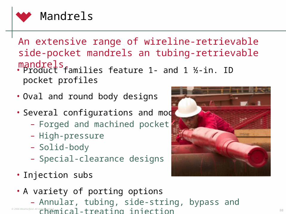
Mandrels
• Product families feature 1- and 1 ½-in. ID pocket profiles
• Oval and round body designs
• Several configurations and models– Forged and machined pocket– High-pressure– Solid-body– Special-clearance designs
• Injection subs
• A variety of porting options– Annular, tubing, side-string, bypass and chemical-
treating injection
An extensive range of wireline-retrievable side-pocket mandrels an tubing-retrievable mandrels.
© 2006 Weatherford. All rights reserved.81
Progressing Cavity Pumps

© 2006 Weatherford. All rights reserved.82
One Weatherford
34,000 people
710 facilities
100 countries
85 manufacturing plants
16 training and R&D facilities
More than…More than…
© 2006 Weatherford. All rights reserved.83
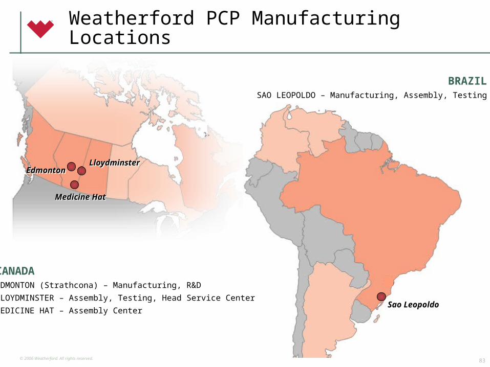
Weatherford PCP Manufacturing Locations
CANADAEDMONTON (Strathcona) – Manufacturing, R&D
LLOYDMINSTER – Assembly, Testing, Head Service Center
MEDICINE HAT – Assembly Center
CANADAEDMONTON (Strathcona) – Manufacturing, R&D
LLOYDMINSTER – Assembly, Testing, Head Service Center
MEDICINE HAT – Assembly Center
BRAZILSAO LEOPOLDO – Manufacturing, Assembly, Testing
BRAZILSAO LEOPOLDO – Manufacturing, Assembly, Testing
Sao Leopoldo
EdmontonEdmontonLloydminsterLloydminster
Medicine HatMedicine Hat
© 2006 Weatherford. All rights reserved.84
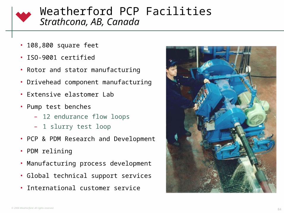
Weatherford PCP FacilitiesStrathcona, AB, Canada
• 108,800 square feet
• ISO-9001 certified
• Rotor and stator manufacturing
• Drivehead component manufacturing
• Extensive elastomer Lab
• Pump test benches
– 12 endurance flow loops
– 1 slurry test loop
• PCP & PDM Research and Development
• PDM relining
• Manufacturing process development
• Global technical support services
• International customer service
© 2006 Weatherford. All rights reserved.85
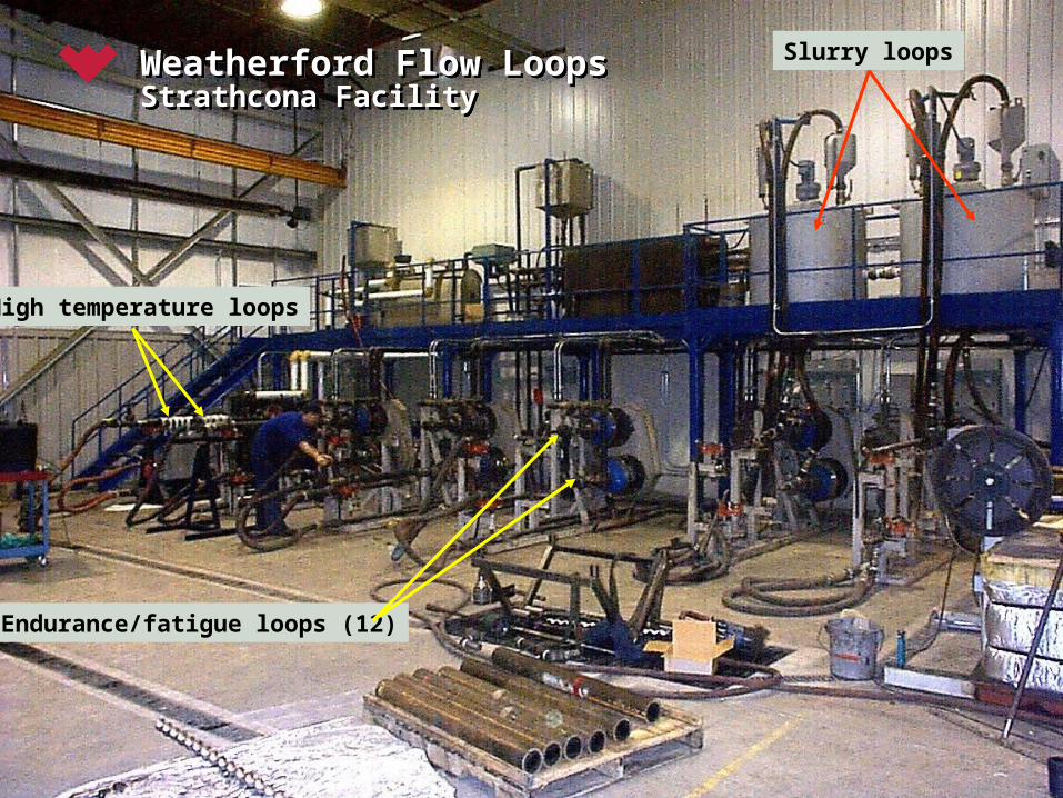
Weatherford Flow LoopsStrathcona FacilityWeatherford Flow LoopsStrathcona Facility
High temperature loops
Slurry loops
Endurance/fatigue loops (12)
© 2006 Weatherford. All rights reserved.86
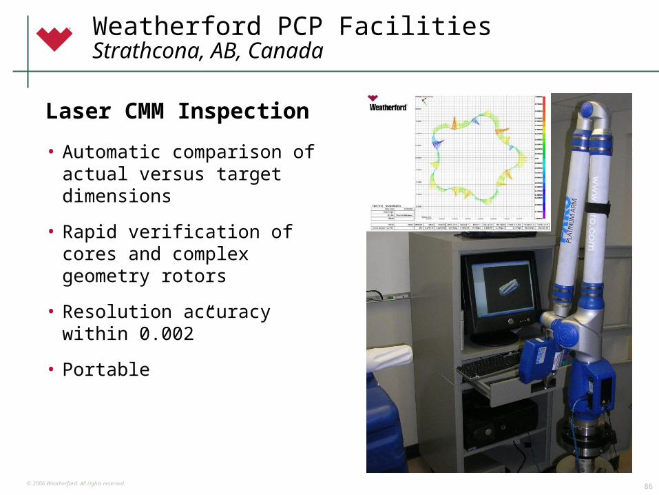
• Automatic comparison of actual versus target dimensions
• Rapid verification of cores and complex geometry rotors
• Resolution accuracy within 0.002”
• Portable
Laser CMM Inspection
Weatherford PCP FacilitiesStrathcona, AB, Canada
© 2006 Weatherford. All rights reserved.87
Weatherford PCP FacilitiesLloydminster, AB, Canada
• 77,700 square feet
• Pump assembly and phasing
• Pump testing
• Drivehead assembly
– Direct
– Hydraulic
• Drivehead testing
• Head repair and service center
• Accessory manufacturing
• Surface transfer pumps
• Drivehead and accessory development
• Canadian technical support
• Canadian customer service
© 2006 Weatherford. All rights reserved.88
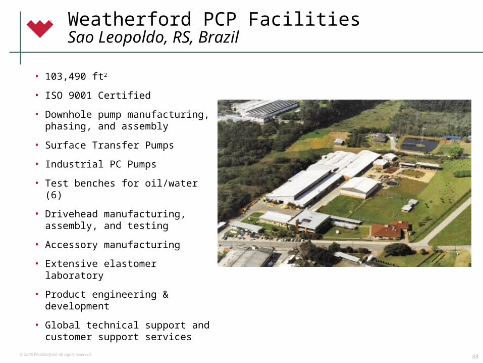
Weatherford PCP FacilitiesSao Leopoldo, RS, Brazil
• 103,490 ft2
• ISO 9001 Certified
• Downhole pump manufacturing, phasing, and assembly
• Surface Transfer Pumps
• Industrial PC Pumps
• Test benches for oil/water (6)
• Drivehead manufacturing, assembly, and testing
• Accessory manufacturing
• Extensive elastomer laboratory
• Product engineering & development
• Global technical support and customer support services
© 2006 Weatherford. All rights reserved.89
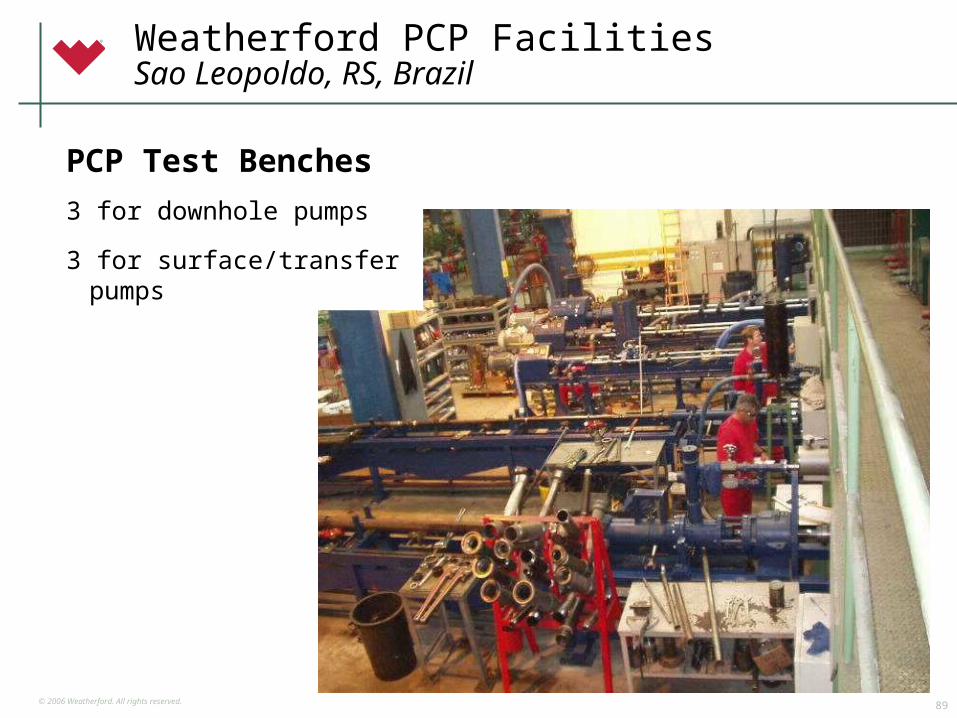
Weatherford PCP FacilitiesSao Leopoldo, RS, Brazil
PCP Test Benches
3 for downhole pumps
3 for surface/transfer pumps
© 2006 Weatherford. All rights reserved.90
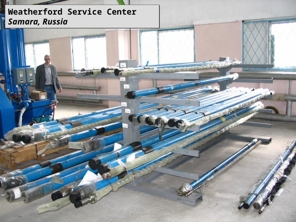
Weatherford Service CenterSamara, RussiaWeatherford Service CenterSamara, Russia
© 2006 Weatherford. All rights reserved.91
Progressing Cavity Pump Technologies
© 2006 Weatherford. All rights reserved.92
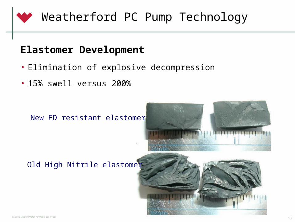
Elastomer Development
• Elimination of explosive decompression
• 15% swell versus 200%
Old High Nitrile elastomer
New ED resistant elastomer
Weatherford PC Pump Technology
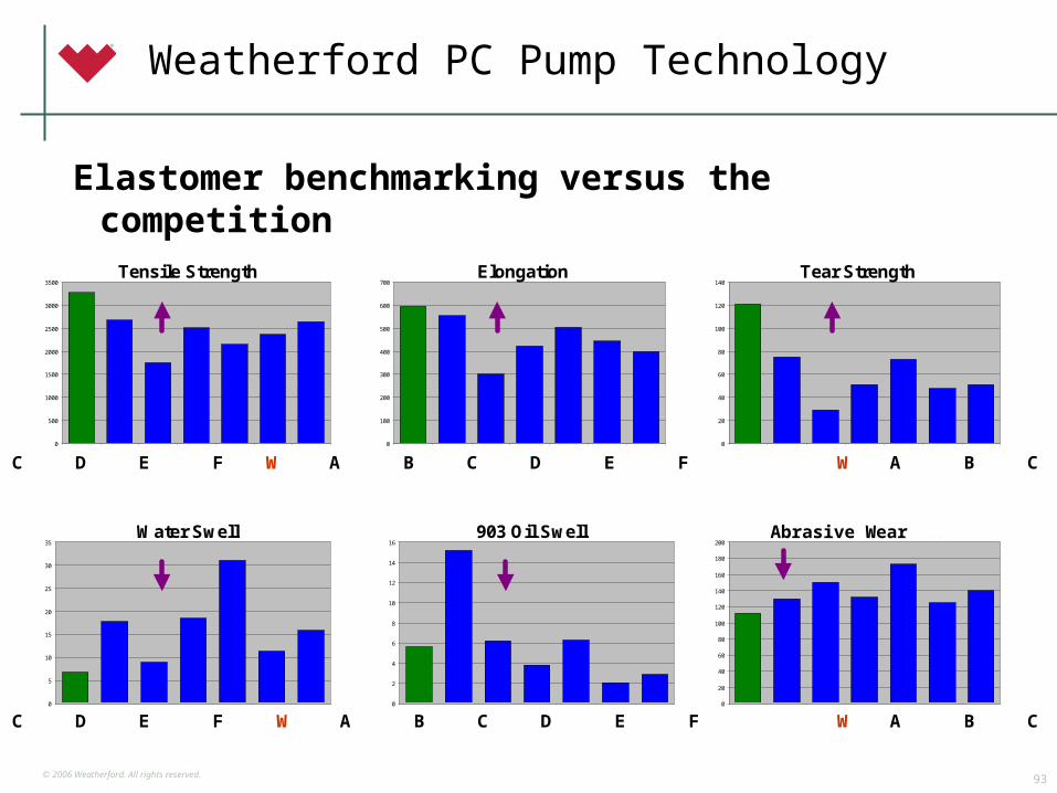
© 2006 Weatherford. All rights reserved.93
Tensile Strength
0
500
1000
1500
2000
2500
3000
3500
WFD 59O ArtemisNO80
GeremiaNBR-M
Kachele 366 Mono A Moyno 102 NetzschNBR01
Elongation
0
100
200
300
400
500
600
700
WFD 59O ArtemisNO80
GeremiaNBR-M
Kachele 366 Mono A Moyno 102 NetzschNBR01
Tear Strength
0
20
40
60
80
100
120
140
WFD 59O ArtemisNO80
GeremiaNBR-M
Kachele 366 Mono A Moyno 102 NetzschNBR01
Water Swell
0
5
10
15
20
25
30
35
WFD 59O Artemis NO80 GeremiaNBR-M
Kachele 366 Mono A Moyno 102 NetzschNBR01
903 Oil Swell
0
2
4
6
8
10
12
14
16
WFD 59O Artemis NO80 GeremiaNBR-M
Kachele 366 Mono A Moyno 102 NetzschNBR01
Abrasion Resistance
0
20
40
60
80
100
120
140
160
180
200
WFD 59O ArtemisNO80
GeremiaNBR-M
Kachele 366 Mono A Moyno 102 NetzschNBR01
Abrasive Wear
W A B C D E F W A B C D E F W A B C D E F
W A B C D E F W A B C D E F W A B C D E F
Weatherford PC Pump Technology
Elastomer benchmarking versus the competition
© 2006 Weatherford. All rights reserved.94
Weatherford PC Pump Technology
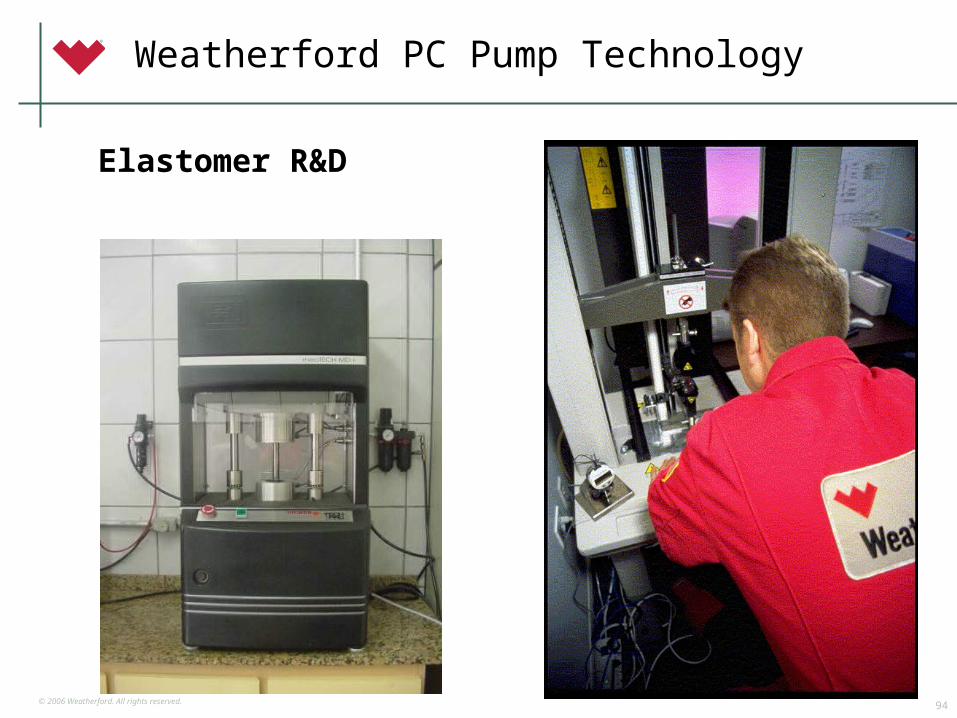
Elastomer R&D

© 2006 Weatherford. All rights reserved.95
Weatherford PC Pump Technology
3-D Non-linear Finite Element Modeling
© 2006 Weatherford. All rights reserved.96
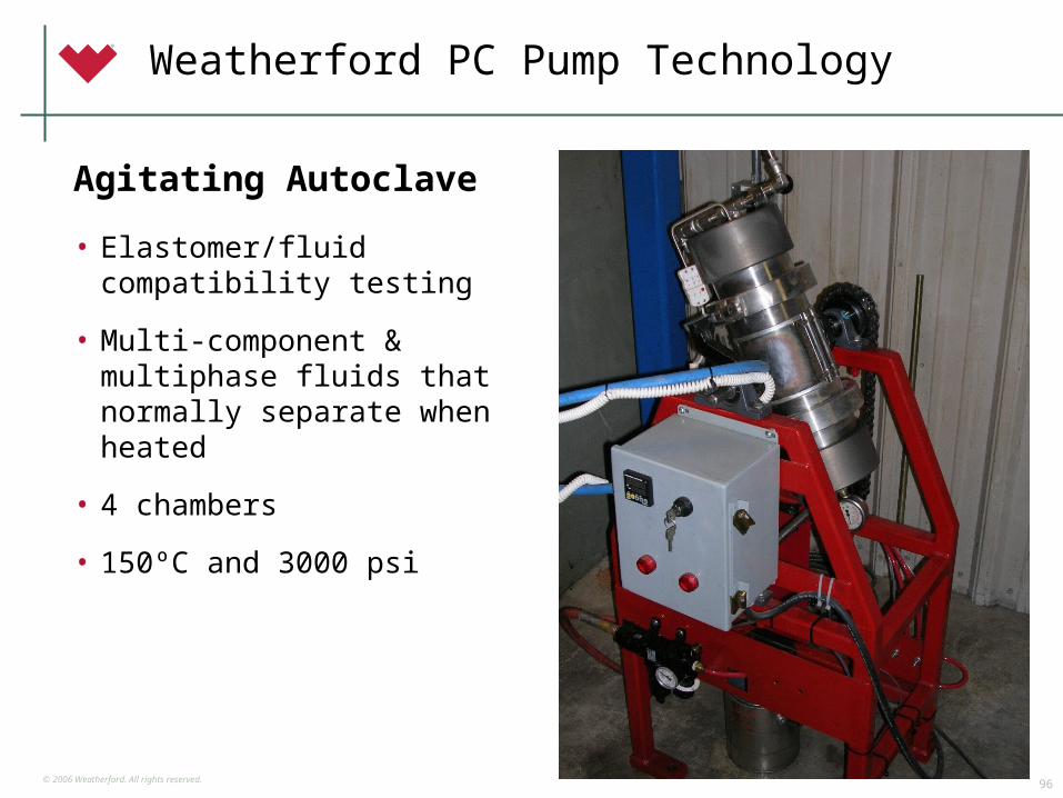
• Elastomer/fluid compatibility testing
• Multi-component & multiphase fluids that normally separate when heated
• 4 chambers
• 150ºC and 3000 psi
Agitating Autoclave
Weatherford PC Pump Technology
© 2006 Weatherford. All rights reserved.97
Weatherford PC Pump Technology
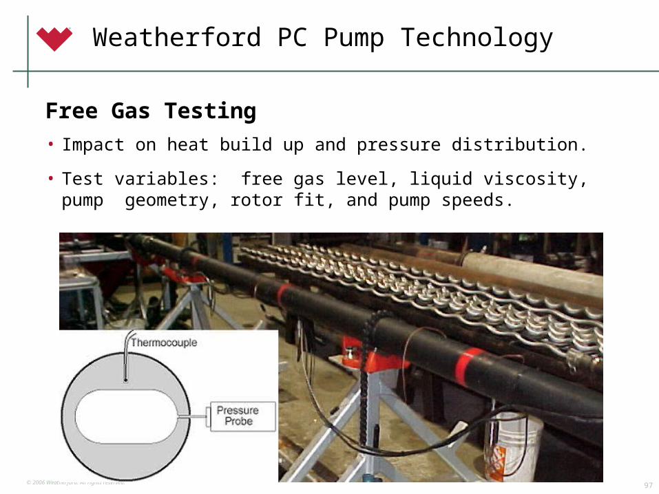
• Impact on heat build up and pressure distribution.
• Test variables: free gas level, liquid viscosity, pump geometry, rotor fit, and pump speeds.
Free Gas Testing

© 2006 Weatherford. All rights reserved.98
Technical Support
• Application Design
• Pump Optimization
• Problem Well Analysis
• Fluids Analysis
• Failure Analysis
• Customer services
• Logistics
• Training
Weatherford PC Pump Technology
© 2006 Weatherford. All rights reserved.99
PCP Strategic Partnering
© 2006 Weatherford. All rights reserved.100
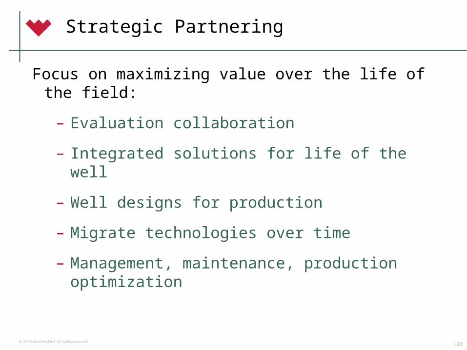
Strategic Partnering
Focus on maximizing value over the life of the field:
– Evaluation collaboration
– Integrated solutions for life of the well
– Well designs for production
– Migrate technologies over time
– Management, maintenance, production optimization

© 2006 Weatherford. All rights reserved.101
Strategic Partnering CASE STUDY
200
20.1
77 jo
bs/
wm
200
30.1
55 jo
bs/
wm
200
40.1
22 jo
bs/
wm
200
5 Y
TD
1.1
8 jo
bs/
wm
200
10.1
82 jo
bs/
wm
Service Jobs perWell Source: WHE-ALS-CIO
Start of WHE-ALS-CIOMarch 2001
Slope =-0.0015
Reduced service jobs per well.
200
2
200
3
200
4
200
5 Y
TD
$28
.8 M
$19
.2 M
200
1
Total Annual Service Job Cost Flat-line Comparison
Actual
Projected, based on servicejobs per well, 2001
Reduced total service cost.
© 2006 Weatherford. All rights reserved.102
Complementary Technologies
• All forms of Artificial Lift
• Formation evaluation
• Drilling & well construction
• Completion equipment & services
• Downhole sand control
• Surface sand management
• Production automation & optimization
• Intervention
• Pipe line heating
• Produced water treatment
© 2006 Weatherford. All rights reserved.103
Progressing Cavity Pump Products
© 2006 Weatherford. All rights reserved.104
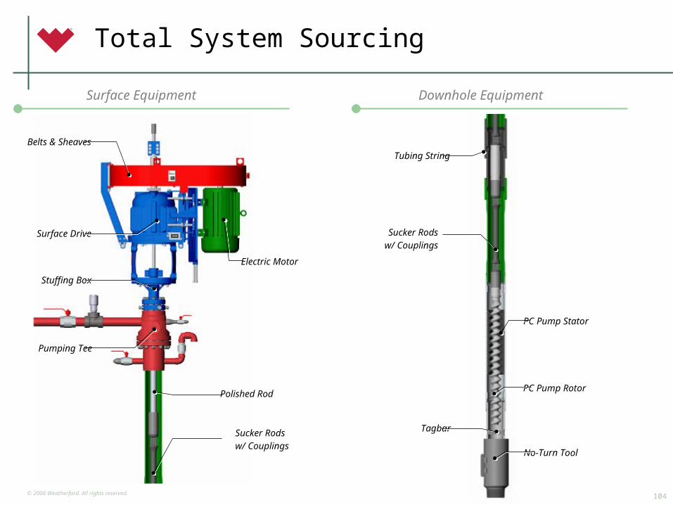
Total System Sourcing
Downhole Equipment
Belts & Sheaves
Surface Drive
Stuffing Box
Pumping Tee
Electric Motor
Polished Rod
Sucker Rodsw/ Couplings
Surface Equipment
PC Pump Stator
PC Pump Rotor
No-Turn Tool
Tubing String
Tagbar
Sucker Rodsw/ Couplings
© 2006 Weatherford. All rights reserved.105
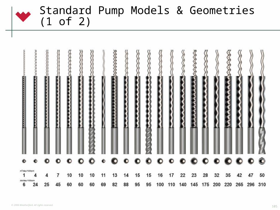
Standard Pump Models & Geometries (1 of 2)

© 2006 Weatherford. All rights reserved.106
Standard Pump Models & Geometries (2 of 2)
© 2006 Weatherford. All rights reserved.107
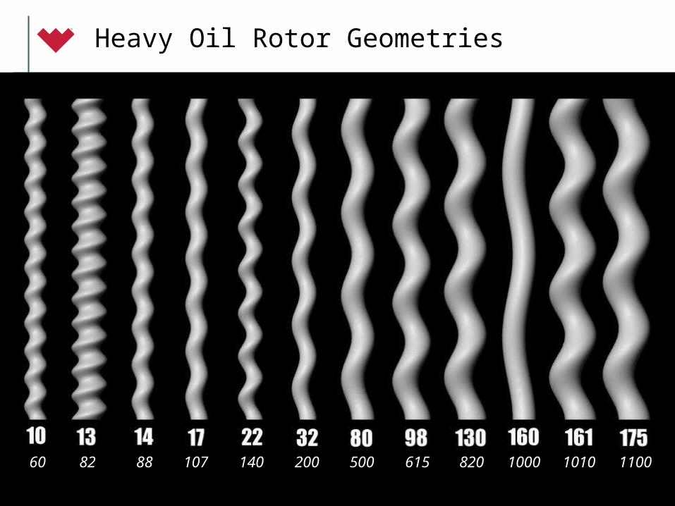
Heavy Oil Rotor Geometries
60 82 88 107 140 200 500 615 820 1000 1010 1100
© 2006 Weatherford. All rights reserved.108
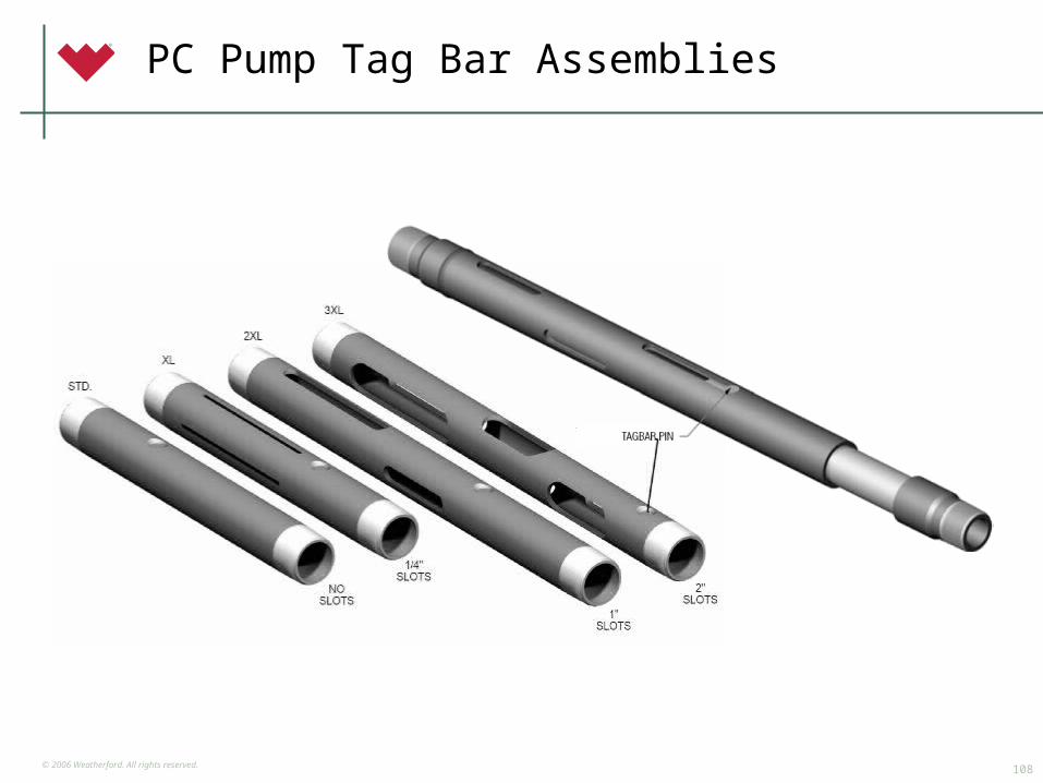
PC Pump Tag Bar Assemblies
© 2006 Weatherford. All rights reserved.109
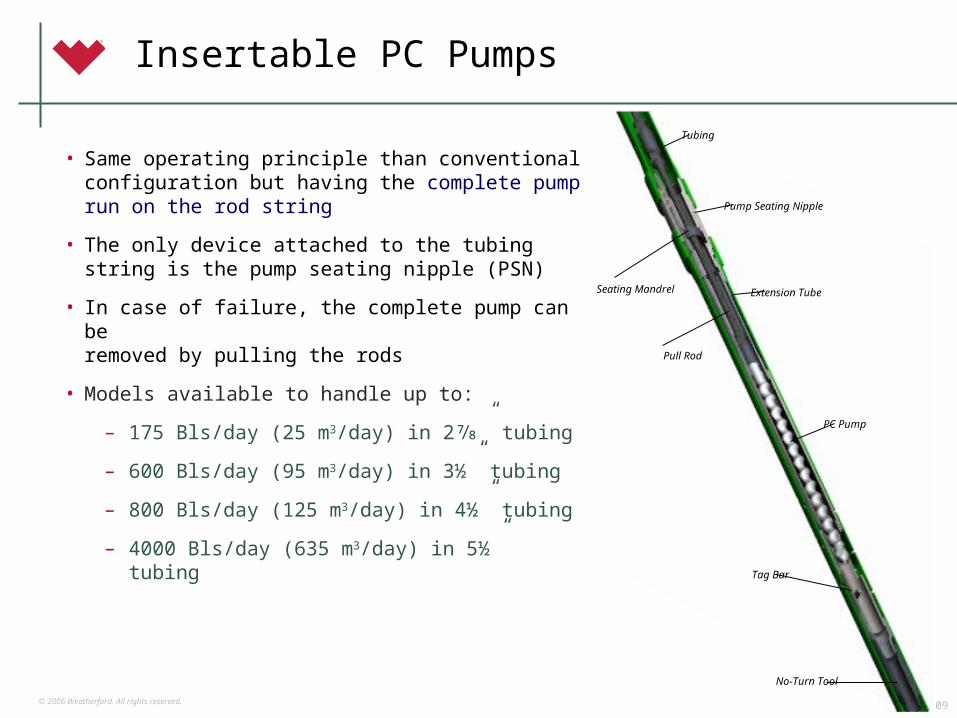
Insertable PC Pumps
Tubing
Pump Seating Nipple
Extension Tube
PC Pump
Seating Mandrel
Pull Rod
Tag Bar
No-Turn Tool
• Same operating principle than conventionalconfiguration but having the complete pumprun on the rod string
• The only device attached to the tubingstring is the pump seating nipple (PSN)
• In case of failure, the complete pump can beremoved by pulling the rods
• Models available to handle up to:
– 175 Bls/day (25 m3/day) in 2⅞” tubing
– 600 Bls/day (95 m3/day) in 3½” tubing
– 800 Bls/day (125 m3/day) in 4½” tubing
– 4000 Bls/day (635 m3/day) in 5½” tubing
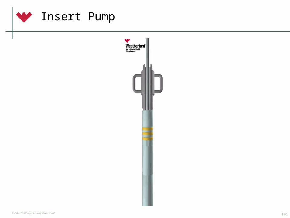
© 2006 Weatherford. All rights reserved.110
Insert Pump
© 2006 Weatherford. All rights reserved.111
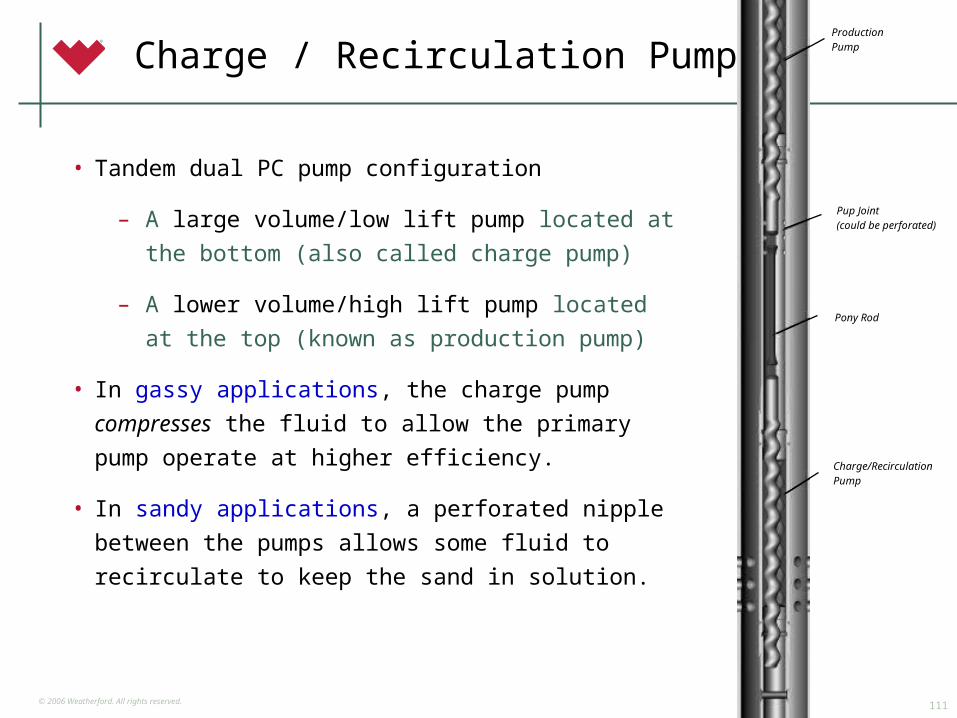
Charge / Recirculation PumpProductionPump
Pup Joint(could be perforated)
Pony Rod
Charge/RecirculationPump
• Tandem dual PC pump configuration
– A large volume/low lift pump located at the
bottom (also called charge pump)
– A lower volume/high lift pump located at the top
(known as production pump)
• In gassy applications, the charge pump compresses
the fluid to allow the primary pump operate at higher
efficiency.
• In sandy applications, a perforated nipple between the
pumps allows some fluid to recirculate to keep the
sand in solution.
© 2006 Weatherford. All rights reserved.112
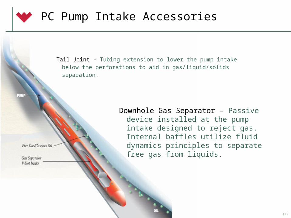
PC Pump Intake Accessories
Tail Joint – Tubing extension to lower the pump intake below the perforations to aid in gas/liquid/solids separation.
Downhole Gas Separator – Passive device installed at the pump intake designed to reject gas. Internal baffles utilize fluid dynamics principles to separate free gas from liquids.
© 2006 Weatherford. All rights reserved.113
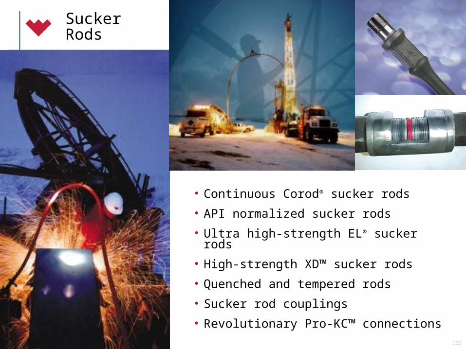
Sucker Rods
• Continuous Corod® sucker rods
• API normalized sucker rods
• Ultra high-strength EL® sucker rods
• High-strength XD™ sucker rods
• Quenched and tempered rods
• Sucker rod couplings
• Revolutionary Pro-KC™ connections
© 2006 Weatherford. All rights reserved.114
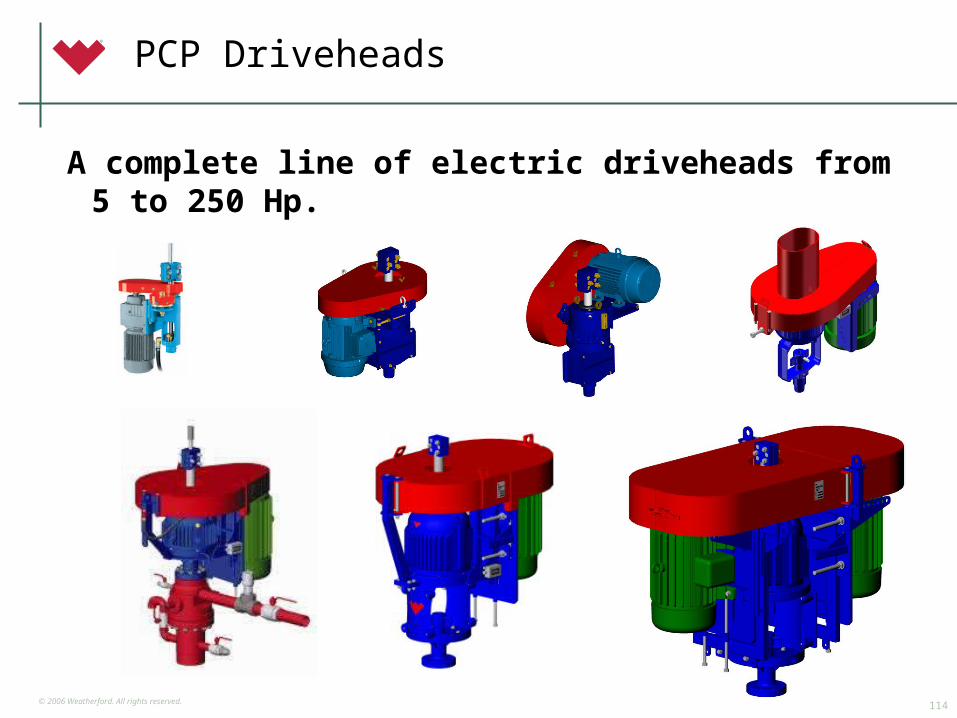
PCP Driveheads
A complete line of electric driveheads from 5 to 250 Hp.
© 2006 Weatherford. All rights reserved.115
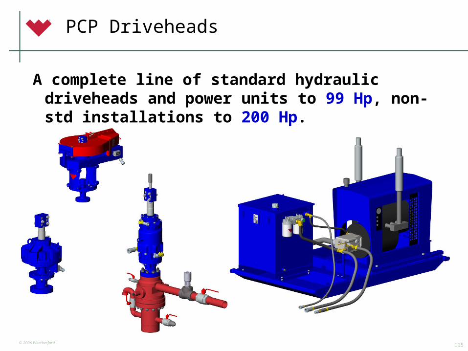
PCP Driveheads
A complete line of standard hydraulic driveheads and power units to 99 Hp, non-std installations to 200 Hp.
© 2006 Weatherford. All rights reserved.116
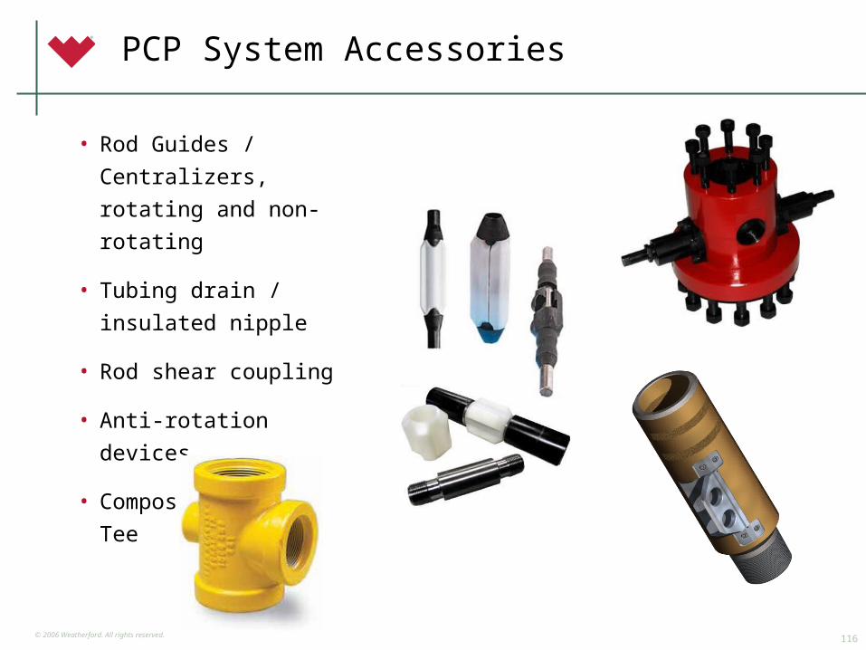
PCP System Accessories
• Rod Guides / Centralizers,
rotating and non-rotating
• Tubing drain / insulated
nipple
• Rod shear coupling
• Anti-rotation devices
• Composite Pumping Tee
© 2006 Weatherford. All rights reserved.117
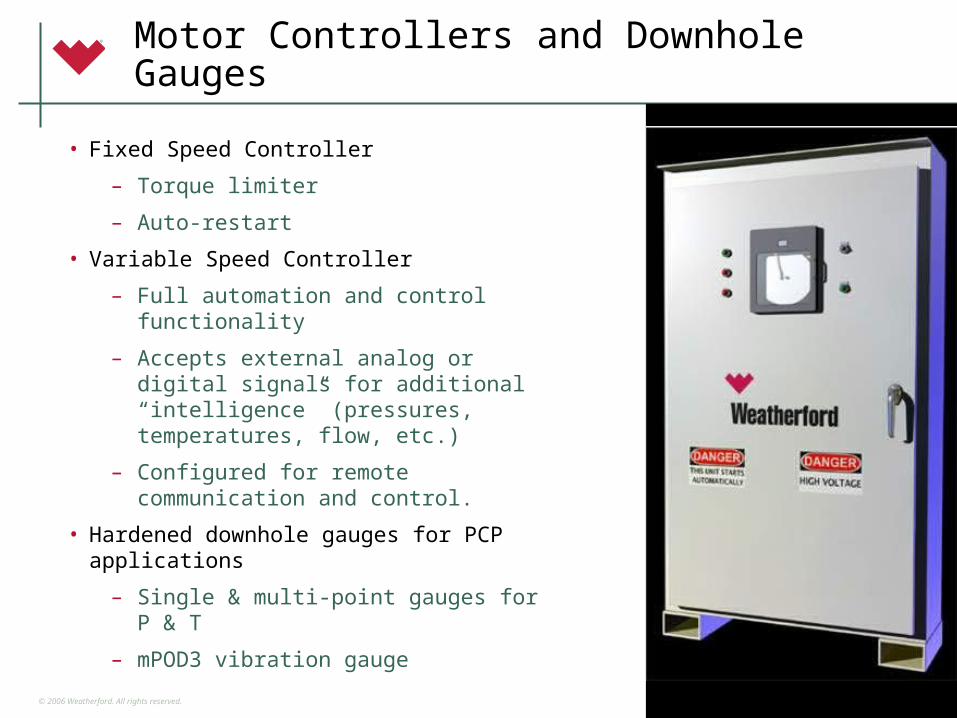
Motor Controllers and Downhole Gauges
• Fixed Speed Controller
– Torque limiter
– Auto-restart
• Variable Speed Controller
– Full automation and control functionality
– Accepts external analog or digital signals for additional “intelligence” (pressures, temperatures, flow, etc.)
– Configured for remote communication and control.
• Hardened downhole gauges for PCP applications
– Single & multi-point gauges for P & T
– mPOD3 vibration gauge

© 2006 Weatherford. All rights reserved.118
Weatherford Differentiation
Weatherford brand recognition and acceptance
Global service infrastructure
Engineering and technology
- Application design expertise
- Technical support including 3 elastomer labs
- Testing and verification of performance
Supply chain depth and breadth – Three PCP production facilities plus supply chain partners
Proven performance
Total system solutions: pumps, rods, drives, controls, telemetry, gauges, and accessories
Strategic partnering

© 2006 Weatherford. All rights reserved.119
© 2006 Weatherford. All rights reserved.120SPE ESP Workshop 2009 - Houston Texas
Surface Pumps Horizontal Pumping Systems (HPS)
© 2006 Weatherford. All rights reserved.121
Best solutions
• Dependable High “Uptime” percentage
• Minimal routing Maintenance
• Flexible - for changing operating conditions
• Low Capital Cost
• Low Maintenance Cost
• Low Whole Life Cost
© 2006 Weatherford. All rights reserved.122
Key advantages
• Increase production without drilling new wells
• Flooding: Water/CO2/Polymer
• Pressure maintenance
• Increase production from existing wells
• Low capital, operating and whole life cost
© 2006 Weatherford. All rights reserved.123
Applications
• Upstream Oil & Gas Applications:
– Produced Water Injection (Disposal, Waterflood, Pressure Maintenance)
– Power Fluid Pump (for downhole Jet/Hydraulic pump)
– Liquid CO2 for Transfer or Injection
– Crude Oil Transfer
– Boiler Feed for steam generators - SAGD
© 2006 Weatherford. All rights reserved.124
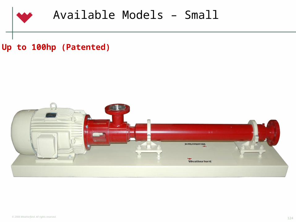
Available Models – Small
Up to 100hp (Patented)
© 2006 Weatherford. All rights reserved.125
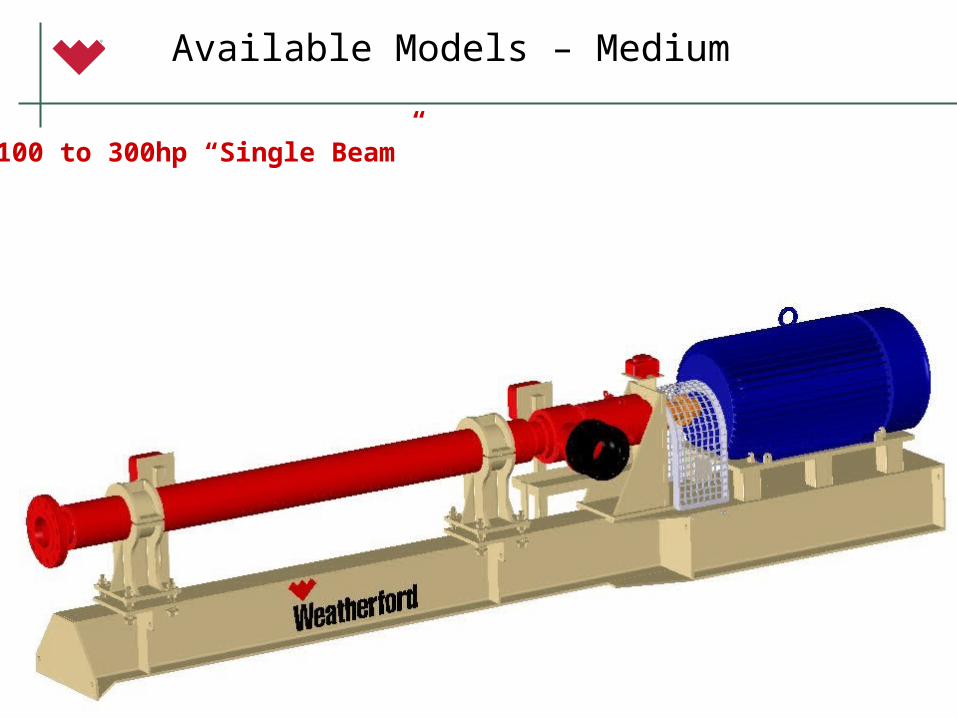
Available Models – Medium
100 to 300hp “Single Beam”
© 2006 Weatherford. All rights reserved.126
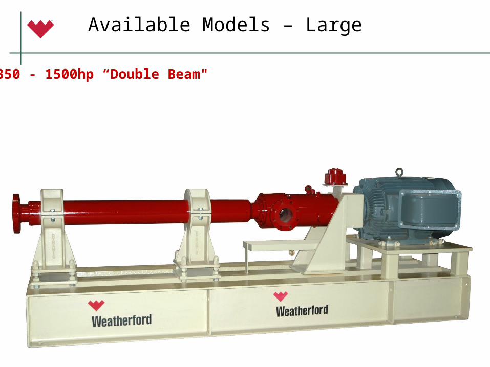
Available Models – Large
350 - 1500hp “Double Beam"
© 2006 Weatherford. All rights reserved.127
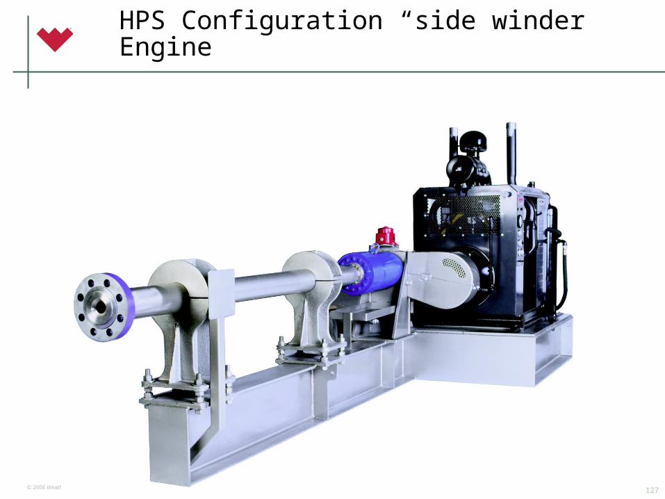
HPS Configuration “side winder” Engine
© 2006 Weatherford. All rights reserved.128
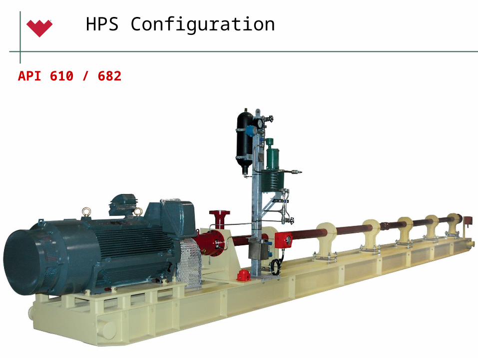
HPS Configuration
API 610 / 682
© 2006 Weatherford. All rights reserved.129
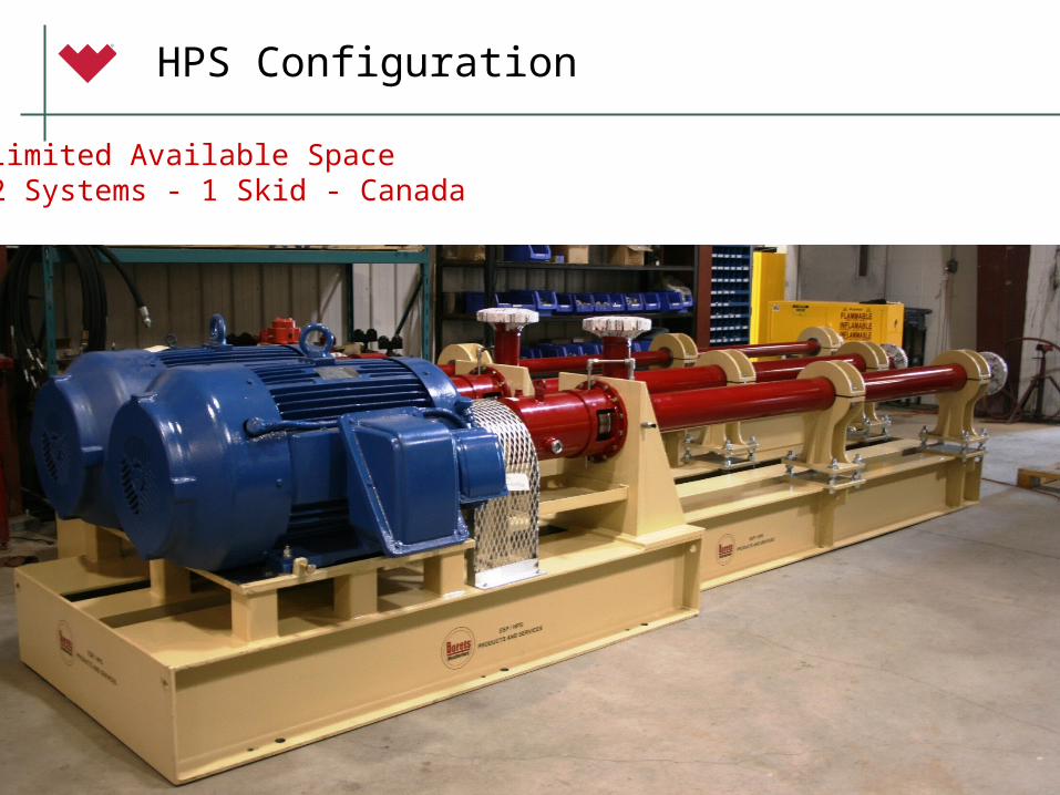
HPS Configuration
Limited Available Space2 Systems - 1 Skid - Canada
© 2006 Weatherford. All rights reserved.130
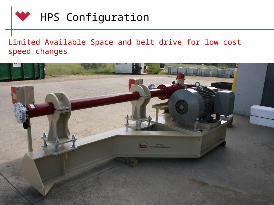
HPS Configuration
Limited Available Space and belt drive for low cost speed changes
© 2006 Weatherford. All rights reserved.131
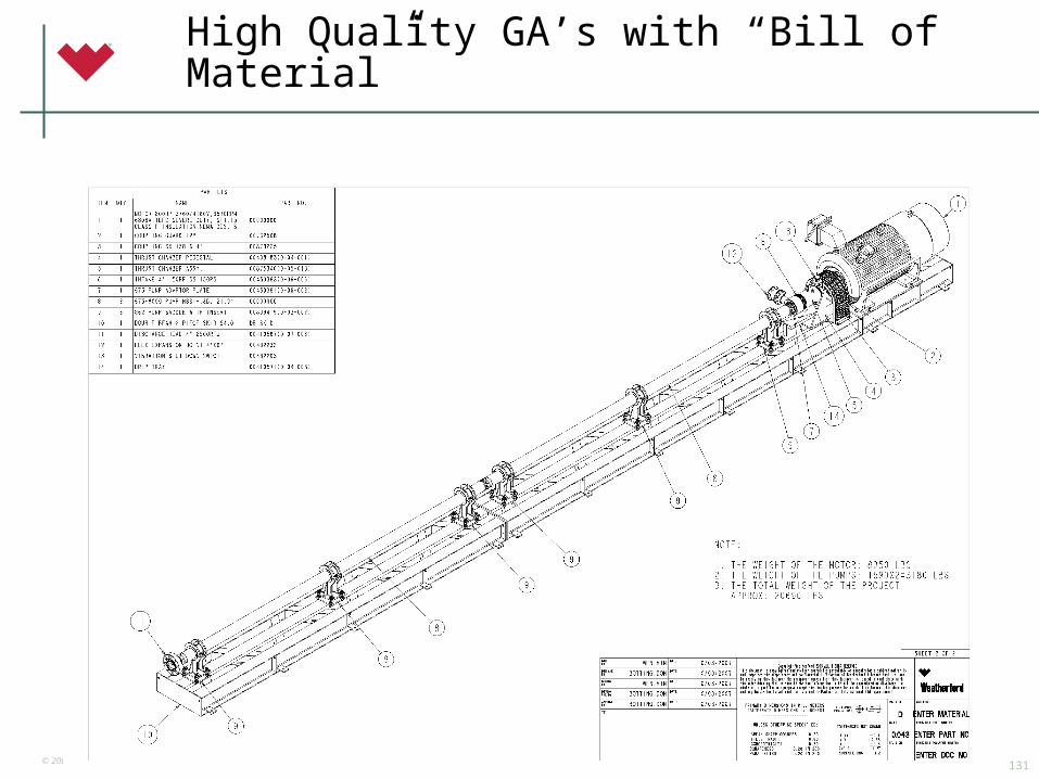
High Quality GA’s with “Bill of Material”
© 2006 Weatherford. All rights reserved.132
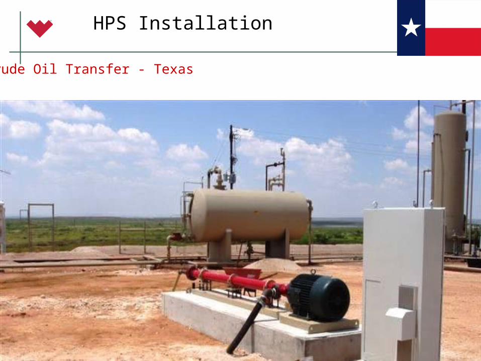
HPS Installation
Crude Oil Transfer - Texas
© 2006 Weatherford. All rights reserved.133
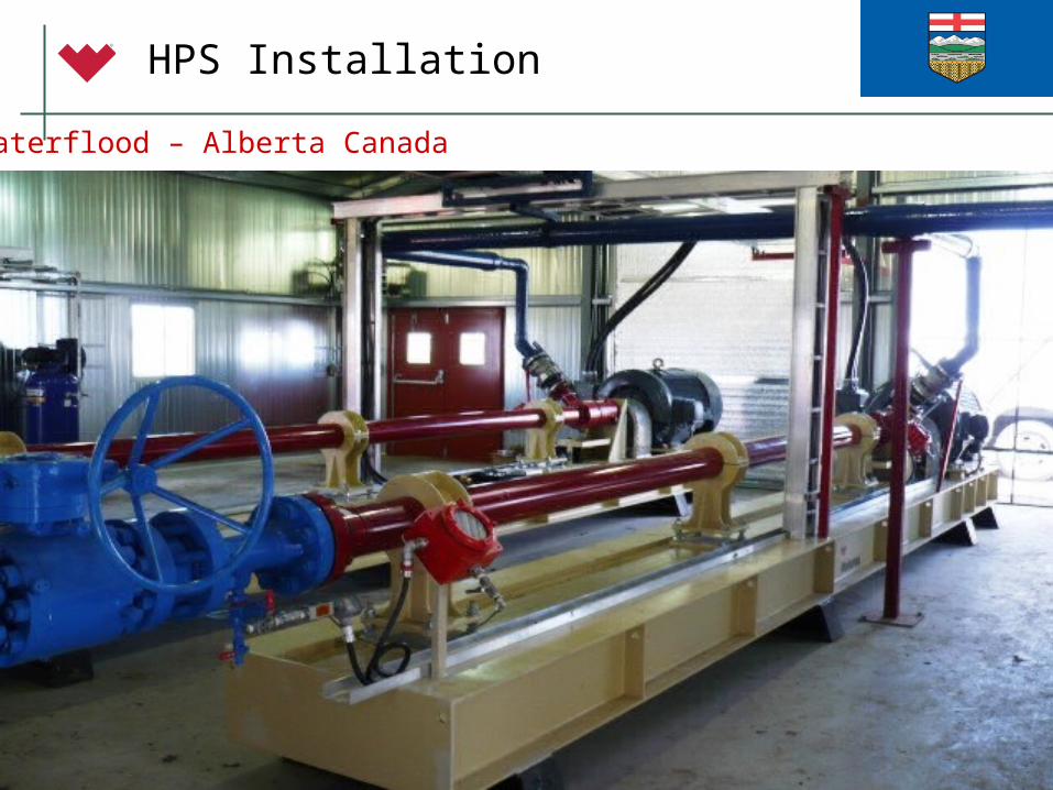
HPS Installation
Waterflood – Alberta Canada
© 2006 Weatherford. All rights reserved.134
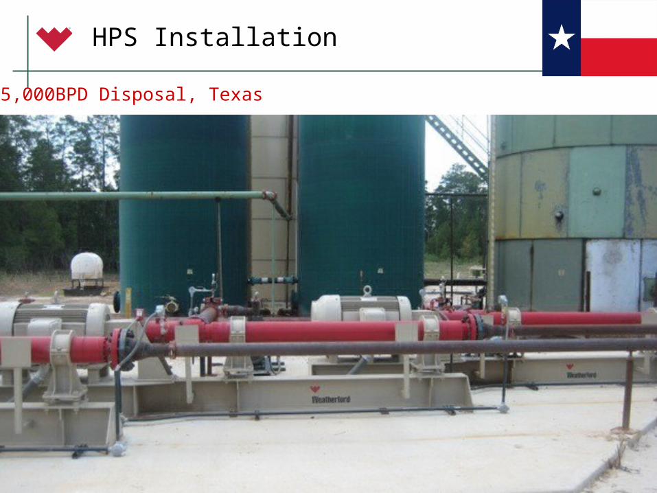
HPS Installation
75,000BPD Disposal, Texas
© 2006 Weatherford. All rights reserved.135
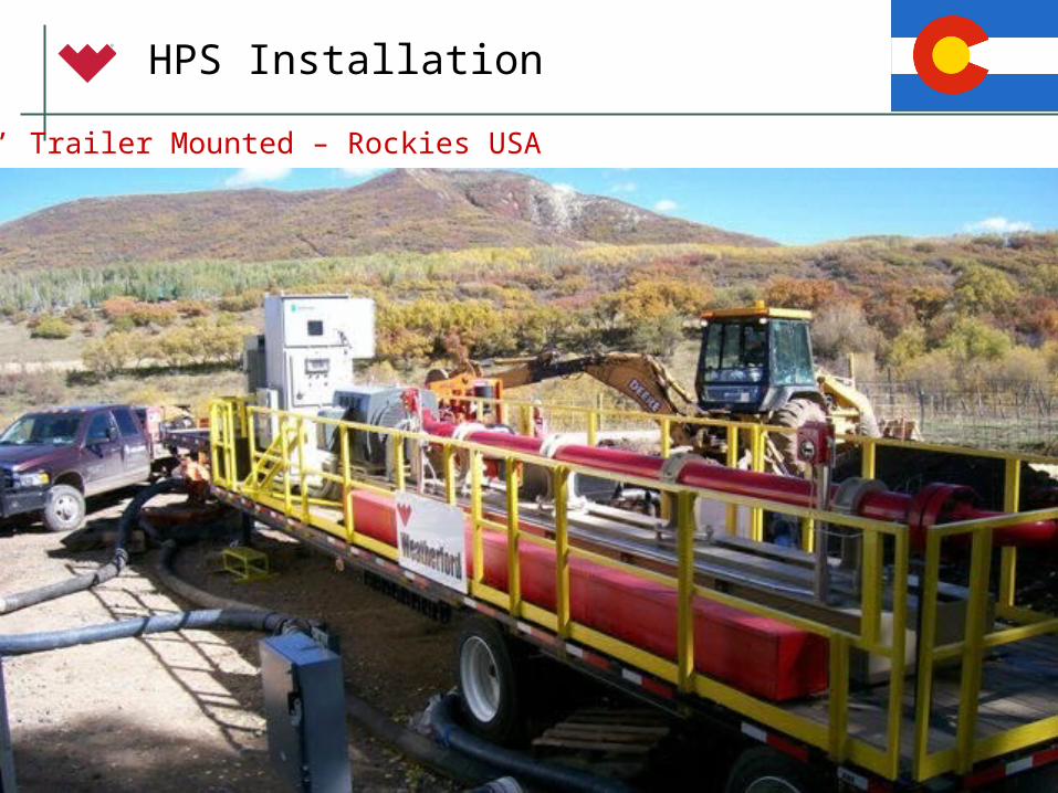
HPS Installation
53’ Trailer Mounted – Rockies USA
© 2006 Weatherford. All rights reserved.136
HPS Installation
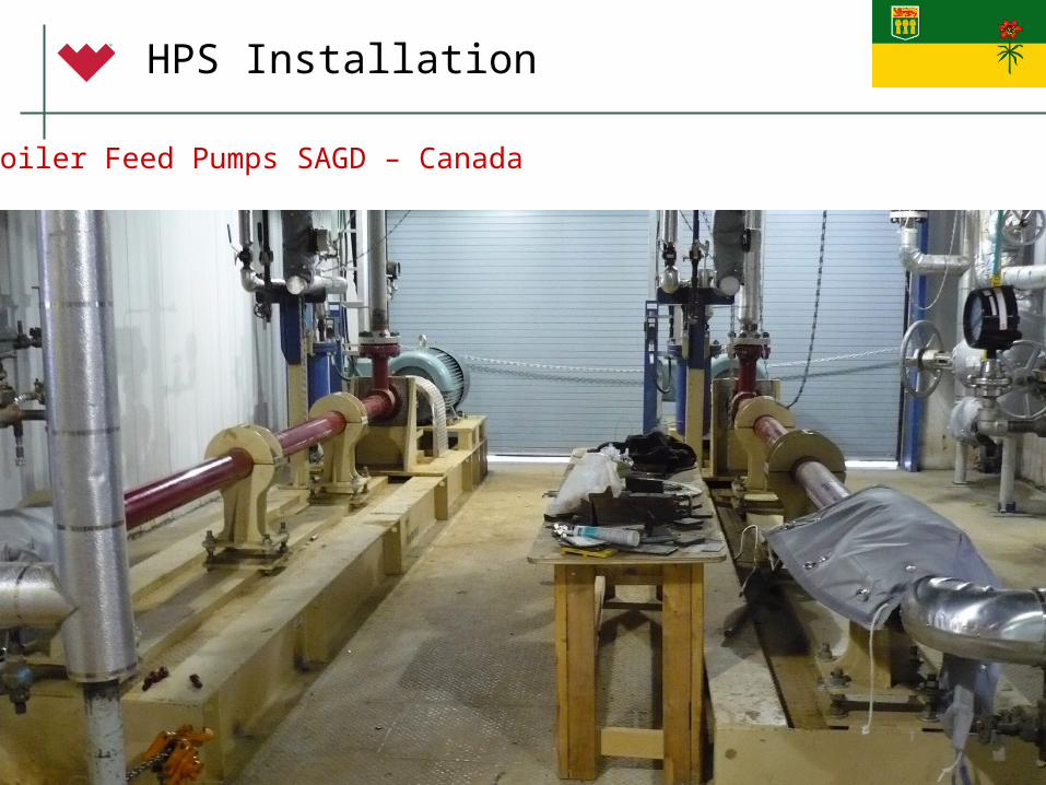
Boiler Feed Pumps SAGD – Canada
© 2006 Weatherford. All rights reserved.137
HPS Installation
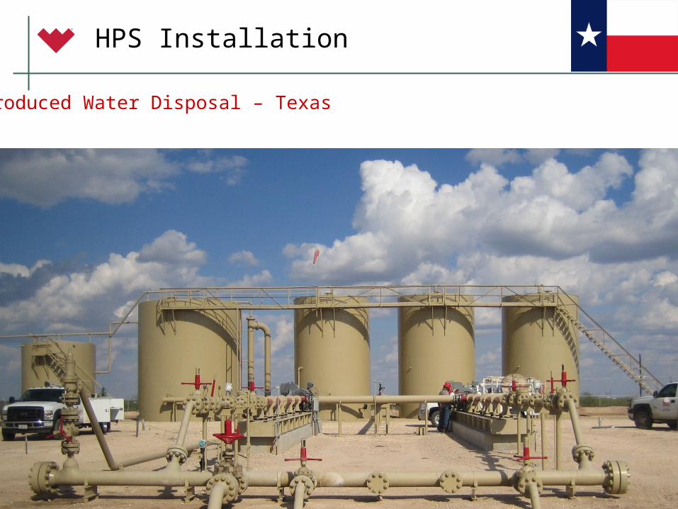
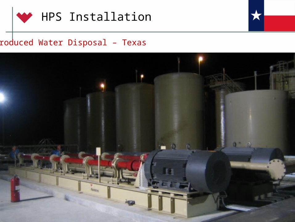
Produced Water Disposal – Texas
© 2006 Weatherford. All rights reserved.138
HPS Installation
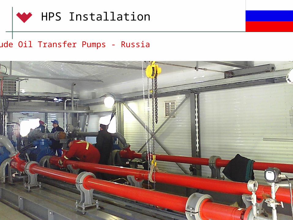
Crude Oil Transfer Pumps - Russia
© 2006 Weatherford. All rights reserved.139
HPS Installation
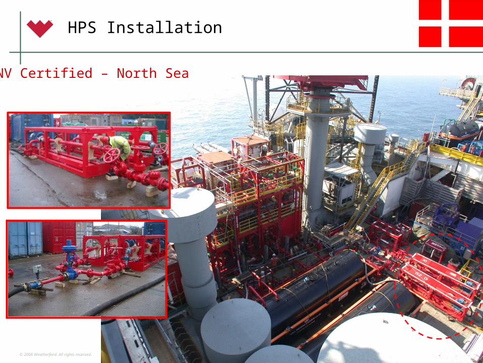
DNV Certified – North Sea
© 2006 Weatherford. All rights reserved.140
HPS Installation
Produced Water Disposal – Texas
© 2006 Weatherford. All rights reserved.141
HPS Installation
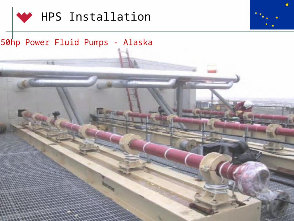
1250hp Power Fluid Pumps - Alaska
© 2006 Weatherford. All rights reserved.142
HPS Installation
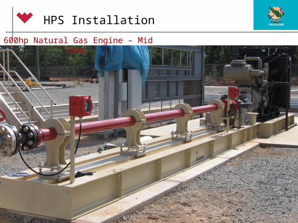
600hp Natural Gas Engine – Mid Cont.
© 2006 Weatherford. All rights reserved.143
HPS Installation
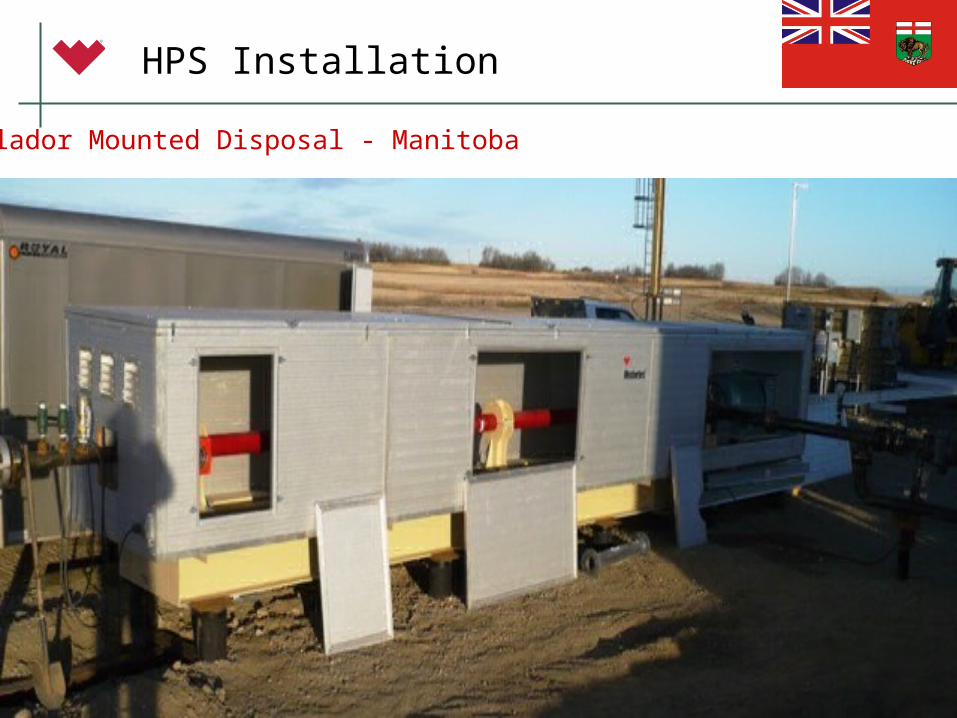
Utilador Mounted Disposal - Manitoba
© 2006 Weatherford. All rights reserved.144
HPS Installation
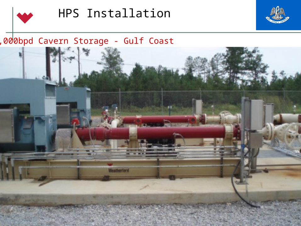
70,000bpd Cavern Storage - Gulf Coast
© 2006 Weatherford. All rights reserved.145
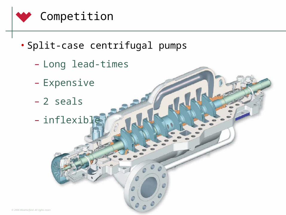
Competition
• Split-case centrifugal pumps
– Long lead-times
– Expensive
– 2 seals
– inflexible
© 2006 Weatherford. All rights reserved.146
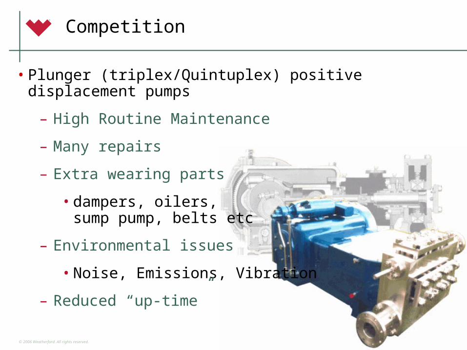
Competition
• Plunger (triplex/Quintuplex) positive displacement pumps
– High Routine Maintenance
– Many repairs
– Extra wearing parts
• dampers, oilers, sump pump, belts etc
– Environmental issues
• Noise, Emissions, Vibration
– Reduced “up-time”
© 2006 Weatherford. All rights reserved.147
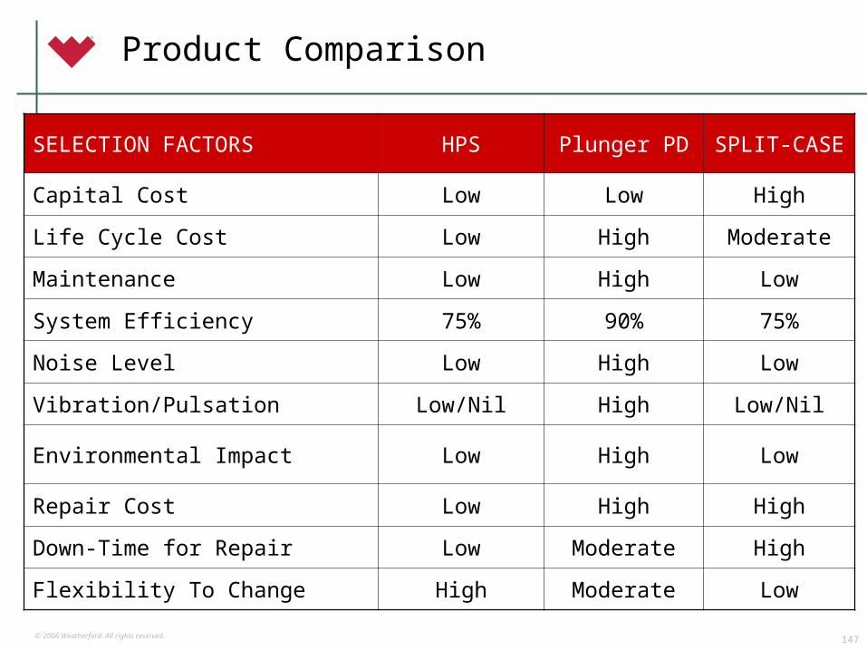
Product Comparison
SELECTION FACTORS HPS Plunger PD SPLIT-CASE
Capital Cost Low Low High
Life Cycle Cost Low High Moderate
Maintenance Low High Low
System Efficiency 75% 90% 75%
Noise Level Low High Low
Vibration/Pulsation Low/Nil High Low/Nil
Environmental Impact Low High Low
Repair Cost Low High High
Down-Time for Repair Low Moderate High
Flexibility To Change High Moderate Low

© 2006 Weatherford. All rights reserved.148
Summary of Benefits
• Short delivery lead times
• Competitive pricing
• Reliable for 24/7 operations
• Minimal routine maintenance
• Easily replaced components (pump, TC, seal)
• Maximum “up-time”
• Flexible – for changing operating conditions