Embed Size (px)
Citation preview
Analog Annunciator Unit
Product Guide
SACO 16 A3

Analog Annunciator Unit
Product Guide
SACO 16 A31MRS750405-MBG
Issued: Aprill 1999Status: Updated Version: C/20.03.2006Data subject to change without notice
3
Features Powerful, flexible and field-customizable 16-channel analog input signal annunciator unit
A full choice of 26 standardized field-selectable channel input signal types
Four alarm/trip levels per channel; two low set and two high set points
The last thirty events with time markings stored for local presentation
Bar graph, curve or numerical display of set and measured parameter values
Extensive data communication via the serial interface and the SPA bus
Parameter selection and adjustment from front panel or via serial interface
Sophisticated hardware and software self-supervision system for maximum opera-tional reliability under the most demanding environmental conditions
Powerful software support for parameter-ization of the relay, for reading measured and recorded values, events, etc., and for storing readings
Member of the SPACOM product family and ABBs Distribution Automation system
CE marking according to the EC directive for EMC
Application The analog annunciator unit is used in a vari-ety of applications requiring monitoring of analog quantities such as temperature, cur-rent, voltage, power, etc. in power plants, substations and industry. The equipment is also used in off-shore installations. For tem-perature measurement standard Pt or Ni sen-sors are used. For measuring electrical quantities measuring transducers with stan-dard mA or V outputs are employed.
The annunciator units can be used as indepen-dent stand-alone units, or they can be inte-grated via a fibre-optic bus to form complete supervision, event sequence reporting and data acquisition systems.
Analog Annunciator Unit
Product Guide
SACO 16 A31MRS750405-MBG
Design The channels of the analog annunciator unit measure voltage, current and resistance via sensors or transducers in the process. Further, contact signals can be wired to the input channels. The signal type can be separately set for each channel.
The channel inputs are galvanically separated from earth and from the digital part of the annunciator electronics, but the channels are galvanically interconnected. This arrange-ment facilitates the supervision and the indi-cation of earth faults in the transducers or the transducer wiring.
The alarm channel inputs accept the follow-ing signal levels: 05 mA, 15 mA, 020 mA and 420 mA, 01 V, 05 V, 15 V, 010 V and 210 V. The following standard sensors types can be used for tem-perature measurement: Pt 100, Pt 250, Pt 1000, Ni 100, Ni 120, Ni 250, Ni 1000. Further, any Pt or Ni signal within the range 651000 Ω, potentiometric signal within the range 0200 Ω, 0500 Ω, 01 kΩ, 02 kΩ, 02.5 kΩ, 010 kΩ can be used and scaled. For the resistance sensors two- or three-wire connection can be used.
In addition, the input channels can be acti-vated by a making or a breaking contact.
The values measured can be shown as numer-ical values, bar graphs or curves on the dot matrix display on the front panel. The same information can also be read by a superior system via the serial interface.
The content of the event sequence register can be read on the display. The total system can be configured by means of the push-but-tons and the display on the front panel, or via the serial interface.
When a measured signal exceeds or falls below the set start value of the channel a visual indication is obtained on the alarm
panel. At the same time the acoustic alarm output contact picks up and, if configured, a group alarm relay operates. The event thus generated is stored in the event register.
Any information generated in the annunciator unit can be read by a hierarchically superior system via the serial interface.
Data communicationThe relay is provided with a serial interface on the rear panel. By means of a bus connec-tion module type SPA-ZC 17/S or SPA-ZC 21/S the relay can be connected to the fibre-optic SPA bus. The bus connection module type SPA-ZC 21/S is powered from the host relay, whereas the bus connection module SPA-ZC 17/S is provided with a built-in power unit, which can be fed from an external secured power source. The relay communicates with higher-level data acquisi-tion and control systems over the SPA bus.
Self-supervisionThe annunciator incorporates a sophisticated self-supervision system which increases the availability of the device and the reliability of the system. The self-supervision system con-tinuously monitors the hardware and the soft-ware of the equipment. The system also supervises the operation of the auxiliary sup-ply module and the electronics voltages gen-erated by the module.
Auxiliary supply voltageThe auxiliary supply of the relay is obtained from an internal plug-in type power supply module. Two auxiliary power module ver-sions are available: type SPGU 240A1 for the supply voltage range 80265 V ac/dc and type SPGU 48B2 for the supply voltage range 1880 V dc. The power supply module forms the internal voltages required by the annunciator.
4
Analog Annunciator Unit
Product Guide
SACO 16 A31MRS750405-MBG
5
Technical data Table 1: Annunciator channelsNumber of channels per annunciator unit 16Selectable transducer signal types 05 mA, 15 mA, 020 mA, 420 mA
01 V, 05 V, 15 V, 010 V, 210 VPt 100, Pt 250, Pt 1000Ni 100, Ni 120, Ni 250, Ni 1000One selectable Pt or Ni signal within the range 651000 Ω, potentiometric signal within the range 0200 Ω, 0500 Ω, 01 kΩ, 02 kΩ, 02.5 kΩ, 010 kΩ,contact function
Scaling types linear or non-linearSignal filtering, selectable time basis for 090% step response
0.3 s, 1 s or 5 s
Set-point values per channel two HI and two LO set-points or one HI and one LO plus one rise time and one fall time set-point
Channel starting delay at set-point value transition 0255 sChannel resetting delay at set-point value resetting 0255 sDeadband setting range, on a per channel basis 0100 per milleMeasuring accuracy 0.5% of scale rangeTransducer supply 24 V dc ±10%, max. 320 mATransducer supervision, measuring mode Fully selectable upper and lower transducer signal
limit valuesTransducer circuit earth-fault supervision Integrated with a sensitivity of 510 kΩTransducer oscillation supervision Selectable 1255 events/s. Can even be set out of
functionReference channel function Any channel may be used as reference channel.
The reference value may also be the average value of the measurement value of channels 216
Reference value deviation set-point values Two selectable set-point values, one upper and one lower, separately given at 33% and 83% of the measuring range. Between these given set-point values the set-point values are interpolated and outside the given set-point values the set-point values are extLrapolated from the given set-point values
Recording of change in value to be measured Selectable setting value for size of change to be stored as an event in the event sequence register
Table 2: Realarm functionsPermanently groupable realarm output relays Six relays with one NO contact per relay. The
contacts may be given NC function by means of jumpers
Audible alarm output One relay with one NO contact(NC contact by jumper)
Self-supervision system output One relay with one NO contact(NC contact by jumper)
Relay contact rated current/max. breaking current 3 A/250 V ac or dc
Analog Annunciator Unit
Product Guide
SACO 16 A31MRS750405-MBG
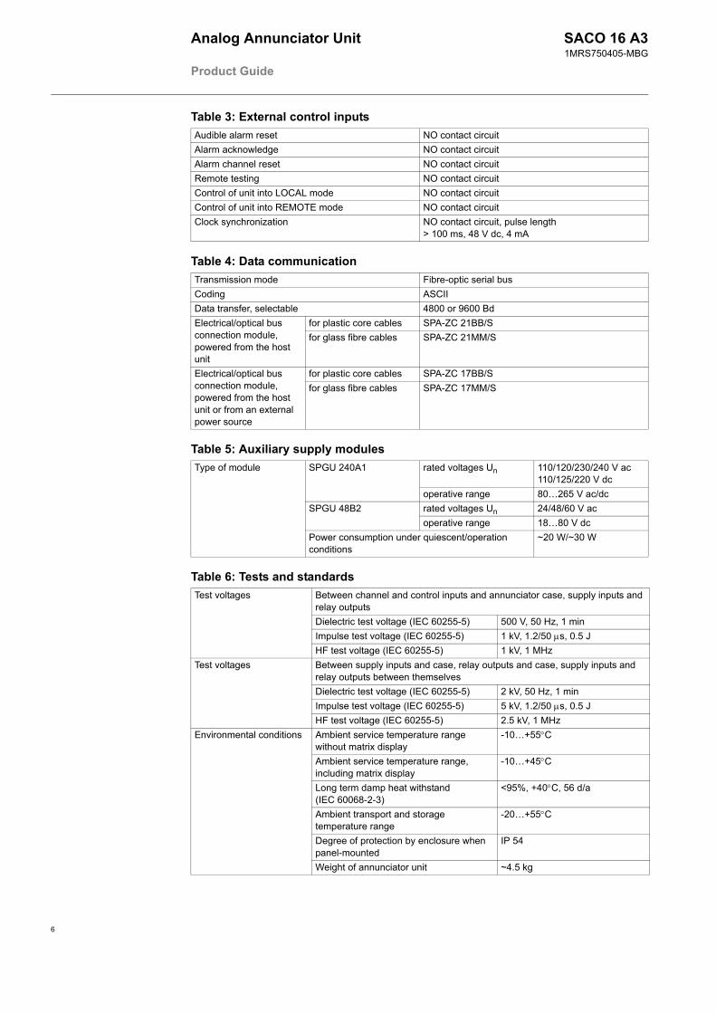
Table 3: External control inputsAudible alarm reset NO contact circuitAlarm acknowledge NO contact circuitAlarm channel reset NO contact circuitRemote testing NO contact circuitControl of unit into LOCAL mode NO contact circuitControl of unit into REMOTE mode NO contact circuitClock synchronization NO contact circuit, pulse length
> 100 ms, 48 V dc, 4 mA
Table 4: Data communicationTransmission mode Fibre-optic serial busCoding ASCIIData transfer, selectable 4800 or 9600 BdElectrical/optical bus connection module, powered from the host unit
for plastic core cables SPA-ZC 21BB/Sfor glass fibre cables SPA-ZC 21MM/S
Electrical/optical bus connection module, powered from the host unit or from an external power source
for plastic core cables SPA-ZC 17BB/Sfor glass fibre cables SPA-ZC 17MM/S
Table 5: Auxiliary supply modulesType of module SPGU 240A1 rated voltages Un 110/120/230/240 V ac
110/125/220 V dcoperative range 80265 V ac/dc
SPGU 48B2 rated voltages Un 24/48/60 V acoperative range 1880 V dc
Power consumption under quiescent/operation conditions
~20 W/~30 W
Table 6: Tests and standardsTest voltages Between channel and control inputs and annunciator case, supply inputs and
relay outputsDielectric test voltage (IEC 60255-5) 500 V, 50 Hz, 1 minImpulse test voltage (IEC 60255-5) 1 kV, 1.2/50 µs, 0.5 JHF test voltage (IEC 60255-5) 1 kV, 1 MHz
Test voltages Between supply inputs and case, relay outputs and case, supply inputs and relay outputs between themselvesDielectric test voltage (IEC 60255-5) 2 kV, 50 Hz, 1 minImpulse test voltage (IEC 60255-5) 5 kV, 1.2/50 µs, 0.5 JHF test voltage (IEC 60255-5) 2.5 kV, 1 MHz
Environmental conditions Ambient service temperature range without matrix display
-10+55°C
Ambient service temperature range, including matrix display
-10+45°C
Long term damp heat withstand (IEC 60068-2-3)
<95%, +40°C, 56 d/a
Ambient transport and storage temperature range
-20+55°C
Degree of protection by enclosure when panel-mounted
IP 54
Weight of annunciator unit ~4.5 kg
6
Analog Annunciator Unit
Product Guide
SACO 16 A31MRS750405-MBG
7
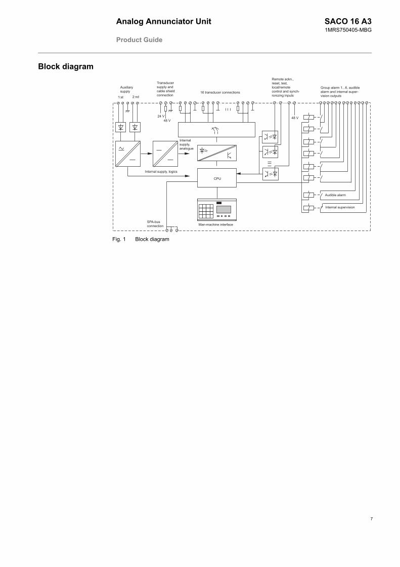
Block diagram
!"
#
$% %
&
$'
()* + ,
- $***'
Fig. 1 Block diagram
Analog Annunciator Unit
Product Guide
SACO 16 A31MRS750405-MBG
Mounting and dimensions
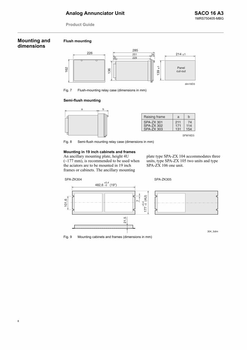
Flush mounting
Panelcut-out
214 ±1
dim16D3
139
±1
226
162
136
229
285251
3034
Fig. 7 Flush-mounting relay case (dimensions in mm)
Semi-flush mounting
Raising frame
SPA-ZX 301SPA-ZX 302SPA-ZX 303
211171131
74114154
a b
a b
Fig. 8 Semi-flush mounting relay case (dimensions in mm)
Mounting in 19 inch cabinets and framesAn ancillary mounting plate, height 4U (~177 mm), is recommended to be used when the aciators are to be mounted in 19 inch frames or cabinets. The ancillary mounting
plate type SPA-ZX 104 accommodates three units, type SPA-ZX 105 two units and type SPA-ZX 106 one unit.
482,6 –0 (19")
101,
6 7
177
–0 (
4U)
+0,4
+0,
4
21,5
304_5dim
SPA-ZK304 SPA-ZK305
Fig. 9 Mounting cabinets and frames (dimensions in mm)
8
Analog Annunciator Unit
Product Guide
SACO 16 A31MRS750405-MBG
9
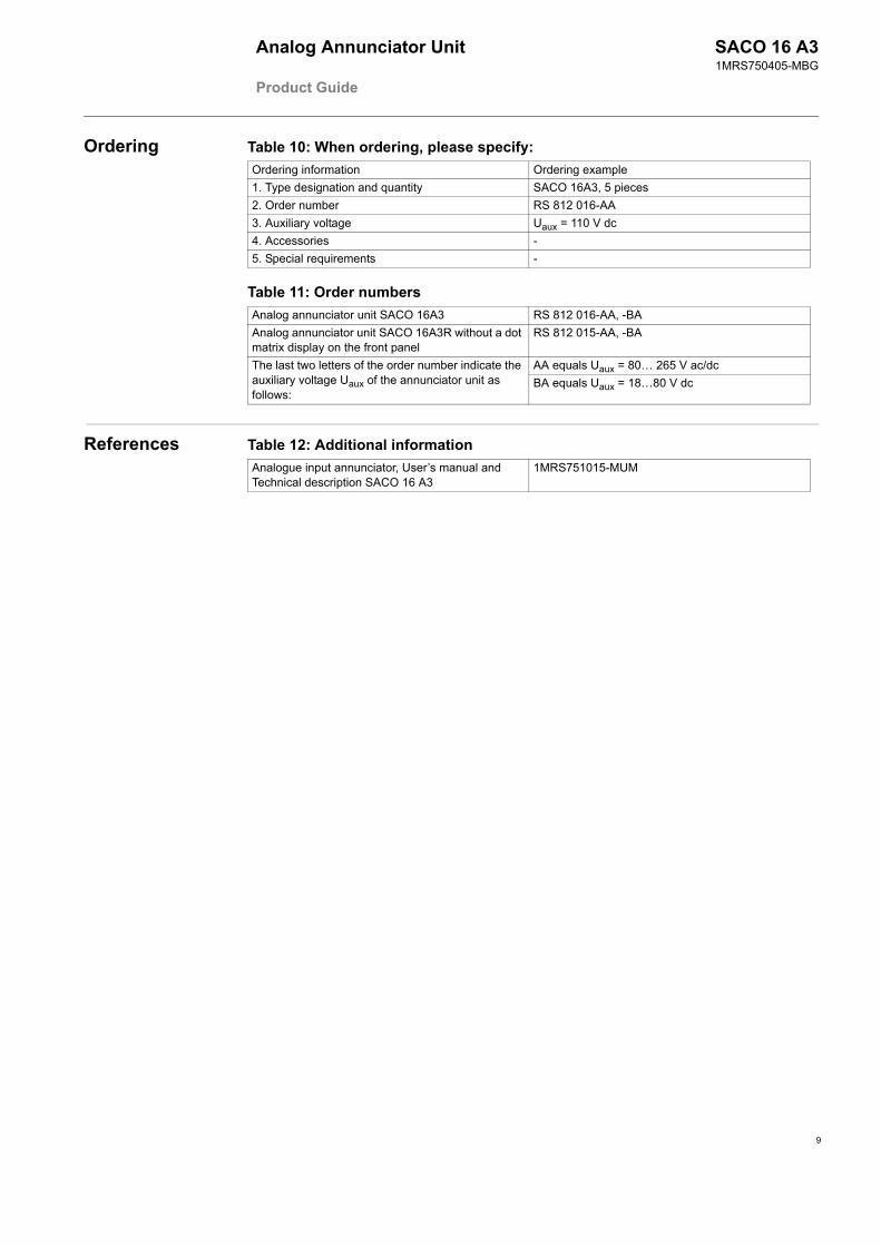
Ordering Table 10: When ordering, please specify:Ordering information Ordering example1. Type designation and quantity SACO 16A3, 5 pieces2. Order number RS 812 016-AA3. Auxiliary voltage Uaux = 110 V dc4. Accessories -5. Special requirements -
Table 11: Order numbersAnalog annunciator unit SACO 16A3 RS 812 016-AA, -BAAnalog annunciator unit SACO 16A3R without a dot matrix display on the front panel
RS 812 015-AA, -BA
The last two letters of the order number indicate the auxiliary voltage Uaux of the annunciator unit as follows:
AA equals Uaux = 80 265 V ac/dcBA equals Uaux = 1880 V dc
References Table 12: Additional informationAnalogue input annunciator, Users manual and Technical description SACO 16 A3
1MRS751015-MUM


ABB OyDistribution AutomationP.O. Box 699 FI-65101 Vaasa, FINLANDTel +358 10 22 11Fax +358 10 224 1094www.abb.com/substationautomation