Embed Size (px)
Citation preview
01.2004 V1.0 / 401 RE
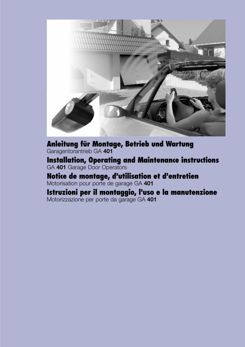
Anleitung für Montage, Betrieb und Wartung Garagentorantrieb GA 401
Installation, Operating and Maintenance instructions GA 401 Garage Door Operators
Notice de montage, d'utilisation et d'entretien Motorisation pour porte de garage GA 401
Istruzioni per il montaggio, l'uso e la manutenzione Motorizzazione per porte da garage GA 401
01.2004 V1.0 / 401 RE2
Ø 10 mm
Ø 5 mm
10 mm
13 mm
B
4 mm
3
2
A
CB FA D E
Deutsch................................................................................. 3English .................................................................................. 6Français ................................................................................ 9Italiano ................................................................................ 12
D E U T S C H
INHALTSVERZEICHNIS SEITE
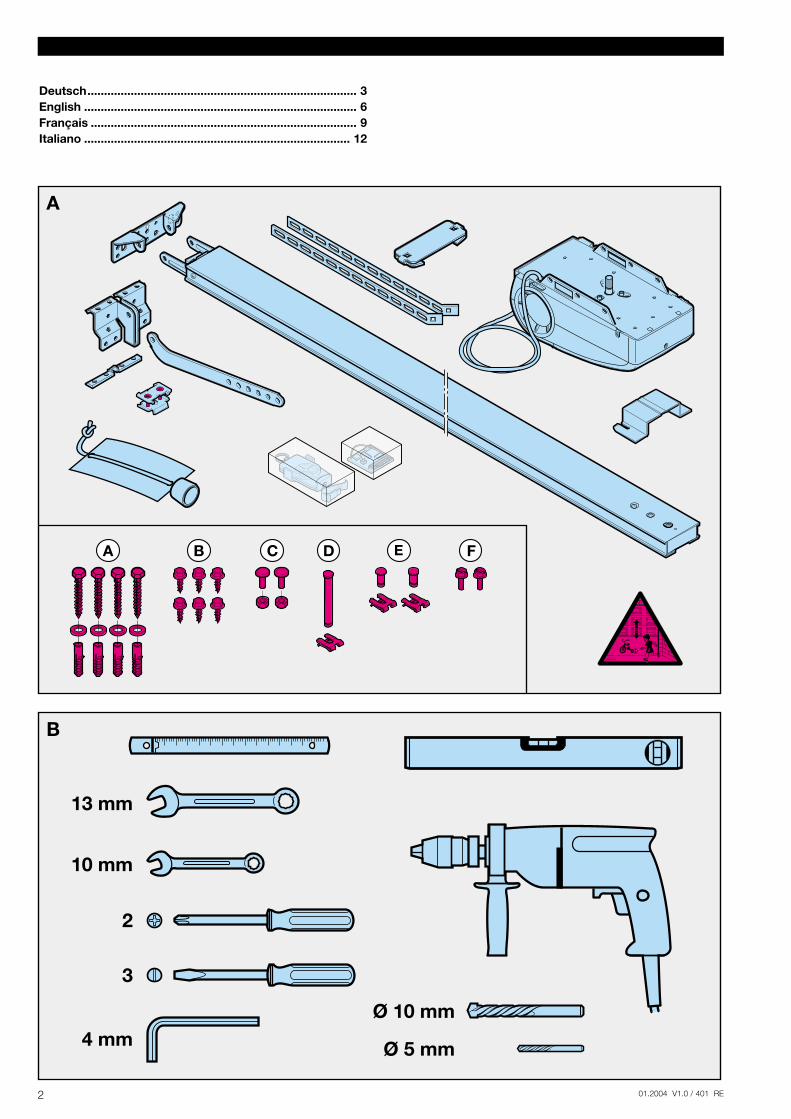
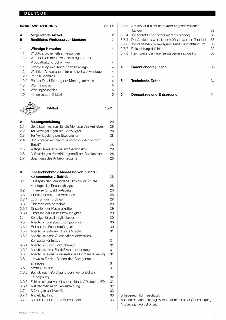
A Mitgelieferte Artikel 2B Benötigtes Werkzeug zur Montage 2
1 Wichtige Hinweise 41.1 Wichtige Sicherheitsanweisungen 41.1.1 Wir sind von der Gewährleistung und der
Produkthaftung befreit, wenn ... 41.1.2 Überprüfung des Tores / der Toranlage 41.2 Wichtige Anweisungen für eine sichere Montage 41.2.1 Vor der Montage 41.2.2 Bei der Durchführung der Montagearbeiten 41.3 Warnhinweise 51.4 Wartungshinweise 51.5 Hinweise zum Bildteil 5
Bildteil 15-27
2 Montageanleitung 282.1 Benötigter Freiraum für die Montage des Antriebes 282.2 Tor-Verriegelungen am Schwingtor 282.3 Tor-Verriegelung am Sectionaltor 282.4 Schwingtore mit einem kunstschmiedeeisernen
Torgriff 282.5 Mittiger Torverschluss am Sectionaltor 282.6 Außermittiges Verstärkungsprofil am Sectionaltor 282.7 Spannung des Antriebmediums 28
3 Inbetriebnahme / Anschluss von Zusatz-komponenten / Betrieb 28
3.1 Festlegen der Tor-Endlage "Tor-Zu" durch die Montage des Endanschlages 28
3.2 Hinweise für Elektro-Arbeiten 283.3 Inbetriebnahme des Antriebes 283.3.1 Löschen der Tordaten 283.3.2 Einlernen des Antriebes 293.3.3 Einstellen der Maximalkräfte 293.3.4 Einstellen der Laufgeschwindigkeit 293.4 Sonstige Einstellmöglichkeiten 303.5 Anschluss von Zusatzkomponenten 303.5.1 Einbau des Funkempfängers 303.5.2 Anschluss externer "Impuls"-Taster 313.5.3 Anschluss eines Ausschalters oder eines
Schlupftürkontaktes 313.5.4 Anschluss einer Lichtschranke 313.5.5 Anschluss einer Schließkantensicherung 313.5.6 Anschluss eines Zusatzrelais zur Lichtansteuerung 313.6 Hinweise für den Betrieb des Garagentor-
antriebes 313.6.1 Normal-Betrieb 313.6.2 Betrieb nach Betätigung der mechanischen
Entriegelung 323.6.3 Fehlermeldung Antriebsbeleuchtung / Diagose-LED 323.6.4 Maßnahmen nach Fehlermeldung 323.7 Störungen und Abhilfe 333.7.1 Antrieb läuft nicht 333.7.2 Antrieb läuft nicht mit Handsender 33
3.7.3 Antrieb läuft nicht mit extern angeschlossenen Tastern 33
3.7.4 Tor schließt oder öffnet nicht vollständig 333.7.5 Der Antrieb reagiert, jedoch öffnet sich das Tor nicht 333.7.6 Tor kehrt bei Zu-Bewegung seine Laufrichtung um 333.7.7 Beleuchtung defekt 333.7.8 Reichweite der Funkfernsteuerung zu gering 33
4 Garantiebedingungen 33
5 Technische Daten 34
6 Demontage und Entsorgung 34
Urheberrechtlich geschützt. Nachdruck, auch auszugsweise, nur mit unserer Genehmigung. Änderungen vorbehalten.
301.2004 V1.0 / 401 RE
D E U T S C H
Sehr geehrter Kunde,
wir bedanken uns, dass Sie sich für ein Qualitäts-Produkt ausunserem Hause entschieden haben. Bitte bewahren Sie dieseAnleitung sorgfältig auf!
Beachten Sie bitte die nachfolgenden Hinweise, sie geben Ihnenwichtige Informationen für den Einbau und die Bedienung desGaragentorantriebes, damit Sie über viele Jahre Freude an diesemProdukt haben.
1 Wichtige Hinweise
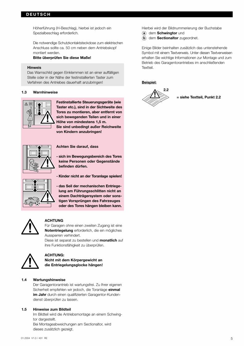
ACHTUNGEine falsche Montage bzw. eine falscheHandhabung des Antriebes kann zu ernst-haften Verletzungen führen. Befolgen Siedaher bitte alle Anweisungen, die in dieserAnleitung enthalten sind!
1.1 Wichtige SicherheitsanweisungenDer Garagentorantrieb ist ausschließlich für den Betriebvon federausgeglichenen Schwing- und Sectionaltoren vorgesehen.
1.1.1 Wir sind von der Gewährleistung und der Produkt-haftung befreit, wenn ohne unsere vorherige Zustim-mung eigene bauliche Veränderungen vorgenommen oderunsachgemäße Installationen gegen unsere vorgegebenenMontagerichtlinien ausgeführt bzw. veranlasst werden.Weiterhin übernehmen wir keine Verantwortung für den versehentlichen oder unachtsamen Betrieb des Antriebesund des Zubehörs sowie für die unsachgemäße Wartungdes Tores und dessen Gewichtsausgleich.Batterien und Glühlampen sind ebenfalls von den Gewähr-leistungsansprüchen ausgenommen.
1.1.2 Überprüfung des Tores / der ToranlageDie Konstruktion des Antriebes ist nicht für den Betrieb schwerer Tore, das heißt Tore, die nicht mehr oder nur schwer von Hand geöffnet oder geschlossen werden können, ausgelegt. Aus diesem Grund ist es notwendig,vor der Antriebsmontage das Tor zu überprüfen undsicherzustellen, dass es auch von Hand leicht zubedienen ist.
Hierzu heben Sie das Tor ca. einen Meter an und lassenes los. Das Tor sollte in dieser Stellung stehen bleiben und sich weder nach unten noch nach oben bewegen.Bewegt sich das Tor doch in eine der beiden Richtungen,so besteht die Gefahr, dass die Ausgleichsfedern nicht richtig eingestellt oder defekt sind. In diesem Fall ist mit einer erhöhten Abnutzung und Fehlfunktionen der Toran-lage zu rechnen.
ACHTUNG: Lebensgefahr!Versuchen Sie nicht, die Ausgleichsfedern fürden Gewichtsausgleich des Tores oder derenHalterungen selbst auszuwechseln, nachzustellen,zu reparieren oder zu versetzen. Sie stehen unter
großer Spannung und können ernsthafteVerletzungen verursachen.
Kontrollieren Sie außerdem die gesamte Toranlage(Gelenke, Lager des Tores, Seile, Federn undBefestigungsteile) auf Verschleiß und eventuelleBeschädigungen. Prüfen Sie, ob Rost, Korrosionoder Risse vorhanden sind. Die Toranlage ist nichtzu benutzen, wenn Reparatur- oder Einstellarbeitendurchgeführt werden müssen, denn ein Fehler inder Toranlage oder ein falsch ausgerichtetes Torkann ebenfalls zu schweren Verletzungen führen.
HinweisBevor Sie den Antrieb installieren, lassen Sie zu Ihrer eigenen Sicherheit Arbeiten an den Ausgleichsfedern desTores und falls erforderlich, Wartungs- und Reparaturarbeitennur durch einen qualifizierten Garagentor-Kundendienst ausführen!
1.2 Wichtige Anweisungen für eine sichere MontageDer Weiterverarbeiter hat darauf zu achten, dass dienationalen Vorschriften für den Betrieb von elektrischen Geräten eingehalten werden.
1.2.1 Vor der Montage des Garagentorantriebes ist zu über-prüfen, ob sich das Tor mechanisch in einem guten Zu-stand und im Gleichgewicht befindet. Weiterhin ist zu prüfen, ob sich das Tor richtig öffnen und schließen lässt(siehe Kapitel 1.1.2).Außerdem sind die mechanischen Verriegelungen des Tores, die nicht für eine Betätigung mit einem Garagentor-antrieb benötigt werden, außer Betrieb zu setzen. Hierzuzählen insbesondere die Verriegelungsmechanismen des Torschlosses (siehe Kapitel 2.2 bis 2.3).
Der Garagentorantrieb ist für einen Betrieb in trockenen Räumen konstruiert und darf daher nicht im Freien mon-tiert werden. Die Garagendecke muss so ausgelegt sein,dass eine sichere Befestigung des Antriebes gewährleistetist. Bei zu hohen oder zu leichten Decken muss der An-trieb an zusätzlichen Streben befestigt werden.
1.2.2 Bei der Durchführung der Montagearbeiten sind diegeltenden Vorschriften zur Arbeitssicherheit zu befolgen.
ACHTUNGBei Bohrarbeiten ist der Antrieb abzudecken,weil Bohrstaub und Späne zu Funktions-störungen führen können.
Der Freiraum zwischen dem höchsten Punkt des Tores und der Decke muss (auch beim Öffnen des Tores) mind.30 mm betragen (siehe Bild 1.1a / 1.1b). Bei einem geringe-ren Freiraum kann, sofern genügend Platz vorhanden ist, der Antrieb auch hinter dem geöffneten Tor montiert wer-den. In diesen Fällen muss ein verlängerter Tormitnehmereingesetzt werden, welcher separat zu bestellen ist. Der Garagentorantrieb kann max. 50 cm außermittig angeord-net werden. Ausgenommen sind Sectionaltore mit einer
4 01.2004 V1.0 / 401 RE
D E U T S C H
Höherführung (H-Beschlag), hierbei ist jedoch ein Spezialbeschlag erforderlich.
Die notwendige Schutzkontaktsteckdose zum elektrischenAnschluss sollte ca. 50 cm neben dem Antriebskopf montiert werden. Bitte überprüfen Sie diese Maße!
HinweisDas Warnschild gegen Einklemmen ist an einer auffälligenStelle oder in der Nähe der festinstallierten Taster zumVerfahren des Antriebes dauerhaft anzubringen!
1.3 Warnhinweise
Festinstallierte Steuerungsgeräte (wieTaster etc.), sind in der Sichtweite desTores zu montieren, aber entfernt vonsich bewegenden Teilen und in einerHöhe von mindestens 1,5 m.Sie sind unbedingt außer Reichweitevon Kindern anzubringen!
Achten Sie darauf, dass
- sich im Bewegungsbereich des Toreskeine Personen oder Gegenstände befinden dürfen.
- Kinder nicht an der Toranlage spielen!
- das Seil der mechanischen Entriege-lung am Führungsschlitten nicht an einem Dachträgersystem oder sons-tigen Vorsprüngen des Fahrzeuges oder des Tores hängen bleiben kann.
ACHTUNGFür Garagen ohne einen zweiten Zugang ist eineNotentriegelung erforderlich, die ein möglichesAussperren verhindert.Diese ist separat zu bestellen und monatlich aufihre Funktionsfähigkeit zu überprüfen.
ACHTUNG: Nicht mit dem Körpergewicht an die Entriegelungsglocke hängen!
1.4 WartungshinweiseDer Garagentorantrieb ist wartungsfrei. Zu Ihrer eigenen Sicherheit empfehlen wir jedoch, die Toranlage einmal im Jahr durch einen qualifizierten Garagentor-Kunden-dienst überprüfen zu lassen.
1.5 Hinweise zum BildteilIm Bildteil wird die Antriebsmontage an einem Schwing-tor dargestellt.Bei Montageabweichungen am Sectionaltor, wird dieses zusätzlich gezeigt.
Hierbei wird der Bildnummerierung der Buchstabe
Oa dem Schwingtor und
Ob dem Sectionaltor zugeordnet.
Einige Bilder beinhalten zusätzlich das untenstehende Symbol mit einem Textverweis. Unter diesen Textverweisenerhalten Sie wichtige Informationen zur Montage und zumBetrieb des Garagentorantriebes im anschließenden Textteil.
Beispiel:
= siehe Textteil, Punkt 2.2
501.2004 V1.0 / 401 RE
2.2
CONTENTS PAGE
A Supplied Items 2B Required Tools for Installation 2
1 Important Notes 71.1 Important safety instructions 71.1.1 We shall be exempt from our warranty obligations
and product liability in the event that ... 71.1.2 Checking the door / door system 71.2 Important instructions for safe installation 71.2.1 Prior to installation 71.2.2 In carrying out the installation work 71.3 Warnings 81.4 Maintenance advice 81.5 Information on the illustrated section 8
Illustrated Section 15-27
2 Installation Instructions 352.1 Required clearance for installing the operator 352.2 Door latches on an up-and-over door 352.3 Door latch on a sectional door 352.4 Up-and-over doors with a forged iron door handle2.5 Centrally positioned lock on a sectional door 352.6 Off-centred reinforcement profile on a sectional door 352.7 Tensioning the drive medium 35
3 Putting into Service / Connecting Additional Components / Operation 35
3.1 Establishing the "CLOSE" end-of-travel position by installing the limit stop 35
3.2 Notes on work involving electrics/electronics 353.3 Putting the operator into service 353.3.1 Deleting the door data 353.3.2 Programming the operator (learning procedure) 363.3.3 Setting the maximum forces 363.3.4 Setting the running speed 363.4 Other adjustment options 373.5 Connecting Additional Components 373.5.1 Installing the radio receiver 373.5.2 Connecting external "impulse" buttons 383.5.3 Connecting a cutout switch or a wicket
door contact 383.5.4 Connecting a photocell 383.5.5 Connecting a closing edge safety device 383.5.6 Connecting an additional relay to control a light 383.6 Notes on operating the garage door operator 383.6.1 Normal operation 383.6.2 Operation following actuation of the mechanical /
manual release 393.6.3 Operator lighting / diagnostic LED error messages 393.6.4 Measures following error message 393.7 Malfunctions and remedy 403.7.1 Operator fails to start up 403.7.2 Operator fails to work with hand transmitter 403.7.3 Operator fails to work with externally connected
controls/buttons 403.7.4 Door fails to close or open fully 40
3.7.5 Operator responds but door fails to open 403.7.6 The closing door changes direction 403.7.7 Lighting is defective 403.7.8 Insufficient range of radio remote control 40
4 Terms and Conditions of the Warranty 40
5 Technical Data 41
6 Dismantling and Disposal 41
Copyright.No part of this instruction manual may be reproduced without our permission. Subject to changes.
6 01.2004 V1.0 / 401 RE
E N G L I S H
Dear Customer,
Thank you for choosing this quality product from our company.Please keep these instructions safe for later reference!
Please observe the following instructions, they provide you withimportant information on the safe installation and use of yourGarage Door Operator, thus ensuring that this product will giveyou satisfaction for many years to come.
1 Important Notes
ATTENTIONIncorrect installation or handling of the operator could result in serious injury.Please therefore follow these instructionsfully and with extreme care!
1.1 Important safety instructionsThe garage door operator is intended exclusively for the automatic opening and closing of spring-balanced up-and-over doors and sectional doors.
1.1.1 We shall be exempt from our warranty obligations and product liability in the event that the customer carries out his own structural changes or undertakes improper installation work or arranges for same to be carried out without our prior approval and contrary to the installation guidelines we have provided.Moreover, we shall accept no responsibility for the in-advertent or negligent operation of the operator and accessories nor for the improper maintenance of the door and/or its counterbalance mechanism.Batteries and light bulbs are also not covered by the warranty.
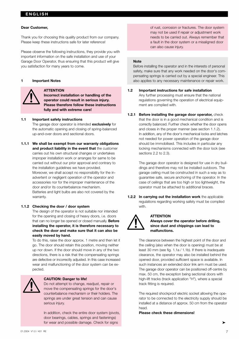
1.1.2 Checking the door / door systemThe design of the operator is not suitable nor intended for the opening and closing of heavy doors, i.e. doors that can no longer be opened or closed manually. Beforeinstalling the operator, it is therefore necessary to check the door and make sure that it can also be easily moved by hand.To do this, raise the door approx. 1 metre and then let itgo. The door should retain this position, moving neither up nor down. If the door should move in any of the two directions, there is a risk that the compensating springs are defective or incorrectly adjusted. In this case increasedwear and malfunctioning of the door system can be ex-pected.
CAUTION: Danger to life!Do not attempt to change, readjust, repair ormove the compensating springs for the door'scounterbalance mechanism or their holders. Thesprings are under great tension and can causeserious injury.
In addition, check the entire door system (pivots,door bearings, cables, springs and fastenings)for wear and possible damage. Check for signs
of rust, corrosion or fractures. The door systemmay not be used if repair or adjustment workneeds to be carried out. Always remember that a fault in the door system or a misaligned doorcan also cause injury.
NoteBefore installing the operator and in the interests of personalsafety, make sure that any work needed on the door's com-pensating springs is carried out by a special engineer. Thisalso applies to any necessary maintenance or repair work.
1.2 Important instructions for safe installationAny further processing must ensure that the national regulations governing the operation of electrical equip-ment are complied with.
1.2.1 Before installing the garage door operator, check that the door is in a good mechanical condition and is correctly balanced. Further check whether the door opensand closes in the proper manner (see section 1.1.2).In addition, any of the door's mechanical locks and latchesnot needed for power operation of the garage door should be immobilised. This includes in particular any locking mechanisms connected with the door lock (see sections 2.2 to 2.3).
The garage door operator is designed for use in dry buil-dings and therefore may not be installed outdoors. The garage ceiling must be constructed in such a way as to guarantee safe, secure anchoring of the operator. In the case of ceilings that are too high or too lightweight, the operator must be attached to additional braces.
1.2.2 In carrying out the installation work the applicable regulations regarding working safety must be complied with.
ATTENTIONAlways cover the operator before drilling,since dust and chippings can lead to malfunctions.
The clearance between the highest point of the door andthe ceiling (also when the door is opening) must be at least 30 mm (see fig. 1.1a / 1.1b). If there is inadequate clearance, the operator may also be installed behind theopened door, provided sufficient space is available. In such instances an extended door link arm must be used.The garage door operator can be positioned off-centre bymax. 50 cm, the exception being sectional doors with high-lift tracks (track application "H"), where a special track fitting is required.
The required shockproof electric socket allowing the ope-rator to be connected to the electricity supply should beinstalled at a distance of approx. 50 cm from the operatorhead.Please check these dimensions!
701.2004 V1.0 / 401 RE
E N G L I S H
NoteA caution notice warning about the trap risk must be permanently fixed in a conspicuous place close to the per-manently installed buttons used to actuate the operator.
1.3 Warnings
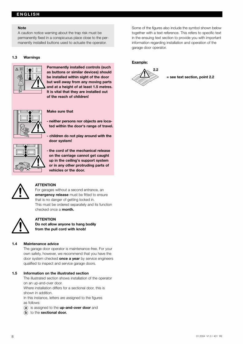
Permanently installed controls (suchas buttons or similar devices) shouldbe installed within sight of the doorbut well away from any moving partsand at a height of at least 1.5 metres.It is vital that they are installed out of the reach of children!
Make sure that
- neither persons nor objects are loca-ted within the door's range of travel.
- children do not play around with thedoor system!
- the cord of the mechanical release on the carriage cannot get caught up in the ceiling's support system or in any other protruding parts of vehicles or the door.
ATTENTIONFor garages without a second entrance, anemergency release must be fitted to ensurethat is no danger of getting locked in. This must be ordered separately and its functionchecked once a month.
ATTENTIONDo not allow anyone to hang bodilyfrom the pull cord with knob!
1.4 Maintenance adviceThe garage door operator is maintenance-free. For your own safety, however, we recommend that you have the door system checked once a year by service engineersqualified to inspect and service garage doors.
1.5 Information on the illustrated section The illustrated section shows installation of the operator on an up-and-over door.Where installation differs for a sectional door, this is shown in addition. In this instance, letters are assigned to the figures as follows:
Oa is assigned to the up-and-over door and
Ob to the sectional door.
Some of the figures also include the symbol shown belowtogether with a text reference. This refers to specific textin the ensuing text section to provide you with importantinformation regarding installation and operation of the garage door operator.
Example:
= see text section, point 2.2
8 01.2004 V1.0 / 401 RE
E N G L I S H
2.2
TABLE DES MATIERES PAGE
A Articles livrés 2B Outillage nécessaire au montage 2
1 Remarques importantes 101.1 Consignes importantes de sécurité 101.1.1 Le fabricant n'acceptera... 101.1.2 Contrôle de la porte / de l’installation de porte 101.2 Consignes importantes de sécurité pour le montage 101.2.1 Avant d’installer la motorisation 101.2.2 Lors des travaux de montage 101.3 Avertissement 111.4 Consignes d’entretien 111.5 Description fonctionnelle 11
Partie illustrée 15-27
2 Notice de montage 422.1 Dégagement requis pour le montage
de la motorisation 422.2 Verrouillages sur les portes basculantes 422.3 Verrouillages sur les portes sectionnelles 422.4 Portes basculantes avec une poignée en
ferronnerie d'art 422.5 Verrouillage central sur les portes sectionnelles 422.6 Profil de renfort excentrique sur les portes
sectionnelles 422.7 Tension du moyen d'entraînement 42
3 Mise en service / connexion de composants additionnels / fonctionnement 42
3.1 Fixation de la position finale "porte fermée" par le montage de la butée 42
3.2 Conseils pour les travaux d'électricité 423.3 Mise en service de la motorisation 423.3.1 Réinitialisation des données de porte 433.3.2 Apprentissage de l'entraînement 433.3.3 Réglage des efforts maximaux 433.3.4 Réglage de la vitesse de marche 443.4 Autres possibilités de réglage 443.5 Connexion de composants additionnels 443.5.1 Montage du récepteur 453.5.2 Connexion d'un bouton-poussoir à impulsion
externe 453.5.3 Connexion d'un coupe-circuit ou d'un contact
de portillon incorporé 453.5.4 Connexion d'une cellule photoélectrique 453.5.5 Connexion d'une sécurité de contact 453.5.6 Connexion d'un relais supplémentaire pour
la commande d'éclairage 453.6 Conseils pour l'utilisation de la motorisation
de garage 453.6.1 Utilisation normale 463.6.2 Utilisation après actionnement du déverrouillage
mécanique 463.6.3 Messages d'erreur lampe de motorisation /
LED de diagnostic 463.6.4 Mesures à prendre en cas de message d'erreur 47
3.7 Pannes et dépannage 473.7.1 La motorisation ne fonctionne pas 473.7.2 La motorisation ne fonctionne pas avec l'émetteur 47 3.7.3 La motorisation ne fonctionne pas avec
des boutons-poussoirs externes connectés 473.7.4 La porte ne se ferme ou ne s'ouvre pas
complètement 473.7.5 La motorisation réagit, mais la porte ne
s'ouvre pas 473.7.6 La porte inverse son mouvement en cours
de fermeture 483.7.7 Panne d'éclairage 483.7.8 Portée trop faible de l'émetteur 48
4 Conditions de garantie 48
5 Caractéristiques techniques 48
6 Démontage et mise en décharge 49
Droits d'auteur réservés. Reproduction même partielle uniquement avec notre autorisation.Changements de construction réservés.
901.2004 V1.0 / 401 RE
F R A N Ç A I S
Cher client,
Nous vous félicitons d'avoir porté votre choix sur l'un des pro-duits de haute qualité de notre société. Veuillez conserver soig-neusement la présente notice.
Respectez les consignes ci-après, qui vous fournissent desinformations importantes pour le montage et la commande devotre motorisation pour porte de garage. Vous pourrez ainsiprofiter de ce produit pendant de nombreuses années.
1. Remarques importantes
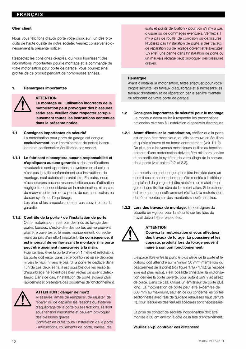
ATTENTIONLe montage ou l'utilisation incorrects de lamotorisation peut provoquer des blessuressérieuses. Veuillez donc respecter scrupu-leusement toutes les instructions contenuesdans la présente notice.
1.1 Consignes importantes de sécurité La motorisation pour porte de garage est conçue exclusivement pour l'entraînement de portes bascu-lantes et sectionnelles équilibrées par ressort.
1.1.1 Le fabricant n'acceptera aucune responsabilité et n'appliquera aucune garantie si des modifications structurelles sont apportées au système ou si celui-ci n'est pas installé conformément aux instructions de montage, sauf autorisation préalable. En outre, nous n'accepterons aucune responsabilité en cas d'utilisation négligente ou inconsidérée de la motorisation, ni en cas de mauvais entretien de la porte, de ses accessoires ou de son système d'équilibrage.Les piles et les ampoules ne sont pas couvertes par la garantie.
1.1.2. Contrôle de la porte / de l’installation de porteCette motorisation n'est pas destinée au levage des portes lourdes, c’est-à-dire des portes qui ne peuvent plus être ouvertes et fermées manuellement, ou seule-ment au prix d'un effort important. En conséquence, ilest impératif de vérifier avant le montage si la portepeut être aisément manœuvrée à la main.Pour ce faire, levez la porte d'environ 1 mètre et relâchez-la.La porte doit rester dans cette position et ne se déplacerni vers le haut, ni vers le bas. Si la porte se déplace dansl'un de ces deux sens, il est possible que les ressorts d'équilibrage ne soient pas bien réglés ou soient défec-tueux. Dans ce cas, l'installation de porte s'usera plus rapidement et présentera des problèmes de fonctionnement.
ATTENTION : danger de mort!N'essayez jamais de remplacer, de rajuster, deréparer ou de déplacer les ressorts du systèmed'équilibrage de la porte ou ses fixations. Ils sontsous tension importante et peuvent provoquerdes blessures graves.Contrôlez en outre toute l'installation de la porte- articulations, roulements de porte, câbles, res
sorts et points de fixation - pour voir s'il n'y a pasd'usure ou de dommages éventuels. Vérifiez s'iln'y a pas de rouille, de corrosion ou de fissures.N’utilisez pas l'installation de porte si des travauxde réparation ou de réglage doivent être exécutés.En effet, une panne dans l'installation de porte ouun mauvais réglage peut provoquer des blessuresgraves.
RemarqueAvant d'installer la motorisation, faites effectuer, pour votre propre sécurité, les travaux d’équilibrage et si nécessaire lestravaux d'entretien et de réparation par le service clientèle du fabricant de votre porte de garage!
1.2 Consignes importantes de sécurité pour le montageLe monteur devra veiller à respecter les prescriptions nationales relatives à l'installation d'appareils électriques.
1.2.1 Avant d'installer la motorisation, vérifiez que la porte est en bon état mécanique, qu'elle se trouve en équilibreet qu'elle s'ouvre et se ferme correctement (voir 1.1.2).De plus, tous les verrous mécaniques inutiles au fonction-nement d'une motorisation doivent être mis hors serviceet en particulier le système de verrouillage de la serrure de la porte (voir points 2.2 et 2.3).
La motorisation est conçue pour être installée dans un endroit sec et ne peut donc pas être montée à l'extérieur. Le plafond du garage doit être réalisé en un matériau qui garantit une fixation sûre de la motorisation. Si le plafondest trop haut ou insuffisamment résistant, la motorisation doit être montée sur des montants supplémentaires.
1.2.2 Lors des travaux de montage, les consignes de sécurité en vigueur pour la sécurité sur les lieux detravail doivent être respectées.
ATTENTIONCouvrez la motorisation si vous effectuez des travaux de forage. La poussière et les copeaux produits lors du forage peuvent nuire à son bon fonctionnement.
L'espace libre entre le point le plus élevé de la porte et leplafond doit atteindre au minimum 30 mm (même lors dubasculement de la porte) (voir figure 1.1a / 1.1b). Si l'espacelibre est plus réduit, il est possible d'installer la motorisa-tion derrière la porte ouverte, pour autant qu'il y ait assezde place. Dans ce cas, utilisez un entraîneur de porte pluslong. La motorisation de porte peut être excentrée de500 mm au maximum, sauf en ce qui concerne les portessectionnelles avec rails de guidage rehaussés haut (ferrureH), pour lesquelles des ferrures spéciales sont nécessaires.
La prise de contact de sécurité indispensable doit être montée à 50 cm environ à côté de la tête d'entraînement.
Veuillez s.v.p. contrôler ces distances!
10 01.2004 V1.0 / 401 RE
F R A N Ç A I S
RemarqueDes panneaux d'avertissement (risque de pincement) doi-vent être placés à demeure à un endroit bien visible ou àproximité des boutons-poussoirs fixes de la commande.
1.3 Avertissement
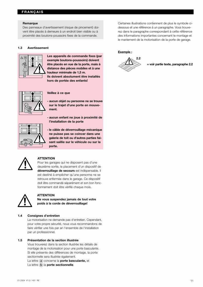
Les appareils de commande fixes (parexemple boutons-poussoirs) doivent être placés en vue de la porte, mais à distance des pièces mobiles et à une hauteur minimale de 1,5 m.Ils doivent absolument être installéshors de portée des enfants!
Veillez à ce que
- aucun objet ou personne ne se trouvesur le trajet d'une porte en mouve-ment.
- aucun enfant ne joue à proximité del’installation de la porte
- le câble de déverrouillage mécaniquene puisse pas se coincer dans unegalerie de toit ou d'autres parties fai-sant saillie sur le véhicule ou sur laporte.
ATTENTIONPour les garages qui ne disposent pas d'une deuxième sortie, le placement d'un dispositif de déverrouillage de secours est indispensable. Il est destiné à empêcher qu’une personne ne se retrouve enfermée dans le garage. Ce dispositif doit être commandé séparément et son bon fonc-tionnement doit être vérifié chaque mois.
ATTENTIONNe vous suspendez jamais de tout votrepoids à la corde de déverrouillage!
1.4 Consignes d’entretienLa motorisation ne demande pas d'entretien. Cependant,pour votre propre sécurité, nous vous recommandons defaire vérifier une fois par an l'ensemble de l'installation par un professionnel.
1.5 Présentation de la section illustréeVous trouverez dans la section illustrée les détails de montage de la motorisation pour une porte basculante.Si elle présente des différences de montage, la porte sectionnelle sera illustrée également. La lettre Oa concerne la porte basculante, et La lettre Ob la porte sectionnelle.
Certaines illustrations contiennent de plus le symbole ci-dessous et une référence à un paragraphe. Vous trouve-rez dans le paragraphe correspondant à cette référence des informations importantes concernant le montage et le maniement de la motorisation de la porte de garage.
Exemple :
= voir partie texte, paragraphe 2.2
1101.2004 V1.0 / 401 RE
F R A N Ç A I S
2.2
SOMMARIO PAGINA
A Articoli in dotazione 2B Attrezzi necessari per il montaggio 2
1 Importanti avvertenze 131.1 Importanti avvertenze per la Sua sicurezza 131.1.1 Noi siamo sollevati dalla garanzia e dalla respon-
sabilità per il prodotto qualora… 131.1.2 Controllo della porta 131.2 Avvertenze importanti per un montaggio sicuro 131.2.1 Prima del montaggio 131.2.2 Durante i lavori di montaggio 131.3 Avvertimenti 141.4 Avvertenze per la manutenzione 141.5 Indicazioni per la parte illustrata 14
Parte illustrata 15-27
2 Istruzioni per il montaggio 502.1 Spazio libero necessario per il montaggio della
motorizzazione 502.2 Dispositivi di bloccaggio sulla porta basculante 502.3 Dispositivi di bloccaggio sul portone sezionale 502.4 Porte basculanti con maniglia in ferro battuto 502.5 Portone sezionale con serratura centrale 502.6 Portone sezionale con profilo di rinforzo applicato
fuori asse 502.7 Tensionamento del mezzo di azionamento 50
3 Messa in funzione / collegamento di componenti supplementari / funzionamento 50
3.1 Stabilire la posizione di fine corsa "Chiusura" tramite montaggio dell'arresto di fine corsa 50
3.2 Avvertenze per gli interventi sull'impianto elettrico 503.3 Messa in funzione della motorizzazione 503.3.1 Cancellazione dei dati della porta 513.3.2 Procedura di apprendimento della motorizzazione 51 3.3.3 Impostazione degli sforzi massimi 513.3.4 Regolazione della velocità di scorrimento 52 3.4 Altre possibilità di regolazione 523.5 Collegamento di componenti supplementari 523.5.1 Montaggio del radioricevitore 533.5.2 Collegamento di tastiere esterne ad "impulso" 533.5.3 Collegamento di un interruttore o contatto porta
pedonale 533.5.4 Collegamento di una fotocellula 533.5.5 Collegamento di una costola di sicurezza 533.5.6 Collegamento di un relè supplementare per il
comando luce 533.6 Avvertenze per il funzionamento della moto-
rizzazione 533.6.1 Funzionamento normale 543.6.2 Funzionamento dopo l'azionamento dello
sbloccaggio meccanico 543.6.3 Messaggi d'errore della lampada della
motorizzazione / LED diagnostica 543.6.4 Interventi dopo il messaggio d'errore 553.7 Malfunzionamenti e rimedio 55
3.7.1 La motorizzazione non gira 553.7.2 La motorizzazione non funziona con telecomando 553.7.3 La motorizzazione non funziona con tastiere
allacciate all'esterno 553.7.4 La porta non si apre o chiude completamente 553.7.5 La motorizzazione reagisce, ma la porta non
si apre 553.7.6 La porta fa inversione di marcia durante la
manovra di chiusura 553.7.7 Luce difettosa 553.7.8 Raggio d'azione del radiocomando troppo breve 55
4 Garanzia 56
5 Dati tecnici 56
6 Smontaggio e smaltimento 56
Diritti d'autore riservati.Riproduzione, anche solo parziale, previa nostra approvazione.La Ditta si riserva di apportare modifiche al prodotto.
12 01.2004 V1.0 / 401 RE
I TA L I A N O
1301.2004 V1.0 / 401 RE
Gentile cliente,
siamo lieti che Lei abbia scelto un prodotto di nostra produzione.
La preghiamo di conservare queste istruzioni con cura e di leg-gere attentamente le seguenti avvertenze, che Le fornirannoimportanti informazioni sull'installazione e sull'uso della motori-zzazione. Siamo certi che questo prodotto Le procurerà grandesoddisfazione per molti anni.
1 Importanti avvertenze
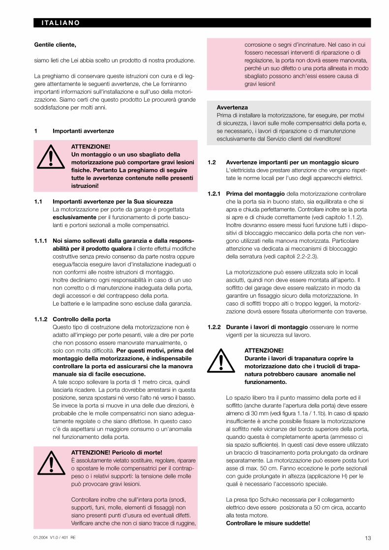
ATTENZIONE!Un montaggio o un uso sbagliato dellamotorizzazione può comportare gravi lesionifisiche. Pertanto La preghiamo di seguiretutte le avvertenze contenute nelle presentiistruzioni!
1.1 Importanti avvertenze per la Sua sicurezzaLa motorizzazione per porte da garage è progettata esclusivamente per il funzionamento di porte bascu-lanti e portoni sezionali a molle compensatrici.
1.1.1 Noi siamo sollevati dalla garanzia e dalla respons-abilità per il prodotto qualora il cliente effettui modifichecostruttive senza previo consenso da parte nostra oppureesegua/faccia eseguire lavori d'installazione inadeguati onon conformi alle nostre istruzioni di montaggio.Inoltre decliniamo ogni responsabilità in caso di un uso non corretto o di manutenzione inadeguata della porta, degli accessori e del contrappeso della porta.Le batterie e le lampadine sono escluse dalla garanzia.
1.1.2 Controllo della portaQuesto tipo di costruzione della motorizzazione non è adatto all'impiego per porte pesanti, vale a dire per porteche non possono essere manovrate manualmente, o solo con molta difficoltà. Per questi motivi, prima del montaggio della motorizzazione, è indispensabile controllare la porta ed assicurarsi che la manovra manuale sia di facile esecuzione.A tale scopo sollevare la porta di 1 metro circa, quindi lasciarla ricadere. La porta dovrebbe arrestarsi in questaposizione, senza spostarsi né verso l'alto né verso il basso.Se invece la porta si muove in una delle due direzioni, è probabile che le molle compensatrici non siano adegua-tamente regolate o che siano difettose. In questo caso c'è da aspettarsi un maggiore consumo o un'anomalia nel funzionamento della porta.
ATTENZIONE! Pericolo di morte!È assolutamente vietato sostituire, regolare, riparareo spostare le molle compensatrici per il contrap-peso o i relativi supporti: la tensione delle mollepuò provocare gravi lesioni.
Controllare inoltre che sull'intera porta (snodi,supporti, funi, molle, elementi di fissaggi) nonsiano presenti punti d’usura ed eventuali difetti.Verificare anche che non ci siano tracce di ruggine,
corrosione o segni d’incrinature. Nel caso in cuifossero necessari interventi di riparazione o diregolazione, la porta non dovrà essere manovrata,perché un suo difetto o una porta allineata in modosbagliato possono anch'essi essere causa digravi lesioni!
AvvertenzaPrima di installare la motorizzazione, far eseguire, per motividi sicurezza, i lavori sulle molle compensatrici della porta e,se necessario, i lavori di riparazione o di manutenzioneesclusivamente dal Servizio clienti del rivenditore!
1.2 Avvertenze importanti per un montaggio sicuroL'elettricista deve prestare attenzione che vengano rispet-tate le norme locali per l'uso degli apparecchi elettrici.
1.2.1 Prima del montaggio della motorizzazione controllare che la porta sia in buono stato, sia equilibrata e che si apra e chiuda perfettamente. Controllare inoltre se la portasi apre e di chiude correttamente (vedi capitolo 1.1.2).Inoltre dovranno essere messi fuori funzione tutti i dispo-sitivi di bloccaggio meccanico della porta che non ven-gono utilizzati nella manovra motorizzata. Particolare attenzione va dedicata ai meccanismi di bloccaggio della serratura (vedi capitoli 2.2-2.3).
La motorizzazione può essere utilizzata solo in locali asciutti, quindi non deve essere montata all'aperto. Il soffitto del garage deve essere realizzato in modo da garantire un fissaggio sicuro della motorizzazione. In caso di soffitti troppo alti o troppo leggeri, la motoriz-zazione dovrà essere fissata ulteriormente con traverse.
1.2.2 Durante i lavori di montaggio osservare le norme vigenti per la sicurezza sul lavoro.
ATTENZIONE! Durante i lavori di trapanatura coprire lamotorizzazione dato che i trucioli di trapa-natura potrebbero causare anomalie nel funzionamento.
Lo spazio libero tra il punto massimo della porte ed il soffitto (anche durante l'apertura della porta) deve esserealmeno di 30 mm (vedi figura 1.1a / 1.1b). In caso di spazioinsufficiente è anche possibile fissare la motorizzazione al soffitto nelle vicinanze del bordo superiore della porta,quando questa è completamente aperta (ammesso ci sia spazio sufficiente). In questi casi deve essere utilizzatoun braccio di trascinamento porta prolungato da ordinareseparatamente. La motorizzazione può essere posta fuoriasse di max. 50 cm. Fanno eccezione le porte sezionali con guide prolungate in altezza (applicazione H) per le quali è necessario l'accessorio speciale.
La presa tipo Schuko necessaria per il collegamento elettrico deve essere posizionata a 50 cm circa, accanto alla testa motore.Controllare le misure suddette!
I TA L I A N O
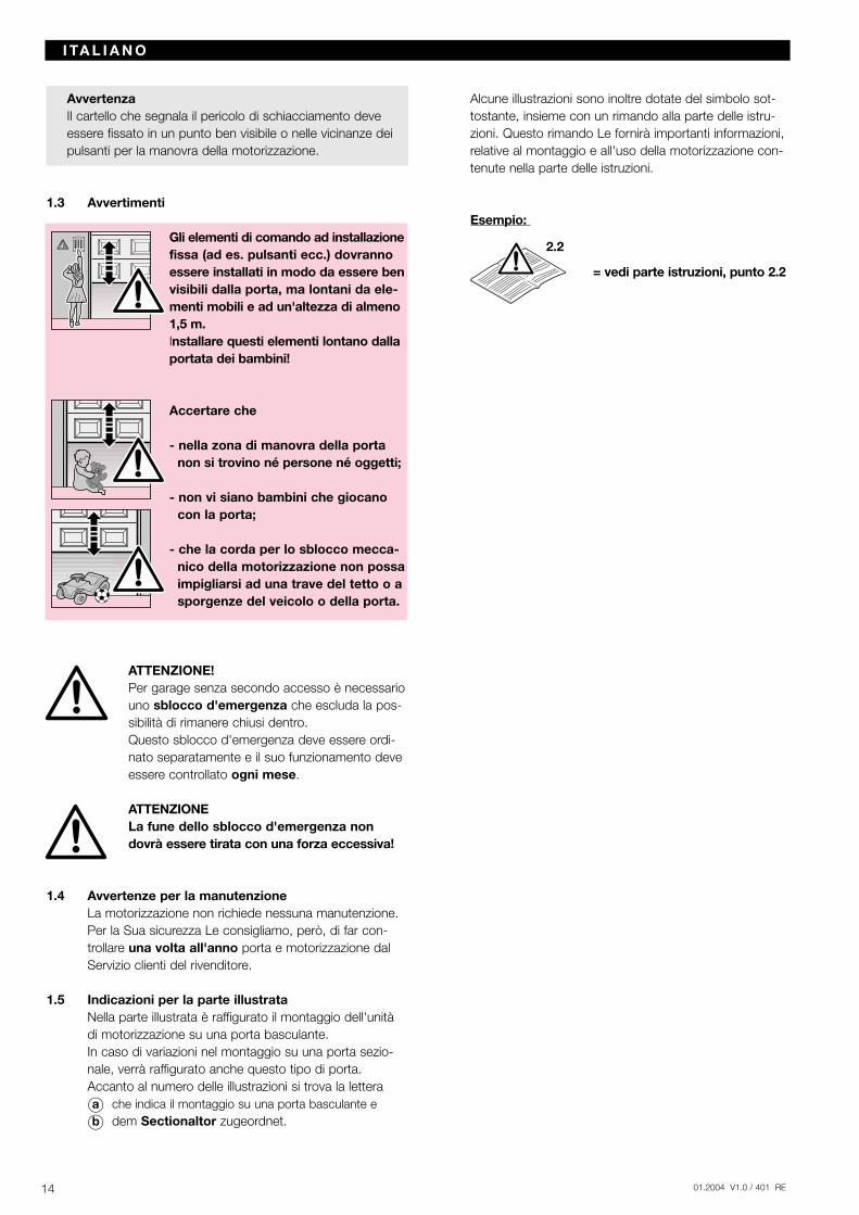
AvvertenzaIl cartello che segnala il pericolo di schiacciamento deveessere fissato in un punto ben visibile o nelle vicinanze deipulsanti per la manovra della motorizzazione.
1.3 Avvertimenti
Gli elementi di comando ad installazionefissa (ad es. pulsanti ecc.) dovrannoessere installati in modo da essere benvisibili dalla porta, ma lontani da ele-menti mobili e ad un'altezza di almeno1,5 m.Installare questi elementi lontano dallaportata dei bambini!
Accertare che
- nella zona di manovra della porta non si trovino né persone né oggetti;
- non vi siano bambini che giocano con la porta;
- che la corda per lo sblocco mecca-nico della motorizzazione non possaimpigliarsi ad una trave del tetto o asporgenze del veicolo o della porta.
ATTENZIONE! Per garage senza secondo accesso è necessariouno sblocco d'emergenza che escluda la pos-sibilità di rimanere chiusi dentro.Questo sblocco d'emergenza deve essere ordi-nato separatamente e il suo funzionamento deveessere controllato ogni mese.
ATTENZIONELa fune dello sblocco d'emergenza nondovrà essere tirata con una forza eccessiva!
1.4 Avvertenze per la manutenzioneLa motorizzazione non richiede nessuna manutenzione. Per la Sua sicurezza Le consigliamo, però, di far con-trollare una volta all'anno porta e motorizzazione dal Servizio clienti del rivenditore.
1.5 Indicazioni per la parte illustrataNella parte illustrata è raffigurato il montaggio dell'unità di motorizzazione su una porta basculante.In caso di variazioni nel montaggio su una porta sezio-nale, verrà raffigurato anche questo tipo di porta.Accanto al numero delle illustrazioni si trova la lettera
Oa che indica il montaggio su una porta basculante e
Ob dem Sectionaltor zugeordnet.
Alcune illustrazioni sono inoltre dotate del simbolo sot-tostante, insieme con un rimando alla parte delle istru-zioni. Questo rimando Le fornirà importanti informazioni, relative al montaggio e all'uso della motorizzazione con-tenute nella parte delle istruzioni.
Esempio:
= vedi parte istruzioni, punto 2.2
14 01.2004 V1.0 / 401 RE
I TA L I A N O
2.2
1501.2004 V1.0 / 401 RE
1a
1.2a
1.3a
30
1.1a
2.2
1.2.2
1.2a1.3a
1.2a1.3a
01.2004 V1.0 / 401 RE16
1b
1.2b
1.4b1.5b1.6b
1.2b
1.2b
1.4b1.5b1.6b
1.3b
30
1.1b
1.3b
2.3
1.2.2 2.3
01.2004 V1.0 / 401 RE 17
1 / 2
1 / 2
B
2a
Ø 5
2.4
15
1.4b
1.5b
1.6b
01.2004 V1.0 / 401 RE18
A
B
1/2
1/2
1/2 1/2
90
1/2 1/2
3.1a
3.2a
3.3a
B
1/2
1/2 1/2 1/2
3.4a
N 80
N 80
DF 98
F 80
A
1/2
1/2
Ø 10
Ø 10
2.4
67
1/2 1/2
60
01.2004 V1.0 / 401 RE 19
A
A
LTE/LPU/LTH 403.1b
3.2b
≥113
Ø 10
Ø 10
55
60
LTE/LPU/LTH 40
> 55
B
Ø 5
2b 2.5
01.2004 V1.0 / 401 RE20
4.1
4.2 4.3 3.1
4
4.1
4.2/4.3
01.2004 V1.0 / 401 RE 21
5.1
5.2-5.4
5.5
5
5.1 5.2 5.3
5.4 5.5
D
300 max.
A
Ø 10
C
60
01.2004 V1.0 / 401 RE22
E
E
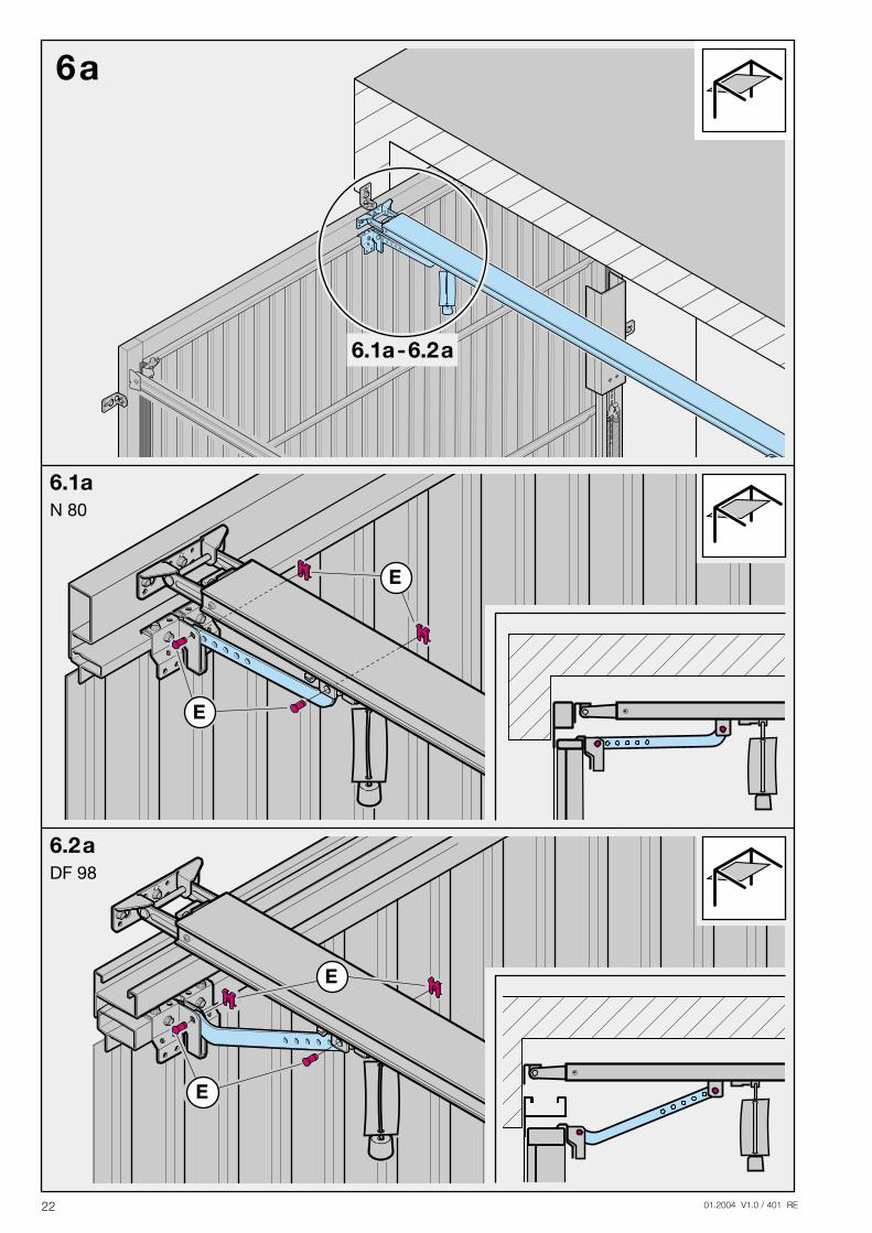
6.1a-6.2a
6a
6.2aDF 98
6.1a
E
E
N 80
01.2004 V1.0 / 401 RE 23
E
E
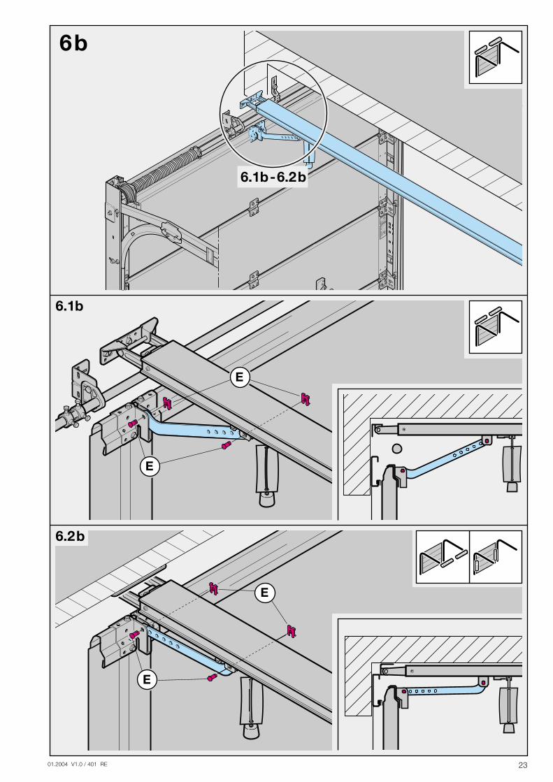
6.1b-6.2b
6b
6.2b
6.1b
E
E
01.2004 V1.0 / 401 RE24
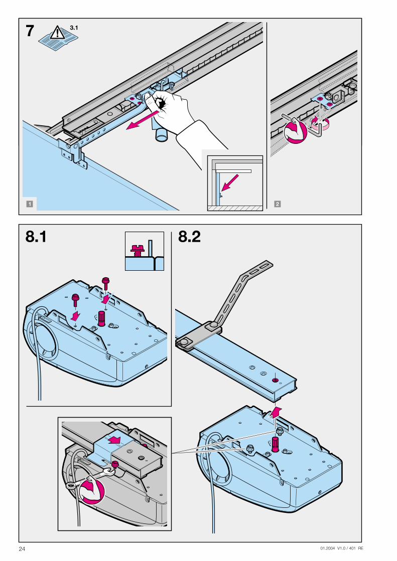
8.1 8.2
7 3.1
01.2004 V1.0 / 401 RE 25
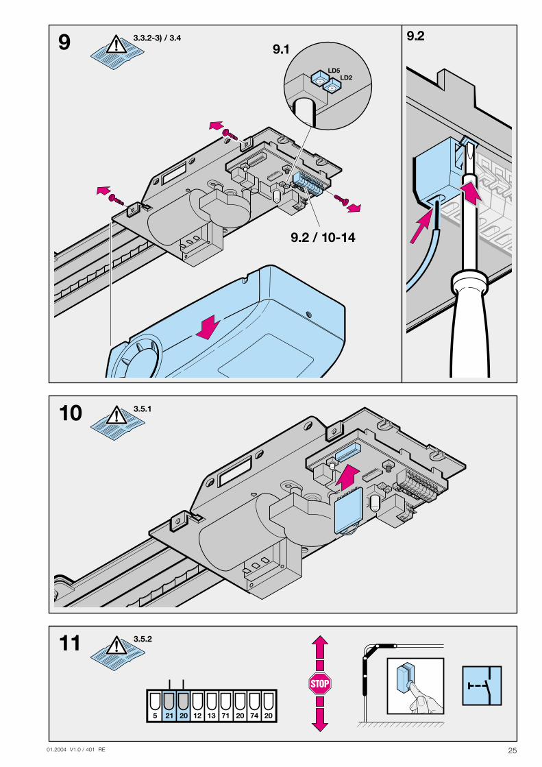
9.2 / 10-14
LD5LD2
9 9.29.1
3.3.2-3) / 3.4
10 3.5.1
11 3.5.2
5 21 20 12 13 71 20 74 20
01.2004 V1.0 / 401 RE26
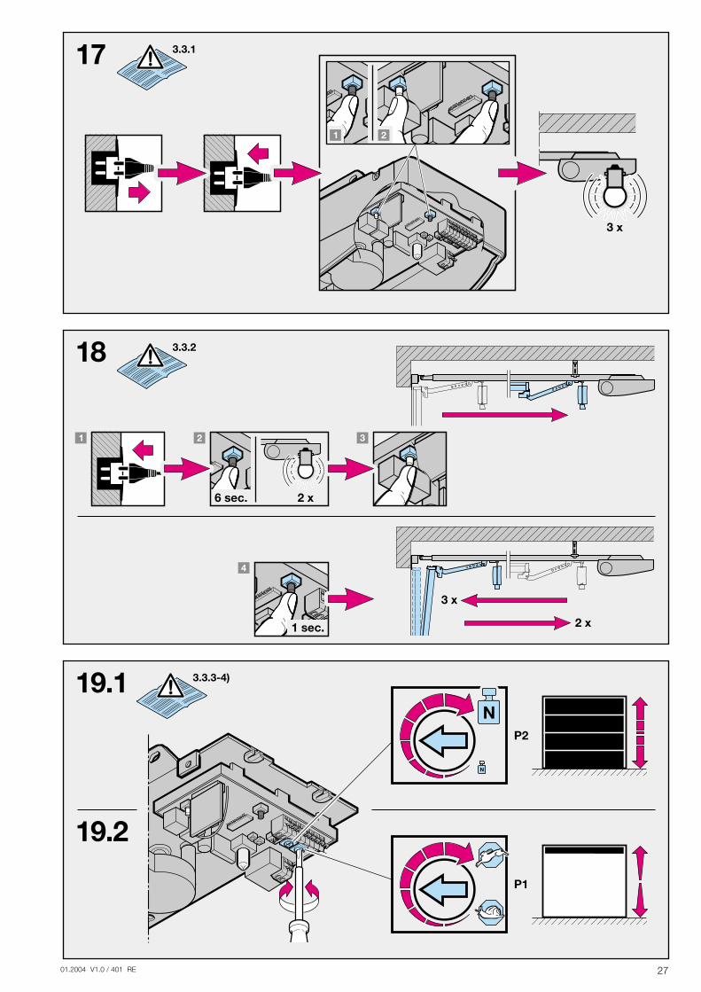
15
16 3.3.2-1) / 3.6.2
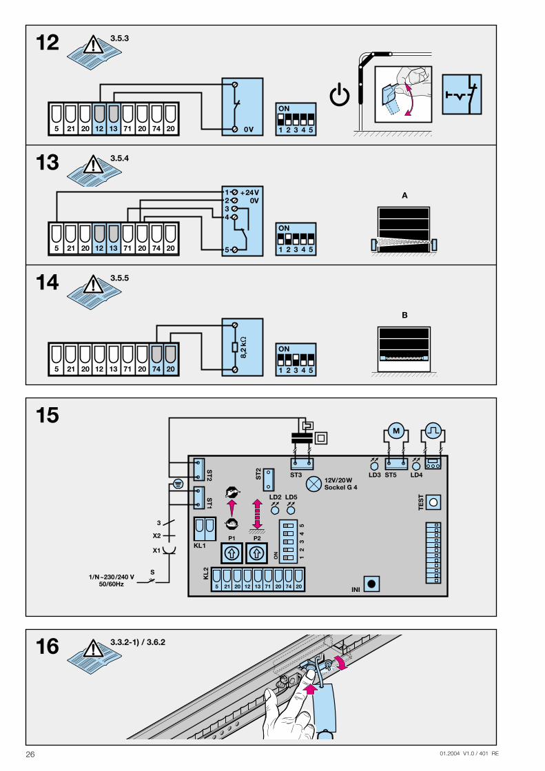
12 3.5.3
0V5 21 20 12 13 71 20 74 20
ON
1 2 3 4 5
3
X2
X1
S1/N~230/240 V
50/60Hz
P1
M
LD5
5 21 20 12 13 71 20 74 20
LD2
P2
12
3
ON
45
INI
KL
2
TE
ST
12V/20WSockel G 4
LD4LD3
KL1
ST5ST3ST
2ST
2S
T1
13 3.5.4
14 3.5.5
8,2
k
ON
1 2 3 4 55 21 20 12 13 71 20 74 20
B
+24V
ON
1 2 3 4 5
0V
5 21 20 12 13 71 20 74 20
1234
5
A
01.2004 V1.0 / 401 RE 27
18 3.3.2
17 3.3.1
19.1
19.2
3.3.3-4)
1 sec.
3 x
3 x
2 x
2 x6 sec.
01.2004 V1.0 / 401 RE28
D E U T S C H
2 Montageanleitung
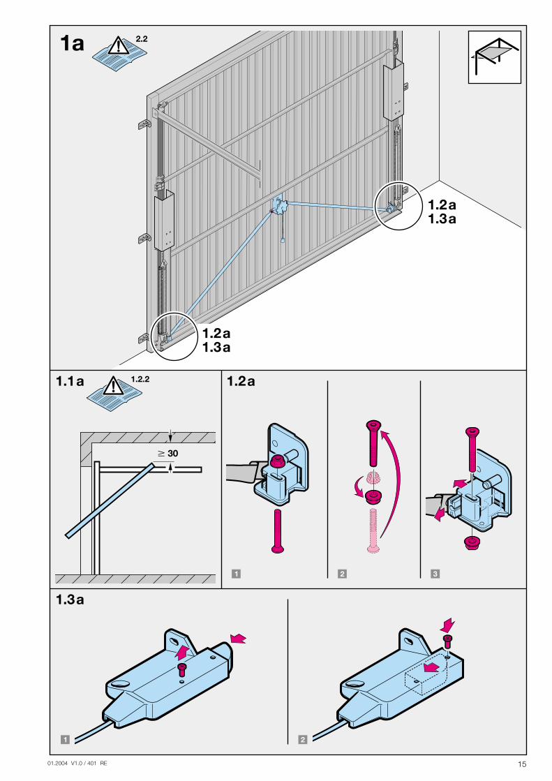
2.1 Benötigter Freiraum für die Montage des AntriebesBei der Antriebs-Montage muss der Freiraum zwischen dem höchsten Punkt beim Torlauf und der Decke mind.30 mm betragen (siehe Bild 1.1a / 1.1b).
2.2 Die mechanischen Tor-Verriegelungen am Schwingtorsind außer Betrieb zu setzen (siehe Bild 1a). Bei den hiernicht aufgeführten Tormodellen sind die Schnäpper bauseits festzustellen.
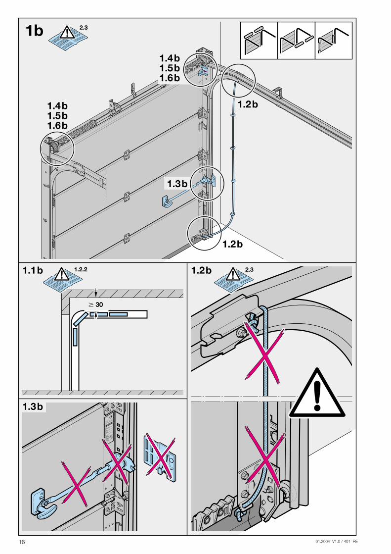
2.3 Am Sectionaltor ist die mechanische Torinnenverriege-lung komplett zu demontieren (siehe Bild 1b).
ACHTUNGBei der Antriebs-Montage muss dasHandseil entfernt werden(siehe Bild 1.2b)
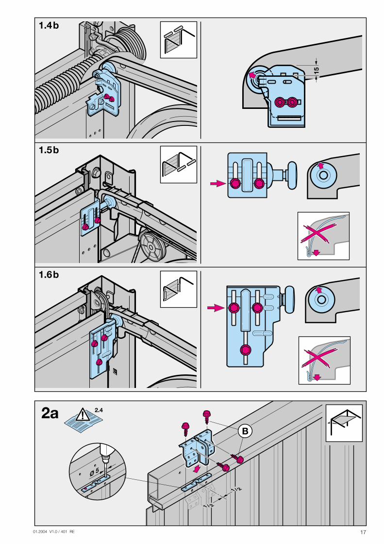
2.4 HinweisSchwingtore mit einem kunstschmiedeeisernenTorgriff Abweichend vom Bildteil (siehe Bild 2a / 3.2a) sind bei diesen Toren die Sturzgelenkbefestigung und der Mitnehmerwinkel außermittig anzubringen.
2.5 Mittiger Torverschluss am SectionaltorBei Sectionaltoren mit einem mittigen Torverschluss ist die Sturzgelenkbefestigung und der Mitnehmerwinkel außermittig anzubringen (siehe Bild 2b).
2.6 Außermittiges Verstärkungsprofil am SectionaltorBeim außermittigen Verstärkungsprofil am Sectionaltor ist der Mitnehmerwinkel am nächstgelegenen Verstärkungs-profil rechts oder links zu montieren (siehe Bild 2b).
2.7 Spannung des AntriebmediumsDer Zahnriemen, bzw. die Kette der Antriebsschiene be-sitzt eine werkseitige optimale Vorspannung. In der Anfahr-und Abbremsphase kann es bei großen Toren zu einemkurzeitigen Heraushängen des Riemens bzw. der Ketteaus dem Schienenprofil kommen. Dieser Effekt bringtjedoch keine technischen Einbußen mit sich und wirktsich auch nicht nachteilig auf die Funktion und Lebens-dauer des Antriebes aus.
ACHTUNGGreifen Sie nicht während einer Torfahrtmit den Fingern in die Führungsschiene Quetschgefahr!
3 Inbetriebnahme / Anschluss von Zusatzkomponenten / Betrieb
3.1 Festlegen der Tor-Endlage "Tor-Zu" durch die Montage des Endanschlages1) Den Endanschlag für die Endlage "Tor-Zu" ist zwischen
dem Führungsschlitten und dem Tor lose in die Füh-rungsschiene einzusetzen (siehe Bild 4) und das Tor istper Hand in die Endlage "Tor-Zu" zu schieben der
Endanschlag wird dadurch in richtigen Position ge-schoben (siehe Bild 7).
2) Den Endanschlag für die Endlage Tor-Zu" anschließend fixieren (siehe Bild 7).
HinweisWenn sich das Tor per Hand nicht einfach in die gewünschteEndlage "Tor-Auf" bzw. "Tor-Zu" schieben lässt, so ist die Tor-mechanik für den Betrieb mit dem Garagentorantrieb zuschwergängig und muss überprüft werden (siehe Kapitel 1.1.2)!
3.2 Hinweise für Elektro-Arbeiten
ACHTUNGBei sämtlichen Elektro-Arbeiten, sindfolgende Punkte zu beachten:
- Elektroanschlüsse dürfen nur von einer Elektro-fachkraft durchgeführt werden!
- Die bauseitige Elektroinstallation muss denjeweiligen Schutzbestimmungen entsprechen(230/240 V AC, 50/60 Hz)!
- Vor allen Arbeiten am Antrieb ist der Netzstecker zu ziehen!
- Fremdspannung an den Anschlussklemmen der Steuerung führt zu einer Zerstörung der Elektronik!
- Zur Vermeidung von Störungen ist darauf zuachten, dass die Steuerleitungen des Antriebes(24 V DC) in einem getrennten Installations-Systemzu anderen Versorgungsleitungen (230 V AC) zu verlegen sind!
3.3 Inbetriebnahme des AntriebesDer Antrieb hat einen spannungsausfallsicheren Speicher,in dem beim Einlernen die torspezifischen Daten (Ver-fahrweg, während der Torfahrt benötigte Kräfte usw.) abgelegt und bei darauf folgenden Torfahrten aktualisiertwerden. Diese Daten sind nur für dieses Tor gültig und müssen daher für einen Einsatz an einem anderen Tor oder wenn sich das Tor in seinem Laufverhalten stark geändert hat (z.B. bei nachträglichem Versetzen des Endanschlages oder dem Einbau neuer Federn usw.), neu eingelernt werden.
ACHTUNGDie erste Inbetriebnahme erfolgt durcheinen Sachkundigen. Die Inbetriebnahme ist schriftlich zu protokollieren. Der Antriebist nur ein Teil eines Tores. Die für dieGesamtanlage "Tor" verantwortliche Firmastellt die Konformitätserklärung aus undbringt das CE-Zeichen an. Durch das An-bringen des CE-Zeichens am Tor und dasAusstellen der EG-Konformitätserklärungwird die Einhaltung der EG-Maschinen-richtlinie dokumentiert.
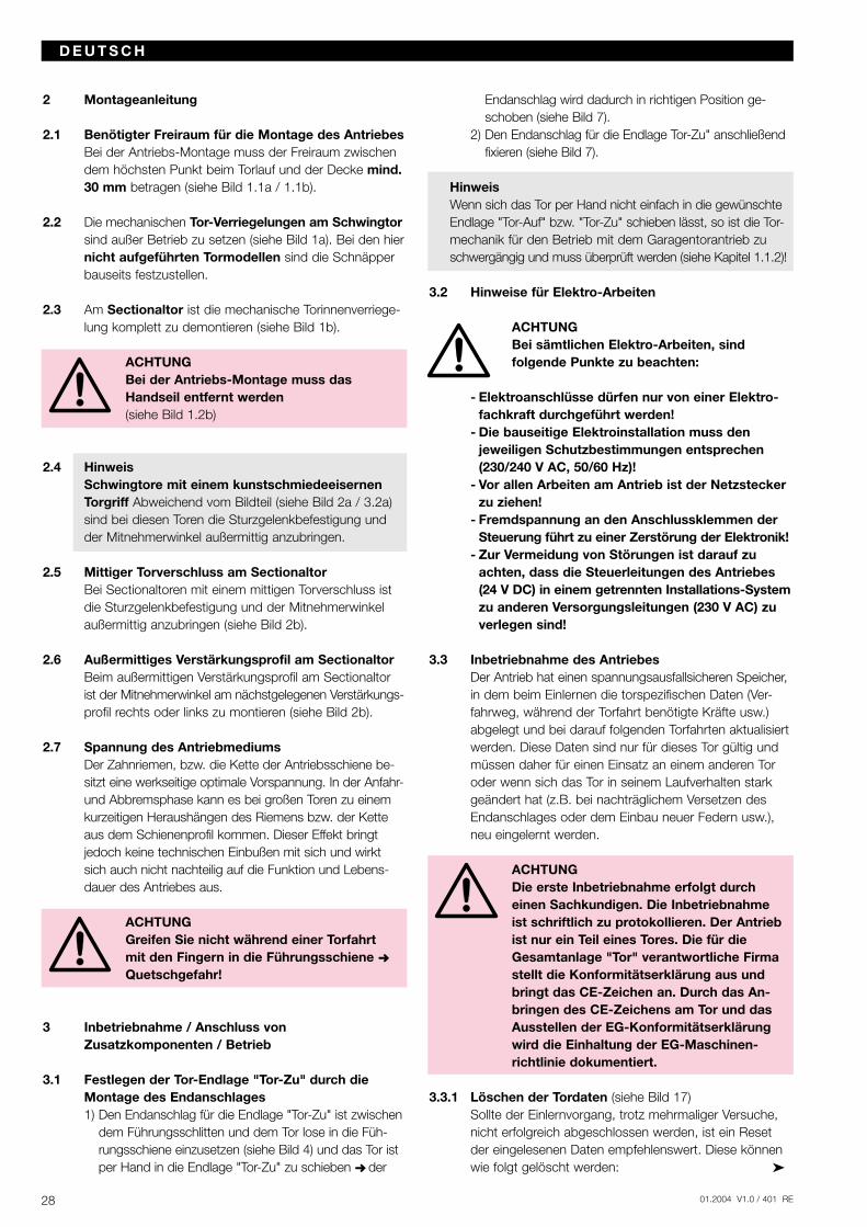
3.3.1 Löschen der Tordaten (siehe Bild 17)Sollte der Einlernvorgang, trotz mehrmaliger Versuche, nicht erfolgreich abgeschlossen werden, ist ein Reset der eingelesenen Daten empfehlenswert. Diese können wie folgt gelöscht werden:
01.2004 V1.0 / 401 RE 29
HinweisSollte die Kraft bzw. die Geschwindigkeit für die Lernfahrtnicht ausreichen, kann über DIL 4 die Kraft/Geschwindigkeitvon 30 % auf 50 % erhöht werden. Den Einlernvorgangerneut starten.Bei Sectionaltoren empfehlen wir, den DIL 4 vor derLernphase auf "OFF" zu stellen.
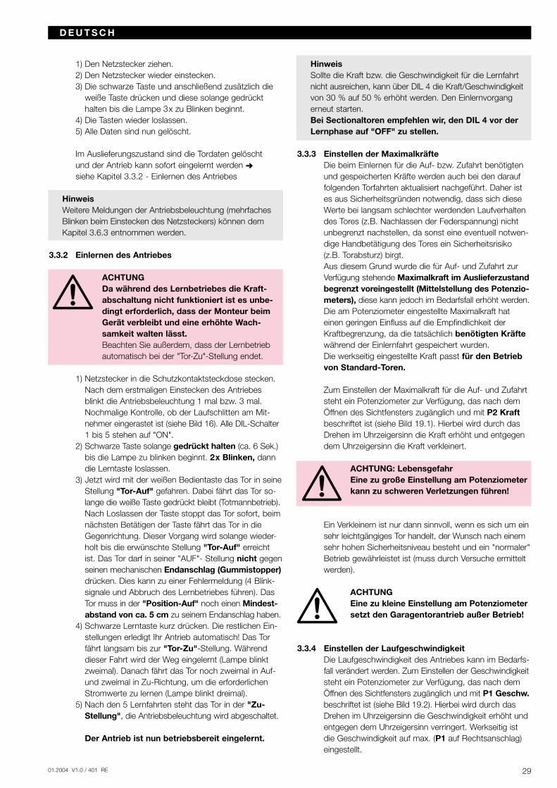
3.3.3 Einstellen der MaximalkräfteDie beim Einlernen für die Auf- bzw. Zufahrt benötigtenund gespeicherten Kräfte werden auch bei den darauffolgenden Torfahrten aktualisiert nachgeführt. Daher istes aus Sicherheitsgründen notwendig, dass sich dieseWerte bei langsam schlechter werdenden Laufverhaltendes Tores (z.B. Nachlassen der Federspannung) nichtunbegrenzt nachstellen, da sonst eine eventuell notwen-dige Handbetätigung des Tores ein Sicherheitsrisiko(z.B. Torabsturz) birgt.Aus diesem Grund wurde die für Auf- und Zufahrt zurVerfügung stehende Maximalkraft im Auslieferzustandbegrenzt voreingestellt (Mittelstellung des Potenzio-meters), diese kann jedoch im Bedarfsfall erhöht werden.Die am Potenziometer eingestellte Maximalkraft hateinen geringen Einfluss auf die Empfindlichkeit derKraftbegrenzung, da die tatsächlich benötigten Kräftewährend der Einlernfahrt gespeichert wurden. Die werkseitig eingestellte Kraft passt für den Betriebvon Standard-Toren.
Zum Einstellen der Maximalkraft für die Auf- und Zufahrtsteht ein Potenziometer zur Verfügung, das nach demÖffnen des Sichtfensters zugänglich und mit P2 Kraftbeschriftet ist (siehe Bild 19.1). Hierbei wird durch dasDrehen im Uhrzeigersinn die Kraft erhöht und entgegendem Uhrzeigersinn die Kraft verkleinert.
ACHTUNG: LebensgefahrEine zu große Einstellung am Potenziometerkann zu schweren Verletzungen führen!
Ein Verkleinern ist nur dann sinnvoll, wenn es sich um einsehr leichtgängiges Tor handelt, der Wunsch nach einemsehr hohen Sicherheitsniveau besteht und ein "normaler"Betrieb gewährleistet ist (muss durch Versuche ermittelt werden).
ACHTUNGEine zu kleine Einstellung am Potenziometersetzt den Garagentorantrieb außer Betrieb!
3.3.4 Einstellen der LaufgeschwindigkeitDie Laufgeschwindigkeit des Antriebes kann im Bedarfs-fall verändert werden. Zum Einstellen der Geschwindigkeitsteht ein Potenziometer zur Verfügung, das nach demÖffnen des Sichtfensters zugänglich und mit P1 Geschw.beschriftet ist (siehe Bild 19.2). Hierbei wird durch dasDrehen im Uhrzeigersinn die Geschwindigkeit erhöht undentgegen dem Uhrzeigersinn verringert. Werkseitig istdie Geschwindigkeit auf max. (P1 auf Rechtsanschlag)eingestellt.
D E U T S C H
1) Den Netzstecker ziehen.2) Den Netzstecker wieder einstecken.3) Die schwarze Taste und anschließend zusätzlich die
weiße Taste drücken und diese solange gedrückt halten bis die Lampe 3x zu Blinken beginnt.
4) Die Tasten wieder loslassen.5) Alle Daten sind nun gelöscht.
Im Auslieferungszustand sind die Tordaten gelöscht und der Antrieb kann sofort eingelernt werden siehe Kapitel 3.3.2 - Einlernen des Antriebes
HinweisWeitere Meldungen der Antriebsbeleuchtung (mehrfachesBlinken beim Einstecken des Netzsteckers) können demKapitel 3.6.3 entnommen werden.
3.3.2 Einlernen des Antriebes
ACHTUNGDa während des Lernbetriebes die Kraft-abschaltung nicht funktioniert ist es unbe-dingt erforderlich, dass der Monteur beimGerät verbleibt und eine erhöhte Wach-samkeit walten lässt.Beachten Sie außerdem, dass der Lernbetriebautomatisch bei der "Tor-Zu"-Stellung endet.
1) Netzstecker in die Schutzkontaktsteckdose stecken. Nach dem erstmaligen Einstecken des Antriebes blinkt die Antriebsbeleuchtung 1 mal bzw. 3 mal. Nochmalige Kontrolle, ob der Laufschlitten am Mit-nehmer eingerastet ist (siehe Bild 16). Alle DIL-Schalter1 bis 5 stehen auf "ON".
2) Schwarze Taste solange gedrückt halten (ca. 6 Sek.)bis die Lampe zu blinken beginnt. 2x Blinken, dann die Lerntaste loslassen.
3) Jetzt wird mit der weißen Bedientaste das Tor in seineStellung "Tor-Auf" gefahren. Dabei fährt das Tor so-lange die weiße Taste gedrückt bleibt (Totmannbetrieb).Nach Loslassen der Taste stoppt das Tor sofort, beimnächsten Betätigen der Taste fährt das Tor in die Gegenrichtung. Dieser Vorgang wird solange wieder-holt bis die erwünschte Stellung "Tor-Auf" erreicht ist. Das Tor darf in seiner "AUF"- Stellung nicht gegenseinen mechanischen Endanschlag (Gummistopper)drücken. Dies kann zu einer Fehlermeldung (4 Blink-signale und Abbruch des Lernbetriebes führen). Das Tor muss in der "Position-Auf" noch einen Mindest-abstand von ca. 5 cm zu seinem Endanschlag haben.
4) Schwarze Lerntaste kurz drücken. Die restlichen Ein-stellungen erledigt Ihr Antrieb automatisch! Das Tor fährt langsam bis zur "Tor-Zu"-Stellung. Während dieser Fahrt wird der Weg eingelernt (Lampe blinkt zweimal). Danach fährt das Tor noch zweimal in Auf- und zweimal in Zu-Richtung, um die erforderlichen Stromwerte zu lernen (Lampe blinkt dreimal).
5) Nach den 5 Lernfahrten steht das Tor in der "Zu-Stellung", die Antriebsbeleuchtung wird abgeschaltet.
Der Antrieb ist nun betriebsbereit eingelernt.
01.2004 V1.0 / 401 RE30
Licht bei "Tor-ZU"Soll die Beleuchtung auch bei geschlossenem Tor aktivsein, (Antriebsbeleuchtung bleibt bei "Tor-Zu" für ca. 150Sek. eingeschaltet) kann dies durch folgende Maßnahmengeschehen: 1) Zuerst den Netzstecker ziehen.2) Die schwarze Lerntaste drücken und gedrückt halten.3) Den Netzstecker wieder einstecken.4) Nach dem Einschalten der Lampe Lerntaste loslassen.Bei Wiederholung des Vorganges wird das Licht bei Tor"ZU" wieder abgeschaltet.
3.5 Anschluss von Zusatzkomponenten
Hinweise für Elektro-Arbeiten – Achtung!Bei sämtlichen Elektro-Arbeiten sind folgendePunkte zu beachten:
- Elektroanschlüsse dürfen nur von einer Elektro-fachkraft durchgeführt werden!
- Die bauseitige Elektroinstallation muss den je-weiligen Schutzbestimmungen entsprechen (230/240 V AC, 50/60 Hz)!
- Vor allen Arbeiten am Antrieb ist der Netzstecker zu ziehen!
- Fremdspannung an den Anschlussklemmen der Steuerung führt zu einer Zerstörung der Elektronik!
- Zur Vermeidung von Störungen ist darauf zu achten, dass die Steuerleitungen des Antriebes (24 V DC) in einem getrennten Installationssystemzu anderen Versorgungsleitungen (230/240 V AC) zu verlegen sind!
Zum Anschluss von Zusatzkomponenten muss das Sichtfenster abgenommen werden. Die Klemmen, an die Zusatzkomponenten wie potenzialfreie Innen- und Außentaster, Ausschalter oder Schlupftürkontakt sowie Sicherheitseinrichtungen wie Lichtschranken oder Schließkantensicherung angeschlossen werden, führen nur eine ungefährliche Kleinspannung von max. 30 V DC. Alle Anschlussklemmen sind mehrfach belegbar, jedoch max.1x1,5 mm2 (siehe Bild 9.2). Vor dem An-schluss ist in jedem Fall der Netzstecker zu ziehen!
3.5.1 Einbau des FunkempfängersDer Funkempfänger ist wie folgt aufzustecken:Steckanschluss (siehe Bild 10). Der Empfänger wird inden entsprechenden 12-poligen Steckplatz am Antriebs-kopf gesteckt. Es ist darauf zu achten, dass der Steckerrichtig einrastet.Wie Handsendertasten auf den Empfänger einprogram-miert werden, entnehmen Sie bitte der jeweiligen Anleitung.
HinweisDie Wurfantenne ist voll auszurollen und möglichst nachoben sowie schräg zur und in die Richtung der Toröffnungan der Garagendecke zu befestigen. Dabei ist die Antennen-litze nicht um Metallteile wie Nägel, Streben usw. zu wickeln.Die beste Ausrichtung muss durch Versuche ermittelt werden.
868 MHz: GSM 900-Handys können bei gleichzeitiger Be-nutzung die Reichweite der Funkfernsteuerung beeinflussen.
D E U T S C H
HinweisNach Änderung der Laufgeschwindigkeit muss der Antriebneu eingelernt werden!
3.4 Sonstige Einstellmöglichkeiten (Vorwarnzeit,Automatischer Zulauf, Ampel, Lichtzeit)
Automatischer ZulaufBei dieser Funktion wird das Tor nach einer bestimmtenOffenhaltezeit automatisch geschlossen. Diese Funktionist nur in Verbindung mit einer Lichtschranke, bzw.Sicherheitskontaktleiste zulässig.
HinweisBei eingestelltem "Automatischen Zulauf" ist kein Impuls-betrieb möglich. Jeder Befehl bewirkt eine Torauffahrt bzw.die Offenhaltezeit wird zurückgesetzt.
Automatischer Zulauf "EIN"Das Tor muss stehen und betriebsbereit sein. SchwarzeLerntaste kurz drücken (Lampe blinkt fünfmal), die ge-wünschte Offenhaltezeit abwarten (min. 10 Sek. bis max.150 Sek.). Danach die schwarze Lerntaste kurz drücken,die Lampe blinkt weiterhin 5x. Jetzt müssen Sie noch dieeinzustellende Vorwarnzeit abwarten (min. 3 Sek. bis max.30 Sek.), danach schwarze Lerntaste nochmals kurzdrücken. Sie haben jetzt den automatischen Zulauf akti-viert, in diesem Modus lässt sich das Tor über Funk undTaster nur öffnen. Bei einem Befehl während der Schließ-phase reversiert das Tor und fährt in seine Position Tor"AUF". Die automatische Schließung erfolgt nur aus derTor "AUF"-Stellung, wenn kein Sicherheitskreis unter-brochen und die Offenhaltezeit abgelaufen ist.
HinweisWenn das Tor aufgrund der Sicherheitskontaktleiste oderÜberstromabschaltung zweimal bis zur Endstellung Tor"AUF" reversiert hat, wird der automatische Zulauf gesperrt.Die Garagenbeleuchtung signalisiert den Pulscode für "zweimal Sicherheitseinrichtung", und es muss eineQuittierung über den Taster erfolgen. Erst nach Quittierungläuft die Offenhaltezeit ab.
Automatischer Zulauf "AUS"Die schwarze Lerntaste 2x kurz drücken.
AmpelanschlussAn den Anschlussklemmen Ampel kann eine Warn-lampe 230 V~ max. 60 W angeschlossen werden. DieAmpel leuchtet bei jeder Torbewegung und während derVorwarnzeit bei eingestelltem "Automatischen Zulauf".
HinweisDer Ausgang ist nur für den Anschluss vonWarnlampen mit ohmschen Verbraucherngeeignet. Bei Anschluss von Rundum-leuchten oder Warnlampen mit Blinkgeberkann dieses zur Zerstörung der Elektronikführen!
01.2004 V1.0 / 401 RE 31
3.5.6 Anschluss eines Zusatzrelais zur LichtansteuerungMit den potenzialfreien Kontakten des Optionsrelais kanndie externe Garagenbeleuchtung parallel zur Antriebs-beleuchtung geschaltet werden. Zur Versorgung einerexternen Beleuchtung muss eine Fremdspannung ver-wendet werden!
3.6 Hinweise für den Betrieb des Garagentorantriebes
HinweisDie ersten Funktionsprüfungen sowie das Programmierenoder Erweitern der Fernsteuerung sollten grundsätzlich imInneren der Garage durchgeführt werden.
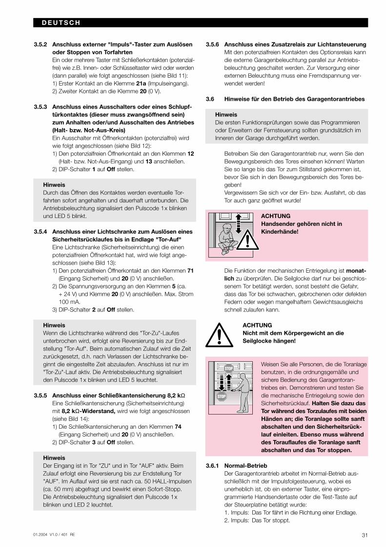
Betreiben Sie den Garagentorantrieb nur, wenn Sie den Bewegungsbereich des Tores einsehen können! Warten Sie so lange bis das Tor zum Stillstand gekommen ist, bevor Sie sich in den Bewegungsbereich des Tores be-geben!Vergewissern Sie sich vor der Ein- bzw. Ausfahrt, ob dasTor auch ganz geöffnet wurde!
ACHTUNGHandsender gehören nicht inKinderhände!
Die Funktion der mechanischen Entriegelung ist monat-lich zu überprüfen. Die Seilglocke darf nur bei geschlos-senem Tor betätigt werden, sonst besteht die Gefahr, dass das Tor bei schwachen, gebrochenen oder defektenFedern oder wegen mangelhaftem Gewichtsausgleichs schnell zulaufen kann.
ACHTUNGNicht mit dem Körpergewicht an dieSeilglocke hängen!
Weisen Sie alle Personen, die die Toranlagebenutzen, in die ordnungsgemäße undsichere Bedienung des Garagentoran-triebes ein. Demonstrieren und testen Siedie mechanische Entriegelung sowie denSicherheitsrücklauf. Halten Sie dazu dasTor während des Torzulaufes mit beidenHänden an; die Toranlage sollte sanftabschalten und den Sicherheitsrück-lauf einleiten. Ebenso muss währenddes Torauflaufes die Toranlage sanftabschalten und das Tor stoppen.
3.6.1 Normal-BetriebDer Garagentorantrieb arbeitet im Normal-Betrieb aus-schließlich mit der Impulsfolgesteuerung, wobei es unerheblich ist, ob ein externer Taster, eine einpro-grammierte Handsendertaste oder die Test-Taste auf der Steuerplatine betätigt wurde:1. Impuls: Das Tor fährt in die Richtung einer Endlage.2. Impuls: Das Tor stoppt.
D E U T S C H
3.5.2 Anschluss externer "Impuls"-Taster zum Auslösen oder Stoppen von TorfahrtenEin oder mehrere Taster mit Schließerkontakten (potenzial-frei) wie z.B. Innen- oder Schlüsseltaster wird oder werden(dann parallel) wie folgt angeschlossen (siehe Bild 11):1) Erster Kontakt an die Klemme 21a (Impulseingang).2) Zweiter Kontakt an die Klemme 20 (0 V).
3.5.3 Anschluss eines Ausschalters oder eines Schlupf-türkontaktes (dieser muss zwangsöffnend sein) zum Anhalten oder/und Ausschalten des Antriebes(Halt- bzw. Not-Aus-Kreis)Ein Ausschalter mit Öffnerkontakten (potenzialfrei) wird wie folgt angeschlossen (siehe Bild 12):1) Den potenzialfreien Öffnerkontakt an den Klemmen 12
(Halt- bzw. Not-Aus-Eingang) und 13 anschließen.2) DIP-Schalter 1 auf Off stellen.
HinweisDurch das Öffnen des Kontaktes werden eventuelle Tor-fahrten sofort angehalten und dauerhaft unterbunden. DieAntriebsbeleuchtung signalisiert den Pulscode 1x blinkenund LED 5 blinkt.
3.5.4 Anschluss einer Lichtschranke zum Auslösen einesSicherheitsrücklaufes bis in Endlage "Tor-Auf"Eine Lichtschranke (Sicherheitseinrichtung) die einenpotenzialfreien Öffnerkontakt hat, wird wie folgt ange-schlossen (siehe Bild 13):1) Den potenzialfreien Öffnerkontakt an den Klemmen 71
(Eingang Sicherheit) und 20 (0 V) anschließen.2) Die Spannungsversorgung an den Klemmen 5 (ca.
+ 24 V) und Klemme 20 (0 V) anschließen. Max. Strom 100 mA.
3) DIP-Schalter 2 auf Off stellen.
HinweisWenn die Lichtschranke während des "Tor-Zu"-Laufesunterbrochen wird, erfolgt eine Reversierung bis zur End-stellung "Tor-Auf". Beim automatischen Zulauf wird die Zeitzurückgesetzt, d.h. nach Verlassen der Lichtschranke be-ginnt die eingestellte Zeit abzulaufen. Anschluss ist nur im"Tor-Zu"-Lauf aktiv. Die Antriebsbeleuchtung signalisiert den Pulscode 1x blinken und LED 5 leuchtet.
3.5.5 Anschluss einer Schließkantensicherung 8,2 kΩEine Schließkantensicherung (Sicherheitseinrichtung) mit 8,2 kΩ-Widerstand, wird wie folgt angeschlossen(siehe Bild 14):1) Die Schließkantensicherung an den Klemmen 74
(Eingang Sicherheit) und 20 (0 V) anschließen.2) DIP-Schalter 3 auf Off stellen.
HinweisDer Eingang ist in Tor "ZU" und in Tor "AUF" aktiv. BeimZulauf erfolgt eine Reversierung bis zur Endstellung Tor"AUF". Im Auflauf wird sie erst nach ca. 50 HALL-Impulsen(ca. 50 mm) abgefragt und bewirkt einen Sofort-Stopp. Die Antriebsbeleuchtung signalisiert den Pulscode 1x blinken und LED 2 leuchtet.
01.2004 V1.0 / 401 RE32
D E U T S C H
Hinweis: Wenn keine Lichtschranke an den Klemmen 20 und 71 angeschlossen ist, überprüfen, ob DIP-Schalter 2 auf "ON" steht.
Beleuchtung: blinkt 1 x in 1 SekundeLED: 2 leuchtet
Ursache: Eine an die Klemmen 20 und 74 angeschlos-sene Schließkantensicherung wurde unter-brochen oder betätigt (siehe Kapitel 3.5.5).
Behebung: Das auslösende Hindernis beseitigen und/ oder die Schließkantensicherung überprüfen, gegebenenfalls auswechseln.
Hinweis: Wenn keine Schließkantensicherung an den Klemmen 20 und 74 angeschlossen ist, über-prüfen, ob DIP-Schalter 3 auf "ON" steht und an den Klemmen 20 und 74 nichts angeschlos-sen ist.
Beleuchtung: blinkt 2 x in 3 Sekunden
Ursache: Der Antrieb hat aufgrund der Sicherheitskon-taktleiste oder Überstromabschaltung zweimalbis zur Endstellung Tor "AUF" reversiert.
Behebung: Das auslösende Hindernis beseitigen und/oderdie Schließkantensicherung überprüfen, gege-benenfalls auswechseln. Torlauf überprüfen und ggf. den Einlernvorgang durchführen (siehe Kapitel 3.3.2).
Quittierung: Erneute Impulsgabe durch einen externen Taster, den Funkempfänger oder den Platinen-Taster.
Hinweis: Diese Fehleranzeige wird nur bei eingestelltem Automatischen Zulauf angezeigt.
Beleuchtung: blinkt 3 x in 4 Sekunden
Ursache: Der Antrieb ist noch nicht eingelernt (dieses ist nur ein Hinweis und kein Fehler).
Behebung: Den Einlernvorgang durchführen (siehe Kapitel 3.3.2).
Beleuchtung: blinkt 4 x in 5 Sekunden
Ursache: siehe Kapitel 3.6.4Behebung: siehe Kapitel 3.6.4
Beleuchtung: blinkt 5 x in 6 Sekunden
Ursache: Die Programmierung des Automatischen Zulaufs wurde gestartet (dieses ist nur ein Hinweis und kein Fehler).
Behebung: Den Programmiervorgang durchführen (siehe Kapitel 3.4).
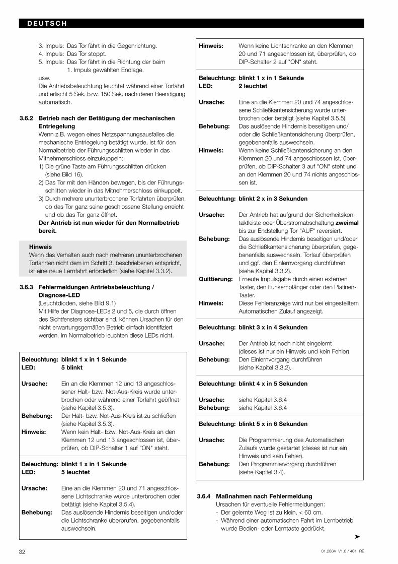
3.6.4 Maßnahmen nach FehlermeldungUrsachen für eventuelle Fehlermeldungen:- Der gelernte Weg ist zu klein, < 60 cm.- Während einer automatischen Fahrt im Lernbetrieb
wurde Bedien- oder Lerntaste gedrückt.
3. Impuls: Das Tor fährt in die Gegenrichtung.4. Impuls: Das Tor stoppt.5. Impuls: Das Tor fährt in die Richtung der beim
1. Impuls gewählten Endlage.usw.Die Antriebsbeleuchtung leuchtet während einer Torfahrtund erlischt 5 Sek. bzw. 150 Sek. nach deren Beendigungautomatisch.
3.6.2 Betrieb nach der Betätigung der mechanischen EntriegelungWenn z.B. wegen eines Netzspannungsausfalles die mechanische Entriegelung betätigt wurde, ist für den Normalbetrieb der Führungsschlitten wieder in das Mitnehmerschloss einzukuppeln:1) Die grüne Taste am Führungsschlitten drücken
(siehe Bild 16).2) Das Tor mit den Händen bewegen, bis der Führungs-
schlitten wieder in das Mitnehmerschloss einkuppelt.3) Durch mehrere ununterbrochene Torfahrten überprüfen,
ob das Tor ganz seine geschlossene Stellung erreicht und ob das Tor ganz öffnet.
Der Antrieb ist nun wieder für den Normalbetrieb bereit.
HinweisWenn das Verhalten auch nach mehreren ununterbrochenenTorfahrten nicht dem im Schritt 3. beschriebenen entspricht,ist eine neue Lernfahrt erforderlich (siehe Kapitel 3.3.2).
3.6.3 Fehlermeldungen Antriebsbeleuchtung / Diagnose-LED(Leuchtdioden, siehe Bild 9.1)Mit Hilfe der Diagnose-LEDs 2 und 5, die durch öffnendes Sichtfensters sichtbar sind, können Ursachen für dennicht erwartungsgemäßen Betrieb einfach identifiziert werden. Im Normalbetrieb leuchten diese LEDs nicht.
Beleuchtung: blinkt 1 x in 1 SekundeLED: 5 blinkt
Ursache: Ein an die Klemmen 12 und 13 angeschlos-sener Halt- bzw. Not-Aus-Kreis wurde unter-brochen oder während einer Torfahrt geöffnet (siehe Kapitel 3.5.3).
Behebung: Der Halt- bzw. Not-Aus-Kreis ist zu schließen(siehe Kapitel 3.5.3).
Hinweis: Wenn kein Halt- bzw. Not-Aus-Kreis an den Klemmen 12 und 13 angeschlossen ist, über-prüfen, ob DIP-Schalter 1 auf "ON" steht.
Beleuchtung: blinkt 1 x in 1 SekundeLED: 5 leuchtet
Ursache: Eine an die Klemmen 20 und 71 angeschlos-sene Lichtschranke wurde unterbrochen oder betätigt (siehe Kapitel 3.5.4).
Behebung: Das auslösende Hindernis beseitigen und/oder die Lichtschranke überprüfen, gegebenenfalls auswechseln.
01.2004 V1.0 / 401 RE 33
- Während einer automatischen Fahrt im Lernbetrieb wurde der Schlupftürkontakt / Lichtschrankeneingangoder die Sicherheitsleiste aktiviert.
- Nach dem Start des Lernvorgangs wurde 60 Sekundenlang keine Taste betätigt.
- Der Hallsensor ist defekt.
3.7 Störung und AbhilfeSollte Ihr Garagentoröffner einmal nicht funktionieren,überprüfen Sie bitte die Anlage nach folgendenGesichtspunkten:
ACHTUNGVor Arbeiten am Gerät mit entfernterHaube unbedingt den Netzstecker ziehen!
3.7.1 Antrieb läuft nicht:Prüfen, ob Netzspannung anliegt.
3.7.2 Antrieb läuft nicht mit Handsender:Wenn bei gedrückter Sendertaste die LED-Kontroll-leuchte nicht aufleuchtet, ist die Batteriespannung zuniedrig. Batterie im Handsender erneuern. Wenn trotzBatteriewechsels die Anlage nicht funktioniert, Hand-sender bzw. Empfänger überprüfen.
3.7.3 Antrieb läuft nicht mit extern angeschlossenenTastern:Taster, Zuleitungen und Anschlussklemmen überprüfen.
ACHTUNGKein Dauersignal und keineFremdspannung zulässig.
3.7.4 Tor schließt oder öffnet nicht vollständig:Tormechanik klemmt.Ein Hindernis versperrt den Laufweg.Torlauf korrigieren bzw. Hindernis entfernen.Antrieb neu einlernen! Siehe Punkt 3.3.2
3.7.5 Der Antrieb reagiert, jedoch öffnet sich das Tornicht:Torverriegelungen überprüfen, ggf. entfernen.Transportschlitten ist nicht am Mitnehmer eingerastet.Notentriegelung überprüfen.
3.7.6 Tor kehrt bei Zu - Bewegung seine Laufrichtung um:Tormechanik klemmt.Ein Hindernis versperrt den Laufweg.Torlauf korrigieren bzw. Hindernis entfernen.Neu einlernen gemäß Punkt 3.3.2
3.7.7 Beleuchtung defekt:Netzstecker ziehen.Sichtfenster entfernen.Prüfen, ob Halogenlampe fest eingesteckt ist.Halogenlampe austauschen (G 4 / 20 W, klar).
3.7.8 Reichweite der Funkfernsteuerung zu gering:Batterie des Handsenders überprüfen.Antennenverlegung korrigieren.
4 Garantiebedingungen
Dauer der GarantieZusätzlich zur gesetzlichen Gewährleistung des Händlersaus dem Kaufvertrag leisten wir Garantie für die Dauer von 24 Monaten ab Kaufdatum. Durch die Inanspruch-nahme der Garantie verlängert sich die Garantie nicht. Für Ersatzlieferungen und Nachbesserungsarbeiten be-trägt die Gewährleistungsfrist sechs Monate, mindestensaber die anfängliche Gewährleistungsfrist.
VoraussetzungenDer Garantieanspruch gilt nur für das Land, in dem das Gerät gekauft wurde. Die Ware muss auf dem von uns vorgegebenen Vertriebsweg erstanden worden sein. DerGarantieanspruch besteht nur für Schäden am Vertrags-gegenstand selbst. Die Erstattung von Aufwendungen für Aus- und Einbau, Überprüfung entsprechender Teile so-wie Forderungen nach entgangenem Gewinn und Scha-denersatz sind von der Gewährleistung ausgeschlossen.Der Kaufbeleg gilt als Nachweis für Ihren Garantiean-spruch.
LeistungFür die Dauer der Garantie beseitigen wir alle Mängel am Produkt, die nachweislich auf einen Material- oder Herstellungsfehler zurückzuführen sind. Wir verpflichten uns, nach unserer Wahl die mangelhafte Ware unent-geltlich gegen mangelfreie zu ersetzen, nachzubessern oder einen Minderwert zu ersetzen.
D E U T S C H
Dauerlicht
4 Pulse = Fehler
3 Pulse = Keine gültigenWerte im Speicher
weiße Tastekurz drücken
Schlitten musseingerastet sein
Schlitten musseingerastet sein
Tor fährt langsam in"Tor-Zu"-Position.
Synchronisierlauf ohneKraftüberwachung.
2 Pulse = Lernpulsesiehe 3.3.2
Antrieb betriebsbereit
INI-Taste(schwarz)
6 Sek. drücken
Antrieb betriebsbereit
weiße Tastekurz drücken
01.2004 V1.0 / 401 RE34
D E U T S C H
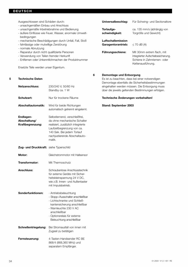
Ausgeschlossen sind Schäden durch:- unsachgemäßen Einbau und Anschluss- unsachgemäße Inbetriebnahme und Bedienung- äußere Einflüsse wie Feuer, Wasser, anormale Umwelt-
bedingungen - mechanische Beschädigungen durch Unfall, Fall, Stoß- fahrlässige oder mutwillige Zerstörung - normale Abnutzung- Reparatur durch nicht qualifizierte Personen- Verwendung von Teilen fremder Herkunft- Entfernen oder Unkenntlichmachen der Produktnummer
Ersetzte Teile werden unser Eigentum.
5 Technische Daten
Netzanschluss: 230/240 V, 50/60 HzStandby ca. 1 W
Schutzart: Nur für trockene Räume
Abschaltautomatik: Wird für beide Richtungen automatisch getrennt eingelernt.
Endlagen- Selbstlernend, verschleißfrei,Abschaltung/ da ohne mechanische SchalterKraftbegrenzung: realisiert, zusätzlich integrierte
Laufzeitbegrenzung von ca. 140 Sek. Bei jedem Torlauf nachjustierende Abschaltauto-matik.
Zug- und Druckkraft: siehe Typenschild
Motor: Gleichstrommotor mit Hallsensor
Transformator: Mit Thermoschutz
Anschluss: Schraubenlose Anschlusstechnikfür externe Geräte mit Sicher-heitskleinspannung 24 V DC, wie z.B. Innen- und Außentastermit Impulsbetrieb.
Sonderfunktionen: - Antriebsbeleuchtung- Stopp-/Ausschalter anschließbar- Lichtschranke und Schließ-
kantensicherung anschließbar- Warnleuchte 230 V AC
anschließbar- Optionsrelais für externe
Beleuchtung anschließbar
Schnellentriegelung: Bei Stromausfall von innen mit Zugseil zu betätigen
Fernsteuerung: 4-Tasten-Handsender RC BE 868/4 (868,360 MHz) und separatem Empfänger.
Universalbeschlag: Für Schwing- und Sectionaltore
Torlaufge- ca. 135 mm/s (abhängig vonschwindigkeit: Torgröße und Gewicht)
LuftschallemissionGaragentorantrieb: ≤ 70 dB (A)
Führungsschiene: Mit 30mm extrem flach, mitintegrierter Aufschiebesicherung.Schiene in Zahnriemen- oder Kettenausführung.
6 Demontage und EntsorgungEs ist zu beachten, dass bei einer notwendigenDemontage ebenfalls die Sicherheitsbestimmungen eingehalten werden müssen. Die Entsorgung muss über die jeweils geltenden Bestimmungen erfolgen.
Technische Änderungen vorbehalten!
Stand: September 2003
01.2004 V1.0 / 401 RE 35
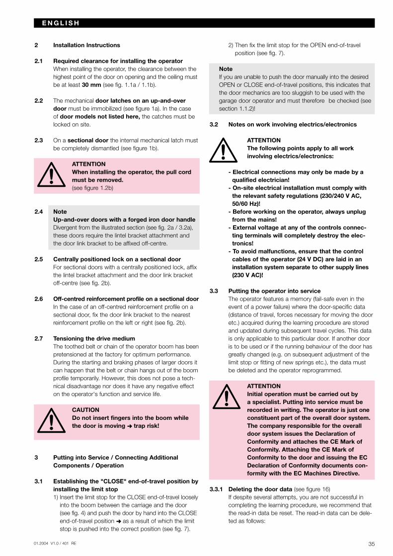
2 Installation Instructions
2.1 Required clearance for installing the operatorWhen installing the operator, the clearance between thehighest point of the door on opening and the ceiling mustbe at least 30 mm (see fig. 1.1a / 1.1b).
2.2 The mechanical door latches on an up-and-overdoor must be immobilized (see figure 1a). In the case of door models not listed here, the catches must belocked on site.
2.3 On a sectional door the internal mechanical latch mustbe completely dismantled (see figure 1b).
ATTENTIONWhen installing the operator, the pull cordmust be removed.(see figure 1.2b)
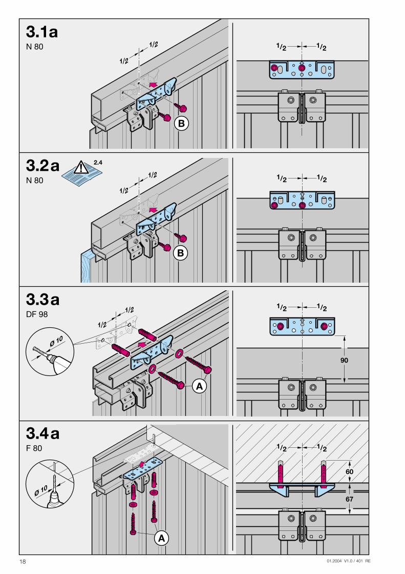
2.4 NoteUp-and-over doors with a forged iron door handleDivergent from the illustrated section (see fig. 2a / 3.2a),these doors require the lintel bracket attachment andthe door link bracket to be affixed off-centre.
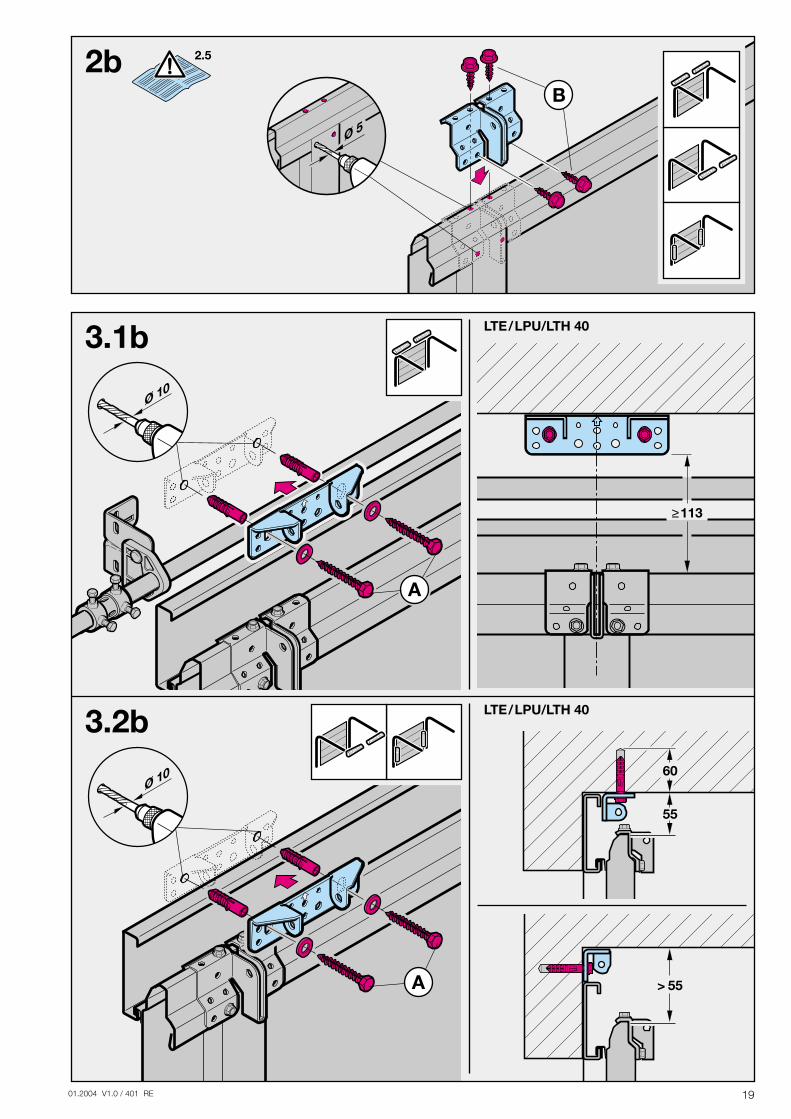
2.5 Centrally positioned lock on a sectional doorFor sectional doors with a centrally positioned lock, affixthe lintel bracket attachment and the door link bracketoff-centre (see fig. 2b).
2.6 Off-centred reinforcement profile on a sectional doorIn the case of an off-centred reinforcement profile on asectional door, fix the door link bracket to the nearestreinforcement profile on the left or right (see fig. 2b).
2.7 Tensioning the drive mediumThe toothed belt or chain of the operator boom has beenpretensioned at the factory for optimum performance.During the starting and braking phases of larger doors itcan happen that the belt or chain hangs out of the boomprofile temporarily. However, this does not pose a tech-nical disadvantage nor does it have any negative effecton the operator's function and service life.
CAUTIONDo not insert fingers into the boom whilethe door is moving trap risk!
3 Putting into Service / Connecting AdditionalComponents / Operation
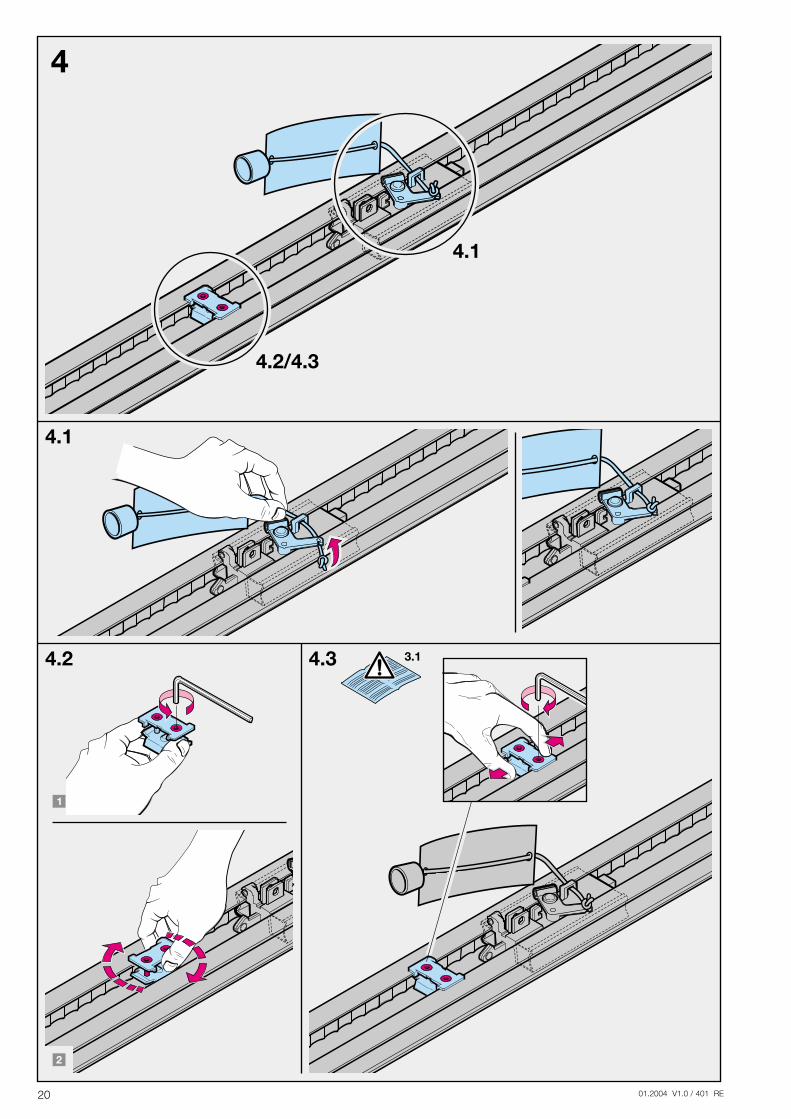
3.1 Establishing the "CLOSE" end-of-travel position byinstalling the limit stop1) Insert the limit stop for the CLOSE end-of-travel loosely
into the boom between the carriage and the door(see fig. 4) and push the door by hand into the CLOSEend-of-travel position as a result of which the limitstop is pushed into the correct position (see fig. 7).
2) Then fix the limit stop for the OPEN end-of-travelposition (see fig. 7).
NoteIf you are unable to push the door manually into the desiredOPEN or CLOSE end-of-travel positions, this indicates thatthe door mechanics are too sluggish to be used with thegarage door operator and must therefore be checked (seesection 1.1.2)!
3.2 Notes on work involving electrics/electronics
ATTENTION The following points apply to all work involving electrics/electronics:
- Electrical connections may only be made by aqualified electrician!
- On-site electrical installation must comply withthe relevant safety regulations (230/240 V AC,50/60 Hz)!
- Before working on the operator, always unplugfrom the mains!
- External voltage at any of the controls connec-ting terminals will completely destroy the elec-tronics!
- To avoid malfunctions, ensure that the controlcables of the operator (24 V DC) are laid in aninstallation system separate to other supply lines(230 V AC)!
3.3 Putting the operator into serviceThe operator features a memory (fail-safe even in theevent of a power failure) where the door-specific data(distance of travel, forces necessary for moving the dooretc.) acquired during the learning procedure are storedand updated during subsequent travel cycles. This datais only applicable to this particular door. If another dooris to be used or if the running behaviour of the door hasgreatly changed (e.g. on subsequent adjustment of thelimit stop or fitting of new springs etc.), the data mustbe deleted and the operator reprogrammed.
ATTENTION Initial operation must be carried out by a specialist. Putting into service must berecorded in writing. The operator is just oneconstituent part of the overall door system.The company responsible for the overalldoor system issues the Declaration ofConformity and attaches the CE Mark ofConformity. Attaching the CE Mark ofConformity to the door and issuing the ECDeclaration of Conformity documents con-formity with the EC Machines Directive.
3.3.1 Deleting the door data (see figure 16)If despite several attempts, you are not successful incompleting the learning procedure, we recommend thatthe read-in data be reset. The read-in data can be dele-ted as follows:
E N G L I S H
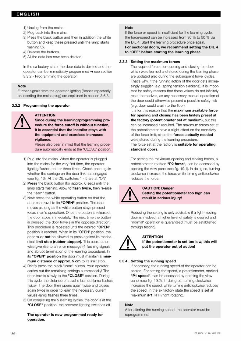
1) Unplug from the mains.2) Plug back into the mains.3) Press the black button and then in addition the white
button and keep these pressed until the lamp startsflashing 3x.
4) Release the buttons.5) All the data has now been deleted.
In the ex factory state, the door data is deleted and theoperator can be immediately programmed see section3.3.2 - Programming the operator
NoteFurther signals from the operator lighting (flashes repeatedlyon inserting the mains plug) are explained in section 3.6.3.
3.3.2 Programming the operator
ATTENTIONSince during the learning/programming pro-cedure the force cutoff is without function,it is essential that the installer stays with the equipment and exercises increased vigilance.Please also bear in mind that the learning proce-dure automatically ends at the "CLOSE" position.
1) Plug into the mains. When the operator is pluggedinto the mains for the very first time, the operatorlighting flashes one or three times. Check once againwhether the carriage on the door link has engaged(see fig. 16). All the DIL switches 1 - 5 are at "ON".
2) Press the black button (for approx. 6 sec.) until thelamp starts flashing. Allow to flash twice, then releasethe "learn" button.
3) Now press the white operating button so that thedoor can travel to its "OPEN" position. The doormoves as long as the white button stays pressed(dead man's operation). Once the button is released,the door stops immediately. The next time the buttonis pressed, the door travels in the opposite direction.This procedure is repeated until the desired "OPEN"position is reached. When in its "OPEN" position, thedoor must not be allowed to press against its mecha-nical limit stop (rubber stopper). This could other-wise give rise to an error message (4 flashing signalsand abrupt termination of the learning procedure). Inits "OPEN" position the door must maintain a mini-mum distance of approx. 5 cm to its limit stop.
4) Briefly press the black "learn" button. Your operatorcarries out the remaining settings automatically! Thedoor travels slowly to the "CLOSE" position. Duringthis cycle, the distance of travel is learned (lamp flashestwice). The door then opens again twice and closesagain twice in order to learn the necessary currentvalues (lamp flashes three times).
5) On completing the 5 learning cycles, the door is at the"CLOSE" position, the operator lighting switches off.
The operator is now programmed ready for operation.
NoteIf the force or speed is insufficient for the learning cycle, the force/speed can be increased from 30 % to 50 % viathe DIL 4. Start the learning procedure once again.For sectional doors, we recommend setting the DIL 4to "OFF" before starting the learning phase.
3.3.3 Setting the maximum forces The required forces for opening and closing the door,which were learned and stored during the learning phase,are updated also during the subsequent travel cycles.That's why, if the running action of the door gets increa-singly sluggish (e.g. spring tension slackens), it is impor-tant for safety reasons that these values do not infinitelyreset themselves, as any necessary manual operation ofthe door could otherwise present a possible safety risk(e.g. door could crash to the floor). It is for this reason that the maximum available forcefor opening and closing has been finitely preset atthe factory (potentiometer set at medium), but thiscan be increased if required. The maximum forces set atthe potentiometer have a slight effect on the sensitivityof the force limit, since the forces actually neededwere stored during the learning procedure.The force set at the factory is suitable for operatingstandard doors.
For setting the maximum opening and closing forces, apotentiometer, marked "P2 force", can be accessed byopening the view panel (see fig. 19.1). In doing so, turningclockwise increases the force, while turning anticlockwisereduces the force.
CAUTION: DangerSetting the potentiometer too high canresult in serious injury!
Reducing the setting is only advisable if a light-movingdoor is involved, a higher level of safety is desired and"normal" operation is guaranteed (must be establishedthrough testing).
ATTENTION If the potentiometer is set too low, this willput the operator out of action!
3.3.4 Setting the running speedIf necessary, the running speed of the operator can bealtered. For setting the speed, a potentiometer, marked"P1 speed", can be accessed by opening the viewpanel (see fig. 19.2). In doing so, turning clockwiseincreases the speed, while turning anticlockwise reducesthe speed. In the ex factory state the speed is set atmaximum (P1 RHH/right rotating).
NoteAfter altering the running speed, the operator must bereprogrammed!
36 01.2004 V1.0 / 401 RE
E N G L I S H
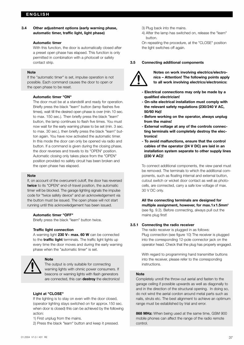
3701.2004 V1.0 / 401 RE
3.4 Other adjustment options (early warning phase,automatic timer, traffic light, light phase)
Automatic timer With this function, the door is automatically closed aftera preset open phase has elapsed. This function is onlypermitted in combination with a photocell or safetycontact strip.
NoteIf the "automatic timer" is set, impulse operation is not possible. Each command causes the door to open or the open phase to be reset.
Automatic timer "ON"The door must be at a standstill and ready for operation.Briefly press the black "learn" button (lamp flashes fivetimes), wait till the desired open phase is over (min.10 sec.to max. 150 sec.). Then briefly press the black "learn"button, the lamp continues to flash five times. You mustnow wait for the early warning phase to be set (min. 3 sec.to max. 30 sec.), then briefly press the black "learn" but-ton again. You have now activated the automatic timer.In this mode the door can only be opened via radio andbutton. If a command is given during the closing phase,the door reverses and travels to its "OPEN" position.Automatic closing only takes place from the "OPEN"position provided no safety circuit has been broken andthe open phase has elapsed.
NoteIf, on account of the overcurrent cutoff, the door has reversedtwice to its "OPEN" end-of-travel position, the automatictimer will be blocked. The garage lighting signals the impulsecode for "twice safety device" and an acknowledgement viathe button must be issued. The open phase will not startrunning until this acknowledgement has been issued.
Automatic timer "OFF"Briefly press the black "learn" button twice.
Traffic light connectionA warning light 230 V~ max. 60 W can be connected to the traffic light terminals. The traffic light lights upevery time the door moves and during the early warningphase when the "automatic timer" is set.
NoteThe output is only suitable for connecting warning lights with ohmic power consumers. Ifbeacons or warning lights with flash generatorsare connected, this can destroy the electronics!
Light at "CLOSE"If the lighting is to stay on even with the door closed,(operator lighting stays switched on for approx.150 sec.when door is closed) this can be achieved by the followingaction:1) First unplug from the mains.2) Press the black "learn" button and keep it pressed.
3) Plug back into the mains.4) After the lamp has switched on, release the "learn"
button.On repeating the procedure, at the "CLOSE" positionthe light switches off again.
3.5 Connecting additional components
Notes on work involving electrics/electro-nics – Attention! The following points applyto all work involving electrics/electronics:
- Electrical connections may only be made by aqualified electrician!
- On-site electrical installation must comply withthe relevant safety regulations (230/240 V AC,50/60 Hz)!
- Before working on the operator, always unplugfrom the mains!
- External voltage at any of the controls connec-ting terminals will completely destroy the elec-tronics!
- To avoid malfunctions, ensure that the controlcables of the operator (24 V DC) are laid in aninstallation system separate to other supply lines(230 V AC)!
To connect additional components, the view panel mustbe removed. The terminals to which the additional com-ponents, such as floating internal and external button,cutout switch or wicket door contact as well as photo-cells, are connected, carry a safe low voltage of max. 30 V DC only.
All the connecting terminals are designed for multiple assignment, however, for max.1x1.5mm2
(see fig. 9.2). Before connecting, always pull out themains plug first!
3.5.1 Connecting the radio receiverThe radio receiver is plugged in as follows:Plug connection (see figure 10) The receiver is pluggedinto the corresponding 12-pole connector jack on theoperator head. Check that the plug has properly engaged.
With regard to programming hand transmitter buttonsinto the receiver, please refer to the correspondinginstructions.
NoteCompletely unroll the throw-out aerial and fasten to thegarage ceiling if possible upwards as well as diagonally toand in the direction of the structural opening. In doing so,do not wind the aerial cordon around metal parts such asnails, struts etc. The best alignment to achieve an optimumrange must be established by trial and error.
868 MHz: When being used at the same time, GSM 900mobile phones can affect the range of the radio remotecontrol.
E N G L I S H
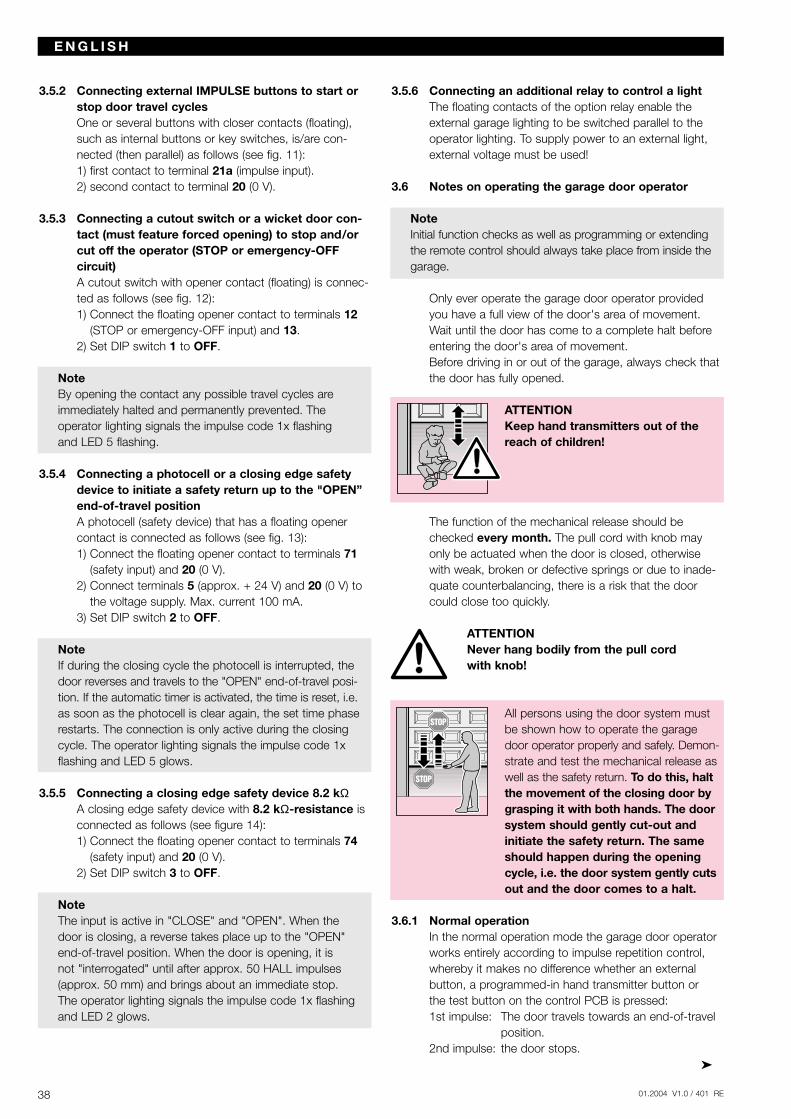
3.5.2 Connecting external IMPULSE buttons to start orstop door travel cyclesOne or several buttons with closer contacts (floating),such as internal buttons or key switches, is/are con-nected (then parallel) as follows (see fig. 11):1) first contact to terminal 21a (impulse input).2) second contact to terminal 20 (0 V).
3.5.3 Connecting a cutout switch or a wicket door con-tact (must feature forced opening) to stop and/orcut off the operator (STOP or emergency-OFF circuit)A cutout switch with opener contact (floating) is connec-ted as follows (see fig. 12):1) Connect the floating opener contact to terminals 12
(STOP or emergency-OFF input) and 13.2) Set DIP switch 1 to OFF.
NoteBy opening the contact any possible travel cycles are immediately halted and permanently prevented. The operator lighting signals the impulse code 1x flashing and LED 5 flashing.
3.5.4 Connecting a photocell or a closing edge safetydevice to initiate a safety return up to the "OPEN”end-of-travel positionA photocell (safety device) that has a floating openercontact is connected as follows (see fig. 13):1) Connect the floating opener contact to terminals 71
(safety input) and 20 (0 V). 2) Connect terminals 5 (approx. + 24 V) and 20 (0 V) to
the voltage supply. Max. current 100 mA.3) Set DIP switch 2 to OFF.
NoteIf during the closing cycle the photocell is interrupted, thedoor reverses and travels to the "OPEN" end-of-travel posi-tion. If the automatic timer is activated, the time is reset, i.e.as soon as the photocell is clear again, the set time phaserestarts. The connection is only active during the closingcycle. The operator lighting signals the impulse code 1xflashing and LED 5 glows.
3.5.5 Connecting a closing edge safety device 8.2 kΩA closing edge safety device with 8.2 kΩ-resistance isconnected as follows (see figure 14):1) Connect the floating opener contact to terminals 74
(safety input) and 20 (0 V).2) Set DIP switch 3 to OFF.
NoteThe input is active in "CLOSE" and "OPEN". When the door is closing, a reverse takes place up to the "OPEN"end-of-travel position. When the door is opening, it is not "interrogated" until after approx. 50 HALL impulses(approx. 50 mm) and brings about an immediate stop. The operator lighting signals the impulse code 1x flashingand LED 2 glows.
3.5.6 Connecting an additional relay to control a light The floating contacts of the option relay enable theexternal garage lighting to be switched parallel to theoperator lighting. To supply power to an external light,external voltage must be used!
3.6 Notes on operating the garage door operator
NoteInitial function checks as well as programming or extendingthe remote control should always take place from inside thegarage.
Only ever operate the garage door operator providedyou have a full view of the door's area of movement.Wait until the door has come to a complete halt beforeentering the door's area of movement.Before driving in or out of the garage, always check thatthe door has fully opened.
ATTENTION Keep hand transmitters out of thereach of children!
The function of the mechanical release should bechecked every month. The pull cord with knob mayonly be actuated when the door is closed, otherwisewith weak, broken or defective springs or due to inade-quate counterbalancing, there is a risk that the doorcould close too quickly.
ATTENTION Never hang bodily from the pull cord with knob!
All persons using the door system mustbe shown how to operate the garagedoor operator properly and safely. Demon-strate and test the mechanical release aswell as the safety return. To do this, haltthe movement of the closing door bygrasping it with both hands. The doorsystem should gently cut-out andinitiate the safety return. The sameshould happen during the openingcycle, i.e. the door system gently cutsout and the door comes to a halt.
3.6.1 Normal operationIn the normal operation mode the garage door operatorworks entirely according to impulse repetition control,whereby it makes no difference whether an external button, a programmed-in hand transmitter button or the test button on the control PCB is pressed:1st impulse: The door travels towards an end-of-travel
position.2nd impulse: the door stops.
38 01.2004 V1.0 / 401 RE
E N G L I S H
3901.2004 V1.0 / 401 RE
3rd impulse: the door travels in the opposite direction.4th impulse: the door stops.5th impulse: the door travels in the direction of the
end-of-travel position selected with the 1st impulse.
etc.The operator lighting comes on when the door starts tomove and automatically goes out 5 or 150 sec. later oncompletion of the cycle.
3.6.2 Operation following actuation of the mechanical/manual releaseIf, for instance due to a mains power failure, the mecha-nical release was actuated, the carriage must reengagein the door link latch before normal operation can beresumed:1) Press the large button on the carriage (see figure 16).2) Move the door manually until the carriage reengages
in the door link latch.3) Allow the door to complete several uninterrupted
opening and closing cycles to check whether it hasfully closed and fully opened.
The operator is now ready again to resume normaloperation.
NoteIf, after carrying out several interrupted door cycles, the behaviour of the door does not correspond to thatdescribed in stage 3, it will be necessary to rerun the learning procedure (see section 3.3.2).
3.6.3 Operator lighting / diagnostic LED error messages(LEDs, see fig. 9.1)Aided by the diagnostic LEDs 2 and 5, which becomevisible on opening the view window, causes for abnormaloperation are easy to identify. When operation is normal,these LEDs do not glow.
Lighting: flashes 1 x in 1 secondLED: 5 flashes
Cause: A STOP or emergency-OFF circuit at terminals 12 and 13 has been broken or during a travel cycle opened (see section 3.5.3).
Remedy: Close the STOP or emergency-OFF circuit (see section 3.5.3)
Note: If a STOP or emergency-OFF circuit is not connected to terminals 12 and 13, check whether the DIP switch 1 is set at "ON".
Lighting: flashes 1 x in 1 secondLED: 5 glows
Cause: A photocell connected to terminals 20 and 71 has been interrupted or activated (see section 3.5.4).
Remedy: Remove the obstruction causing the problem and/or check the photocell, and if necessary replace.
Note: If a STOP or emergency-OFF circuit is not connected to terminals 20 and 71, check whether the DIP switch 2 is set at "ON"
Lighting: flashes 1 x in 1 secondLED: 2 glows
Cause: A photocell connected to terminals 20 and 74 has been interrupted or activated (see section 3.5.5).
Remedy: Remove the obstruction causing the problem and/or check the photocell, and if necessary replace.
Note: If no closing edge safety device is connected to the terminals 20 and 74, check whether DIPswitch 3 is at "ON" and nothing is connected to terminals 20 and 74.
Lighting: flashes 2 x in 3 seconds
Cause: Due to an overcurrent cutoff, the operator has reversed twice to the "OPEN" end-of-travel position.
Remedy: Remove the obstruction causing the problem and/or check the photocell, and if necessary replace. Check the door action and, if neces-sary, run through the learning procedure (see section 3.3.2).
Acknow-ledgement: Generate another impulse via an external
button, the radio receiver or the PCB button.Note: This error is only displayed if the automatic
timer is set.
Lighting: flashes 3 x in 4 seconds
Cause: Operator has not yet undergone the learning procedure (this is simply being brought to your attention, it does not constitute an error).
Remedy: Run through the learning procedure (section 3.3.2).
Lighting: flashes 4 x in 5 seconds
Cause: see section 3.6.4Remedy: see section 3.6.4
Lighting: flashes 5 x in 6 seconds
Cause: Programming of the automatic timer has been started (this is simply being brought to your attention, it does not constitute an error).
Remedy: Run through the learning procedure(see section 3.4).
3.6.4 Measures following error message Causes of possible error messages:- The learned distance is too short, < 60 cm.- During an automatic travel cycle when running through
the learning procedure, the operating or "learn" buttonwas pressed.
E N G L I S H
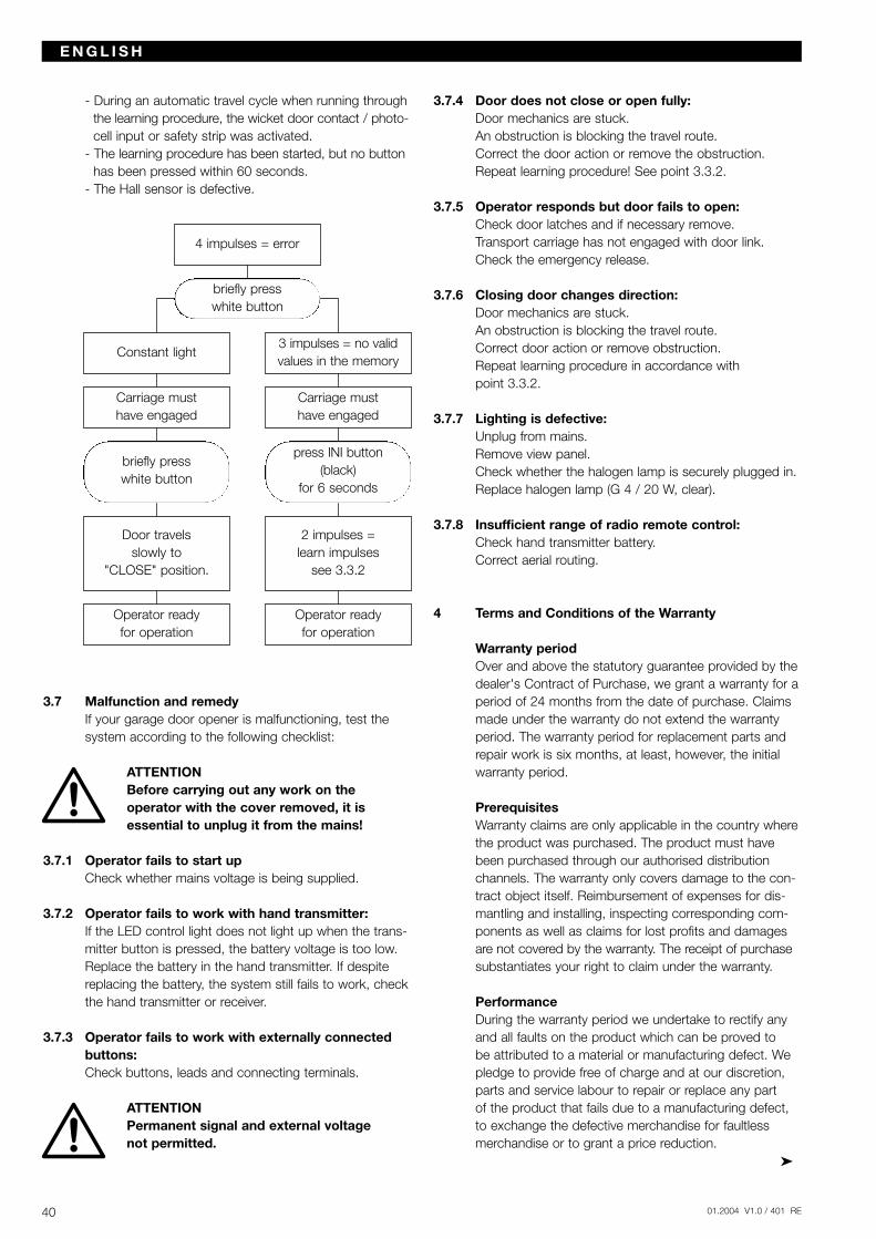
- During an automatic travel cycle when running throughthe learning procedure, the wicket door contact / photo-cell input or safety strip was activated.
- The learning procedure has been started, but no buttonhas been pressed within 60 seconds.
- The Hall sensor is defective.
3.7 Malfunction and remedyIf your garage door opener is malfunctioning, test thesystem according to the following checklist:
ATTENTION Before carrying out any work on the operator with the cover removed, it isessential to unplug it from the mains!
3.7.1 Operator fails to start upCheck whether mains voltage is being supplied.
3.7.2 Operator fails to work with hand transmitter:If the LED control light does not light up when the trans-mitter button is pressed, the battery voltage is too low.Replace the battery in the hand transmitter. If despitereplacing the battery, the system still fails to work, checkthe hand transmitter or receiver.
3.7.3 Operator fails to work with externally connectedbuttons:Check buttons, leads and connecting terminals.
ATTENTION Permanent signal and external voltage not permitted.
3.7.4 Door does not close or open fully:Door mechanics are stuck.An obstruction is blocking the travel route.Correct the door action or remove the obstruction.Repeat learning procedure! See point 3.3.2.
3.7.5 Operator responds but door fails to open:Check door latches and if necessary remove.Transport carriage has not engaged with door link.Check the emergency release.
3.7.6 Closing door changes direction:Door mechanics are stuck.An obstruction is blocking the travel route.Correct door action or remove obstruction.Repeat learning procedure in accordance with point 3.3.2.
3.7.7 Lighting is defective:Unplug from mains.Remove view panel.Check whether the halogen lamp is securely plugged in.Replace halogen lamp (G 4 / 20 W, clear).
3.7.8 Insufficient range of radio remote control:Check hand transmitter battery.Correct aerial routing.
4 Terms and Conditions of the Warranty
Warranty periodOver and above the statutory guarantee provided by thedealer's Contract of Purchase, we grant a warranty for aperiod of 24 months from the date of purchase. Claimsmade under the warranty do not extend the warrantyperiod. The warranty period for replacement parts andrepair work is six months, at least, however, the initialwarranty period.
PrerequisitesWarranty claims are only applicable in the country wherethe product was purchased. The product must havebeen purchased through our authorised distributionchannels. The warranty only covers damage to the con-tract object itself. Reimbursement of expenses for dis-mantling and installing, inspecting corresponding com-ponents as well as claims for lost profits and damagesare not covered by the warranty. The receipt of purchasesubstantiates your right to claim under the warranty.
PerformanceDuring the warranty period we undertake to rectify anyand all faults on the product which can be proved to be attributed to a material or manufacturing defect. Wepledge to provide free of charge and at our discretion,parts and service labour to repair or replace any part of the product that fails due to a manufacturing defect,to exchange the defective merchandise for faultlessmerchandise or to grant a price reduction.
40 01.2004 V1.0 / 401 RE
E N G L I S H
Constant light
4 impulses = error
3 impulses = no validvalues in the memory
briefly presswhite button
Carriage must have engaged
Carriage must have engaged
Door travels slowly to
"CLOSE" position.
2 impulses = learn impulses
see 3.3.2
Operator ready for operation
press INI button(black)
for 6 seconds
Operator ready for operation
briefly presswhite button
4101.2004 V1.0 / 401 RE
The warranty does not cover damage caused as a result of: - improper installation and connection- improper use, putting into service and operation- external influences, such as fire, water, abnormal
environmental conditions - mechanical damage as a result of an accident,
a fall or impact- negligent or wanton destruction- normal wear and tear- repairs carried out by non-qualified persons- using parts of another manufacturer- removing the product number or making it
unidentifiable
Replaced parts become our property.
5 Technical Data
Power supply: 230/240 V, 50/60 HzStandby approx. 1 W
Protection category: For dry rooms only
Automatic cutout: Is automatically programmed separately for both operational directions.
End-of-travel Self-learning, non-wearing,cutoff / Force limit: since no mechanical switches
are used, additionally integratedexcess travel stop of approx. 140 s. Automatic cutout read-justs itself during each door cycle.
Push and pull force: see type plate
Motor: DC motor with Hall sensor
Transformer: with thermal overload protection
Connection: Connection technique without screws for external equipment with safe low voltage of 24 V DC,e.g. internal and external but-tons for impulse control.
Special functions: - Operator lighting- STOP/cutout switch can be
connected- Photocell and closing edge
safety device can be con-nected
- Warning light 230 V AC can be connected
- Options relay for connecting an external light
Quick release: In the event of a power failure, actuated from the inside via a pull cord
Remote control: 4-button hand transmitter RC BE 868/4 (868.360 MHz) and separate receiver.
Universal fitting: for up-and-over and sectional doors
Door speed: approx. 135 mm/s (depending on size and weight of door)
Airborne noise emission Garage door operator: ≤ 70 dB (A)
Boom: Extremely flat (no more than 30 mm high) with integral door security kit. Boom in toothed belt or chain version.
6 Dismantling and DisposalPlease note that should dismantling become necessary,the safety regulations apply here also and must beobserved accordingly. Disposal must be carried out inaccordance with the respectively applicable regulationsconcerning the disposal of scrap.
Subject to technical changes!
Issue: September 2003
E N G L I S H
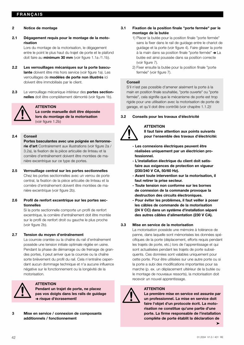
2 Notice de montage
2.1 Dégagement requis pour le montage de la moto-risation Lors du montage de la motorisation, le dégagemententre le point le plus haut du trajet de porte et le plafonddoit faire au minimum 30 mm (voir figure 1.1a /1.1b).
2.2 Les verrouillages mécaniques sur la porte bascu-lante doivent être mis hors service (voir figure 1a). Lesverrouillages de modèles de porte non illustrés icidoivent être immobilisés par le client.
2.3 Le verrouillage mécanique intérieur des portes section-nelles doit être complètement démonté (voir figure 1b).
ATTENTIONLa corde manuelle doit être déposée lors du montage de la motorisation(voir figure 1.2b)
2.4 ConseilPortes basculantes avec une poignée en ferronne-rie d'art Contrairement aux illustrations (voir figure 2a /3.2a), la fixation de la pièce articulée de linteau et la cornière d'entraînement doivent être montées de ma-nière excentrique sur ce type de portes.
2.5 Verrouillage central sur les portes sectionnellesChez les portes sectionnelles avec un verrou de portecentral, la fixation de la pièce articulée de linteau et lacornière d'entraînement doivent être montées de ma-nière excentrique (voir figure 2b).
2.6 Profil de renfort excentrique sur les portes sec-tionnellesSi la porte sectionnelle comporte un profil de renfortexcentrique, la cornière d'entraînement doit être montéesur le profil de renfort droit ou gauche le plus proche(voir figure 2b).
2.7 Tension du moyen d'entraînementLa courroie crantée ou la chaîne du rail d'entraînementpossède une tension initiale optimale réglée en usine.Pendant la phase de démarrage ou de freinage de gran-des portes, il peut arriver que la courroie ou la chaînesorte brièvement du profil du rail. Cela n'entraîne cepen-dant aucun dommage technique et n'a aucune influencenégative sur le fonctionnement ou la longévité de lamotorisation.
ATTENTIONPendant un trajet de porte, ne placez pas vos doigts dans les rails de guidage risque d'écrasement!
3 Mise en service / connexion de composants additionnels / fonctionnement
3.1 Fixation de la position finale "porte fermée" par lemontage de la butée1) Placer la butée pour la position finale "porte fermée"
sans la fixer dans le rail de guidage entre le chariot deguidage et la porte (voir figure 4). Faire glisser la porteà la main dans sa position finale "porte fermée" Labutée est ainsi poussée dans sa position correcte(voir figure 7).
2) Fixer ensuite la butée pour la position finale "porte fermée" (voir figure 7).
ConseilS'il n'est pas possible d'amener aisément la porte à la main en position finale souhaitée, "porte ouverte" ou "portefermée", cela signifie que le mécanisme de porte est troprigide pour une utilisation avec la motorisation de porte degarage, et qu'il doit être contrôlé (voir chapitre 1.1.2)!
3.2 Conseils pour les travaux d'électricité
ATTENTIONIl faut faire attention aux points suivantspour l'ensemble des travaux d'électricité:
- Les connexions électriques peuvent être réalisées uniquement par un électricien pro-fessionnel.
- L'installation électrique du client doit satis-faire aux exigences de protection en vigueur (230/240 V CA, 50/60 Hz).
- Avant toute intervention sur la motorisation, ilfaut retirer la prise secteur.
- Toute tension non conforme sur les bornes de connexion de la commande provoque ladestruction des circuits électroniques.
- Pour éviter les problèmes, il faut veiller à poserles câbles de commande de la motorisation (24 V CC) dans un système d'installation séparédes autres câbles d'alimentation (230 V CA).
3.3 Mise en service de la motorisationLa motorisation possède une mémoire à tolérance depanne, dans laquelle sont mémorisées les données spé-cifiques de la porte (déplacement, efforts requis pendantles trajets de porte, etc.) lors de l'apprentissage et quisont actualisées pendant les trajets de porte subsé-quents. Ces données sont valables uniquement pourcette porte. Pour être utilisées sur une autre porte ou sila porte a subi des modifications importantes pour samarche (p. ex. un déplacement ultérieur de la butée oule montage de nouveaux ressorts), la motorisation doitrecevoir un nouvel apprentissage.
ATTENTIONLa première mise en service est assurée parun professionnel. La mise en service doitfaire l'objet d'un protocole écrit. La moto-risation ne constitue qu'une partie d'uneporte. La firme responsable de l'installationcomplète de porte établit la déclaration de
42 01.2004 V1.0 / 401 RE
F R A N Ç A I S
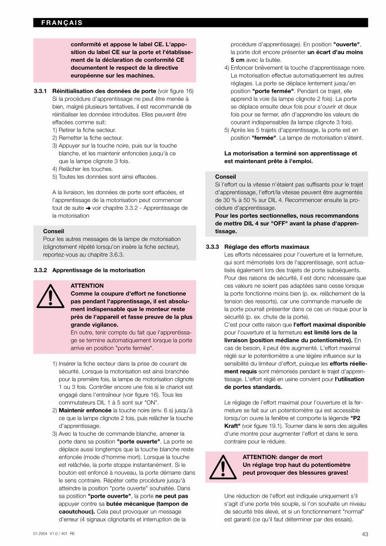
4301.2004 V1.0 / 401 RE
conformité et appose le label CE. L'appo-sition du label CE sur la porte et l'établisse-ment de la déclaration de conformité CEdocumentent le respect de la directiveeuropéenne sur les machines.
3.3.1 Réinitialisation des données de porte (voir figure 16)Si la procédure d'apprentissage ne peut être menée àbien, malgré plusieurs tentatives, il est recommandé deréinitialiser les données introduites. Elles peuvent êtreeffacées comme suit:1) Retirer la fiche secteur.2) Remetter la fiche secteur.3) Appuyer sur la touche noire, puis sur la touche
blanche, et les maintenir enfoncées jusqu'à ce que la lampe clignote 3 fois.
4) Relâcher les touches.5) Toutes les données sont ainsi effacées.
A la livraison, les données de porte sont effacées, etl'apprentissage de la motorisation peut commencer tout de suite voir chapitre 3.3.2 - Apprentissage de la motorisation
ConseilPour les autres messages de la lampe de motorisation (clignotement répété lorsqu'on insère la fiche secteur),reportez-vous au chapitre 3.6.3.
3.3.2 Apprentissage de la motorisation
ATTENTIONComme la coupure d'effort ne fonctionnepas pendant l'apprentissage, il est absolu-ment indispensable que le monteur resteprès de l'appareil et fasse preuve de la plusgrande vigilance.En outre, tenir compte du fait que l'apprentissa-ge se termine automatiquement lorsque la portearrive en position "porte fermée".
1) Insérer la fiche secteur dans la prise de courant desécurité. Lorsque la motorisation est ainsi branchéepour la première fois, la lampe de motorisation clignote1 ou 3 fois. Contrôler encore une fois si le chariot estengagé dans l'entraîneur (voir figure 16). Tous lescommutateurs DIL 1 à 5 sont sur "ON".
2) Maintenir enfoncée la touche noire (env. 6 s) jusqu'àce que la lampe clignote 2 fois, puis relâcher la touched'apprentissage.
3) Avec la touche de commande blanche, amener laporte dans sa position "porte ouverte". La porte sedéplace aussi longtemps que la touche blanche resteenfoncée (mode d'homme mort). Lorsque la toucheest relâchée, la porte stoppe instantanément. Si lebouton est enfoncé à nouveau, la porte démarre dansle sens contraire. Répéter cette procédure jusqu'àatteindre la position "porte ouverte" souhaitée. Danssa position "porte ouverte", la porte ne peut pasappuyer contre sa butée mécanique (tampon decaoutchouc). Cela peut provoquer un message d'erreur (4 signaux clignotants et interruption de la
procédure d'apprentissage). En position "ouverte", la porte doit encore présenter un écart d'au moins 5 cm avec la butée.
4) Enfoncer brièvement la touche d'apprentissage noire.La motorisation effectue automatiquement les autresréglages. La porte se déplace lentement jusqu'enposition "porte fermée". Pendant ce trajet, elleapprend la voie (la lampe clignote 2 fois). La porte se déplace ensuite deux fois pour s'ouvrir et deux fois pour se fermer, afin d'apprendre les valeurs decourant indispensables (la lampe clignote 3 fois).
5) Après les 5 trajets d'apprentissage, la porte est enposition "fermée". La lampe de motorisation s'éteint.
La motorisation a terminé son apprentissage et est maintenant prête à l'emploi.
ConseilSi l'effort ou la vitesse n'étaient pas suffisants pour le trajetd'apprentissage, l'effort/la vitesse peuvent être augmentésde 30 % à 50 % sur DIL 4. Recommencer ensuite la pro-cédure d'apprentissage.Pour les portes sectionnelles, nous recommandonsde mettre DIL 4 sur "OFF" avant la phase d'appren-tissage.
3.3.3 Réglage des efforts maximauxLes efforts nécessaires pour l'ouverture et la fermeture,qui sont mémorisés lors de l'apprentissage, sont actua-lisés également lors des trajets de porte subséquents.Pour des raisons de sécurité, il est donc nécessaire queces valeurs ne soient pas adaptées sans cesse lorsquela porte fonctionne moins bien (p. ex. relâchement de latension des ressorts), car une commande manuelle dela porte pourrait présenter dans ce cas un risque pour lasécurité (p. ex. chute de la porte).C'est pour cette raison que l'effort maximal disponiblepour l'ouverture et la fermeture est limité lors de lalivraison (position médiane du potentiomètre). Encas de besoin, il peut être augmenté. L'effort maximalréglé sur le potentiomètre a une légère influence sur lasensibilité du limiteur d'effort, puisque les efforts réelle-ment requis sont mémorisés pendant le trajet d'appren-tissage. L'effort réglé en usine convient pour l'utilisationde portes standards.
Le réglage de l'effort maximal pour l'ouverture et la fer-meture se fait sur un potentiomètre qui est accessiblelorsqu'on ouvre la fenêtre et comporte la légende "P2Kraft" (voir figure 19.1). Tourner dans le sens des aiguillesd'une montre pour augmenter l'effort et dans le senscontraire pour le réduire.
ATTENTION: danger de mortUn réglage trop haut du potentiomètre peut provoquer des blessures graves!
Une réduction de l'effort est indiquée uniquement s'ils'agit d'une porte très souple, si l'on souhaite un niveaude sécurité très élevé, et si un fonctionnement "normal"est garanti (ce qu'il faut déterminer par des essais).
F R A N Ç A I S
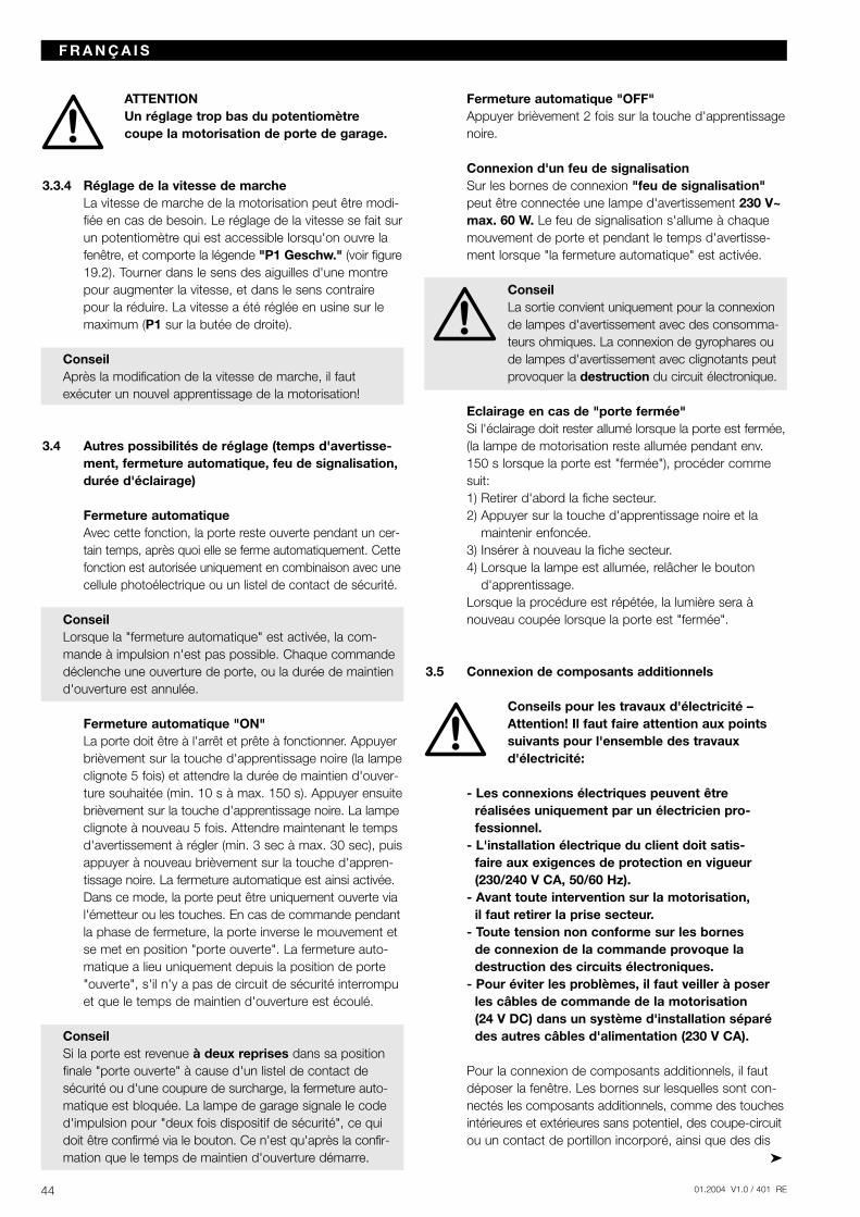
ATTENTIONUn réglage trop bas du potentiomètre coupe la motorisation de porte de garage.
3.3.4 Réglage de la vitesse de marcheLa vitesse de marche de la motorisation peut être modi-fiée en cas de besoin. Le réglage de la vitesse se fait surun potentiomètre qui est accessible lorsqu'on ouvre lafenêtre, et comporte la légende "P1 Geschw." (voir figure19.2). Tourner dans le sens des aiguilles d'une montrepour augmenter la vitesse, et dans le sens contrairepour la réduire. La vitesse a été réglée en usine sur lemaximum (P1 sur la butée de droite).
ConseilAprès la modification de la vitesse de marche, il faut exécuter un nouvel apprentissage de la motorisation!
3.4 Autres possibilités de réglage (temps d'avertisse-ment, fermeture automatique, feu de signalisation,durée d'éclairage)
Fermeture automatiqueAvec cette fonction, la porte reste ouverte pendant un cer-tain temps, après quoi elle se ferme automatiquement. Cettefonction est autorisée uniquement en combinaison avec unecellule photoélectrique ou un listel de contact de sécurité.
ConseilLorsque la "fermeture automatique" est activée, la com-mande à impulsion n'est pas possible. Chaque commandedéclenche une ouverture de porte, ou la durée de maintiend'ouverture est annulée.
Fermeture automatique "ON"La porte doit être à l'arrêt et prête à fonctionner. Appuyerbrièvement sur la touche d'apprentissage noire (la lampeclignote 5 fois) et attendre la durée de maintien d'ouver-ture souhaitée (min. 10 s à max. 150 s). Appuyer ensuitebrièvement sur la touche d'apprentissage noire. La lampeclignote à nouveau 5 fois. Attendre maintenant le tempsd'avertissement à régler (min. 3 sec à max. 30 sec), puisappuyer à nouveau brièvement sur la touche d'appren-tissage noire. La fermeture automatique est ainsi activée.Dans ce mode, la porte peut être uniquement ouverte vial'émetteur ou les touches. En cas de commande pendantla phase de fermeture, la porte inverse le mouvement etse met en position "porte ouverte". La fermeture auto-matique a lieu uniquement depuis la position de porte"ouverte", s'il n'y a pas de circuit de sécurité interrompuet que le temps de maintien d'ouverture est écoulé.
ConseilSi la porte est revenue à deux reprises dans sa positionfinale "porte ouverte" à cause d'un listel de contact desécurité ou d'une coupure de surcharge, la fermeture auto-matique est bloquée. La lampe de garage signale le coded'impulsion pour "deux fois dispositif de sécurité", ce quidoit être confirmé via le bouton. Ce n'est qu'après la confir-mation que le temps de maintien d'ouverture démarre.
Fermeture automatique "OFF"Appuyer brièvement 2 fois sur la touche d'apprentissagenoire.
Connexion d'un feu de signalisationSur les bornes de connexion "feu de signalisation"peut être connectée une lampe d'avertissement 230 V~max. 60 W. Le feu de signalisation s'allume à chaquemouvement de porte et pendant le temps d'avertisse-ment lorsque "la fermeture automatique" est activée.
ConseilLa sortie convient uniquement pour la connexionde lampes d'avertissement avec des consomma-teurs ohmiques. La connexion de gyrophares oude lampes d'avertissement avec clignotants peutprovoquer la destruction du circuit électronique.
Eclairage en cas de "porte fermée"Si l'éclairage doit rester allumé lorsque la porte est fermée,(la lampe de motorisation reste allumée pendant env.150 s lorsque la porte est "fermée"), procéder commesuit:1) Retirer d'abord la fiche secteur.2) Appuyer sur la touche d'apprentissage noire et la
maintenir enfoncée.3) Insérer à nouveau la fiche secteur.4) Lorsque la lampe est allumée, relâcher le bouton
d'apprentissage.Lorsque la procédure est répétée, la lumière sera à nouveau coupée lorsque la porte est "fermée".
3.5 Connexion de composants additionnels
Conseils pour les travaux d'électricité –Attention! Il faut faire attention aux pointssuivants pour l'ensemble des travauxd'électricité:
- Les connexions électriques peuvent être réalisées uniquement par un électricien pro-fessionnel.
- L'installation électrique du client doit satis-faire aux exigences de protection en vigueur(230/240 V CA, 50/60 Hz).
- Avant toute intervention sur la motorisation, il faut retirer la prise secteur.
- Toute tension non conforme sur les bornes de connexion de la commande provoque ladestruction des circuits électroniques.
- Pour éviter les problèmes, il faut veiller à poserles câbles de commande de la motorisation (24 V DC) dans un système d'installation séparédes autres câbles d'alimentation (230 V CA).
Pour la connexion de composants additionnels, il fautdéposer la fenêtre. Les bornes sur lesquelles sont con-nectés les composants additionnels, comme des touchesintérieures et extérieures sans potentiel, des coupe-circuitou un contact de portillon incorporé, ainsi que des dis
44 01.2004 V1.0 / 401 RE
F R A N Ç A I S
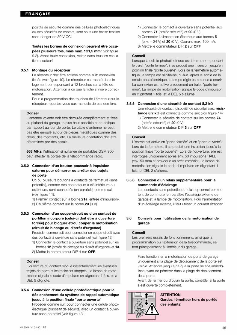
4501.2004 V1.0 / 401 RE
positifs de sécurité comme des cellules photoélectriquesou des sécurités de contact, sont sous une basse tensionsans danger de 30 V CC.
Toutes les bornes de connexion peuvent être occu-pées plusieurs fois, mais max. 1x1,5 mm2 (voir figure9.2). Avant toute connexion, retirez dans tous les cas lafiche secteur!
3.5.1 Montage du récepteurLe récepteur doit être enfiché comme suit: connexionfichée (voir figure 10). Le récepteur est monté dans lelogement correspondant à 12 broches sur la tête demotorisation. Attention à ce que la fiche s'insère correc-tement.Pour la programmation des touches de l'émetteur sur lerécepteur, reportez-vous aux manuels de ces derniers.
ConseilL'antenne volante doit être déroulée complètement et fixéeau plafond du garage, le plus haut possible et en obliquepar rapport au jour de porte. Le câble d'antenne ne peutpas être enroulé autour de pièces métalliques comme desclous, des montants, etc. La meilleure orientation doit êtredéterminée par des essais.
868 MHz: l'utilisation simultanée de portables GSM 900peut affecter la portée de la télécommande radio.
3.5.2 Connexion d'un bouton-poussoir à impulsionexterne pour démarrer ou arrêter des trajets de porteUn ou plusieurs boutons à contacts de fermeture (sanspotentiel), comme des contacteurs à clé intérieurs ouextérieurs, sont connectés (en parallèle) comme suit(voir figure 11):1) Premier contact sur la borne 21a (entrée d'impulsion).2) Deuxième contact sur la borne 20 (0 V).
3.5.3 Connexion d'un coupe-circuit ou d'un contact deportillon incorporé (celui-ci doit être à ouvertureforcée) pour bloquer et/ou couper la motorisation(circuit de blocage ou d'arrêt d'urgence)Procéder comme suit pour connecter un coupe-circuit avecdes contacts à ouverture sans potentiel (voir figure 12):1) Connecter le contact à ouverture sans potentiel sur les
bornes 12 (entrée de blocage ou d'arrêt d'urgence) et 13.2) Mettre le commutateur DIP 1 sur OFF.
ConseilL'ouverture du contact bloque instantanément les éventuelstrajets de porte et les maintient stoppés. La lampe de moto-risation signale le code d'impulsion en clignotant 1 fois, et laDEL 5 clignote.
3.5.4 Connexion d'une cellule photoélectrique pour ledéclenchement du système de rappel automatiquejusqu'à la position finale "porte ouverte"Procéder comme suit pour connecter une cellule photo-électrique (dispositif de sécurité) avec un contact à ouver-ture sans potentiel (voir figure 13):
1) Connecter le contact à ouverture sans potentiel auxbornes 71 (entrée sécurité) et 20 (0 V).
2) Connecter l'alimentation électrique aux bornes 5(env. + 24 V) et 20 (0 V). Courant max. 100 mA.
3) Mettre le commutateur DIP 2 sur OFF.
ConseilLorsque la cellule photoélectrique est interrompue pendantle trajet "porte fermée", il se produit une inversion jusqu'enposition finale "porte ouverte". Lors de la fermeture automa-tique, le temps est réinitialisé, c.-à-d. après la sortie de lacellule photoélectrique, le temps réglé commence à courir.La connexion est active uniquement en trajet "porte fer-mée". La lampe de motorisation signale le code d'impulsionen clignotant 1 fois, et la DEL 5 s'allume.
3.5.5 Connexion d'une sécurité de contact 8,2 kΩUne sécurité de contact (dispositif de sécurité) avec résis-tance 8,2 kΩ est connecté comme suit (voir figure 14):1) Connecter la sécurité de contact sur les bornes 74
(entrée sécurité) et 20 (0 V).2) Mettre le commutateur DIP 3 sur OFF.
ConseilL'entrée est active en "porte fermée" et en "porte ouverte".Lors de la fermeture, il se produit une inversion jusqu'à laposition finale "porte ouverte". Lors de l'ouverture, elle estinterrogée uniquement après env. 50 impulsions HALL (env. 50 mm) et provoque un arrêt immédiat. La lampe demotorisation signale le code d'impulsion en clignotant 1fois, et DEL 2 s'allume.
3.5.6 Connexion d'un relais supplémentaire pour lacommande d'éclairageLes contacts sans potentiel du relais optionnel permet-tent de commuter en parallèle l'éclairage externe degarage et la lampe de motorisation. Pour l'alimentationd'un éclairage externe, il faut utiliser un courant étranger!
3.6 Conseils pour l'utilisation de la motorisation degarage
ConseilLes premiers essais de fonctionnement, ainsi que la programmation ou l'extension de la télécommande, se font principalement à l'intérieur du garage.
Faire fonctionner la motorisation de porte de garage uniquement si la plage de déplacement de la porte estvisible. Attendre jusqu'à ce que la porte se soit immobi-lisée avant de pénétrer dans la plage de déplacementde la porte. Avant de fermer ou d'ouvrir la porte, contrôler si la portes'est ouverte complètement.
ATTENTIONGardez l'émetteur hors de portée des enfants!
F R A N Ç A I S
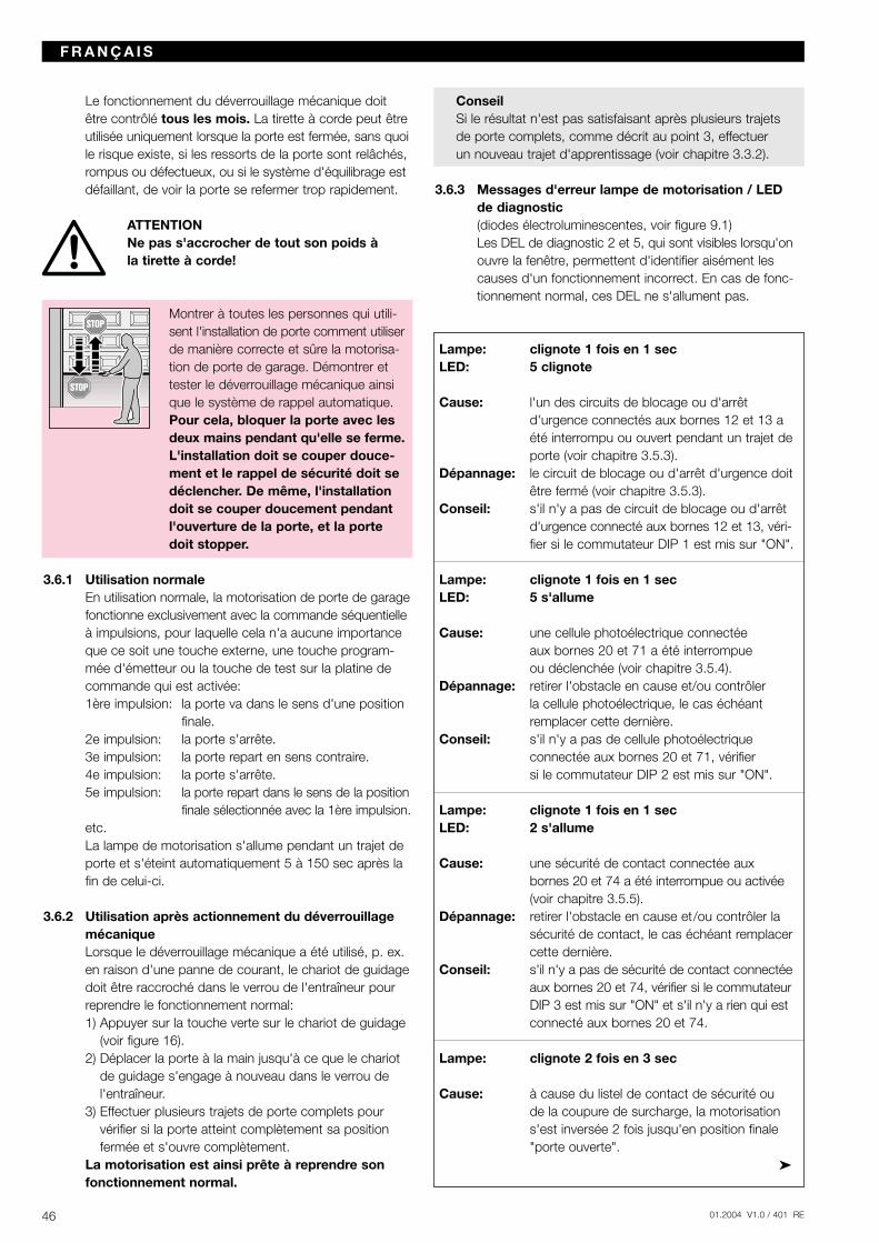
Le fonctionnement du déverrouillage mécanique doitêtre contrôlé tous les mois. La tirette à corde peut êtreutilisée uniquement lorsque la porte est fermée, sans quoile risque existe, si les ressorts de la porte sont relâchés,rompus ou défectueux, ou si le système d'équilibrage estdéfaillant, de voir la porte se refermer trop rapidement.
ATTENTIONNe pas s'accrocher de tout son poids à la tirette à corde!
Montrer à toutes les personnes qui utili-sent l'installation de porte comment utiliserde manière correcte et sûre la motorisa-tion de porte de garage. Démontrer ettester le déverrouillage mécanique ainsique le système de rappel automatique.Pour cela, bloquer la porte avec lesdeux mains pendant qu'elle se ferme.L'installation doit se couper douce-ment et le rappel de sécurité doit sedéclencher. De même, l'installationdoit se couper doucement pendantl'ouverture de la porte, et la portedoit stopper.
3.6.1 Utilisation normaleEn utilisation normale, la motorisation de porte de garagefonctionne exclusivement avec la commande séquentielleà impulsions, pour laquelle cela n'a aucune importanceque ce soit une touche externe, une touche program-mée d'émetteur ou la touche de test sur la platine decommande qui est activée:1ère impulsion: la porte va dans le sens d'une position
finale.2e impulsion: la porte s'arrête.3e impulsion: la porte repart en sens contraire.4e impulsion: la porte s'arrête.5e impulsion: la porte repart dans le sens de la position
finale sélectionnée avec la 1ère impulsion.etc.La lampe de motorisation s'allume pendant un trajet deporte et s'éteint automatiquement 5 à 150 sec après lafin de celui-ci.
3.6.2 Utilisation après actionnement du déverrouillagemécaniqueLorsque le déverrouillage mécanique a été utilisé, p. ex.en raison d'une panne de courant, le chariot de guidagedoit être raccroché dans le verrou de l'entraîneur pourreprendre le fonctionnement normal:1) Appuyer sur la touche verte sur le chariot de guidage
(voir figure 16).2) Déplacer la porte à la main jusqu'à ce que le chariot
de guidage s'engage à nouveau dans le verrou del'entraîneur.
3) Effectuer plusieurs trajets de porte complets pourvérifier si la porte atteint complètement sa positionfermée et s'ouvre complètement.
La motorisation est ainsi prête à reprendre sonfonctionnement normal.
ConseilSi le résultat n'est pas satisfaisant après plusieurs trajets de porte complets, comme décrit au point 3, effectuer un nouveau trajet d'apprentissage (voir chapitre 3.3.2).
3.6.3 Messages d'erreur lampe de motorisation / LED de diagnostic(diodes électroluminescentes, voir figure 9.1)Les DEL de diagnostic 2 et 5, qui sont visibles lorsqu'onouvre la fenêtre, permettent d'identifier aisément lescauses d'un fonctionnement incorrect. En cas de fonc-tionnement normal, ces DEL ne s'allument pas.
Lampe: clignote 1 fois en 1 secLED: 5 clignote
Cause: l'un des circuits de blocage ou d'arrêt d'urgence connectés aux bornes 12 et 13 a été interrompu ou ouvert pendant un trajet de porte (voir chapitre 3.5.3).
Dépannage: le circuit de blocage ou d'arrêt d'urgence doit être fermé (voir chapitre 3.5.3).
Conseil: s'il n'y a pas de circuit de blocage ou d'arrêt d'urgence connecté aux bornes 12 et 13, véri-fier si le commutateur DIP 1 est mis sur "ON".
Lampe: clignote 1 fois en 1 secLED: 5 s'allume
Cause: une cellule photoélectrique connectée aux bornes 20 et 71 a été interrompue ou déclenchée (voir chapitre 3.5.4).
Dépannage: retirer l'obstacle en cause et/ou contrôler la cellule photoélectrique, le cas échéant remplacer cette dernière.
Conseil: s'il n'y a pas de cellule photoélectrique connectée aux bornes 20 et 71, vérifier si le commutateur DIP 2 est mis sur "ON".
Lampe: clignote 1 fois en 1 secLED: 2 s'allume
Cause: une sécurité de contact connectée aux bornes 20 et 74 a été interrompue ou activée(voir chapitre 3.5.5).
Dépannage: retirer l'obstacle en cause et/ou contrôler la sécurité de contact, le cas échéant remplacer cette dernière.
Conseil: s'il n'y a pas de sécurité de contact connectée aux bornes 20 et 74, vérifier si le commutateur DIP 3 est mis sur "ON" et s'il n'y a rien qui estconnecté aux bornes 20 et 74.
Lampe: clignote 2 fois en 3 sec
Cause: à cause du listel de contact de sécurité ou de la coupure de surcharge, la motorisation s'est inversée 2 fois jusqu'en position finale "porte ouverte".
46 01.2004 V1.0 / 401 RE
F R A N Ç A I S
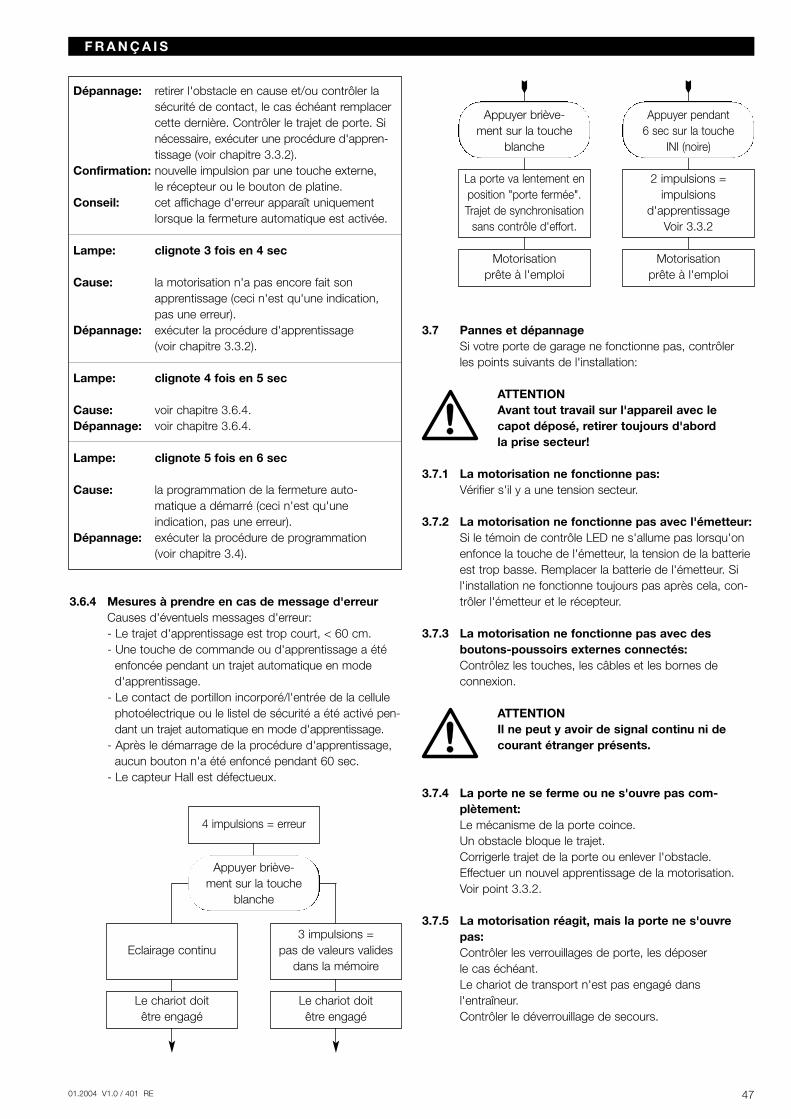
4701.2004 V1.0 / 401 RE
Dépannage: retirer l'obstacle en cause et/ou contrôler la sécurité de contact, le cas échéant remplacer cette dernière. Contrôler le trajet de porte. Si nécessaire, exécuter une procédure d'appren-tissage (voir chapitre 3.3.2).
Confirmation: nouvelle impulsion par une touche externe, le récepteur ou le bouton de platine.
Conseil: cet affichage d'erreur apparaît uniquement lorsque la fermeture automatique est activée.
Lampe: clignote 3 fois en 4 sec
Cause: la motorisation n'a pas encore fait son apprentissage (ceci n'est qu'une indication, pas une erreur).
Dépannage: exécuter la procédure d'apprentissage (voir chapitre 3.3.2).
Lampe: clignote 4 fois en 5 sec
Cause: voir chapitre 3.6.4.Dépannage: voir chapitre 3.6.4.
Lampe: clignote 5 fois en 6 sec
Cause: la programmation de la fermeture auto-matique a démarré (ceci n'est qu'une indication, pas une erreur).
Dépannage: exécuter la procédure de programmation (voir chapitre 3.4).
3.6.4 Mesures à prendre en cas de message d'erreurCauses d'éventuels messages d'erreur:- Le trajet d'apprentissage est trop court, < 60 cm.- Une touche de commande ou d'apprentissage a été
enfoncée pendant un trajet automatique en moded'apprentissage.
- Le contact de portillon incorporé/l'entrée de la cellulephotoélectrique ou le listel de sécurité a été activé pen-dant un trajet automatique en mode d'apprentissage.
- Après le démarrage de la procédure d'apprentissage,aucun bouton n'a été enfoncé pendant 60 sec.
- Le capteur Hall est défectueux.
3.7 Pannes et dépannageSi votre porte de garage ne fonctionne pas, contrôler les points suivants de l'installation:
ATTENTIONAvant tout travail sur l'appareil avec lecapot déposé, retirer toujours d'abord la prise secteur!
3.7.1 La motorisation ne fonctionne pas:Vérifier s'il y a une tension secteur.
3.7.2 La motorisation ne fonctionne pas avec l'émetteur:Si le témoin de contrôle LED ne s'allume pas lorsqu'onenfonce la touche de l'émetteur, la tension de la batterieest trop basse. Remplacer la batterie de l'émetteur. Sil'installation ne fonctionne toujours pas après cela, con-trôler l'émetteur et le récepteur.
3.7.3 La motorisation ne fonctionne pas avec des boutons-poussoirs externes connectés:Contrôlez les touches, les câbles et les bornes de connexion.
ATTENTIONIl ne peut y avoir de signal continu ni decourant étranger présents.
3.7.4 La porte ne se ferme ou ne s'ouvre pas com-plètement:Le mécanisme de la porte coince.Un obstacle bloque le trajet.Corrigerle trajet de la porte ou enlever l'obstacle.Effectuer un nouvel apprentissage de la motorisation.Voir point 3.3.2.
3.7.5 La motorisation réagit, mais la porte ne s'ouvrepas:Contrôler les verrouillages de porte, les déposer le cas échéant.Le chariot de transport n'est pas engagé dans l'entraîneur.Contrôler le déverrouillage de secours.
F R A N Ç A I S
Eclairage continu
4 impulsions = erreur
3 impulsions = pas de valeurs valides
dans la mémoire
Le chariot doit être engagé
Le chariot doit être engagé
Appuyer briève-ment sur la touche
blanche
La porte va lentement enposition "porte fermée".Trajet de synchronisation
sans contrôle d'effort.
2 impulsions = impulsions
d'apprentissage Voir 3.3.2
Motorisation prête à l'emploi
Appuyer pendant6 sec sur la touche
INI (noire)
Motorisation prête à l'emploi
Appuyer briève-ment sur la touche
blanche
3.7.6 La porte inverse son mouvement en cours de fermeture:Le mécanisme de la porte coince.Un obstacle bloque le trajet.Corriger le trajet de la porte ou enlever l'obstacle.Effectuer un nouvel apprentissage. Voir point 3.3.2.
3.7.7 Panne d'éclairage:Retirer la prise secteur.Déposer la fenêtre.Vérifier si la lampe halogène est bien enfichée.Remplacer la lampe halogène (G 4/20 W, transparente).
3.7.8 Portée trop faible de l'émetteur:Contrôler la batterie de l'émetteur.Corriger la disposition de l'antenne.
4 Conditions de garantie
Durée de la garantieEn plus de la garantie légale du vendeur découlant ducontrat de vente, nous accordons une garantie pour unedurée de 24 mois à partir de la date d'achat. L'appel à la garantie ne prolonge pas cette dernière. Pour leslivraisons de remplacement et les travaux d'améliorationultérieurs, la durée de garantie est de six mois, mais auminimum la durée de garantie initiale.
ConditionsLa revendication de garantie est valable uniquementpour le pays dans lequel l'appareil a été acheté. Lesmarchandises doivent avoir été achetées selon le canalde distribution que nous avons prescrit. La revendicationde garantie porte uniquement sur les dommages à l'objetmême du contrat. Le remboursement de frais pour ledémontage et le montage, le contrôle de pièces corres-pondantes, ainsi que les revendications pour pertes derevenus et indemnisation de dommages sont exclus dela garantie. La facture fait office de preuve pour votrerevendication de garantie.
ServicesPendant la durée de la garantie, nous réparons tous les manquements au produit qui peuvent être attribués à un défaut de matériaux ou de fabrication. Selon notrechoix, nous nous obligeons à remplacer les marchandisesdéfectueuses par des rechanges sans défaillance, de lesaméliorer ou d'indemniser leur moins-value.
Sont exclus, les dommages dus à:- un montage et un raccordement incorrects- une mise en service et une exploitation incorrectes- des influences externes tels que le feu, l'eau, des
conditions ambiantes anormales- des dommages mécaniques par accident, chute,
collision- un dommage par négligence ou volontaire- une usure normale- une réparation par une personne non qualifiée
- l'utilisation de pièces d'origine étrangère- l'enlèvement ou l'effacement du numéro de série
Les pièces remplacées deviennent notre propriété.
5 Caractéristiques techniques
Connexion réseau: 230/240 V, 50/60 Hz Veille env. 1 W
Indice de protection: uniquement pour pièces sèches
Automatisme d'arrêt: est appris automatiquement et séparément pour les deux sens.
Coupure en position à auto-apprentissage, sansfinale/limitation usure, car réalisée sans com-d'effort: mutateur mécanique, en outre
limiteur de fonctionnement intégré d'env. 140 s. Automa-tisme d'arrêt avec réglage lors de chaque trajet de porte.
Force de traction et de poussée: voir plaquette signalétique
Moteur: moteur à courant continu avec capteur Hall
Transformateur: avec protection thermique
Connexion: technique de connexion sans vis pour appareils externes avec basse tension de sécurité 24 V CC, p. ex. bouton intérieuret extérieur avec commande à impulsion.
Fonctions spéciales: - éclairage de motorisation- possibilité de connecter un
commutateur d'arrêt/coupe-circuit
- possibilité de connecter une cellule photoélectrique et une sécurité de contact
- possibilité de connecter une lampe d'avertissement 230 V CA
- possibilité de connecter des relais optionnels pour un éclairage extérieur
Déverrouillage à activer de l'intérieur par câblerapide: de traction en cas de panne de
courant
Télécommande: émetteur à 4 touches RC BE 868/4 (868,360 MHz) et récep-teur séparé.
48 01.2004 V1.0 / 401 RE
F R A N Ç A I S
4901.2004 V1.0 / 401 RE
Ferrure universelle: pour portes basculantes et sectionnelles
Vitesse de marche 135 mm/s (en fonction de lade porte: taille et du poids de la porte)
Bruit aérien émis par la motorisation: ≤ 70 dB (A)
Rail de guidage: extrêmement plat (30 mm), avec sécurité anti-relevage intégrée. Rail en exécution pourcourroie crantée ou chaîne.
6 Démontage et mise en déchargeEn cas de démontage, les dispositions de sécurité doiventêtre respectées également. La mise en décharge doit sefaire conformément aux dispositions en vigueur.
Sous réserve de modifications techniques.
Edition: septembre 2003
F R A N Ç A I S
2 Istruzioni per il montaggio
2.1 Spazio libero necessario per il montaggio della motorizzazionePer il montaggio dell'unità di motorizzazione lo spaziolibero fra il punto massimo della traiettoria della porta e il soffitto deve essere di almeno 30 mm (vedere figura1.1a / 1.1b).
2.2 I dispositivi di bloccaggio meccanici della portabasculante devono essere disattivati (vedere figura 1a).Nei modelli di porta non raffigurati nelle presentiistruzioni i chiavistelli a scatto devono essere bloccatidal cliente.
2.3 Il bloccaggio interno meccanico del portone sezio-nale deve essere completamente smontato (vederefigura 1b).
ATTENZIONEDurante il montaggio della moto-rizzazione togliere il cordoncino(vedere figura 1.2b)
2.4 AvvertenzaPorte basculanti con maniglia in ferro battutoDiversamente dalle raffigurazioni nella parte illustrata(vedere figura 2a / 3.2a), in queste porte il fissaggiodell'attacco snodato e il braccio di trascinamentodevono essere applicati fuori asse.
2.5 Portone sezionale con serratura centraleNei portoni sezionali con serratura centrale l'attaccosnodato e il braccio di trascinamento devono essereapplicati fuori asse (vedere figura 2b).
2.6 Portone sezionale con profilo di rinforzo applicatofuori asseIn caso di profilo di rinforzo applicato fuori asse sul por-tone sezionale, il braccio di trascinamento deve esseremontato a destra o sinistra del profilo di rinforzo più vicino(vedere figura 2b).
2.7 Tensionamento del mezzo di trasmissioneLa cinghia dentata o la catena della guida di traino por-tante è già perfettamente in tensione (impostazione difabbrica). Nelle porte di grandi dimensioni può succedereche la cinghia o la catena, al momento dell'avvio e delrallentamento, spunti brevemente dalla guida. Questofatto non comporta, però, alcun difetto tecnico né haalcun effetto negativo sul funzionamento e sulla duratadella motorizzazione.
ATTENZIONENon infilare le dita nella guida durante la manovra della porta Pericolo di schiacciamento!
3 Messa in funzione / collegamento di componentisupplementari / funzionamento
3.1 Stabilire la posizione di fine corsa "Chiusura" tramite montaggio dell'arresto di fine corsa1) Infilare l'arresto per la posizione di fine corsa di
"Chiusura" nella guida di traino tra il carrello e la porta(vedi figura 4) e manovrare manualmente la portanella posizione di fine corsa di "Chiusura" in talmodo l'arresto di fine corsa viene spinto nella posi-zione giusta (vedere figura 7).
2) Successivamente fissare l'arresto per la posizione difine corsa di "Apertura" (vedere figura 7).
AvvertenzaSe la manovra manuale della porta nella posizione di finecorsa scelta di "Apertura" o "Chiusura" risulta difficoltosa,significa che la meccanica della porta è troppo pesante per il funzionamento con motorizzazione e che deve esserecontrollata (vedere capitolo 1.1.2)!
3.2 Avvertenze per gli interventi sull'impianto elettrico
ATTENZIONEPer tutti gli interventi sull'impianto elettricotener conto dei seguenti punti:
- I collegamenti elettrici devono essere effettuatisoltanto da uno specialista!
- L'installazione elettrica, a cura del cliente, deveessere conforme alle relative norme di protezione(230/240 V AC, 50/60 Hz)!
- Staccare la spina di rete prima di intervenire sullamotorizzazione!
- Una tensione esterna sui morsetti dell'unità dicomando danneggia gravemente l'intero impiantoelettronico!
- Per evitare malfunzionamenti assicurare che lelinee di controllo della motorizzazione (24 V DC)vengano posate in un sistema di installazione se-parato dalle altre linee di alimentazione (230 V AC)!
3.3 Messa in funzione della motorizzazioneLa motorizzazione è dotata di una memoria a prova dicaduta di corrente, in cui, durante la procedura di appren-dimento, vengono memorizzati i dati specifici della porta(percorso, forze necessarie durante la manovra ecc.)che vengono aggiornati durante le successive manovredella porta. Questi dati si riferiscono solo a questa portae quindi devono essere cancellati se si desidera utilizzarequesti dati per un'altra porta oppure se la porta ha note-volmente modificato il proprio comportamento di scorri-mento (ad es. in seguito ad uno spostamento dell'arrestodi fine corsa oppure in caso di montaggio di nuove molle);inoltre occorre ripetere la procedura di apprendimentoper la motorizzazione.
ATTENZIONELa prima messa in funzione deve essereeffettuata da uno specialista, che deve stilareun verbale dell’operazione. La motorizza-zione, però, è solo una parte del sistema dichiusura. La ditta responsabile per l'interosistema di chiusura deve fornire la dichiara-zione di conformità ed applicare il marchio
50 01.2004 V1.0 / 401 RE
I TA L I A N O
5101.2004 V1.0 / 401 RE
CE. Il marchio CE sulla porta e la dichiara-zione di conformità UE documentano il ris-petto della direttiva CE sui macchinari.
3.3.1 Cancellazione dei dati della porta (vedere figura 16)Nel caso in cui l'esito dell'apprendimento non fosse po-sitivo, nonostante diversi tentativi, si consiglia di effettuareun reset dei dati letti. Questi possono essere cancellatinel modo seguente:1) Staccare la spina elettrica.2) Reinserire la spina elettrica.3) Premere il tasto nero e successivamente il tasto
bianco e tenerli premuti finché la lampada non lampeggi 3 volte.
4) Rilasciare i tasti.5) Tutti i dati sono cancellati.Nello stato di consegna i dati della porta sono cancellatie la motorizzazione è pronta per la procedura di appren-dimento vedere capitolo 3.3.2 – Procedura di appren-dimento della motorizzazione
AvvertenzaPer le altre segnalazioni della lampada della motorizzazione(lampeggio ripetuto al momento dell'inserimento della spinaelettrica) vedere capitolo 3.6.3.
3.3.2 Procedura di apprendimento della motorizzazione
ATTENZIONEPoiché durante la procedura di appren-dimento l'interruzione dell'energia non funziona, è indispensabile che l'installatorerimanga vicino alla motorizzazione e prestila massima attenzione.Tener conto inoltre che la procedura di apprendi-mento termina automaticamente quando la portaha raggiunto la posizione di chiusura.
1) Inserire la spina elettrica nella presa con messa a terra.Dopo il primo inserimento della spina la lampada dellamotorizzazione lampeggia 1 o 3 volte. Verificare ancorauna volta che il carrello sia innestato nel braccio ditrascinamento (vedere figura 16). Tutti gli interruttoredual in line 1- 5 sono posizionati su "ON".
2) Tenere premuto il tasto nero (ca. 6 sec.) finché lalampada non inizii a lampeggiare. Farla lampeggiare 2 volte, poi rilasciare il tasto.
3) Manovrare la porta, premendo il tasto bianco, nellaposizione di "Apertura". La porta si muove solo se sitiene premuto il tasto bianco (manovra ad uomo pre-sente). Dopo aver rilasciato il tasto, la porta si arrestaimmediatamente; con il successivo azionamento deltasto la porta si muove nella direzione opposta. Ripetere questa procedura più volte, fino a raggiunge-re la posizione di "Apertura". Nella sua posizione di"Apertura" la porta non deve premere contro l'arrestodi fine corsa meccanico (arresto in gomma), perchéciò può far scattare un messaggio d'errore (4 segnalilampeggianti e interruzione della procedura di appren-dimento). Nella posizione di "Apertura" la porta deveavere una distanza minima di ca. 5 cm dal proprioarresto di fine corsa.
4) Premere brevemente il tasto nero. Le restanti imposta-zioni vengono effettuate automaticamente dalla moto-rizzazione. La porta si muove lentamente fino alla po-sizione di "Chiusura". Durante questa manovra lamotorizzazione apprende il percorso (la lampada lam-peggia due volte). Successivamente la porta si apre e si chiude due volte in modo che la motorizzazione'apprenda' i valori di corrente necessari (la lampadalampeggia tre volte).
5) Terminate le 5 manovre di apprendimento, la porta ènella posizione di "Chiusura", la lampada della moto-rizzazione si spegne.
La motorizzazione ha "appreso" le posizioni ed èpronta per l'uso.
AvvertenzaSe la forza o la velocità non è sufficiente per la manovra diapprendimento, con l'interruttore DIL 4 è possibile aumen-tare la forza/velocità dal 30 % al 50 %. Eseguire di nuovo la procedura di apprendimento.Per i portoni sezionali si consiglia di posizionare il DIL 4 su "OFF" prima della fase di apprendimento.
3.3.3 Impostazione degli sforzi massimiGli sforzi necessari per l'apertura e la chiusura della porta,memorizzati durante l'operazione di apprendimento,sono aggiornati e disponibili anche durante le manovresuccessive della porta. Pertanto è necessario, per motividi sicurezza, limitare l'aggiornamento di questi valori, adesempio in caso di un lento peggioramento del compor-tamento di scorrimento della porta ( ad es. nel caso siallenti la tensione della molla), perché in tal caso un'even-tuale manovra manuale della porta potrebbe comportareun rischio per la sicurezza (ad es. caduta della porta). Perquesto motivo lo sforzo massimo disponibile per l'aper-tura e la chiusura è stato limitato in fabbrica (posizionemediana del potenziometro), ma può essere aumen-tato in caso di necessità. Lo sforzo massimo regolatocon il potenziometro incide in modo minore sulla sensi-bilità del limitatore di sforzo, perché gli sforzi effettiva-mente necessari sono stati memorizzati durante laprocedura di apprendimento.Lo sforzo regolato in fabbrica è adatto per il funziona-mento di portoni standard.
Per regolare lo sforzo massimo per l'apertura e la chiusuradella porta, è disponibile un potenziometro, che si trovadietro un piccolo oblò e recante la scritta P2 sforzo(vedere figura 19.1). Ruotando il potenziometro in sensoorario, lo sforzo aumenta, ruotandolo in senso antiorario,lo sforzo diminuisce.
ATTENZIONE: PERICOLO DI MORTEUna regolazione troppo alta può causaregravi lesioni fisiche!
Una riduzione dei valori è consigliabile soltanto quandosi tratta di una porta di facile manovra, se il livello disicurezza è elevato ed è garantito un funzionamento"normale" (da accertare attraverso prove).
I TA L I A N O
ATTENZIONESe la regolazione è troppo bassa, la motorizzazione si disattiverà!
3.3.4 Regolazione della velocità di scorrimentoLa velocità della motorizzazione può essere cambiata, se necessario. Per la regolazione della velocità è dispo-nibile un potenziometro, a cui si accede dopo l'aperturadell'oblò, recante la scritta P1 velocità (vedere figura19.2). Ruotando il potenziometro in senso orario, la velo-cità aumenta, ruotandolo in senso antiorario, la velocitàdiminuisce. La velocità è regolata in fabbrica su max.(P1 su arresto destro).
AvvertenzaDopo una modifica della velocità, occorre ripetere la procedura di apprendimento della motorizzazione!
3.4 Altre possibilità di regolazione (tempo di preallarme,chiusura automatica, semaforo, temporizzazionedella luce)
Chiusura automaticaCon questa funzione la porta si chiude automaticamentedopo un determinato tempo di sosta in apertura. Questafunzione è prevista solo unitamente ad una fotocellula oun bordo di contatto di sicurezza.
AvvertenzaIn caso di impostazione su "Chiusura automatica" il funziona-mento ad impulso non è possibile. Ad ogni comando la portasi apre ovvero il tempo di sosta in apertura viene risettato.
Chiusura automatica "ON"La porta deve essere ferma e pronta per l'uso. Premerebrevemente il tasto nero (la lampada lampeggia cinquevolte) e attendere il tempo di sosta in apertura scelto (damin. 10 sec. fino a max. 150 sec.). Poi premere breve-mente lo stesso tasto nero, la lampada continua a lam-peggiare per 5 volte. Adesso attendere anche il tempo dipreallarme da regolare (da min. 3 sec. fino a max. 30 sec.),poi premere di nuovo brevemente il tasto nero. Adessola chiusura automatica è stata attivata; in questa moda-lità la porta, via radio o con il tasto, può essere soltantoaperta. Un comando trasmesso durante la fase di aper-tura fa sì che la porta inverta la direzione di marcia e simuova nella posizione di "Porta aperta". La chiusuraautomatica dalla posizione di "Porta aperta" avviene sol-tanto quando nessun circuito di sicurezza è interrotto e il tempo di sosta in apertura è trascorso.
AvvertenzaNel caso in cui la porta, a causa del bordo di contatto disicurezza o dello spegnimento per sovracorrente, abbiainvertito il senso di marcia per due volte fino alla posizionedi fine corsa di "APERTURA", la chiusura automatica vienebloccata. L'illuminazione del garage segnala con il codice aimpulsi "dispositivo di sicurezza attivato due volte", informa-zione che è necessario confermare premendo un tasto. Iltempo di sosta inizia solo dopo la conferma.
Chiusura automatica "OFF"Premere brevemente il tasto nero per 2 volte.
Collegamento semaforoAl morsetto Semaforo può essere collegata una lampadad'emergenza 230 V~ max. 60 W. Il semaforo si accendead ogni movimento della porta e durante il tempo di pre-allarme quando la funzione "chiusura automatica" è attivata.
AvvertenzaL'uscita è adatta solo per il collegamento di lampade d'emergenza con utenze ohmiche. Ilcollegamento di lampeggianti rotanti o lampaded'emergenza con intermittenza di lampeggio può danneggiare gravemente l' impiantoelettronico!
Luce accesa con "Porta chiusa"Se la luce del garage deve essere accesa anche in casodi porta chiusa (la lampada della motorizzazione in casodi "Porta chiusa" rimane accesa per ca. 150 sec.),seguire le seguenti istruzioni:1) Staccare la spina elettrica.2) Premere e tenere premuto il tasto nero.3) Reinserire la spina elettrica.4) Dopo l'accensione della lampada, rilasciare il tasto
nero.Ripetendo questa procedura, la luce accesa con "Portachiusa" viene spenta.
3.5 Collegamento di componenti supplementari
Avvertenze per gli interventi sull'impiantoelettrico – Attenzione!Per tutti gli interventi sull'impianto elettricotener conto dei seguenti punti:
- I collegamenti elettrici devono essere effettuatisoltanto da uno specialista!
- L'installazione elettrica, che spetta al cliente,deve essere conforme alle relative norme di protezione (230/240 V AC, 50/60 Hz)!
- Staccare la spina di rete prima di intervenire sulla motorizzazione!
- Una tensione esterna sui morsetti dell'unità di comando danneggia gravemente l'intero impianto elettronico!
- Per evitare malfunzionamenti assicurare che lelinee di controllo della motorizzazione (24 V DC)vengano posate separatamente dalle altre lineedi installazione (230/240 V AC)!
Per allacciare i componenti supplementari, togliere l'oblò.Ai morsetti a cui vengono collegati componenti supple-mentari, come tastiere a potenziale zero interne o esterne,interruttori o contatti della porta pedonale, nonché dispo-sitivi di sicurezza come fotocellule o costole di sicurezza,arriva una tensione non pericolosa di max. 30 V DC.Tutti i morsetti possono essere utilizzati più volte,però max. 1x1,5 mm2 (vedi figura 9.2). Staccare in ognicaso la spina elettrica prima di effettuare l'allacciamento!
52 01.2004 V1.0 / 401 RE
I TA L I A N O
5301.2004 V1.0 / 401 RE
3.5.1 Installazione del radioricevitoreMontare il radioricevitore nel modo seguente:Collegamento a spina (vedere figura 10). Il ricevitore vieneinserito nell'apposito connettore a 12 poli disposto sulgruppo motore. Fare attenzione che la spina su innestiin posizione corretta.Per programmare i tasti del telecomando sul ricevitoreconsultare le relative istruzioni.
AvvertenzaSrotolare completamente l'antenna e fissarla, possibilmenteverso l'alto e in direzione diagonale rispetto al foro muratura,sul soffitto del garage. Non avvolgere il cavetto dell'antennasu parti metalliche come chiodi, traverse ecc. Eseguire alcune prove per trovare l'orientamento migliore.
868 MHz: l’uso contemporaneo di telefoni cellulari GSM900 può disturbare il raggio d'azione del radiocomando.
3.5.2 Collegamento di tastiere esterne ad "impulso" perl'avvio e l'arresto delle manovre della portaCollegare il pulsante/i pulsanti con contatti di lavoro (a potenziale zero), ad es. tastiera interna o selettore a chiave (in caso di più tastiere: parallelamente), nelmodo seguente (vedi figura 11):1) Il primo contatto sul morsetto 21a (ingresso impulso).2) Il secondo contatto sul morsetto 20 (0 V).
3.5.3 Collegamento di un interruttore o un contattoporta pedonale (questo deve essere di tipo conapertura forzata) previsti per l'arresto e/o lo speg-nimento della motorizzazione (circuito d'arresto od'arresto d'emergenza)Un interruttore con contatti di riposo (a potenziale zero)viene collegato nel modo seguente (vedere figura 12):1) Collegare il contatto di riposo a potenziale zero ai
morsetti 12 (ingresso arresto o arresto d'emergenza)e 13.
2) Posizionare l'interruttore DIP 1 su Off.
AvvertenzaL'apertura del contatto causa l'immediato arresto di eventuali manovre o la definitiva disabilitazione della porta.La lampada della motorizzazione segnala con il codice aimpulsi "1 lampeggio" e il LED 5 lampeggia.
3.5.4 Collegamento di una fotocellula per l'attivazione di un ritorno di sicurezza della porta fino alla posi-zione di fine corsa di "Apertura"Una fotocellula (dispositivo di sicurezza) con contatto diriposo a potenziale zero, viene collegata nel modoseguente (vedere figura 13):1) Collegare il contatto di riposo a potenziale zero ai
morsetti 71 (ingresso sicurezza) e 20 (0 V).2) Collegare l'alimentazione al morsetto 5 (ca. + 24 V)
e al morsetto 20 (0 V). Max. 100 mA.3) Posizionare l'interruttore DIP 2 su Off.
AvvertenzaSe il raggio di luce della fotocellula viene interrotto durantela manovra di chiusura della porta, avviene una inversione di marcia fino alla posizione di fine corsa di "Apertura". Con
la funzione di chiusura automatica il tempo viene risettato,cioè il tempo impostato inizia a scorrere dopo che la foto-cellula è stata superata. Il collegamento è attivo solo durantela manovra di chiusura della porta. La lampada della moto-rizzazione segnala con il codice a impulsi "1 lampeggio" e il LED 5 è acceso.
3.5.5 Collegamento di una costola di sicurezza 8,2 kΩUna costola di sicurezza (dispositivi di sicurezza) conuna resistenza da 8,2 kΩ viene collegata nel modoseguente (vedere figura 14):1) Collegare la costola di sicurezza ai morsetti 74
(ingresso sicurezza) e 20 (0 V) .2) Posizionare l'interruttore DIP 3 su Off.
AvvertenzaL'Ingresso è attivo durante la "CHIUSURA" e "APERTURA"della porta. Durante la chiusura avviene una inversione dimarcia fino alla posizione di fine corsa di "APERTURA".Durante l'apertura questa inversione viene interrogata solodopo ca. 50 impulsi di HALL (ca. 50 mm) e provoca unarresto immediato. La lampada della motorizzazione segnalacon il codice a impulsi "1 lampeggio" e il LED 2 è acceso.
3.5.6 Collegamento di un relè supplementare per ilcomando di luceCon i contatti a potenziale zero del relè opzionale è possibile collegare l'illuminazione esterna del garage inparallelo alla lampada della motorizzazione. Per alimen-tare l'illuminazione esterna è necessario utilizzare unatensione esterna!
3.6 Avvertenze per il funzionamento della motorizza-zione
AvvertenzaSi consiglia di effettuare le prime prove di funzionamentononché le operazioni di programmazione o di ampliamentodel radiocomando sempre all'interno del garage.
Far funzionare la motorizzazione soltanto quando la zonadi apertura e chiusura della porta è completamente sottocontrollo! Prima di entrare in detta zona, attendere finchéla porta si sia completamente arrestata!Prima di entrare o uscire dal garage, assicurarsi inoltreche la porta sia completamente aperta!
ATTENZIONETenere i telecomandi lontano dalla portata dei bambini!
Controllare mensilmente il perfetto funzionamento dellosbloccaggio meccanico. Il cordoncino di recupero deveessere tirato soltanto a porta chiusa, altrimenti c'è ilpericolo che la porta si richiuda rapidamente in caso dimolle deboli, rotte o difettose o a causa di una insuffi-ciente compensazione del peso.
I TA L I A N O
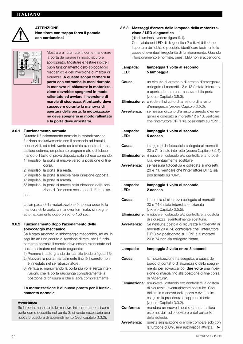
ATTENZIONENon tirare con troppa forza il pomolo con cordoncino!
Mostrare ai futuri utenti come manovrarela porta da garage in modo sicuro eappropriato. Mostrare e testare inoltre ilbuon funzionamento dello sbloccaggiomeccanico e dell'inversione di marcia disicurezza. A questo scopo fermare laporta con entrambe le mani durantela manovra di chiusura: la motorizza-zione dovrebbe spegnersi in modorallentato ed avviare l'inversione dimarcia di sicurezza. Altrettanto devesuccedere durante la manovra diapertura della porta: la motorizzazio-ne deve spegnersi in modo rallentatoe la porta deve arrestarsi.
3.6.1 Funzionamento normaleDurante il funzionamento normale la motorizzazione funziona esclusivamente con il comando ad impulsisequenziali, ed è irrilevante se è stato azionato da unatastiera esterna, un pulsante programmato del teleco-mando o il tasto di prova disposto sulla scheda comando:1° impulso: la porta si muove verso la posizione di fine
corsa.2° impulso: la porta si arresta.3° impulso: la porta si muove nella direzione opposta.4° impulso: la porta si arresta.5° impulso: la porta si muove nella direzione della posi-
zione di fine corsa scelta con il 1° impulso.ecc.
La lampada della motorizzazione è accesa durante lamanovra delle porta; a manovra terminata, si spegneautomaticamente dopo 5 sec. o 150 sec.
3.6.2 Funzionamento dopo l'azionamento dello sbloccaggio meccanicoSe è stato azionato lo sbloccaggio meccanico, ad es. inseguito ad una caduta di tensione di rete, per il funzio-namento normale il carrello deve essere reinnestato nelserratrascinatore nel modo seguente:1) Premere il tasto grande del carrello (vedere figura 16).2) Muovere la porta manualmente finché il carrello non
è innestato nel serratrascinatore .3) Verificare, manovrando la porta più volte senza inter-
ruzioni, che la porta raggiunga completamente laposizione di chiusura e che si apra completamente.
La motorizzazione è di nuovo pronta per il funzio-namento normale.
AvvertenzaSe la porta, nonostante le manovre ininterrotte, non si com-porta come descritto nel punto 3, si rende necessaria unanuova procedura di apprendimento (vedi capitolo 3.3.2).
3.6.3 Messaggi d'errore della lampada della motorizza-zione / LED diagnostica(diodi luminosi, vedere figura 9.1).Con l'aiuto dei LED di diagnostica 2 e 5, visibili dopo l'apertura dell'oblò, è possibile identificare facilmente lecause di eventuali irregolarità di funzionamento. Quandoil funzionamento è normale, questi LED non si accendono.
Lampada: lampeggia 1 volta al secondoLED: 5 lampeggia
Causa: un circuito di arresto o di arresto d'emergenza collegato ai morsetti 12 e 13 è stato interrotto o aperto durante una manovra della porta (vedere Capitolo 3.5.3).
Eliminazione: chiudere il circuito di arresto o di arresto d'emergenza (vedere Capitolo 3.5.3).
Avvertenza: se nessun circuito d'arresto o arresto d'emer-genza è collegato ai morsetti 12 e 13, verificareche l'interruttore DIP 1 sia posizionato su "ON".
Lampada: lampeggia 1 volta al secondoLED: 5 acceso
Causa: il raggio della fotocellula collegata ai morsetti 20 e 71 è stato interrotto (vedere Capitolo 3.5.4).
Eliminazione: rimuovere l'ostacolo e/o controllare la fotocel-lula, eventualmente sostituire.
Avvertenza: se nessuna fotocellula è collegata ai morsetti 20 e 71, verificare che l'interruttore DIP 2 sia posizionato su "ON".
Lampada: lampeggia 1 volta al secondoLED: 2 acceso
Causa: la costola di sicurezza collegata ai morsetti 20 e 74 è stata interrotta o azionata (vedere Capitolo 3.5.5).
Eliminazione: rimuovere l'ostacolo e/o controllare la costola di sicurezza, eventualmente sostituire.
Avvertenza: Se nessuna costola di sicurezza è collegata ai morsetti 20 e 74, controllare che l'interruttore DIP 3 sia posizionato su "ON" e ai morsetti 20 e 74 non sia collegato niente.
Lampada: lampeggia 2 volta entro 3 secondi
Causa: la motorizzazione ha eseguito, a causa del bordo di contatto di sicurezza o dello spegni-mento per sovraccarico, due volte una inver-sione di marcia fino alla posizione di fine corsa di "Apertura".
Eliminazione: rimuovere l'ostacolo e/o controllare la costola di sicurezza, eventualmente sostituire. Con-trollare la manovra della porta e eventualm. eseguire la procedura di apprendimento (vedere Capitolo 3.3.2).
Conferma: mandare un nuovo impulso da una tastiera esterna, dal radioricevitore o dal pulsante della scheda.
Avvertenza: questa segnalazione di errore compare solo conla funzione di Chiusura automatica attivata.
54 01.2004 V1.0 / 401 RE
I TA L I A N O
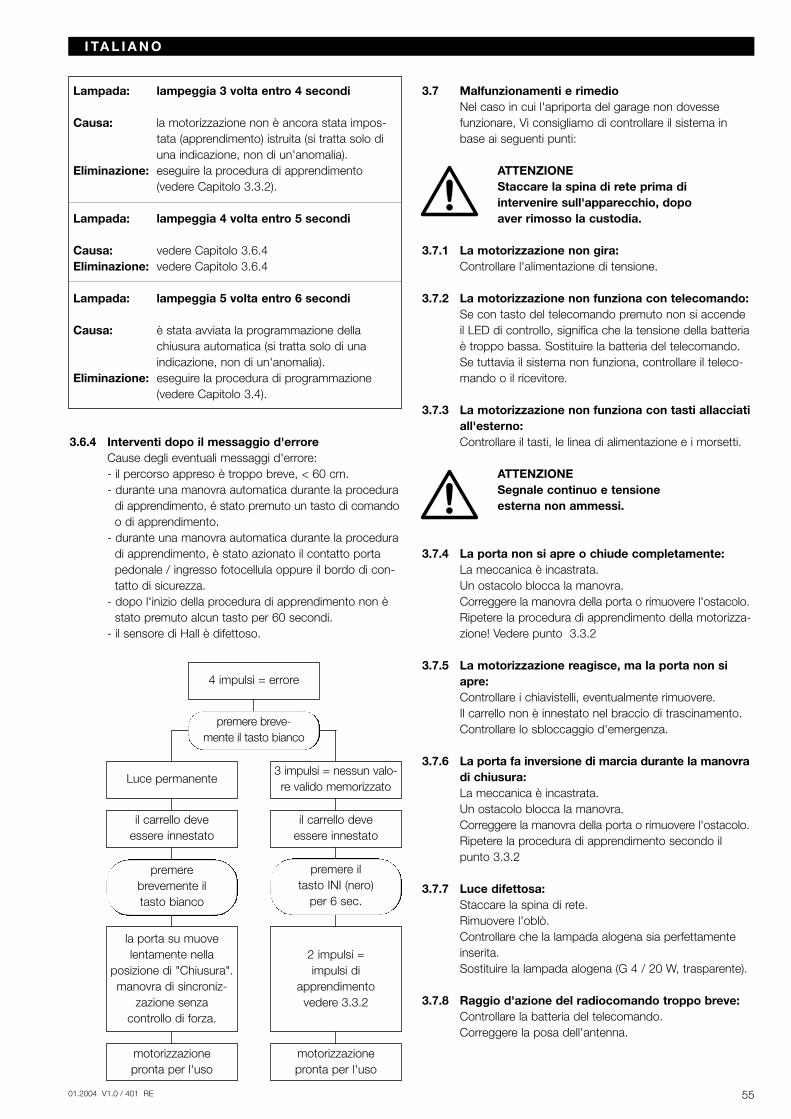
5501.2004 V1.0 / 401 RE
Lampada: lampeggia 3 volta entro 4 secondi
Causa: la motorizzazione non è ancora stata impos-tata (apprendimento) istruita (si tratta solo di una indicazione, non di un'anomalia).
Eliminazione: eseguire la procedura di apprendimento (vedere Capitolo 3.3.2).
Lampada: lampeggia 4 volta entro 5 secondi
Causa: vedere Capitolo 3.6.4Eliminazione: vedere Capitolo 3.6.4
Lampada: lampeggia 5 volta entro 6 secondi
Causa: è stata avviata la programmazione della chiusura automatica (si tratta solo di una indicazione, non di un'anomalia).
Eliminazione: eseguire la procedura di programmazione (vedere Capitolo 3.4).
3.6.4 Interventi dopo il messaggio d'erroreCause degli eventuali messaggi d'errore:- il percorso appreso è troppo breve, < 60 cm.- durante una manovra automatica durante la procedura
di apprendimento, é stato premuto un tasto di comandoo di apprendimento.
- durante una manovra automatica durante la proceduradi apprendimento, è stato azionato il contatto portapedonale / ingresso fotocellula oppure il bordo di con-tatto di sicurezza.
- dopo l'inizio della procedura di apprendimento non èstato premuto alcun tasto per 60 secondi.
- il sensore di Hall è difettoso.
3.7 Malfunzionamenti e rimedioNel caso in cui l'apriporta del garage non dovesse funzionare, Vi consigliamo di controllare il sistema inbase ai seguenti punti:
ATTENZIONEStaccare la spina di rete prima di intervenire sull'apparecchio, dopo aver rimosso la custodia.
3.7.1 La motorizzazione non gira:Controllare l'alimentazione di tensione.
3.7.2 La motorizzazione non funziona con telecomando:Se con tasto del telecomando premuto non si accendeil LED di controllo, significa che la tensione della batteriaè troppo bassa. Sostituire la batteria del telecomando.Se tuttavia il sistema non funziona, controllare il teleco-mando o il ricevitore.
3.7.3 La motorizzazione non funziona con tasti allacciatiall'esterno:Controllare il tasti, le linea di alimentazione e i morsetti.
ATTENZIONESegnale continuo e tensione esterna non ammessi.
3.7.4 La porta non si apre o chiude completamente:La meccanica è incastrata.Un ostacolo blocca la manovra.Correggere la manovra della porta o rimuovere l'ostacolo.Ripetere la procedura di apprendimento della motorizza-zione! Vedere punto 3.3.2
3.7.5 La motorizzazione reagisce, ma la porta non siapre:Controllare i chiavistelli, eventualmente rimuovere.Il carrello non è innestato nel braccio di trascinamento.Controllare lo sbloccaggio d'emergenza.
3.7.6 La porta fa inversione di marcia durante la manovradi chiusura:La meccanica è incastrata.Un ostacolo blocca la manovra.Correggere la manovra della porta o rimuovere l'ostacolo.Ripetere la procedura di apprendimento secondo ilpunto 3.3.2
3.7.7 Luce difettosa:Staccare la spina di rete.Rimuovere l'oblò.Controllare che la lampada alogena sia perfettamenteinserita.Sostituire la lampada alogena (G 4 / 20 W, trasparente).
3.7.8 Raggio d'azione del radiocomando troppo breve:Controllare la batteria del telecomando.Correggere la posa dell'antenna.
I TA L I A N O
Luce permanente
4 impulsi = errore
3 impulsi = nessun valo-re valido memorizzato
il carrello deve essere innestato
il carrello deve essere innestato
la porta su muove lentamente nella
posizione di "Chiusura".manovra di sincroniz-
zazione senza controllo di forza.
2 impulsi = impulsi di
apprendimentovedere 3.3.2
motorizzazione pronta per l'uso
premere il tasto INI (nero)
per 6 sec.
premere brevemente il tasto bianco
motorizzazione pronta per l'uso
premere breve-mente il tasto bianco
4 Garanzia
Durata della garanziaIn aggiunta alla garanzia legale, rilasciata dal rivenditoree risultante dal contratto di vendita, assicuriamo unagaranzia di 24 mesi dalla data d'acquisto. Il ricorso allagaranzia non avrà effetto sulla durata della stessa. Per le forniture di ricambi e i lavori di riparazione il periodo di garanzia è di sei mesi, ovvero almeno il periodo digaranzia iniziale.
CondizioniIl diritto alla garanzia è valido soltanto per il Paese in cuiè stato acquistato il prodotto. La merce deve essere stataacquistata attraverso i canali di vendita da noi stabiliti. Ildiritto alla garanzia può essere fatto valere soltanto perdanni sull'oggetto del contratto. Il rimborso di spese perlo smontaggio, il montaggio, il controllo delle relative particosì come richieste di risarcimento danni o per perditedi utile sono esclusi dalla garanzia. La ricevuta originalecertifica il Suo diritto alla garanzia.
PrestazioniDurante il periodo di garanzia elimineremo qualsiasi difettodel prodotto derivante da un difetto del materiale o dellaproduzione, che deve essere dimostrato. Ci impegniamo,a nostro giudizio, a riparare o a sostituire gratuitamentela merce difettosa con merce esente da vizi oppure acompensare il minor valore.
La garanzia non copre i danni causati da: - installazione e allacciamento impropri- messa in funzione e uso impropri- effetti esterni come fuoco, acqua, condizioni
ambientali anomale- danneggiamenti meccanici provocati da incidenti,
cadute, urti- danneggiamenti dolosi o intenzionali- una normale usura- riparazioni effettuate da persone non qualificate- utilizzo di prodotti di terzi- interventi tendenti ad eliminare o rendere illeggibile
il codice di prodottoLe parti sostituite ritornano ad essere nostra proprietà.
5 Dati tecnici
Alimentazione: 230/240 V, 50/60 HzStandby ca. 1 W
Tipo di protezione: adatta solo per locali asciutti
Spegnimento apprendimento automatico eautomatico: separato per i due sensi di
marcia
Disattivazione fine ad autoapprendimento, esentecorsa/limitatore di da usura perché senza inter-sforzo: ruttori meccanici, inoltre con
limitazione del ciclo di manovra incorporata a ca. 140 sec.;
spegnimento automatico con registrazione successiva ad ogni manovra.
Forza di trazione e di spinta: vedere targhetta
Motore: motore a corrente continua consensore di Hall
Trasformatore: con termointerruttore
Collegamenti: tecnica esente da viti per appa-recchi esterni con bassa tensionedi sicurezza inferiore a 24 V DC,come ad es. tastiera esterna o interna con funzionamento ad impulsi.
Funzioni speciali: - illuminazione della moto-rizzazione
- interruttore stop/spento collegabile
- fotocellula e costola di sicurezza collegabili
- lampada d'emergenza da 230 V AC collegabile
- relè opzionale per illumina-zione esterna collegabile
Sbloccaggio rapido: in mancanza di corrente, da azionare dall'interno con cordoncino
Comando a distanza: telecomando a 4 pulsanti RC BE 868/4 (868,360 MHz) e ricevitore separato
Accessori universali: per porte basculanti e portoni sezionali
Velocità di ca. 135 mm/s (a seconda delleapertura/chiusura: dimensioni e del peso della porta)
Emissione di suono nell'ariaMotorizzazione: ≤ 70 dB (A)
Guida di traino da 30 mm, estremamenteportante: piatta. Con sicurezza antintru-
sione incorporata. Guida in versione con cinghia dentata o con catena.
6 Smontaggio e smaltimentoIn caso di smontaggio, rispettare le direttive in materia di sicurezza. Lo smaltimento deve essere effettuato nellerispetto delle relative disposizioni vigenti.
Con riserva di modifiche tecniche!Stampa: settembre 2003
56 01.2004 V1.0 / 401 RE
I TA L I A N O

5701.2004 V1.0 / 401 RE

01.2004 V1.0 / 401 RE
01.2
004
V1.
0 /
401
RE