Embed Size (px)
DESCRIPTION
Aphex Plug-Ins Guide
Citation preview
Aphex Aural Exciter® Type III andBig Bottom ProPlug-Ins Guide
Version 9.0
Legal Notices
This guide is copyrighted ©2010 by Avid Technology, Inc., (hereafter “Avid”), with all rights reserved. Under copyright laws, this guide may not be duplicated in whole or in part without the written consent of Avid.
003, 96 I/O, 96i I/O, 192 Digital I/O, 192 I/O, 888|24 I/O, 882|20 I/O, 1622 I/O, 24-Bit ADAT Bridge I/O, AudioSuite, Avid, Avid DNA, Avid Mojo, Avid Unity, Avid Unity ISIS, Avid Xpress, AVoption, Axiom, Beat Detective, Bomb Factory, Bruno, C|24, Command|8, Control|24, D-Command, D-Control, D-Fi, D-fx, D-Show, D-Verb, DAE, Digi 002, DigiBase, DigiDelivery, Digidesign, Digidesign Audio Engine, Digidesign Intelligent Noise Reduction, Digidesign TDM Bus, DigiDrive, DigiRack, DigiTest, DigiTranslator, DINR, DV Toolkit, EditPack, Eleven, EUCON, HD Core, HD Process, Hybrid, Impact, Interplay, LoFi, M-Audio, MachineControl, Maxim, Mbox, MediaComposer, MIDI I/O, MIX, MultiShell, Nitris, OMF, OMF Interchange, PRE, ProControl, Pro Tools M-Powered, Pro Tools, Pro Tools|HD, Pro Tools LE, QuickPunch, Recti-Fi, Reel Tape, Reso, Reverb One, ReVibe, RTAS, Sibelius, Smack!, SoundReplacer, Sound Designer II, Strike, Structure, SYNC HD, SYNC I/O, Synchronic, TL Aggro, TL AutoPan, TL Drum Rehab, TL Everyphase, TL Fauxlder, TL In Tune, TL MasterMeter, TL Metro, TL Space, TL Utilities, Transfuser, Trillium Lane Labs, Vari-Fi, Velvet, X-Form, and XMON are trademarks or registered trademarks of Avid Technology, Inc. Xpand! is Registered in the U.S. Patent and Trademark Office. All other trademarks are the property of their respective owners.
Product features, specifications, system requirements, and availability are subject to change without notice.
Guide Part Number 9329-65043-00 REV A 9/10
Documentation Feedback
At Avid, we are always looking for ways to improve our documentation. If you have comments, corrections, or suggestions regarding our documentation, email us at [email protected].
contents
Chapter 1. Introduction . . . . . . . . . . . . . . . . . . . . . . . . . . . . . . . . . . . . . . . . . . . . . . . . . . . . . . 1
Contents of the Boxed Version of Your Plug-In . . . . . . . . . . . . . . . . . . . . . . . . . . . . . . . . . . . . 1
System Requirements and Compatibility . . . . . . . . . . . . . . . . . . . . . . . . . . . . . . . . . . . . . . . . 1
Registering Plug-Ins. . . . . . . . . . . . . . . . . . . . . . . . . . . . . . . . . . . . . . . . . . . . . . . . . . . . . . . 2
Working with Plug-Ins . . . . . . . . . . . . . . . . . . . . . . . . . . . . . . . . . . . . . . . . . . . . . . . . . . . . . 2
Conventions Used in This Guide . . . . . . . . . . . . . . . . . . . . . . . . . . . . . . . . . . . . . . . . . . . . . . 2
About www.avid.com . . . . . . . . . . . . . . . . . . . . . . . . . . . . . . . . . . . . . . . . . . . . . . . . . . . . . . 3
Chapter 2. Installation and Authorization . . . . . . . . . . . . . . . . . . . . . . . . . . . . . . . . . . . . . . 5
Installing Plug-Ins for Pro Tools. . . . . . . . . . . . . . . . . . . . . . . . . . . . . . . . . . . . . . . . . . . . . . . 5
Authorizing Plug-Ins. . . . . . . . . . . . . . . . . . . . . . . . . . . . . . . . . . . . . . . . . . . . . . . . . . . . . . . 5
Removing Plug-Ins . . . . . . . . . . . . . . . . . . . . . . . . . . . . . . . . . . . . . . . . . . . . . . . . . . . . . . . 6
Chapter 3. Aural Exciter Controls . . . . . . . . . . . . . . . . . . . . . . . . . . . . . . . . . . . . . . . . . . . . . 7
Aphex Aural Exciter Type III Overview . . . . . . . . . . . . . . . . . . . . . . . . . . . . . . . . . . . . . . . . . . 7
Adjusting Plug-In Controls . . . . . . . . . . . . . . . . . . . . . . . . . . . . . . . . . . . . . . . . . . . . . . . . . . 8
Meters . . . . . . . . . . . . . . . . . . . . . . . . . . . . . . . . . . . . . . . . . . . . . . . . . . . . . . . . . . . . . . . . 9
Rotary Controls . . . . . . . . . . . . . . . . . . . . . . . . . . . . . . . . . . . . . . . . . . . . . . . . . . . . . . . . . 10
Switches . . . . . . . . . . . . . . . . . . . . . . . . . . . . . . . . . . . . . . . . . . . . . . . . . . . . . . . . . . . . . 13
Chapter 4. Using Aural Exciter III . . . . . . . . . . . . . . . . . . . . . . . . . . . . . . . . . . . . . . . . . . . . 15
Inserting Aural Exciter on a Track . . . . . . . . . . . . . . . . . . . . . . . . . . . . . . . . . . . . . . . . . . . . 15
Setting the Gain Structure . . . . . . . . . . . . . . . . . . . . . . . . . . . . . . . . . . . . . . . . . . . . . . . . . 15
Information on Clipping . . . . . . . . . . . . . . . . . . . . . . . . . . . . . . . . . . . . . . . . . . . . . . . . . . . 16
Using the Tune Fader. . . . . . . . . . . . . . . . . . . . . . . . . . . . . . . . . . . . . . . . . . . . . . . . . . . . . 17
Using the SPR Switch . . . . . . . . . . . . . . . . . . . . . . . . . . . . . . . . . . . . . . . . . . . . . . . . . . . . 17
Using Aural Exciter on 176.4 kHz or 192 kHz Stereo Tracks . . . . . . . . . . . . . . . . . . . . . . . . . 18
Contents iii
iv
Chapter 5. Big Bottom Pro Controls. . . . . . . . . . . . . . . . . . . . . . . . . . . . . . . . . . . . . . . . . . 19
Aphex Big Bottom Overview. . . . . . . . . . . . . . . . . . . . . . . . . . . . . . . . . . . . . . . . . . . . . . . . 19
Adjusting Plug-In Parameters . . . . . . . . . . . . . . . . . . . . . . . . . . . . . . . . . . . . . . . . . . . . . . 20
Meters . . . . . . . . . . . . . . . . . . . . . . . . . . . . . . . . . . . . . . . . . . . . . . . . . . . . . . . . . . . . . . 21
Rotary Controls . . . . . . . . . . . . . . . . . . . . . . . . . . . . . . . . . . . . . . . . . . . . . . . . . . . . . . . . 22
Switches . . . . . . . . . . . . . . . . . . . . . . . . . . . . . . . . . . . . . . . . . . . . . . . . . . . . . . . . . . . . . 23
Chapter 6. Using Big Bottom Pro . . . . . . . . . . . . . . . . . . . . . . . . . . . . . . . . . . . . . . . . . . . . 25
Inserting Big Bottom Pro on a Track . . . . . . . . . . . . . . . . . . . . . . . . . . . . . . . . . . . . . . . . . . 25
Setting the Gain Structure . . . . . . . . . . . . . . . . . . . . . . . . . . . . . . . . . . . . . . . . . . . . . . . . . 25
Optimizing Big Bottom Pro Effects . . . . . . . . . . . . . . . . . . . . . . . . . . . . . . . . . . . . . . . . . . . 25
Appendix A. DSP Requirements. . . . . . . . . . . . . . . . . . . . . . . . . . . . . . . . . . . . . . . . . . . . . . 27
Aphex Aural Exciter and Big Bottom DSP Requirements . . . . . . . . . . . . . . . . . . . . . . . . . . . . 28
Appendix B. DSP Delays Incurred by TDM Plug-Ins . . . . . . . . . . . . . . . . . . . . . . . . . . . . 29
Aphex Aural Exciter and Big Bottom DSP Delay . . . . . . . . . . . . . . . . . . . . . . . . . . . . . . . . . . 29
Index . . . . . . . . . . . . . . . . . . . . . . . . . . . . . . . . . . . . . . . . . . . . . . . . . . . . . . . . . . . . . . . . . . . . . 30
Aphex Aural Exciter Type III and Big Bottom Pro Plug-Ins Guide
chapter 1
Introduction
The Aural Exciter® Type III and Big Bottom Pro plug-ins are real-time TDM plug-ins that retain the look and sound of Aphex Systems’ renowned hardware units. Aural Exciter makes it possible to recreate and restore missing harmonics.
The Aural Exciter Type III and Big Bottom Pro plug-ins provide support for 44.1 kHz, 48 kHz, 88.2 kHz, 96 kHz, 176.4 kHz, and 192 kHz sessions.
Contents of the Boxed Version of Your Plug-InYour Aphex Aural Exciter Type III and Big Bot-tom Pro plug-in boxed version contains the fol-lowing components:
• Installation disc
• Activation Card with an Activation Code
On 176.4 kHz or 192 kHz stereo tracks, Aural Exciter is only available as a multi-mono plug-in.
System Requirements and Compatibility
To use Aural Exciter III and Big Bottom Pro, you need:
• An iLok USB Smart Key
• An iLok.com account for managing iLok li-censes
• One of the following:
• A qualified Pro Tools|HD® system or Pro Tools|HD Accel system
– or –
• A qualified VENUE™ system
Avid can only assure compatibility and provide support for hardware and software it has tested and approved.
For complete system requirements and a list of qualified computers, operating systems, hard drives, and third-party devices, visit:
www.avid.com/compatibility
Chapter 1: Introduction 1
2
Registering Plug-InsYour plug-in purchase is automatically regis-tered when you activate your iLok license (see “Authorizing Plug-Ins” on page 5).
Registered users are eligible to receive software update and upgrade notices.
For information on technical support, visit www.avid.com.
Working with Plug-InsBesides the information provided in this guide, refer to the Pro Tools Reference Guide for general information on working with plug-ins, includ-ing:
• Inserting plug-ins on tracks
• Using clip indicators
• Navigating the Plug-In window
• Adjusting plug-in controls
• Automating plug-ins
• Using plug-in presets
Aphex Aural Exciter Type III and Big Bottom Pro Plug-Ins
Conventions Used in This GuideAll Pro Tools guides use the following conven-tions to indicate menu choices and key commands::
The names of Commands, Options, and Settings that appear on-screen are in a different font.
The following symbols are used to highlight important information:
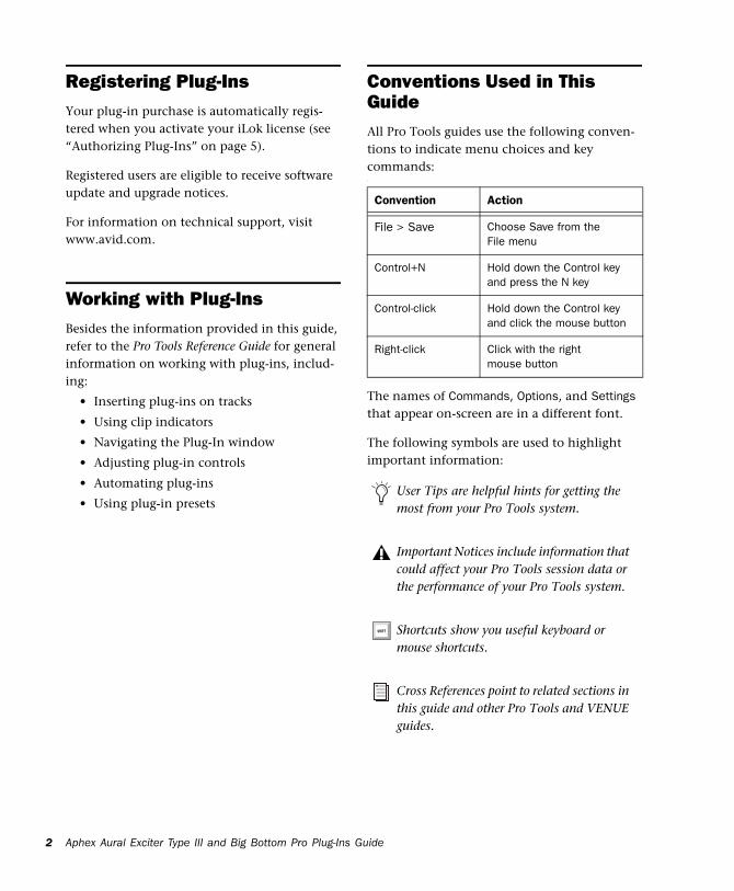
Convention Action
File > Save Choose Save from the File menu
Control+N Hold down the Control key and press the N key
Control-click Hold down the Control key and click the mouse button
Right-click Click with the right mouse button
User Tips are helpful hints for getting the most from your Pro Tools system.
Important Notices include information that could affect your Pro Tools session data or the performance of your Pro Tools system.
Shortcuts show you useful keyboard or mouse shortcuts.
Cross References point to related sections in this guide and other Pro Tools and VENUE guides.
Guide
About www.avid.comThe Avid website (www.avid.com) is your best online source for information to help you get the most out of your Pro Tools system. The fol-lowing are just a few of the services and features available.
Product Registration Register your purchase online.
Support and Downloads Contact Avid Customer Success (technical support); download software updates and the latest online manuals; browse the Compatibility documents for system re-quirements; search the online Knowledge Base or join the worldwide Pro Tools community on the User Conference.
Training and Education Study on your own using courses available online or find out how you can learn in a classroom setting at a certified Pro Tools training center.
Products and Developers Learn about Avid products; download demo software or learn about our Development Partners and their plug-ins, applications, and hardware.
News and Events Get the latest news from Avid or sign up for a Pro Tools demo.
Chapter 1: Introduction 3

4
Aphex Aural Exciter Type III and Big Bottom Pro Plug-Ins Guide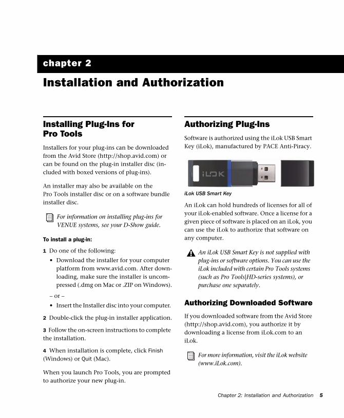
chapter 2
Installation and Authorization
Installing Plug-Ins for Pro ToolsInstallers for your plug-ins can be downloaded from the Avid Store (http://shop.avid.com) or can be found on the plug-in installer disc (in-cluded with boxed versions of plug-ins).
An installer may also be available on the Pro Tools installer disc or on a software bundle installer disc.
To install a plug-in:
1 Do one of the following:
• Download the installer for your computer platform from www.avid.com. After down-loading, make sure the installer is uncom-pressed (.dmg on Mac or .ZIP on Windows).
– or –
• Insert the Installer disc into your computer.
2 Double-click the plug-in installer application.
3 Follow the on-screen instructions to complete the installation.
4 When installation is complete, click Finish (Windows) or Quit (Mac).
When you launch Pro Tools, you are prompted to authorize your new plug-in.
For information on installing plug-ins for VENUE systems, see your D-Show guide.
Authorizing Plug-InsSoftware is authorized using the iLok USB Smart Key (iLok), manufactured by PACE Anti-Piracy.
An iLok can hold hundreds of licenses for all of your iLok-enabled software. Once a license for a given piece of software is placed on an iLok, you can use the iLok to authorize that software on any computer.
Authorizing Downloaded Software
If you downloaded software from the Avid Store (http://shop.avid.com), you authorize it by downloading a license from iLok.com to an iLok.
iLok USB Smart Key
An iLok USB Smart Key is not supplied with plug-ins or software options. You can use the iLok included with certain Pro Tools systems (such as Pro Tools|HD-series systems), or purchase one separately.
For more information, visit the iLok website (www.iLok.com).
Chapter 2: Installation and Authorization 5
6
Authorizing Boxed Versions of Software
If you purchased a boxed version of software, it comes with an Activation Code (on the included Activation Card).
To authorize software using an Activation Code:
1 If you do not have an iLok.com account, visit www.iLok.com and sign up for an account.
2 Transfer the license for your software to your iLok.com account by doing the following:
• Visit www.avid.com/activation.
– and –
• Input your Activation Code (listed on your Activation Card) and your iLok.com User ID. Your iLok.com User ID is the name you create for your iLok.com account.
3 Transfer the licenses from your iLok.com ac-count to your iLok USB Smart Key by doing the following:
• Insert the iLok into an available USB port on your computer.
• Go to www.iLok.com and log in.
• Follow the on-screen instructions for trans-ferring your licences to your iLok.
4 Launch Pro Tools.
5 If you have any unauthorized software installed, you are prompted to authorize it.Follow the on-screen instructions to complete the authorization process.
For more information, visit the iLok website (www.iLok.com).
Aphex Aural Exciter Type III and Big Bottom Pro Plug-Ins
Removing Plug-InsIf you need to remove a plug-in from your Pro Tools system, follow the instructions below for your computer platform.
Mac OS X
To remove a plug-in:
1 Locate and open the Plug-Ins folder on your Startup drive (Library/Application Support/Digidesign/Plug-Ins).
2 Do one of the following:
• Drag the plug-in to the Trash and empty the Trash.
– or –
• Drag the plug-in to the Plug-Ins (Unused) folder.
Windows
To remove a plug-in:
1 Choose Start > Control Panel.
2 Under Programs, click Uninstall a program.
3 Select the plug-in from the list of installed ap-plications.
4 Click Uninstall.
5 Follow the on-screen instructions to remove the plug-in.
Guide
chapter 3
Aural Exciter Controls
Aphex Aural Exciter Type III OverviewAphex Systems, Inc. first introduced Aural Ex-citer in 1975. Since then, several refinements and improvements have been incorporated into its original design. The Aural Exciter plug-in is modeled after the TYPE III Aural Exciter. Aural Exciter has become a standard in the profes-sional audio industry, and has been used on many albums, CDs, movies, broadcast produc-tions, commercials, and concerts. The Aural Ex-citer plug-in for Pro Tools TDM systems contin-ues this tradition of success, and is ready for use with the latest cutting edge music productions.
Harmonics are musically and dynamically re-lated to the original sound, and reveal the fine differences between voices and various instru-ments. Reproduced sound is audibly different from the original live sound because of the loss in harmonic detail, often sounding dull and life-less.
Aural Exciter is an audio process that recreates and restores missing harmonics. It actually adds harmonics, restoring the sound’s natural bright-ness, clarity and presence, effectively improving detail and intelligibility. Use Aural Exciter on specific instruments or in the final mix to bring life back to recordings.
Unlike EQs and other brightness enhancers which only boost the high frequencies that of-ten alter the overall tonal balance, Aural Exciter extends the high frequencies. The stereo image is enhanced with Aural Exciter. This results in a greater perceived loudness without an introduc-tion of noise into the audio path, commonly caused by increased gain.
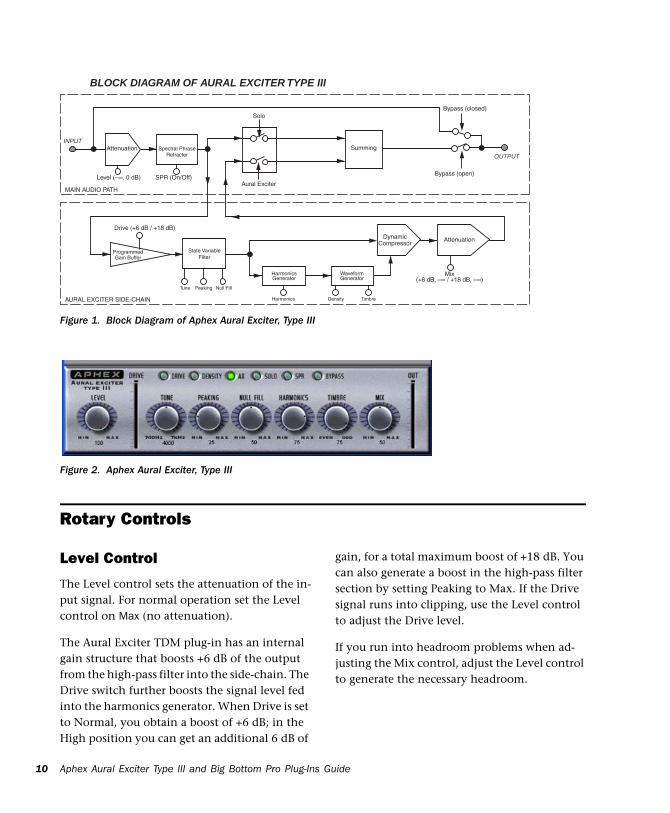
Aural Exciter is a single-ended process which can be inserted at any point within the audio chain (see Figure 1 on page 10). The input signal is split into two paths. One path goes to the out-put unmodified, while the other path, known as a side-chain, goes through the Aural Exciter, which includes a tunable high-pass filter and a harmonics generator. Aural Exciter applies fre-quency-dependent phase shift and amplitude-dependent harmonics. The output of the Aural Exciter's harmonic generator is mixed back with the unmodified signal, lower in level.
When used at nominal settings, Aural Exciter does not add significant average level to the original signal. Even though the added informa-tion is low level, the perception is a dramatic in-crease in mid and high frequencies.
Chapter 3: Aural Exciter Controls 7
8
The Aural Exciter is patented in the United States, Japan and most of Europe. Others may claim they are doing the same thing, but they can only resort to some form of EQ (amplitude correction or expansion), phase scrambling and/or filtering. They can only increase peak levels causing clipping, feedback, tape distortion and listener fatigue.
Adjusting Plug-In ControlsYou can adjust plug-in controls by dragging the control’s slider or knob, or by typing a value into the control’s text box. Additionally, some plug-ins have switches that can be enabled by click-ing on them.
To adjust a plug-in control:
1 Begin audio playback so that you can hear the control changes in real time.
2 Adjust the controls of the plug-in for the effect you want. Refer to “Editing Parameters Using a Mouse” on page 8 and “Editing Parameters Us-ing a Computer Keyboard” on page 8.
Closing the plug-in will save the most recent changes.
Aphex Aural Exciter Type III and Big Bottom Pro Plug-Ins
Editing Parameters Using a Mouse
You can adjust rotary controls by dragging hori-zontally or vertically. Parameter values increase as you drag upward or to the right, and decrease as you drag downward or to the left.
Keyboard Shortcuts
For finer adjustments, Control-drag (Win-dows) or Command-drag (Mac) the control.
To return a control to its default value, Alt-click (Windows) or Option-click (Mac) the con-trol.
Editing Parameters Using a Computer Keyboard
Some controls have text boxes that display the current value of the parameter. You can edit the numeric value of a parameter with your com-puter keyboard.
If multiple Plug-In windows are open, Tab and keyboard entry remain focused on the plug-in that is the target window.
To change control values with a computer keyboard:
1 Click the text box corresponding to the con-trol that you want to adjust.
2 Change the value.
• To increase a value, press the Up Arrow on your keyboard. To decrease a value, press the Down Arrow on your keyboard.
– or –
• Type the desired value.
In fields that support values in kilohertz, typing “k” after a number value will multi-ply the value by 1,000. For example, type “8k” to enter a value of 8,000.
Guide
3 Do one of the following:
• Press Enter on the numeric keyboard to in-put the value and remain in keyboard edit-ing mode.
– or –
• Press Enter on the alpha keyboard (Win-dows) or Return (Mac) to enter the value and leave keyboard editing mode.
Editing Parameters Using a Scroll Wheel
Some controls have text boxes that display the current value of the parameter. You can edit the numeric value of a parameter using a scroll wheel.
To change control values using a scroll wheel:
1 Click the text box corresponding to the con-trol that you want to adjust.
2 To increase a value, scroll up with the scroll wheel. To decrease a value, scroll down with the scroll wheel.
Toggling Switches
To toggle a switch:
Click the switch.
To move forward through the different con-trol fields, press the Tab key. To move back-ward, press Shift+Tab.
Meters
Drive Meter
The Drive meter monitors the peak level to the harmonic generator. It works in conjunction with the Drive switch. A red LED at the top of the meter indicates if there is clipping.
For optimal performance keep the peak hold meter of the Drive meter inside the yellow area. The harder you drive the Exciter, the more Ex-citer enhancement you generate. If you cannot get the Drive meter to register in the yellow area, try setting the Drive switch to High (Drive switch enabled).
Out Meter
The Out meter lets you monitor the output level after Aural Exciter processing. A red light at the top of the meter indicates if there is clipping.
The Plug-In window header includes a Clip LED that lights red to indicate plug-in clip-ping. The Plug-In Clip LED follows Pro Tools settings for clip indication. (For more information, see the Pro Tools Refer-ence Guide.)
If your input material has a peak level, be careful to prevent clipping when setting the Mix control.
Chapter 3: Aural Exciter Controls 9
10
Aphex Aural Exciter Type III and Big Bottom Pro Plug-InsFigure 1. Block Diagram of Aphex Aural Exciter, Type III
BLOCK DIAGRAM OF AURAL EXCITER TYPE III
INPUTAttenuation
Mix�(+6 dB, –∞ / +18 dB, –∞)
Peaking
Programmed�Gain Buffer
Solo
Aural ExciterLevel (–∞, 0 dB) SPR (On/Off)
Drive (+6 dB / +18 dB)
MAIN AUDIO PATH
AURAL EXCITER SIDE-CHAIN
Summing
Bypass (closed)
Bypass (open)
Tune Null FIll
AttenuationDynamic�Compressor
OUTPUTSpectral Phrase�
Refracter
State Variable�Filter
Harmonics
Harmonics�Generator
Density Timbre
Waveform�Generator
Rotary Controls
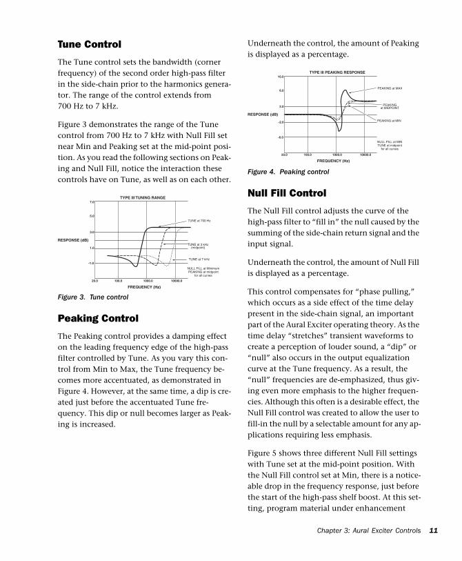
Figure 2. Aphex Aural Exciter, Type III
Level Control
The Level control sets the attenuation of the in-put signal. For normal operation set the Level control on Max (no attenuation).
The Aural Exciter TDM plug-in has an internal gain structure that boosts +6 dB of the output from the high-pass filter into the side-chain. The Drive switch further boosts the signal level fed into the harmonics generator. When Drive is set to Normal, you obtain a boost of +6 dB; in the High position you can get an additional 6 dB of
gain, for a total maximum boost of +18 dB. You can also generate a boost in the high-pass filter section by setting Peaking to Max. If the Drive signal runs into clipping, use the Level control to adjust the Drive level.
If you run into headroom problems when ad-justing the Mix control, adjust the Level control to generate the necessary headroom.
Guide
Tune Control
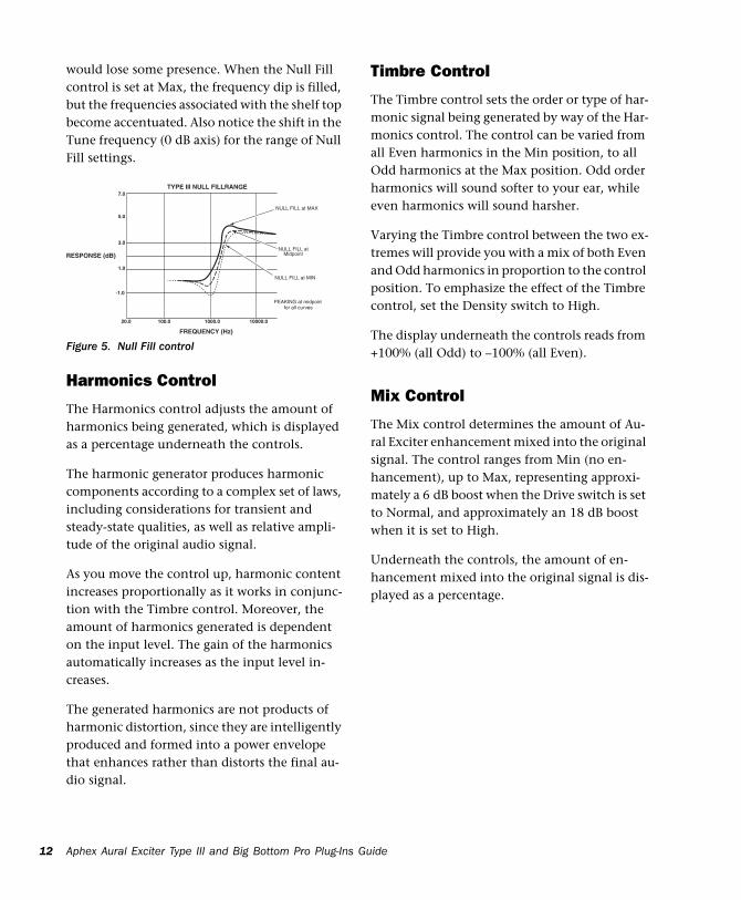
The Tune control sets the bandwidth (corner frequency) of the second order high-pass filter in the side-chain prior to the harmonics genera-tor. The range of the control extends from 700 Hz to 7 kHz.
Figure 3 demonstrates the range of the Tune control from 700 Hz to 7 kHz with Null Fill set near Min and Peaking set at the mid-point posi-tion. As you read the following sections on Peak-ing and Null Fill, notice the interaction these controls have on Tune, as well as on each other.
Peaking Control
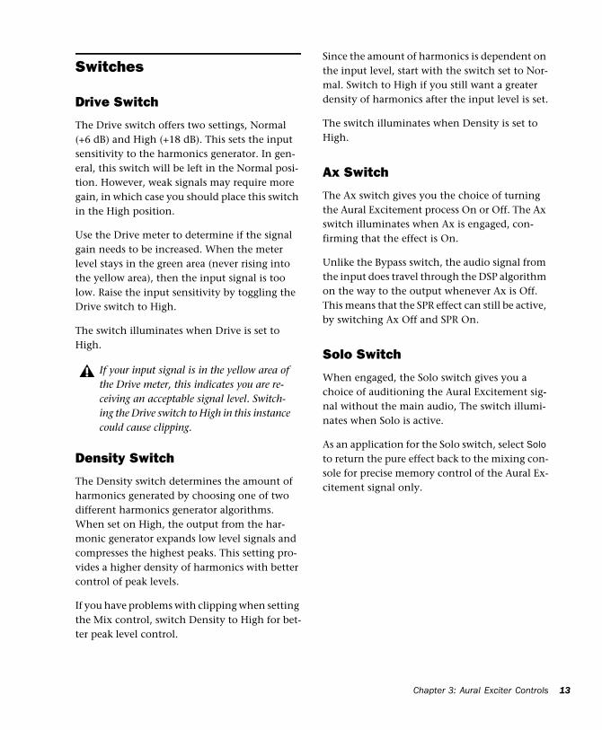
The Peaking control provides a damping effect on the leading frequency edge of the high-pass filter controlled by Tune. As you vary this con-trol from Min to Max, the Tune frequency be-comes more accentuated, as demonstrated in Figure 4. However, at the same time, a dip is cre-ated just before the accentuated Tune fre-quency. This dip or null becomes larger as Peak-ing is increased.
Figure 3. Tune control
TYPE III TUNING RANGE
RESPONSE (dB)
FREQUENCY (Hz)
7.0
5.0
3.0
1.0
-1.0
20.0 100.0 1000.0 10000.0
TUNE at 700 Hz
TUNE at 7 kHz
NULL FILL at MinimumPEAKING at midpoint�
for all curves
TUNE at 3 kHz�(midpoint)
Underneath the control, the amount of Peaking is displayed as a percentage.
Null Fill Control
The Null Fill control adjusts the curve of the high-pass filter to “fill in” the null caused by the summing of the side-chain return signal and the input signal.
Underneath the control, the amount of Null Fill is displayed as a percentage.
This control compensates for “phase pulling,” which occurs as a side effect of the time delay present in the side-chain signal, an important part of the Aural Exciter operating theory. As the time delay “stretches” transient waveforms to create a perception of louder sound, a “dip” or “null” also occurs in the output equalization curve at the Tune frequency. As a result, the “null” frequencies are de-emphasized, thus giv-ing even more emphasis to the higher frequen-cies. Although this often is a desirable effect, the Null Fill control was created to allow the user to fill-in the null by a selectable amount for any ap-plications requiring less emphasis.
Figure 5 shows three different Null Fill settings with Tune set at the mid-point position. With the Null Fill control set at Min, there is a notice-able drop in the frequency response, just before the start of the high-pass shelf boost. At this set-ting, program material under enhancement
Figure 4. Peaking control
TYPE III PEAKING RESPONSE
RESPONSE (dB)
FREQUENCY (Hz)
10.0
6.0
2.0
-2.0
-6.0
20.0 100.0 1000.0 10000.0
PEAKING at MAX
NULL FILL at MIN�TUNE at midpoint�
for all curves
PEAKING at MIN
PEAKING�at MIDPOINT
�
Chapter 3: Aural Exciter Controls 11
12
would lose some presence. When the Null Fill control is set at Max, the frequency dip is filled, but the frequencies associated with the shelf top become accentuated. Also notice the shift in the Tune frequency (0 dB axis) for the range of Null Fill settings.
Harmonics Control
The Harmonics control adjusts the amount of harmonics being generated, which is displayed as a percentage underneath the controls.
The harmonic generator produces harmonic components according to a complex set of laws, including considerations for transient and steady-state qualities, as well as relative ampli-tude of the original audio signal.
As you move the control up, harmonic content increases proportionally as it works in conjunc-tion with the Timbre control. Moreover, the amount of harmonics generated is dependent on the input level. The gain of the harmonics automatically increases as the input level in-creases.
The generated harmonics are not products of harmonic distortion, since they are intelligently produced and formed into a power envelope that enhances rather than distorts the final au-dio signal.
Figure 5. Null Fill control
TYPE III NULL FILLRANGE
RESPONSE (dB)
FREQUENCY (Hz)
7.0
5.0
3.0
1.0
-1.0
20.0 100.0 1000.0 10000.0
PEAKING at midpoint�for all curves
NULL FILL at MAX
NULL FILL at�Midpoint
NULL FILL at MIN
Aphex Aural Exciter Type III and Big Bottom Pro Plug-Ins
Timbre Control
The Timbre control sets the order or type of har-monic signal being generated by way of the Har-monics control. The control can be varied from all Even harmonics in the Min position, to all Odd harmonics at the Max position. Odd order harmonics will sound softer to your ear, while even harmonics will sound harsher.
Varying the Timbre control between the two ex-tremes will provide you with a mix of both Even and Odd harmonics in proportion to the control position. To emphasize the effect of the Timbre control, set the Density switch to High.
The display underneath the controls reads from +100% (all Odd) to –100% (all Even).
Mix Control
The Mix control determines the amount of Au-ral Exciter enhancement mixed into the original signal. The control ranges from Min (no en-hancement), up to Max, representing approxi-mately a 6 dB boost when the Drive switch is set to Normal, and approximately an 18 dB boost when it is set to High.
Underneath the controls, the amount of en-hancement mixed into the original signal is dis-played as a percentage.
Guide
Switches
Drive Switch
The Drive switch offers two settings, Normal (+6 dB) and High (+18 dB). This sets the input sensitivity to the harmonics generator. In gen-eral, this switch will be left in the Normal posi-tion. However, weak signals may require more gain, in which case you should place this switch in the High position.
Use the Drive meter to determine if the signal gain needs to be increased. When the meter level stays in the green area (never rising into the yellow area), then the input signal is too low. Raise the input sensitivity by toggling the Drive switch to High.
The switch illuminates when Drive is set to High.
Density Switch
The Density switch determines the amount of harmonics generated by choosing one of two different harmonics generator algorithms. When set on High, the output from the har-monic generator expands low level signals and compresses the highest peaks. This setting pro-vides a higher density of harmonics with better control of peak levels.
If you have problems with clipping when setting the Mix control, switch Density to High for bet-ter peak level control.
If your input signal is in the yellow area of the Drive meter, this indicates you are re-ceiving an acceptable signal level. Switch-ing the Drive switch to High in this instance could cause clipping.
Since the amount of harmonics is dependent on the input level, start with the switch set to Nor-mal. Switch to High if you still want a greater density of harmonics after the input level is set.
The switch illuminates when Density is set to High.
Ax Switch
The Ax switch gives you the choice of turning the Aural Excitement process On or Off. The Ax switch illuminates when Ax is engaged, con-firming that the effect is On.
Unlike the Bypass switch, the audio signal from the input does travel through the DSP algorithm on the way to the output whenever Ax is Off. This means that the SPR effect can still be active, by switching Ax Off and SPR On.
Solo Switch
When engaged, the Solo switch gives you a choice of auditioning the Aural Excitement sig-nal without the main audio, The switch illumi-nates when Solo is active.
As an application for the Solo switch, select Solo to return the pure effect back to the mixing con-sole for precise memory control of the Aural Ex-citement signal only.
Chapter 3: Aural Exciter Controls 13
14
SPR Switch
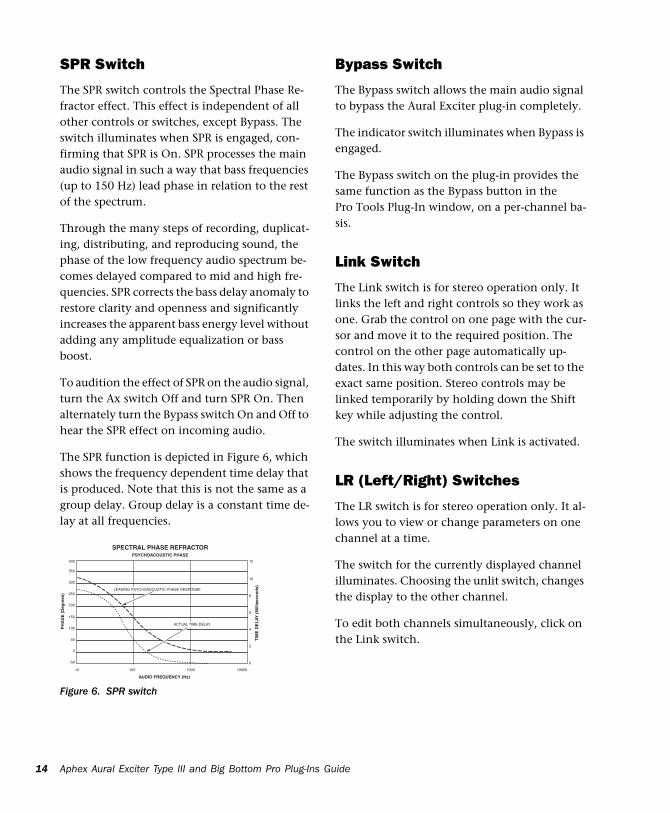
The SPR switch controls the Spectral Phase Re-fractor effect. This effect is independent of all other controls or switches, except Bypass. The switch illuminates when SPR is engaged, con-firming that SPR is On. SPR processes the main audio signal in such a way that bass frequencies (up to 150 Hz) lead phase in relation to the rest of the spectrum.
Through the many steps of recording, duplicat-ing, distributing, and reproducing sound, the phase of the low frequency audio spectrum be-comes delayed compared to mid and high fre-quencies. SPR corrects the bass delay anomaly to restore clarity and openness and significantly increases the apparent bass energy level without adding any amplitude equalization or bass boost.
To audition the effect of SPR on the audio signal, turn the Ax switch Off and turn SPR On. Then alternately turn the Bypass switch On and Off to hear the SPR effect on incoming audio.
The SPR function is depicted in Figure 6, which shows the frequency dependent time delay that is produced. Note that this is not the same as a group delay. Group delay is a constant time de-lay at all frequencies.
Figure 6. SPR switch
SPECTRAL PHASE REFRACTOR
PH
AS
E (
Deg
rees
)
TIM
E D
EL
AY
(M
illis
eco
nd
s)
AUDIO FREQUENCY (Hz)
PSYCHOACOUSTIC PHASE400
350
300
250
200
150
100
50
0
-50
10 100 1000 10000
12
0
2
4
6
8
10
LEADING PSYCHOACOUSTIC PHASE RESPONSE
ACTUAL TIME DELAY
Aphex Aural Exciter Type III and Big Bottom Pro Plug-Ins
Bypass Switch
The Bypass switch allows the main audio signal to bypass the Aural Exciter plug-in completely.
The indicator switch illuminates when Bypass is engaged.
The Bypass switch on the plug-in provides the same function as the Bypass button in the Pro Tools Plug-In window, on a per-channel ba-sis.
Link Switch
The Link switch is for stereo operation only. It links the left and right controls so they work as one. Grab the control on one page with the cur-sor and move it to the required position. The control on the other page automatically up-dates. In this way both controls can be set to the exact same position. Stereo controls may be linked temporarily by holding down the Shift key while adjusting the control.
The switch illuminates when Link is activated.
LR (Left/Right) Switches
The LR switch is for stereo operation only. It al-lows you to view or change parameters on one channel at a time.
The switch for the currently displayed channel illuminates. Choosing the unlit switch, changes the display to the other channel.
To edit both channels simultaneously, click on the Link switch.
Guide
chapter 4
Using Aural Exciter III
In the recording studio, post production suite, or similar environment, post-processing of pre-viously recorded audio tracks with Aural Exciter can restore lost vibrance and realism, even to the extent of saving dialogue or sound effects which were thought to be unusable. Instru-ments and vocals can be made to stand out in the mix without substantially increasing the mix levels or using equalization.
The TDM mixing environment is very flexible, offering several ways to route and use Aural Ex-citer in a session. This section provides some suggestions for efficient use of Aural Exciter in your TDM setup. The exact steps you take to use Aural Exciter’s TDM capabilities will differ de-pending on the nature of your session and your specific Pro Tools mixer setup.
Inserting Aural Exciter on a TrackTo use Aural Exciter in a Pro Tools session, insert it on a track. Before doing so, make sure the In-serts View is shown in the Mix window.
Although Aural Exciter is typically used as an insert on a track (in the same manner compressors and equalizers are used), it can also be used in a send and return arrange-ment. Refer to the Pro Tools Reference Guide.
To show inserts in the Mix window:
Choose View > Mix Window > Inserts.
To insert Aural Exciter on a track:
Click the Insert selector on the track and se-lect the plug-in that you want to use.
To remove Aural Exciter from a track:
Click the Insert selector and choose No Insert.
Setting the Gain StructureIf the input material has a very high peak-to-peak level and no additional headroom for Ex-citer effects, use the Level fader to adjust the sig-nal level to avoid clipping.
When using digital audio as a sound source, such as a CD Player with S/PDIF outputs, there is a very high peak-to-peak level because the mate-rial on the CD is optimized for the best signal-to-noise performance. In this situation the Level fader can be used to adjust the signal level to gain additional headroom.
In an analog based system you will have the same headroom problem when using a very high peak-to-peak level signal.
Using the Level fader to adjust for more head-room is also useful when restoring older record-ings.
Chapter 4: Using Aural Exciter III 15
16
For optimal performance keep the peak hold meter of the Drive meter inside the yellow area. The harder you drive the Exciter, the more Ex-citer enhancement you generate. If you cannot get the Drive meter to register in the yellow area, try setting the Drive switch to High.
Information on ClippingYour ears are usually a better judge of when a signal is clipping than the VU meter. Non-peri-odic clipped transients have to be driven ex-tremely hard for it to be heard as clipping. Do not assume that if your drive signal is “too high” the Drive meter indicates brief moments of clip-ping.
The Exciter’s harmonics generator has a “mask-ing effect” on a clipped drive signal. You would have to drive the harmonic generator very hard before you would actually hear clipping.
The Plug-In window header includes a Clip LED that lights red to indicate plug-in clipping. The Plug-In Clip LED follows Pro Tools settings for clip indication. (For more information, see the Pro Tools Reference Guide.)
Optimizing Aural Exciter Effects
When using Aural Exciter, the output signal level has to be equal to the input signal level plus the enhanced Exciter effect. The dynamic characteristics of the harmonic generator used in the Aural Exciter plug-in are based on a com-plex algorithm that includes the signal peak level, the averaged steady state level, and the dy-namic characteristics.
Aphex Aural Exciter Type III and Big Bottom Pro Plug-Ins
Unlike an EQ, which adds a constant boost in the high end, Aural Exciter enhancement is added into the input signal is such a way that the average signal level will be virtually un-changed.
The Level, Tune, Peaking, Null Fill, Harmonics, Timbre and Mix faders provide separate left and right faders when in stereo. For stereo, a separate set of switches for independent control of the left and right channels is provided for Ax, Solo, SPR, Bypass, Drive and Density.
The Tune fader adjusts the corner frequency of the high pass filter and the Mix fader varies the amount of Aural Exciter enhancement that is mixed with the unmodified signal.
Experiment with the Aural Exciter controls to hear how each one enhances the original audio signal.
To experiment with Aural Exciter:
1 Set the Level fader on Max.
2 Set the Drive switch to reflect the current nominal level.
3 Make sure the Bypass switch is deactivated (Bypass light off).
4 Make sure the Ax switch is activated (Ax light on).
5 Set Density to Normal. (Density light off). As you make the following adjustments, alternate the Density switch between Normal and High to hear the change in the Aural Exciter effect.
6 Put the Aural Exciter Mix fader on Max, mak-ing it easier to hear the effect as it changes.
7 Vary the Tune fader and listen for the fre-quency range that is being enhanced. The Tune fader can be used to enhance a particular instru-ment so it stands out in the mix.
Guide
8 Adjust the Harmonics fader and listen for the change in harmonics being added to the origi-nal audio signal.
9 When finished experimenting, set the Mix control to taste. Keep in mind that a little Aural Exciter goes a long way.
Using the Tune FaderAfter a while you’ll get a sense of where you like your Tune setting when using Aural Exciter on individual tracks. It’s best not to process the same range of frequencies with the Tune fader during the final mix. If you already processed in-dividual tracks with Aural Exciter, try starting the final mix with the Tune fader in the maxi-mum position which is approximately 7 kHz. You should get a spacious, three-dimensional mix with an open “airy” quality.
Using the SPR SwitchThe SPR function can produce a useful effect with solo voices (human and instrumental) or mixed programs (such as drama and music). There is no specific time when SPR should or shouldn’t be used. Experiment with it on vari-ous types of material until you get used to the ef-fect. Listen carefully as you operate the SPR switch. The effect may be noticed only at certain times (such as specific modulations of a voice or during a particular instrumental playing style or passage). Don't expect to hear the sound change radically. The SPR is usually subtle, adding a cer-tain beauty and good feeling to the sound. In time you will find that the SPR does indeed pro-duce demonstrable results.
For instance, the SPR effect can:
• Drop pitch of ultra low bass
• Increase apparent bass power
• Unmask instruments or sonic details hid-den in the mix
• Improve definition of high frequency sounds (such as on cymbals and bells)
• Improve speech articulation and presence
• Increase depth and clarity of male voices
Successful use of the SPR depends on the charac-ter of the original sound. It is hard to predict in advance what will be the effect of the SPR. Typ-ically, you may find it useful about 50% of the time. At other times, there will be little or no dis-cernible effect. Seldom does the effect damage good audio, so it could be left on as a matter of course.
A few examples of audio material likely to be helped by the SPR are:
• Highly overdubbed tape tracks
• Live acoustic recordings
• Electronic keyboards
• Productions composed from tape cartridge and cassette sources
• Material recorded with transformer cou-pled mic preamps
• Vocals recorded with dynamic micro-phones
• Reverberant live sound or recordings
• Highly equalized material
• Delayed, flanged, or digitally processed ma-terial
• Material from broadcast audio reception (such as store casting and muzak)
Chapter 4: Using Aural Exciter III 17
18
Using Aural Exciter on 176.4 kHz or 192 kHz Stereo TracksOn 176.4 kHz or 192 kHz stereo tracks, Aural Ex-citer is only available as a multi-mono plug-in.
Parameters for all channels are linked by default so that you can adjust them in tandem. You can unlink parameter controls for independent ad-justment using the Master Link button.
See the Pro Tools Reference Guide for infor-mation on working with multi-mono plug-ins.
Aphex Aural Exciter Type III and Big Bottom Pro Plug-Ins
Guide
chapter 5
Big Bottom Pro Controls
Aphex Big Bottom OverviewAphex Systems, Inc. first introduced Big Bottom Pro in 1992 as part of the Model 104. Since then, Big Bottom Pro has become a standard in the professional audio industry, and has been used on numerous albums, CDs, movies, broadcast productions, commercials, and concerts. The Big Bottom Pro plug-in for Pro Tools TDM sys-tems continues this tradition of success, and is ready for use with the latest cutting edge music productions.
Big Bottom Pro provides more energy to the bass (increasing its sustain and density). It dynami-cally contours the bass response of a complex range of shapes in the 40 to 400 Hz range, isolat-ing and enhancing the lowest frequencies to provide a deeper, more resonant bass. Big Bot-tom increases the perception of low frequencies without significantly increasing the maximum peak output.
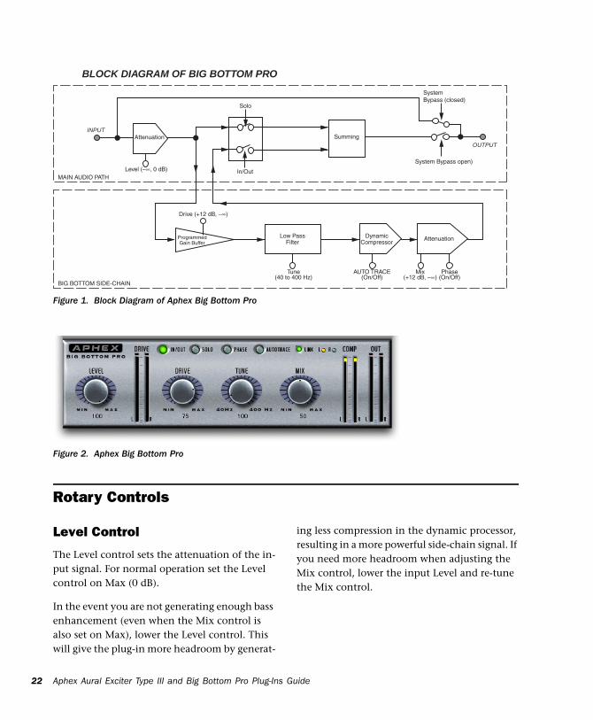
Big Bottom Pro is a single-ended process which can be inserted at any point within the audio chain (see Figure 1 on page 22). The input signal is split into two parts. One part goes to the out-put unmodified, while the other part, known as a side-chain, goes through Big Bottom Pro. The side-chain consists of a tunable low pass filter followed by a dynamic processor.
Big Bottom Pro is patented in the United States, Japan and most of Europe. Big Bottom Pro is a unique bass enhancement that cannot be achieved by any other technique.
Chapter 5: Big Bottom Pro Controls 19
20
Adjusting Plug-In ParametersYou can adjust plug-in controls by dragging the control’s slider or knob, or by typing a value into the control’s text box. Additionally, some plug-ins have switches that can be enabled by click-ing on them.
To adjust a plug-in control:
1 Begin audio playback so that you can hear the control changes in real time.
2 Adjust the controls of the plug-in for the effect you want. Refer to “Editing Parameters Using a Mouse” on page 20 and “Editing Parameters Us-ing a Computer Keyboard” on page 20.
Closing the plug-in will save the most recent changes.
Editing Parameters Using a Mouse
You can adjust rotary controls by dragging hori-zontally or vertically. Parameter values increase as you drag upward or to the right, and decrease as you drag downward or to the left.
Keyboard Shortcuts
For finer adjustments, Control-drag (Win-dows) or Command-drag (Mac) the control.
To return a control to its default value, Alt-click (Windows) or Option-click (Mac) the con-trol.
Aphex Aural Exciter Type III and Big Bottom Pro Plug-Ins
Editing Parameters Using a Computer Keyboard
Some controls have text boxes that display the current value of the parameter. You can edit the numeric value of a parameter with your com-puter keyboard.
If multiple Plug-In windows are open, Tab and keyboard entry remain focused on the plug-in that is the target window.
To change control values with a computer keyboard:
1 Click the text box corresponding to the con-trol that you want to adjust.
2 Change the value.
• To increase a value, press the Up Arrow on your keyboard. To decrease a value, press the Down Arrow on your keyboard.
– or –
• Type the desired value.
3 Do one of the following:
• Press Enter on the numeric keyboard to in-put the value and remain in keyboard edit-ing mode.
– or –
• Press Enter on the alpha keyboard (Win-dows) or Return (Mac) to enter the value and leave keyboard editing mode.
In fields that support values in kilohertz, typing “k” after a number value will multi-ply the value by 1,000. For example, type “8k” to enter a value of 8,000.
To move forward through the different con-trol fields, press the Tab key. To move back-ward, press Shift+Tab.
Guide
Editing Parameters Using a Scroll Wheel
Some controls have text boxes that display the current value of the parameter. You can edit the numeric value of a parameter using a scroll wheel.
To change control values using a scroll wheel:
1 Click the text box corresponding to the con-trol that you want to adjust.
2 To increase a value, scroll up with the scroll wheel. To decrease a value, scroll down with the scroll wheel.
Toggling Switches
To toggle a switch:
Click the switch.
Meters
Drive Meter
The input Drive peak meter indicates the actual peak level to the Big Bottom Pro side-chain.
A red LED at the top of the meter indicates if there is clipping.
Compression Meter
The Compression (Comp) meter indicates the actual amount of compression taking place in the Big Bottom Pro side-chain. If the Comp me-ter is not showing any activity the input level is too low. Adjust the Level and Drive controls ac-cordingly.
Out Meter
The Output peak meter indicates the actual peak level after mixing the Big Bottom Pro side-chain with the original input signal.
A red light at the top of the Out meter indicates if there is clipping.
The Plug-In window header includes a Clip LED that lights red to indicate plug-in clipping. The Plug-In Clip LED follows Pro Tools settings for clip indication. (For more information, see the Pro Tools Reference Guide.
Audition the loudest or peak sections of your audio material to avoid Big Bottom Pro out-put clipping: Use the Out Meter to check for clipping.
Chapter 5: Big Bottom Pro Controls 21
22
Aphex Aural Exciter Type III and Big Bottom Pro Plug-InsFigure 1. Block Diagram of Aphex Big Bottom Pro
BLOCK DIAGRAM OF BIG BOTTOM PRO
INPUTAttenuation
Mix�(+12 dB, –∞)
Tune�(40 to 400 Hz)
AUTO TRACE�(On/Off)
Phase�(On/Off)
Programmed�Gain Buffer
Solo
In/OutLevel (–∞, 0 dB)
Drive (+12 dB, –∞)
MAIN AUDIO PATH
BIG BOTTOM SIDE-CHAIN
Summing
System�Bypass (closed)
System Bypass open)
AttenuationDynamic�Compressor
OUTPUT
Low Pass�Filter
Rotary Controls
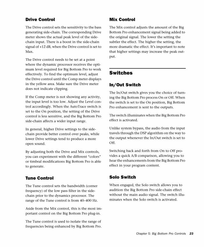
Figure 2. Aphex Big Bottom Pro
Level Control
The Level control sets the attenuation of the in-put signal. For normal operation set the Level control on Max (0 dB).
In the event you are not generating enough bass enhancement (even when the Mix control is also set on Max), lower the Level control. This will give the plug-in more headroom by generat-
ing less compression in the dynamic processor, resulting in a more powerful side-chain signal. If you need more headroom when adjusting the Mix control, lower the input Level and re-tune the Mix control.
Guide
Drive Control
The Drive control sets the sensitivity to the bass generating side-chain. The corresponding Drive meter shows the actual peak level of the side-chain input. There is a boost in the side-chain signal of +12 dB, when the Drive control is set to Max.
The Drive control needs to be set at a point where the dynamic processor receives the opti-mum level required for Big Bottom Pro to work effectively. To find the optimum level, adjust the Drive control until the Comp meter displays in the yellow area. Make sure the Drive meter does not indicate clipping.
If the Comp meter is not showing any activity, the input level is too low. Adjust the Level con-trol accordingly. When the AutoTrace switch is set to the On position, the setting of the Drive control is less sensitive, and the Big Bottom Pro side-chain affects a wider input range.
In general, higher Drive settings to the side-chain provide better control over peaks, while lower Drive settings tend to produce a more open sound.
By adjusting both the Drive and Mix controls, you can experiment with the different “colors” or timbral modifications Big Bottom Pro is able to generate.
Tune Control
The Tune control sets the bandwidth (corner frequency) of the low pass filter in the side-chain prior to the dynamics processor. The range of the Tune control is from 40–400 Hz.
Aside from the Mix control, this is the most im-portant control on the Big Bottom Pro plug-in.
The Tune control is used to isolate the range of frequencies being enhanced by Big Bottom Pro.
Mix Control
The Mix control adjusts the amount of the Big Bottom Pro enhancement signal being added to the original signal. The lower the setting the subtler the effect. The higher the setting, the more dramatic the effect. It’s important to note that higher settings may increase the peak out-put.
Switches
In/Out Switch
The In/Out switch gives you the choice of turn-ing the Big Bottom Pro process On or Off. When the switch is set to the On position, Big Bottom Pro enhancement is sent to the outputs.
The switch illuminates when the Big Bottom Pro effect is activated.
Unlike system bypass, the audio from the input travels through the DSP algorithm on the way to the output whenever the In/Out switch is set to Off.
Switching back and forth from On to Off pro-vides a quick A/B comparison, allowing you to hear the enhancements from the Big Bottom Pro effect in your program content.
Solo Switch
When engaged, the Solo switch allows you to audition the Big Bottom Pro side-chain effect without the main audio signal. The switch illu-minates when the Solo switch is activated.
Chapter 5: Big Bottom Pro Controls 23
24
Phase Switch
The Phase switch allows you to alter the phase of the side-chain signal, which contains the Big Bottom Pro effect, before it is mixed with the original input signal. This function is used as a optional way to change the “quality” of the Big Bottom Pro effect.
The switch illuminates when the Phase switch is activated.
Altering the side-chain signal’s phase dramati-cally effects the sound of the Big Bottom Pro en-hancement. With the Phase switch turned Off, you will recognize the Big Bottom Pro effect found in the Aphex Model 104.
As an exclusive feature for this TDM plug-in, we have added the Phase switch. When activated, the Phase switch alters the Big Bottom Pro effect by setting the side-chain in-phase with the main signal. This increases the output peak level. Use the Mix or Level controls to restore the output peak level if the Drive meter indicates clipping.
AutoTrace Switch
Activating the AutoTrace switch enables an au-tomatic threshold function for the compressor within the Big Bottom Pro side-chain. The Auto-Trace function enables the dynamic processor to self-optimize during normal operation. The switch illuminates when the AutoTrace switch is activated.
This control is particularly useful when you want a subtle Big Bottom Pro effect, or when the peak level of the input material varies over time. The AutoTrace feature is also ideal for changing the sound characteristics of the Big Bottom Pro effect. Drive control adjustments will be reduced when the AutoTrace switch is activated.
Aphex Aural Exciter Type III and Big Bottom Pro Plug-Ins
Link Switch
The Link switch is for stereo operation only. It links the left and right controls so they work as one. Grab a control on one page with the cursor and move it to the desired position. The control on the other page automatically updates. In this way both controls can be set to the exact same position. Stereo controls may be linked tempo-rarily by holding down the Shift key while ad-justing the control.
The switch illuminates when Link is activated.
LR (Left/Right) Switches
The LR switch is for stereo operation only. It al-lows you to view or change parameters on one channel at a time.
The switch for the currently displayed channel illuminates. Clicking the unlit switch changes the display to the other channel.
To edit both channels simultaneously, click on the Link switch.
Guide
chapter 6
Using Big Bottom Pro
By putting Big Bottom Pro to use in a Pro Tools session you will find many creative uses for its powerful processing capabilities.
The remaining sections provide instructions on how to get the most out of Big Bottom Pro.
Inserting Big Bottom Pro on a TrackTo use Big Bottom Pro in a Pro Tools session, in-sert it on a track. Before doing so, make sure the Inserts View is shown in the Mix window.
To show inserts in the Mix window:
Choose View > Mix Window > Inserts.
To insert Big Bottom Pro on a track:
Click the Insert selector on the track and se-lect the plug-in that you want to use.
To remove Big Bottom Pro from a track:
Click the Insert selector and choose No Insert.
Although Big Bottom is typically used as an insert on a track (in the same manner com-pressors and equalizers are used), it can also be used on busses and sends. Refer to the Pro Tools Reference Guide.
Setting the Gain StructureIf the desired amount of Big Bottom Pro effect is limited by a lack of headroom in the input ma-terial, use the Level control to adjust the signal level to avoid clipping. When using Big Bottom Pro with the Phase switch in the Off position, it is possible to achieve a substantial increase in bass energy without significantly increasing the peak level output.
For optimal performance keep the peak hold meter of the Drive meter inside the yellow area.
Optimizing Big Bottom Pro EffectsWhen using Big Bottom Pro, the output signal level is equal to the input signal levels plus the bass enhanced Big Bottom Pro effect. The dy-namic characteristics of Big Bottom Pro are based on a complex algorithm that includes the signal peak level, the average steady staid level as well as the dynamic characteristics. Unlike a bass EQ, which adds a constant boost in the low end, Big Bottom Pro enhancement is added into the input signal dynamically.
Chapter 6: Using Big Bottom Pro 25
26
Starting with the factory settings, experiment with the controls on Big Bottom Pro to hear how this plug-in effects the low-end frequencies of your source material, as follows:
• If the Drive meter is clipping (in the yellow area), adjust the Drive control for optimal op-eration.
• Activate the Solo switch to listen to only the Big Bottom Pro side-chain effect.
• Vary the Tune control to hear the low-pass fil-ter isolate the low-end bandwidths of the orig-inal input signal.
• De-activate the Solo switch and continue to vary the Tune control until you find the opti-mal setting.
• Adjust the Mix control to set the amount of Big Bottom Pro effect.
• Use the In/Out switch for an A/B comparison with the output signal and the original input signal.
• Activate the Phase switch and observe the change in the sound characteristics of the Big Bottom Pro effect. For most applications, leave the Phase switch in the Off position.
• Activate the AutoTrace switch and observe the change in the sound characteristics. Also no-tice that the compression level in the dynamic processor, shown by the Comp meter, is af-fected as well.
• Readjust the Mix control as desired, to experi-ence the benefits of the Big Bottom Pro TDM plug-in. Remember that a little Big Bottom Pro effect goes a long way.
Aphex Aural Exciter Type III and Big Bottom Pro Plug-Ins
Guide
appendix a
DSP Requirements
The number of TDM plug-ins you can use at one time depends on how much DSP power is avail-able in your system. Since the TDM hardware on Pro Tools cards provide dedicated DSP for plug-ins, plug-in performance isn’t limited by CPU processing power.
The DSP tables in this appendix show the theo-retical number of instances of each plug-in that can be powered by a single DSP chip on Pro Tools|HD cards. DSP usage differs according to card type.
There are a total of nine DSP chips on a Pro Tools|HD card (HD Core, HD Process, and HD Accel). HD Core and HD Process cards pro-vide identical chip sets. HD Accel cards provide newer, more powerful DSP chips (making the HD Accel card ideal for DSP-intensive plug-ins, and for high sample rate sessions).
DSP tables show the theoretical maximum performance when no other plug-ins or sys-tem tasks (such as I/O) are sharing avail-able DSP resources. You will typically use more than one type of plug-in simultane-ously. The data in these tables are provided as guidelines to help you gauge the relative efficiency of different plug-ins on your sys-tem. They are not guaranteed performance counts that you should expect to see in typ-ical real-world sessions and usage.
Not all plug-ins are supported on all types of chips. The following tables indicate the number of compatible chips per card.
Using Multi-Mono Plug-Ins on Greater-Than-Stereo Tracks
Plug-Ins used in multi-mono format on greater-than-stereo tracks require one mono instance per channel of the multi-channel audio format. For example, a multi-mono plug-in used on a 5.1 format track, requires six mono instances since there are six audio channels in the 5.1 for-mat.
Monitoring DSP Usage
The System Usage window (Window > System Usage) shows how much DSP is available in your system and how it is being used in the current Pro Tools session.
On 176.4 kHz or 192 kHz stereo tracks, Au-ral Exciter is only available as a multi-mono plug-in.
For more information about DSP usage and allocation, see the Pro Tools Reference Guide.
Appendix A: DSP Requirements 27
28
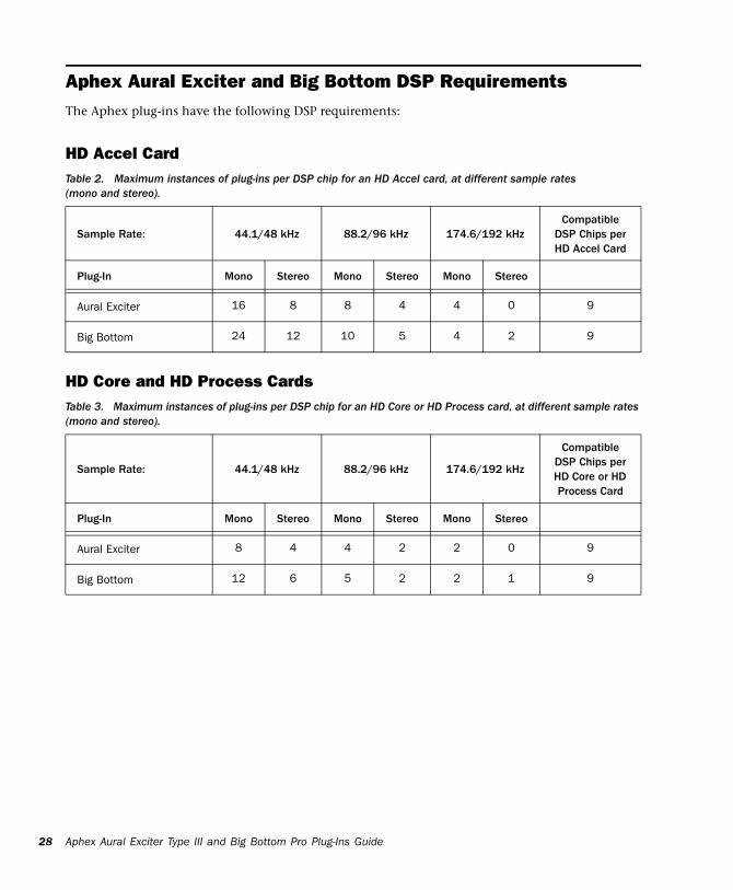
Aphex Aural Exciter and Big Bottom DSP RequirementsThe Aphex plug-ins have the following DSP requirements:
HD Accel Card
Table 2. Maximum instances of plug-ins per DSP chip forAphex Aural Exciter Type III and Big Bottom Pro Plug-Ins
an HD Accel card, at different sample rates
HD Core and HD Process Cards
(mono and stereo).
Sample Rate: 44.1/48 kHz 88.2/96 kHz 174.6/192 kHzCompatible
DSP Chips per HD Accel Card
Plug-In Mono Stereo Mono Stereo Mono Stereo
Aural Exciter 16 8 8 4 4 0 9
Big Bottom 24 12 10 5 4 2 9
Table 3. Maximum instances of plug-ins per DSP chip for
an HD Core or HD Process card, at different sample rates (mono and stereo).Sample Rate: 44.1/48 kHz 88.2/96 kHz 174.6/192 kHz
Compatible DSP Chips per HD Core or HD Process Card
Plug-In Mono Stereo Mono Stereo Mono Stereo
Aural Exciter 8 4 4 2 2 0 9
Big Bottom 12 6 5 2 2 1 9
Guide
appendix b
DSP Delays Incurred by TDM Plug-Ins
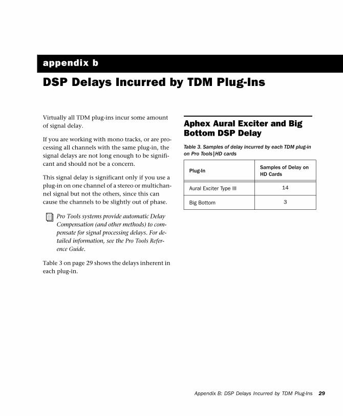
Virtually all TDM plug-ins incur some amount of signal delay.
If you are working with mono tracks, or are pro-cessing all channels with the same plug-in, the signal delays are not long enough to be signifi-cant and should not be a concern.
This signal delay is significant only if you use a plug-in on one channel of a stereo or multichan-nel signal but not the others, since this can cause the channels to be slightly out of phase.
Table 3 on page 29 shows the delays inherent in each plug-in.
Pro Tools systems provide automatic Delay Compensation (and other methods) to com-pensate for signal processing delays. For de-tailed information, see the Pro Tools Refer-ence Guide.
Aphex Aural Exciter and Big Bottom DSP Delay
Table 3. Samples of delay incurred by each TDM plug-in on Pro Tools|HD cards
Plug-InSamples of Delay on HD Cards
Aural Exciter Type III 14
Big Bottom 3
Appendix B: DSP Delays Incurred by TDM Plug-Ins 29

30
Aphex Aural Exciter Type III and Big Bottom Pro Plug-Ins Guide
Aadjusting plug-in parameters
computer keyboard 8, 20keyboard shortcuts 8, 20mouse 8, 20scroll wheel 9, 21toggling switches 9, 21
authorizing software 6AutoTrace switch 24Ax switch 13
Bblock diagram 10, 22boxed version 1Bypass switch 14
Cclipping 16Compression meter 21computer keyboard
adjusting plug-in parameters 8, 20
Ddelay
DSP-induced delays 29Density switch 13Drive control 23Drive meter 9, 21Drive switch 13DSP delays inherent in plug-ins 29DSP requirements 27
Ggain structure 15, 25guide conventions 2
HHarmonics control 12
IIn/Out switch 23inserting Aural Exciter 15inserting Big Bottom Pro 25inserting plug-ins on a track 27installing software 5
Kkeyboard shortcuts
adjusting plug-in parameters 8, 20
LLevel control 10, 22Link switch 14, 24LR (Left/Right) switches 14
Mmeters 9, 21Mix control 12, 23mouse
adjusting plug-in parameters 8, 20
NNull Fill control 11
Ooptimizing Aural Exciter 16optimizing Big Bottom pro 25Out meter 9, 21
index
Index 31
32
Ppackage contents 1Peaking control 11Phase switch 24plug-ins
adjusting parameters 8, 20registration 2
Rregistration 2removing Aural Exciter 15removing Big Bottom Pro 25removing software 6rotary controls 10, 22
Sscroll wheel
adjusting plug-in parameters 9, 21software
authorizing 6installing 5removing 6
Solo switch 13, 23SPR switch 14, 17switches 13, 23
adjusting plug-in parameters 9, 21System Usage window 27
TTDM plug-ins
DSP requirements 27Timbre control 12Tune control 11, 23Tune fader 17
Uusing Aural Exciter 15
Wwebsite 3
Aphex Aural Exciter Type III and Big Bottom Pro Plug-Ins
Guide
Avid2001 Junipero Serra Boulevard Daly City, CA 94014-3886 USA
Technical Support (USA)Visit the Online Support Center at www.avid.com/support
Product InformationFor company and product information, visit us on the web at www.avid.com