Embed Size (px)
Citation preview

Armadillo-800 EVAProduct Manual
A8000-D00Z
Version 1.1.02012/02/28
Atmark Techno, Inc.
Armadillo Site

Armadillo-800 EVA Product Manual
Atmark Techno, Inc.
060-0035 AFT Bldg., N5E2, Chuo-ku, SapporoTEL 011-207-6550 FAX 011-207-6570
Copyright © 2012 Atmark Techno, Inc.
Version 1.1.02012/02/28

Table of Contents1. Preface ............................................................................................................................................... 11
1.1. This Document and Related Files .................................................................................................. 111.2. Document Structure .................................................................................................................... 111.3. Typographical Conventions .......................................................................................................... 11
1.3.1. Fonts ............................................................................................................................. 111.3.2. Command Entry Examples ................................................................................................ 121.3.3. Icons ............................................................................................................................. 12
1.4. Acknowledgements .................................................................................................................... 122. Precautions .......................................................................................................................................... 13
2.1. Product Opening Precautions ........................................................................................................ 132.2. Evaluation Board Precautions ....................................................................................................... 132.3. Safety Precautions ...................................................................................................................... 132.4. Usage Precautions for Products with Wireless LAN Functionality ....................................................... 142.5. Warranty .................................................................................................................................. 152.6. Exporting .................................................................................................................................. 152.7. Trademarks ............................................................................................................................... 15
3. Overview ............................................................................................................................................ 163.1. Board Overview ......................................................................................................................... 163.2. Block Diagram .......................................................................................................................... 18
4. Interface Layout ................................................................................................................................... 204.1. Armadillo-800 EVA Interface Layout ............................................................................................ 204.2. DIP Switch ............................................................................................................................... 21
5. Before Power-on .................................................................................................................................. 235.1. Preparation ............................................................................................................................... 235.2. Connections .............................................................................................................................. 235.3. DIP Switch Configuration ............................................................................................................ 255.4. Serial Communication Software Configuration ................................................................................ 255.5. Installed Software ...................................................................................................................... 25
6. Booting Android ................................................................................................................................... 276.1. Preparation ............................................................................................................................... 276.2. Booting .................................................................................................................................... 286.3. Shutdown ................................................................................................................................. 286.4. Basic Operations ........................................................................................................................ 29
6.4.1. Lock Screen .................................................................................................................... 306.4.2. Home Screen .................................................................................................................. 306.4.3. Application List ............................................................................................................... 31
7. Booting Debian GNU/Linux ................................................................................................................... 337.1. Preparation ............................................................................................................................... 337.2. Booting .................................................................................................................................... 347.3. Login ....................................................................................................................................... 357.4. Shutdown ................................................................................................................................. 35
8. Function Use with Debian GNU/Linux ..................................................................................................... 368.1. Wired LAN ............................................................................................................................... 368.2. Wireless LAN ........................................................................................................................... 37
8.2.1. Preparation ..................................................................................................................... 378.2.2. Wireless Configuration ..................................................................................................... 38
8.3. Time Configuration .................................................................................................................... 458.4. Package Management ................................................................................................................. 468.5. GStreamer ................................................................................................................................ 48
8.5.1. Installing GStreamer ........................................................................................................ 488.5.2. Using GStreamer ............................................................................................................. 48
8.6. X Server ................................................................................................................................... 498.6.1. Installing X Server ........................................................................................................... 49
Armadillo-800 EVA Product Manual Product Manual
3
8.6.2. Starting X Server ............................................................................................................. 498.7. Video ....................................................................................................................................... 50
8.7.1. Displaying Images ........................................................................................................... 508.7.2. Display Video Mode Configuration ..................................................................................... 51
8.8. Camera .................................................................................................................................... 528.9. Audio ....................................................................................................................................... 528.10. Storage ................................................................................................................................... 54
8.10.1. Using Storage ................................................................................................................ 558.10.2. Changing and Formatting Storage Partitions ........................................................................ 55
8.11. LED Backlight ......................................................................................................................... 578.12. LED ....................................................................................................................................... 58
8.12.1. Turning LEDs Off and On ............................................................................................... 588.12.2. Using LED Triggers ....................................................................................................... 58
8.13. User Switch ............................................................................................................................. 598.14. Touchscreen ............................................................................................................................ 60
9. Utilizing SD Booting ............................................................................................................................. 629.1. Boot Disk Creation ..................................................................................................................... 62
9.1.1. Obtaining Files Required for Boot Disk Creation ................................................................... 629.1.2. Partition Creation ............................................................................................................. 639.1.3. File System Creation ........................................................................................................ 649.1.4. System Image Extraction ................................................................................................... 659.1.5. Editing Configuration Files ................................................................................................ 66
9.2. Booting from Boot Disk .............................................................................................................. 6610. Recovery Procedure ............................................................................................................................. 68
10.1. Partition Structure ..................................................................................................................... 6810.2. Total eMMC Recovery .............................................................................................................. 69
10.2.1. Recovery Disk Creation .................................................................................................. 6910.2.2. Recovery Execution ........................................................................................................ 72
10.3. Recovery of a Particular eMMC Root File System .......................................................................... 7310.3.1. Debian GNU/Linux Recovery .......................................................................................... 7310.3.2. Android Recovery .......................................................................................................... 74
10.4. eMMC Bootloader Recovery ...................................................................................................... 7610.4.1. Obtaining Files Required for Bootloader Recovery ............................................................... 7610.4.2. Bootloader Recovery Execution ........................................................................................ 76
11. Development Environment Setup ........................................................................................................... 7711.1. Using ATDE ........................................................................................................................... 77
11.1.1. Obtaining ATDE ............................................................................................................ 7711.1.2. Starting ATDE .............................................................................................................. 78
11.2. Installing Cross Development Tools ............................................................................................. 7811.2.1. Obtaining Cross Development Tool Debian Packages ........................................................... 7811.2.2. Installing Cross Development Tool Debian Packages ............................................................ 78
12. Building the Kernel ............................................................................................................................. 8012.1. Obtaining Source Archive .......................................................................................................... 8012.2. Extracting Source Archive .......................................................................................................... 8012.3. Building ................................................................................................................................. 8012.4. Installing ................................................................................................................................. 80
13. Building the SGX Kernel Modules ......................................................................................................... 8213.1. Obtaining Source Archive .......................................................................................................... 8213.2. Preparing Kernel ...................................................................................................................... 8213.3. Building ................................................................................................................................. 8213.4. Installing ................................................................................................................................. 83
14. Building the Wireless LAN (AWL13) Linux Device Driver ........................................................................ 8514.1. Obtaining Source Archive .......................................................................................................... 8514.2. Preparing Kernel ...................................................................................................................... 8514.3. Building ................................................................................................................................. 85
Armadillo-800 EVA Product Manual Product Manual
4
14.4. Installing ................................................................................................................................. 8615. Building the Bootloader ....................................................................................................................... 88
15.1. Obtaining Source Archive .......................................................................................................... 8815.2. Extracting Source Archive .......................................................................................................... 8815.3. Building ................................................................................................................................. 8815.4. Installing ................................................................................................................................. 89
16. Using JTAG ICE ................................................................................................................................. 9016.1. Preparation .............................................................................................................................. 90
16.1.1. JTAG Cable Connections ................................................................................................ 9016.1.2. DIP Switch Configuration ................................................................................................ 90
16.2. Connection Confirmation ........................................................................................................... 9016.3. Debugger Support ..................................................................................................................... 90
17. Linux Kernel Specifications .................................................................................................................. 9117.1. Default Configuration ................................................................................................................ 9117.2. Android Functionality ............................................................................................................... 9117.3. Linux Driver List ...................................................................................................................... 91
18. Interface Specifications ........................................................................................................................ 9418.1. CON1 (Camera Module Interface) ............................................................................................... 9418.2. CON2 (Expansion Bus Interface) ................................................................................................. 9418.3. CON3 (Digital HD Output Interface) ............................................................................................ 9618.4. CON4 (Composite Video Output Interface) ................................................................................... 9618.5. CON5 (H-UDI JTAG Interface) .................................................................................................. 9618.6. CON6 (ARM JTAG Interface) .................................................................................................... 9718.7. CON7 (SD Interface 1) .............................................................................................................. 9818.8. CON8 (SD Interface 2) .............................................................................................................. 9818.9. CON9 (RTC External Backup Interface) ....................................................................................... 9918.10. CON10 - CON13 (Audio Interfaces) ........................................................................................... 99
18.10.1. CON10 (Mono Mic In Interface) ..................................................................................... 9918.10.2. CON11 (Stereo Headphone Out Interface) ......................................................................... 9918.10.3. CON12 (Stereo Line Out (L) Interface) ............................................................................. 9918.10.4. CON13 (Stereo Line Out (R) Interface) .......................................................................... 100
18.11. CON14 (AWL13 Module Interface) ......................................................................................... 10018.12. CON15 (Expansion Interface) ................................................................................................. 10118.13. CON16 (LCD Interface 1) ...................................................................................................... 10218.14. CON17 (LCD Interface 2) ...................................................................................................... 10318.15. CON19 (Power In Interface) ................................................................................................... 10518.16. CON20 (USB Interface 1) ...................................................................................................... 10518.17. CON21 (USB Interface 2) ...................................................................................................... 10518.18. CON22 (Serial Interface) ........................................................................................................ 10618.19. CON23 (LAN Interface) ......................................................................................................... 10618.20. CON24 (USB Interface 3) ...................................................................................................... 10618.21. LED1 (Camera LED) ............................................................................................................. 10718.22. LED2 (Power LED) .............................................................................................................. 10718.23. LED3 - LED6 (User LEDs) .................................................................................................... 10718.24. LED7, LED8 (LAN LEDs) ..................................................................................................... 10718.25. SW1 (Function Selection Switch) ............................................................................................. 10818.26. SW2 (Reset Switch) .............................................................................................................. 10818.27. SW3 - SW6 (User Switches) ................................................................................................... 108
19. Board Outline Diagrams ..................................................................................................................... 110A. Hermit-At Bootloader ......................................................................................................................... 112
A.1. version .................................................................................................................................. 112A.1.1. version Example ........................................................................................................... 113
A.2. info ....................................................................................................................................... 113A.2.1. info Example ................................................................................................................ 113
A.3. mac ....................................................................................................................................... 113
Armadillo-800 EVA Product Manual Product Manual
5

A.3.1. mac Example ............................................................................................................... 114A.4. setenv and clearenv .................................................................................................................. 114
A.4.1. setenv/clearenv Example ................................................................................................ 114A.4.2. Linux Kernel Parameters ................................................................................................ 114
A.5. setbootdevice .......................................................................................................................... 114A.5.1. setbootdevice Example ................................................................................................... 115
A.6. frob ....................................................................................................................................... 115A.7. boot ...................................................................................................................................... 115
A.7.1. boot Example ............................................................................................................... 116
Armadillo-800 EVA Product Manual Product Manual
6
List of Figures3.1. Armadillo-800 EVA Block Diagram ...................................................................................................... 194.1. Armadillo-800 EVA Interface Layout Diagram ........................................................................................ 204.2. DIP Switch (SW1) Configuration (Factory Default) .................................................................................. 225.1. Armadillo-800 EVA Connections Example ............................................................................................. 245.2. DIP Switch Configuration .................................................................................................................... 256.1. DIP Switch Boot Mode Configuration .................................................................................................... 276.2. Operating System Boot Configuration Change Procedure (Android) ............................................................ 276.3. Boot Log (Android) ............................................................................................................................ 286.4. Phone Options Screen: Power off .......................................................................................................... 296.5. Power Off Screen: OK Button .............................................................................................................. 296.6. Power Off Progress Screen: Shutting Down Spinner ................................................................................. 296.7. Lock Screen ...................................................................................................................................... 306.8. Home Screen ..................................................................................................................................... 316.9. Home Screen: Application List Button ................................................................................................... 316.10. Application List Screen ...................................................................................................................... 317.1. DIP Switch Boot Mode Configuration .................................................................................................... 337.2. Boot Configuration Change Procedure (Debian) ....................................................................................... 337.3. Boot Log (Linux) ............................................................................................................................... 347.4. Shutdown ......................................................................................................................................... 358.1. Enabling Wired LAN with the ifup Command ......................................................................................... 368.2. Deactivating Wired LAN with the ifdown Command ................................................................................ 378.3. Infrastructure Mode: WPA2-PSK (AES) Configuration Procedure ............................................................... 428.4. Infrastructure Mode: WPA2-PSK (AES) Configuration Confirmation Procedure ............................................ 438.5. Infrastructure Mode: WEP Configuration Procedure ................................................................................. 438.6. Infrastructure Mode: WEP Configuration Confirmation Procedure ............................................................... 448.7. Ad-Hoc Mode: WEP Configuration Procedure ......................................................................................... 458.8. Ad-Hoc Mode: WEP Configuration Confirmation Procedure ...................................................................... 458.9. System Clock Configuration ................................................................................................................. 468.10. Hardware Clock Configuration ............................................................................................................ 468.11. Installing GStreamer ......................................................................................................................... 488.12. Playing Test Audio ........................................................................................................................... 498.13. Playing Test Audio on Armadillo-800 EVA ........................................................................................... 498.14. Installing X Server ............................................................................................................................ 498.15. Starting X Server (LCD) .................................................................................................................... 508.16. Starting X Server (Display) ................................................................................................................ 508.17. X Server Boot Screen ........................................................................................................................ 508.18. JPEG Image Display (LCD) ............................................................................................................... 518.19. JPEG Image Display (Display) ............................................................................................................ 518.20. Using Image Files in gnome-backgrounds Package ................................................................................. 518.21. Displaying Configurable Video Modes (Display) .................................................................................... 518.22. Video Mode Configuration (Display) ................................................................................................... 528.23. Displaying Video from Camera on LCD ............................................................................................... 528.24. Audio Recording .............................................................................................................................. 538.25. Audio File Playback (hw:0) ................................................................................................................ 538.26. Audio File Playback (hw:1) ................................................................................................................ 538.27. Outputting Mic Input to hw:0 .............................................................................................................. 548.28. Using Audio Files in gnome-audio Package ........................................................................................... 548.29. Mounting Storage ............................................................................................................................. 558.30. Unmounting Storage ......................................................................................................................... 558.31. Altering Storage Partitions ................................................................................................................. 568.32. Formatting Storage ........................................................................................................................... 578.33. Altering LED Backlight Brightness ...................................................................................................... 578.34. Turning LED3 On ............................................................................................................................. 58
Armadillo-800 EVA Product Manual Product Manual
7
8.35. Turning LED3 Off ............................................................................................................................ 588.36. Obtain the Current State of LED3 ........................................................................................................ 588.37. Setting LED3 Trigger to timer ............................................................................................................. 598.38. Displaying LED3 Trigger ................................................................................................................... 598.39. Installing evtest ................................................................................................................................ 608.40. Capturing User Switch Events ............................................................................................................. 608.41. Capturing Touchscreen Events ............................................................................................................ 619.1. Partition Creation Procedure ................................................................................................................. 639.2. Partition Confirmation Procedure .......................................................................................................... 649.3. File System Creation Procedure ............................................................................................................ 659.4. System Image Extraction Procedure ....................................................................................................... 659.5. Editing fstab ...................................................................................................................................... 669.6. Booting from Boot Disk ...................................................................................................................... 6710.1. Partition Creation Procedure ............................................................................................................... 6910.2. Partition Confirmation Procedure ......................................................................................................... 7110.3. File System Creation Procedure ........................................................................................................... 7110.4. File Extraction Procedure ................................................................................................................... 7210.5. Debian GNU/Linux Recovery Procedure ............................................................................................... 7410.6. Android Recovery Procedure .............................................................................................................. 7510.7. Bootloader Recovery Procedure .......................................................................................................... 7611.1. Install Command for 64-bit PC Cross Development Tool Debian Packages .................................................. 7811.2. Install Command for 32-bit PC Cross Development Tool Debian Packages .................................................. 7912.1. Extracting Source Archive .................................................................................................................. 8012.2. Building the Kernel ........................................................................................................................... 8012.3. Installing Kernel Image to Android System ........................................................................................... 8112.4. Installing Kernel Image to Debian GNU/Linux System ............................................................................ 8113.1. Building the SGX Kernel Modules ....................................................................................................... 8313.2. Installing SGX Kernel Modules ........................................................................................................... 8414.1. Building the AWL13 Driver ............................................................................................................... 8614.2. Installing AWL13 Kernel Module ........................................................................................................ 8715.1. Extracting Source Archive .................................................................................................................. 8815.2. Building the Bootloader ..................................................................................................................... 8915.3. Installing Bootloader Image ................................................................................................................ 8916.1. DIP Switch JTAG Configuration (ARM) ............................................................................................... 9018.1. AC Adapter Polarity Mark ................................................................................................................ 10518.2. Reset Block Diagram ...................................................................................................................... 10819.1. Board Outline and Fixing Hole Measurements ..................................................................................... 11019.2. Connector Center Measurements ....................................................................................................... 111A.1. version Syntax ................................................................................................................................ 113A.2. version Example .............................................................................................................................. 113A.3. info Syntax ..................................................................................................................................... 113A.4. info Example .................................................................................................................................. 113A.5. mac Syntax .................................................................................................................................... 113A.6. mac Example .................................................................................................................................. 114A.7. setenv/clearenv Syntax ..................................................................................................................... 114A.8. setenv and clearenv Example ............................................................................................................. 114A.9. setbootdevice Syntax ........................................................................................................................ 115A.10. Assigning Partition 4 of Internal Storage as Boot Device ....................................................................... 115A.11. Assigning SD Card as Boot Device ................................................................................................... 115A.12. boot Syntax .................................................................................................................................. 115A.13. boot Example ................................................................................................................................ 116
Armadillo-800 EVA Product Manual Product Manual
8
List of Tables1.1. Fonts ............................................................................................................................................... 111.2. Relationship Between Prompt and Execution Environment ......................................................................... 121.3. Abbreviations Used in Command Entry Examples .................................................................................... 123.1. Armadillo-800 EVA Specifications ........................................................................................................ 164.1. Armadillo-800 EVA Interfaces ............................................................................................................. 214.2. DIP Switch Configuration (Factory Default) ............................................................................................ 214.3. DIP Switch (SW1) Switch Functions ...................................................................................................... 225.1. DIP Switch Configuration .................................................................................................................... 255.2. Serial Communication Configuration ..................................................................................................... 255.3. Installed Operating Systems ................................................................................................................. 266.1. User Switch Names and Functions ......................................................................................................... 307.1. Serial Console Login Username and Password ......................................................................................... 358.1. Infrastructure Mode: WPA-PSK / WPA2-PSK Parameters Example ............................................................ 428.2. Infrastructure Mode: WEP Parameters Example ....................................................................................... 438.3. Ad-Hoc Mode: WEP Parameters Example .............................................................................................. 448.4. Element Types ................................................................................................................................... 498.5. Interfaces and ALSA Devices ............................................................................................................... 538.6. Equipment to Connect to Audio Interfaces .............................................................................................. 538.7. Storage Devices ................................................................................................................................. 548.8. Files Used for Brightness Configuration ................................................................................................. 578.9. LEDs and Corresponding LED Class Directories ...................................................................................... 588.10. Triggers Configurable with the trigger File ............................................................................................ 598.11. Switches and Corresponding Input Device Files ..................................................................................... 599.1. Boot Disk Structure ............................................................................................................................ 629.2. Files Required for Boot Disk Creation .................................................................................................... 6310.1. Internal Storage Partition Structure ...................................................................................................... 6810.2. eMMC Boot Partitions ....................................................................................................................... 6810.3. Internal Storage Region Use ............................................................................................................... 6810.4. Files Required for Recovery Disk Creation ............................................................................................ 6910.5. Recover Progress and LEDs ............................................................................................................... 7310.6. Candidate Root File Systems for Recovery ............................................................................................ 7310.7. Files Required for Debian GNU/Linux Recovery .................................................................................... 7410.8. Files Required for Android Recovery ................................................................................................... 7510.9. Files Required for Bootloader Recovery ................................................................................................ 7611.1. ATDE4 Types .................................................................................................................................. 7711.2. Usernames and Passwords .................................................................................................................. 7817.1. Operating System and Default Configuration ......................................................................................... 9117.2. Main Configuration for Android Functionality ....................................................................................... 9118.1. CON1 Signals .................................................................................................................................. 9418.2. CON2 Signals .................................................................................................................................. 9418.3. CON3 Signals .................................................................................................................................. 9618.4. CON4 Signals .................................................................................................................................. 9618.5. CON5 Signals .................................................................................................................................. 9718.6. CON6 Signals .................................................................................................................................. 9718.7. CON7 Signals .................................................................................................................................. 9818.8. CON8 Signals .................................................................................................................................. 9818.9. CON9 Signals .................................................................................................................................. 9918.10. CON10 Signals .............................................................................................................................. 9918.11. CON11 Signals .............................................................................................................................. 9918.12. CON12 Signals ............................................................................................................................ 10018.13. CON13 Signals ............................................................................................................................ 10018.14. CON14 Signals ............................................................................................................................ 10018.15. CON15 Signals ............................................................................................................................ 101
Armadillo-800 EVA Product Manual Product Manual
9
18.16. CON16 Signals ............................................................................................................................ 10218.17. CON17 Signals ............................................................................................................................ 10418.18. CON19 Signals ............................................................................................................................ 10518.19. CON20 Signals ............................................................................................................................ 10518.20. CON21 Signals ............................................................................................................................ 10618.21. CON22 Signals ............................................................................................................................ 10618.22. CON23 Signals ............................................................................................................................ 10618.23. CON24 Signals ............................................................................................................................ 10718.24. LED1 Behavior ............................................................................................................................ 10718.25. LED Behavior .............................................................................................................................. 10718.26. LED3 - LED6 Behavior ................................................................................................................. 10718.27. LED7, LED8 Behavior .................................................................................................................. 10718.28. SW1 Signals ................................................................................................................................ 10818.29. SW2 Function .............................................................................................................................. 10818.30. SW3 - SW6 Functions ................................................................................................................... 108A.1. Well Used Linux Kernel Parameters .................................................................................................... 114A.2. frob Command ................................................................................................................................ 115
Armadillo-800 EVA Product Manual Product Manual
10

Chapter 1. Preface
Thank you for purchasing the Armadillo-800 EVA.
1.1. This Document and Related Files
For all manuals including this document and also all other related files such as source files and image files, we recommendusing the newest versions available. Before continuing with this document, please check the Armadillo Site for informationon the latest versions.
Also, the following user only content is available to those who have registered their purchased Armadillo-800 EVA atthe Atmark Techno User Site.
• Purchaser only software
• Armadillo-800 EVA circuit diagrams
In order to carry out product registration, please access the "User Only Content" menu on the user site.
A legitimate authentication file extracted from the purchased product must be uploaded during product registration. Theprocedure to extract the authentication file is linked to from the "Armadillo-800 EVA Product Registration" page.
1.2. Document Structure
This document comprises of Chapters 1 to 19 and an appendix.
Chapters 1 to 4 introduce Armadillo-800 EVA.
Chapters 5 to 10 explain how to use Armadillo-800 EVA. This includes explanations on the installed software and therecovery procedure used to return the software to its factory default state.
Chapters 11 to 17 cover the information required for software development. This includes preparation of the developmentenvironment and how to build the various software.
Chapters 18 to 19 explain the hardware specifications.
Finally, the appendix explains the functionality of the bootloader.
1.3. Typographical Conventions
1.3.1. Fonts
Fonts are used in the following ways in this document.
Table 1.1. Fonts
Font Example Explanation
Plain text font Used for standard text
[PC ~]$ ls Shell prompt and user input text
text Text that is either displayed, is to be edited, or is a comment
Armadillo-800 EVA Product Manual Preface
11
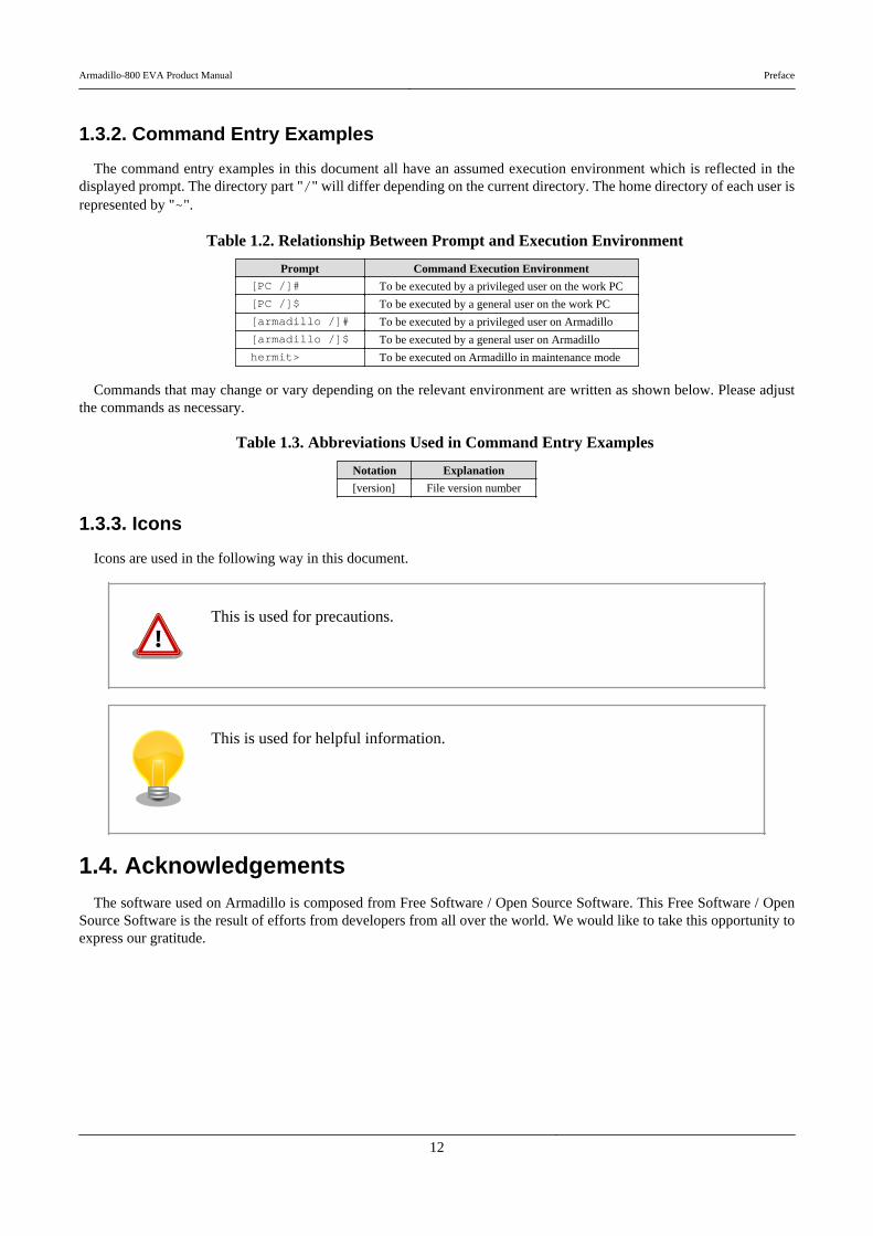
1.3.2. Command Entry Examples
The command entry examples in this document all have an assumed execution environment which is reflected in thedisplayed prompt. The directory part "/" will differ depending on the current directory. The home directory of each user isrepresented by "~".
Table 1.2. Relationship Between Prompt and Execution Environment
Prompt Command Execution Environment[PC /]# To be executed by a privileged user on the work PC
[PC /]$ To be executed by a general user on the work PC
[armadillo /]# To be executed by a privileged user on Armadillo
[armadillo /]$ To be executed by a general user on Armadillo
hermit> To be executed on Armadillo in maintenance mode
Commands that may change or vary depending on the relevant environment are written as shown below. Please adjustthe commands as necessary.
Table 1.3. Abbreviations Used in Command Entry Examples
Notation Explanation
[version] File version number
1.3.3. Icons
Icons are used in the following way in this document.
This is used for precautions.
This is used for helpful information.
1.4. AcknowledgementsThe software used on Armadillo is composed from Free Software / Open Source Software. This Free Software / Open
Source Software is the result of efforts from developers from all over the world. We would like to take this opportunity toexpress our gratitude.
Armadillo-800 EVA Product Manual Preface
12

Chapter 2. Precautions
2.1. Product Opening Precautions
Please check the following items before opening the product.
• In order to use this product, the "Software License Agreement" (included inthe "Please Read First" documentation included with this product) must beagreed to. Please open the product only after having checked and agreed tothe "Software License Agreement".
2.2. Evaluation Board Precautions
Products sold as a "development set" or an "evaluation set" (hereafter, referred to as an "evaluation board") are forevaluation use during technical development or demonstration. Please use the product with an understanding of the followingpoints.
• Evaluation boards are assumed to be handled in accordance with good tech-nical and practical standards by engineers with knowledge and practical ex-perience of electronics.
• Evaluation boards are unfinished products in terms of the design, sale andproduction protective measures normally required of final products used bygeneral consumers.
• Only a one year replacement warranty from time of purchase is provided forevaluation boards as laid out in our product warranty policy.
• Aside from the above replacement warranty, no explicit or implied guarantee,including the guarantee that the evaluation board is fit for a particular purpose,and any other form of guarantee, is offered by us to the purchaser.
• Even if a malfunction occurs in the evaluation board or in the parts it consistsof, we will not analyze the cause of the malfunction.
2.3. Safety Precautions
In order to use this product safely, please take special note of the following precautions.
• Be sure to read all product manuals and related documentation before usingthis product. Please use this product correctly and safely making sure to followall usage precautions.
Armadillo-800 EVA Product Manual Precautions
13
• When operating or extending this product in a way not described in the productmanuals, please do so safely and on your own responsibility after having fullyunderstood the materials on our web site and any other technical information.
• Please do not install this product in a place with a lot of water, moisture, dustor soot. This could cause a fire, product failure or electric shock.
• Some parts of this product generate heat and can reach high temperatures.Depending on the surrounding temperature and on how this product is han-dled, this may cause burns. Please do not touch the electronic components orthe surrounding area while the product is powered on or before it has cooleddown after being powered off.
• When using this product in the development of devices or systems to originalspecifications, please carry out the design and development after having thor-oughly read and fully understood the product manuals and related materials,the technical information offered on our web site and related device datasheets. Also, please carry out full tests beforehand in order to provide andmaintain reliability and safety.
• This product is not intended for uses that require extremely high reliabilityand safety in terms of functionality and accuracy (such as medical equipment,traffic control systems, combustion control systems, safety equipment and soon). If this product is used in these kinds of equipment, devices or systems,this company will not be held responsible in any way for any accident resultingin injury or death, fire or damage and so on.
• This product uses semiconductor components designed for generic electronicsequipment such as office automation equipment, communications equipment,measurement equipment and machine tools. It is possible that a foreign noiseor surge may cause this product to malfunction or fail. To ensure there willbe no risk to life, the body or property in the event of malfunction or failure,be sure to take all possible measures in regard to device safety design, suchas using protection circuits like limit switches or fuse breakers, or systemredundancy, and to only use the device after taking measures to ensure suf-ficient reliability and safety.
• Please do not use products with Wireless LAN functionality in places nearmedical devices such as heart pacemakers and hearing aids, automatic controlequipment such as fire alarms and automatic doors, microwave ovens, ad-vanced electronic equipment or televisions and radios, or near "Premises Ra-dio Stations" for "Mobile Body Identification" or "Specified Low Power Ra-dio Stations". The radio waves emitted by this product may cause these typesof devices to malfunction.
2.4. Usage Precautions for Products with Wireless LAN Func-tionality
This product uses 2.4GHz band radio waves. As it uses radio waves when operating, it may cause electromagneticinterference and radio frequency interference.
Armadillo-800 EVA Product Manual Precautions
14
• Please do not use this product in places near medical devices such as heartpacemakers and hearing aids, automatic control equipment such as fire alarmsand automatic doors, microwave ovens, advanced electronic equipment ortelevisions and radios.
• Please do not use this product near "Premises Radio Stations" for "MobileBody Identification" or "Specified Low Power Radio Stations".
• If radio frequency interference between this product and similar wireless sta-tions or other devices does occur, please promptly change the place of use orstop operating the product (stop using the radio waves).
2.5. WarrantyAs laid out in the "Product Warranty Policy" which is provided with this product or available on our web site, the main
board of this product is covered by a one year replacement warranty from time of purchase. Please note that the other includedgoods and software are not covered by the warranty.
Product Warranty Policy http://www.atmark-techno.com/support/warranty-policy
2.6. ExportingThis product has as a general rule been developed and manufactured with the assumption that it will be used within Japan.
When exporting this product, it is the responsibility of the exporter to follow all export related law and carry out all requiredprocedures. No guarantee is made in regards to whether or not this product conforms to any overseas laws or regulations.This product and related technology may not be used for the purpose of development of weapons of mass destruction, forthe purpose of military use or other military related uses, or in devices which have had their production, use, sale or pro-curement prohibited by national or overseas law or regulations.
2.7. Trademarks• Armadillo is a registered trademark of Atmark Techno, Inc. All other company names, product names and related
trademarks are the property of their respective owners. TM and (c) marks are omitted.
• The SD, SDHC, microSD, microSDHC and SDIO logos are trademarks of SD-3C, LLC.
Armadillo-800 EVA Product Manual Precautions
15

Chapter 3. Overview
3.1. Board Overview
Armadillo-800 EVA is an evaluation board that includes the Renesas Electronics "R-Mobile A1" processor (ARM Cortex-A9, 800MHz max CPU clock), 512MB of DRAM (DDR3-800) and 8GB of flash memory (eMMC). It has numerousmultimedia functions including a 5 inch LCD (WVGA) capacitive touchscreen panel, digital HD output support and a 3.1Mpixel CMOS camera module. It also has the IEEE802.11b/g/n compliant "Armadillo-WLAN (AWL13)" wireless LANmodule for industrial embedded devices included as standard. With a whole assortment of modules that can be difficult toobtain included, it is possible to evaluate a large number of functions.
The main specifications of Armadillo-800 EVA are as shown below.
Table 3.1. Armadillo-800 EVA Specifications
Processor Renesas Electronics R-Mobile A1 (R8A77404DBA)
CPU Core
ARM Cortex-A9 single core
Instruction / data cache: 32kByte / 32kByte
L2 cache: 256kByte
Media processing engine (NEON) included
Floating-point coprocessor (VFPv3) included
System Clocks
CPU core clock: 792MHz (800MHz max[a])
DDR clock: 396MHz (400MHz max[a])
Internal bus clock: 198MHz (200MHz max[a])
Expansion bus clock: 99MHz (100MHz max[a])
Oscillation source clock: 24MHz
RAM DDR3 SDRAM: 512MByte (32bit width) (DDR3-800)
Flash Memory eMMC NAND flash memory: 8GByte
LAN (Ethernet) 10BASE-T/100BASE-TX with AUTO-MDIX support
Wireless LAN SDHI1[b] Armadillo-WLAN module (AWL13)
IEEE 802.11b/g/n support (72.2Mbps max[c])
Serial (UART)
7 channels max
SCIFA0[d] +3.3V CMOS levels with flow control pins (CTS, RTS)
Expansion I/O Connector
SCIFA1RS-232C levels with no flow control pins
D-Sub 9-pin connector
SCIFA2[e] +3.3V CMOS levels with flow control pins (CTS, RTS) and synchronous clock pin (SCK)
Expansion I/O Connector
SCIFA4[f] +3.3V CMOS levels with no flow control pins
Expansion I/O Connector
SCIFA6[d] +3.3V CMOS levels with no flow control pins but with synchronous clock pin (SCK)
Expansion I/O Connector
SCIFA7[g] +3.3V CMOS levels with no flow control pins
LCD Expansion I/F Connector
SCIFB[h] +3.3V CMOS levels with no flow control pins but with synchronous clock pin (SCK)
Expansion I/O Connector or LCD Expansion I/F Connector
USB
2 channels
USB0[i]
USB HOST (High Speed support)
Type A connector
USB DEVICE (High Speed support)
Type B connector
USB1USB HOST (High Speed support)
Type A connector
Armadillo-800 EVA Product Manual Overview
16
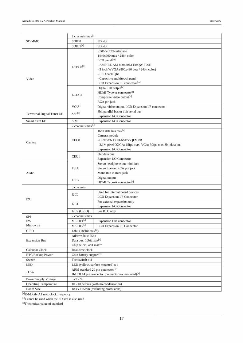
SD/MMC
2 channels max[j]
SDHI0 SD slot
SDHI1[k] SD slot
Video
LCDC0[l]
RGB/YCrCb interface
1440x900 max / 24bit color
LCD panel[m]
- AMPIRE AM-800480L1TMQW-T00H
- 5 inch WVGA (800x480 dots / 24bit color)
- LED backlight
- Capacitive multitouch panel
LCD Expansion I/F connector[m]
LCDC1
Digital HD output[n]
HDMI Type-A connector[o]
Composite video output[n]
RCA pin jack
VOU[l] Digital video output, LCD Expansion I/F connector
Terrestrial Digital Tuner I/F SSP[d] 8bit parallel bus or 1bit serial bus
Expansion I/O Connector
Smart Card I/F SIM Expansion I/O Connector
Camera
2 channels max[p]
CEU0
16bit data bus max[q]
Camera module
- CRESYN DCB-NSB55QFMRB
- 3.1M pixel QXGA: 15fps max, VGA: 30fps max 8bit data bus
Expansion I/O Connector
CEU18bit data bus
Expansion I/O Connector
Audio
FSIA
Stereo headphone out mini-jack
Stereo line out RCA pin jack
Mono mic in mini-jack
FSIBDigital output
HDMI Type-A connector[o]
I2C
3 channels
I2C0Used for internal board devices
LCD Expansion I/F Connector
I2C1For external expansion only
Expansion I/O Connector
I2C2 (GPIO) For RTC only
SPII2SMicrowire
2 channels max
MSIOF1[r] Expansion Bus connector
MSIOF2[s] LCD Expansion I/F Connector
GPIO 13bit (188bit max[t])
Expansion Bus
Address bus: 25bit
Data bus: 16bit max[u]
Chip select: 4bit max[u]
Calendar Clock Real-time clock
RTC Backup Power Coin battery support[v]
Switch Tact switch x 4
LED LED (yellow, surface mounted) x 4
JTAGARM standard 20 pin connector[w]
H-UDI 14 pin connector (connector not mounted)[x]
Power Supply Voltage 5V+-5%
Operating Temperature 10 - 40 celcius (with no condensation)
Board Size 183 x 135mm (excluding protrusions)[a]R-Mobile A1 max clock frequency[b]Cannot be used when the SD slot is also used[c]Theoretical value of standard
Armadillo-800 EVA Product Manual Overview
17

[d]Cannot be used when some specific CEU1 signals are also used[e]Cannot be used when some specific SSP and SIM signals are also used[f]Cannot be used when some specific SSP signals are also used[g]Cannot be used when some specific LCDC0 signals are also used[h]Cannot be used when some specific SSP and LCDC0 signals are also used[i]USB HOST and USB DEVICE cannot be used at the same time[j]The number of channels when SDHI1 is selected for the SD slot[k]Cannot be used when wireless LAN is also used[l]LCDC0 and VOU cannot be used at the same time[m]The LCD panel and LCD Expansion I/F connector cannot be used at the same time[n]Digital HD output and composite video cannot be used at the same time[o]The video and audio HDMI Type-A connectors are the same single connector[p]The number of channels when CEU0 is used with 8bit data bus[q]The maximum number of bits when CEU1 is not used[r]Cannot be used when some specific expansion bus signals are also used[s]Cannot be used when some specific LCDC0 signals are also used[t]Total number of pins usable as GPIO with the pin multiplexing function on the R-Mobile A1[u]Maximum number of bits when eMMC is not used[v]Battery not included[w]The ARM connector and H-UDI connector cannot be used at the same time as they share the same signal lines[x]Connector not mounted
3.2. Block DiagramThe block diagram of Armadillo-800 EVA is as shown below.
Armadillo-800 EVA Product Manual Overview
18
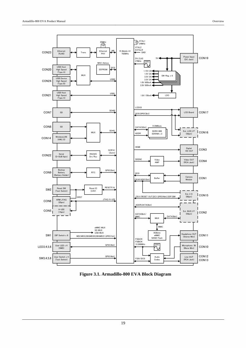
Figure 3.1. Armadillo-800 EVA Block Diagram
Armadillo-800 EVA Product Manual Overview
19

Chapter 4. Interface Layout
The following describes the interface layout of Armadillo-800 EVA. Please check the location of each interface.
4.1. Armadillo-800 EVA Interface Layout
Figure 4.1. Armadillo-800 EVA Interface Layout Diagram
Armadillo-800 EVA Product Manual Interface Layout
20
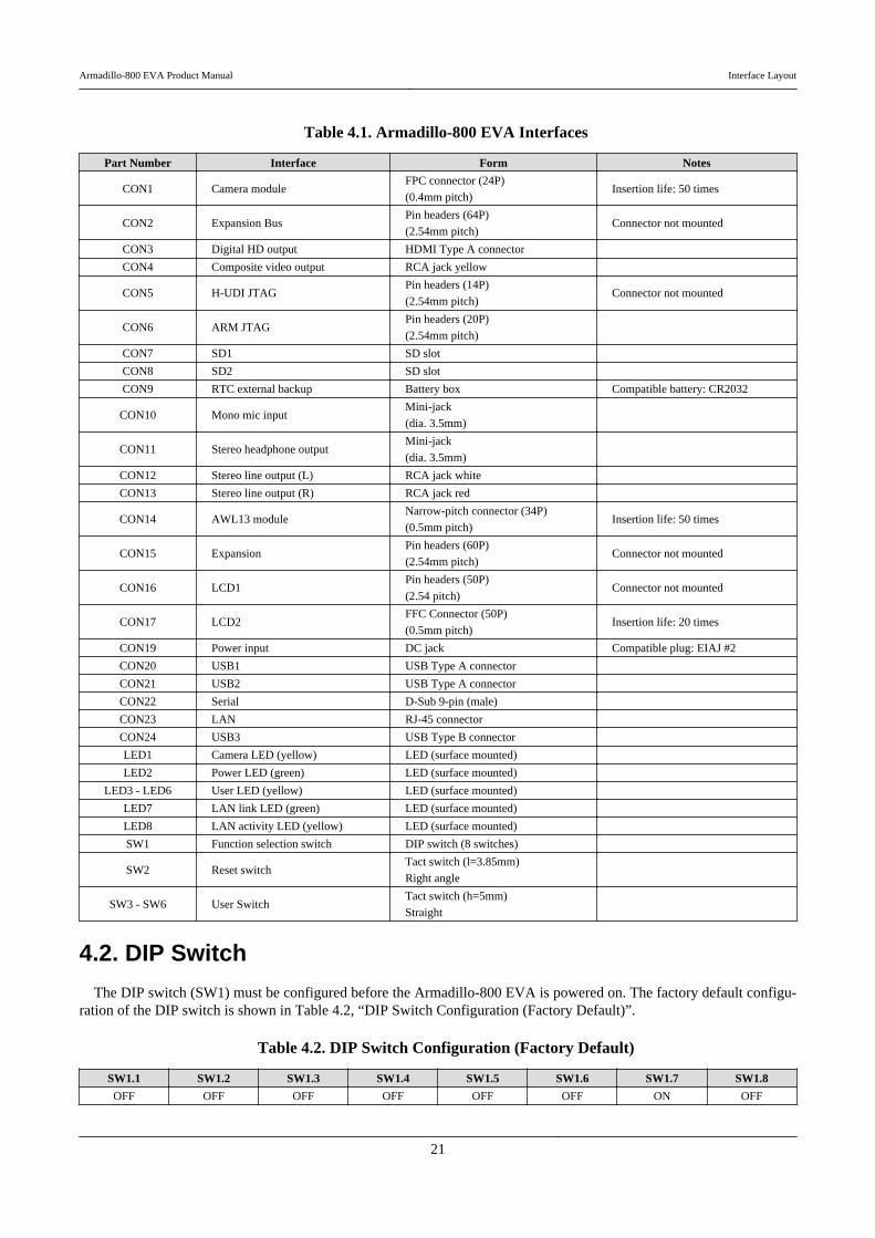
Table 4.1. Armadillo-800 EVA Interfaces
Part Number Interface Form Notes
CON1 Camera moduleFPC connector (24P)
(0.4mm pitch)Insertion life: 50 times
CON2 Expansion BusPin headers (64P)
(2.54mm pitch)Connector not mounted
CON3 Digital HD output HDMI Type A connector
CON4 Composite video output RCA jack yellow
CON5 H-UDI JTAGPin headers (14P)
(2.54mm pitch)Connector not mounted
CON6 ARM JTAGPin headers (20P)
(2.54mm pitch)
CON7 SD1 SD slot
CON8 SD2 SD slot
CON9 RTC external backup Battery box Compatible battery: CR2032
CON10 Mono mic inputMini-jack
(dia. 3.5mm)
CON11 Stereo headphone outputMini-jack
(dia. 3.5mm)
CON12 Stereo line output (L) RCA jack white
CON13 Stereo line output (R) RCA jack red
CON14 AWL13 moduleNarrow-pitch connector (34P)
(0.5mm pitch)Insertion life: 50 times
CON15 ExpansionPin headers (60P)
(2.54mm pitch)Connector not mounted
CON16 LCD1Pin headers (50P)
(2.54 pitch)Connector not mounted
CON17 LCD2FFC Connector (50P)
(0.5mm pitch)Insertion life: 20 times
CON19 Power input DC jack Compatible plug: EIAJ #2
CON20 USB1 USB Type A connector
CON21 USB2 USB Type A connector
CON22 Serial D-Sub 9-pin (male)
CON23 LAN RJ-45 connector
CON24 USB3 USB Type B connector
LED1 Camera LED (yellow) LED (surface mounted)
LED2 Power LED (green) LED (surface mounted)
LED3 - LED6 User LED (yellow) LED (surface mounted)
LED7 LAN link LED (green) LED (surface mounted)
LED8 LAN activity LED (yellow) LED (surface mounted)
SW1 Function selection switch DIP switch (8 switches)
SW2 Reset switchTact switch (l=3.85mm)
Right angle
SW3 - SW6 User SwitchTact switch (h=5mm)
Straight
4.2. DIP Switch
The DIP switch (SW1) must be configured before the Armadillo-800 EVA is powered on. The factory default configu-ration of the DIP switch is shown in Table 4.2, “DIP Switch Configuration (Factory Default)”.
Table 4.2. DIP Switch Configuration (Factory Default)
SW1.1 SW1.2 SW1.3 SW1.4 SW1.5 SW1.6 SW1.7 SW1.8
OFF OFF OFF OFF OFF OFF ON OFF
Armadillo-800 EVA Product Manual Interface Layout
21

Figure 4.2. DIP Switch (SW1) Configuration (Factory Default)
The function of each switch is as shown below.
Table 4.3. DIP Switch (SW1) Switch Functions
Function Switch Operation
Boot mode configuration
SW1.1
OFF OS auto-boot mode
ON Maintenance mode
Boot device configuration
SW1.2 SW1.3
OFF OFF eMMC
ON OFF SDHI0 (CON7)
OFF ON (Unconfigured)
ON ON Expansion Bus (CS0)
Expansion Bus Configuration
SW1.4
OFF Data bus upper 8bits (D8 - D15) disabled / eMMC enabled
ON Data bus upper 8bits (D8 - D15) enabled / eMMC disabled
SDHI1 Configuration
SW1.5
OFF SD Interface 2 (CON8) disabled / AWL13 module interface (CON14) enabled
ON SD Interface 2 (CON8) enabled / AWL13 module interface (CON14) disabled
USB0 Configuration
SW1.6
OFF USB Interface 1 (CON20) enabled / USB Interface 3 (CON24) disabled
ON USB Interface 1 (CON20) disabled / USB Interface 3 (CON24) enabled
JTAG Configuration
SW1.7 SW1.8
OFF OFF SH-X2
ON OFF ARM
OFF ON (Unconfigured)
ON ON Boundary scan
Armadillo-800 EVA Product Manual Interface Layout
22
Chapter 5. Before Power-on
5.1. PreparationThe following equipment is required in order to carry out evaluation of the Armadillo-800 EVA.
Work PC A PC that runs either Debian GNU/Linux or Windows and has at least one serialport.
Serial Cross Cable A D-Sub 9 pin (female-to-female) cross connection cable to connect the Arma-dillo-800 EVA and the work PC.
Serial Communication Software This is a serial communication program such as "minicom" on Linux or "TeraTerm Pro" on Windows and is used to control the Armadillo. Please install theserial communication program on the work PC.
The following equipment is also required in some cases. Please prepare it when necessary.
SD Card Please prepare a card with a capacity of at least 1GByte. This is used, for example, toreturn the Armadillo-800 EVA to its factory default state.
USB Memory This is used for data transfer between the Armadillo-800 EVA and the work PC.
LAN Cable This is required when communicating with the Armadillo-800 EVA via LAN.
HDMI Cable This is required when displaying video from CON3.
RCA Cables These are required when using CON12, CON13 or CON4 for audio or video output.
Speaker or Headphones These are required when using CON11 for audio output. When using speakers, aseparate stereo mini-plug cable may be required.
Microphone This is required for audio input to CON10.
Display A display with a HDMI terminal or RCA input terminals. This is required for videoor audio output.
5.2. ConnectionsThe following is an example of connections to the Armadillo-800 EVA.
Armadillo-800 EVA Product Manual Before Power-on
23

Figure 5.1. Armadillo-800 EVA Connections Example
Armadillo-800 EVA
AC adapter (included)
Work PC
Serial cross cable (included)
LAN hub
LAN cable
Display
HDMI cable
RCA cable
Speakers
Microphone
Stereo mini-plug cable
SD Card
USB Memory
When connecting the AC adapter, please ensure that any display connected with aHDMI cable is powered off. If the AC adapter is connected while the display is
Armadillo-800 EVA Product Manual Before Power-on
24

powered on, the LCD included with the Armadillo-800 EVA may not display nor-mally.
For details on this phenomenon, please refer to "A800-EVA-ERRATUM #1" in"Armadillo-800 EVA Revision Information v1.1.0".
A protective film is attached to the included LCD module and camera module whenshipped. Please remove the film before using them.
5.3. DIP Switch ConfigurationPlease set SW1 as shown in Table 5.1, “DIP Switch Configuration”. Please refer to Table 4.3, “DIP Switch (SW1) Switch
Functions” for details on the SW1 functions.
Table 5.1. DIP Switch Configuration
1 2 3 4 5 6 7 8
OFF OFF OFF OFF OFF OFF ON OFF
Figure 5.2. DIP Switch Configuration
5.4. Serial Communication Software ConfigurationPlease start the serial communication software and set the serial communication configuration to that shown in Table 5.2,
“Serial Communication Configuration”.
Table 5.2. Serial Communication Configuration
Item Configuration
Transmission Rate 115,200bps
Data Length 8bit
Stop Bit 1bit
Parity None
Flow Control None
Please keep the width of the serial communication software to more than 80 char-acters. The display may become disordered when entering commands if the widthis less than 80 characters.
5.5. Installed SoftwareThe operating systems installed in the internal storage in the factory default state are as follows.
Armadillo-800 EVA Product Manual Before Power-on
25
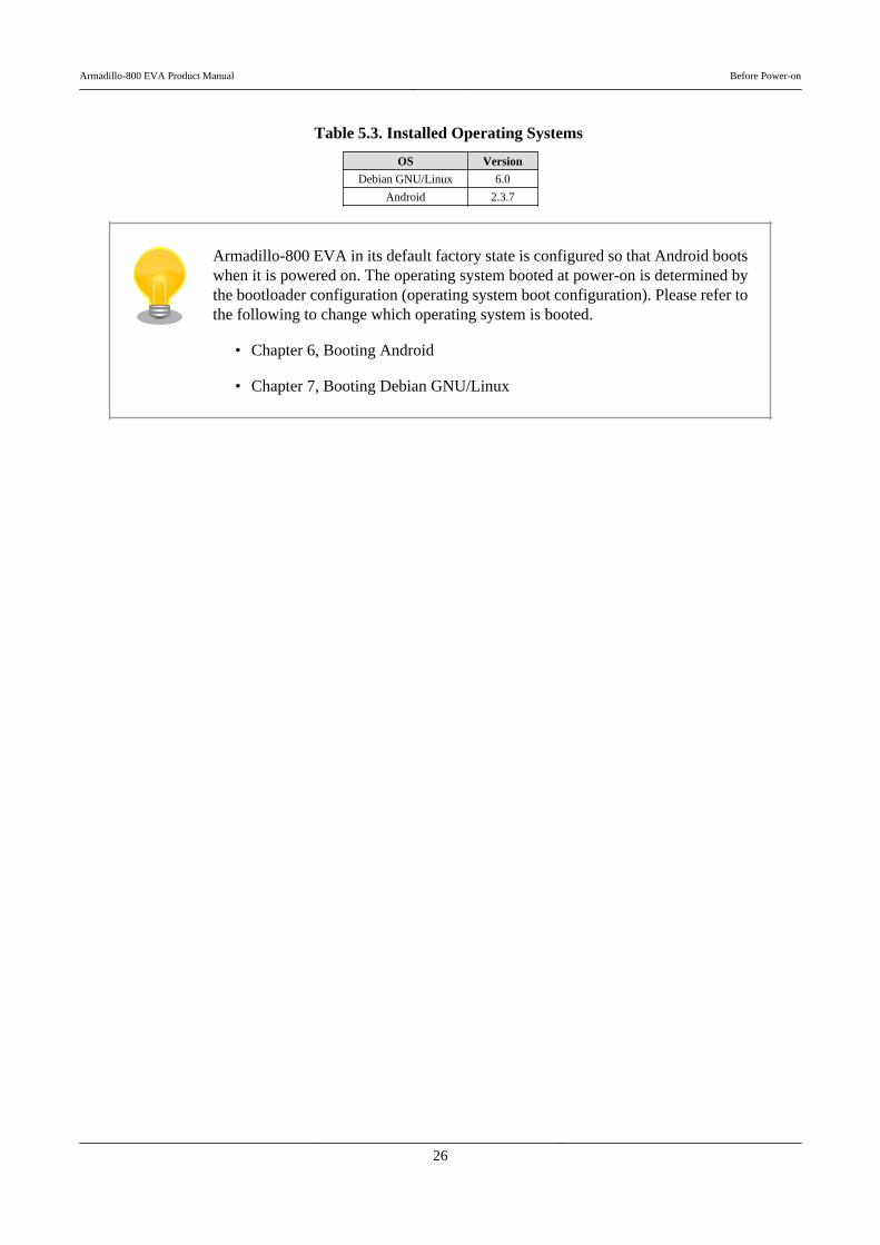
Table 5.3. Installed Operating Systems
OS Version
Debian GNU/Linux 6.0
Android 2.3.7
Armadillo-800 EVA in its default factory state is configured so that Android bootswhen it is powered on. The operating system booted at power-on is determined bythe bootloader configuration (operating system boot configuration). Please refer tothe following to change which operating system is booted.
• Chapter 6, Booting Android
• Chapter 7, Booting Debian GNU/Linux
Armadillo-800 EVA Product Manual Before Power-on
26

Chapter 6. Booting Android
6.1. PreparationThe following explains the changes made to the operating system boot configuration in order to boot Android.
The operating system booted can be changed by starting the bootloader in maintenance mode and altering the operatingsystem boot configuration. The bootloader will start in maintenance mode when the DIP switch boot mode configurationswitch (SW1.1) is first set to ON and the Armadillo-800 EVA then powered on.
Figure 6.1. DIP Switch Boot Mode Configuration
The bootloader command prompt is displayed when the bootloader is started in maintenance mode.
Hermit-At v3.0.0 (Armadillo-800 EVA) compiled at 22:22:10, Dec 21 2011hermit>
To boot Android, change the operating system boot configuration as shown in Figure 6.2, “Operating System BootConfiguration Change Procedure (Android)”.
hermit>setbootdevice mmcblk0p4 hermit>setenv console=ttySC1,115200 noinitrd rootwait root=/dev/mmcblk0p4 init=/ ⏎
init
Set the boot device in which the Linux kernel for Android is stored
Set the Linux kernel parameters
Figure 6.2. Operating System Boot Configuration Change Procedure (Android)
The changes to the operating system boot configuration are now complete. Android can now be booted with the bootcommand.
hermit>boot
Android will boot automatically after powering off the Armadillo-800 EVA, settingthe DIP switch boot mode configuration switch (SW1.1) to OFF and powering theArmadillo-800 EVA back on.
Armadillo-800 EVA Product Manual Booting Android
27

6.2. Booting
The boot log shown below will be displayed in the serial communication software when Android boots.
mmcsd: SD card at address 0x00000001mmcsd: M8G2FA 1048576KiBgendisk: /dev/mmcblk0p4: start=0x000f4280, size=0x001dcdc0gendisk: Image.bin is found. (4390496 Bytes)Copying kernel...done.Doing console=ttySC1,115200Doing noinitrdDoing rootwaitDoing root=/dev/mmcblk0p4Doing init=/initLinux version 2.6.35.7 (atmark@atde4) (gcc version 4.4.5 (Debian 4.4.5-8) ) #1 PREEMPT Wed Dec 21 22:37:47 JST 2011CPU: ARMv7 Processor [412fc093] revision 3 (ARMv7), cr=10c53c7fCPU: VIPT nonaliasing data cache, VIPT nonaliasing instruction cacheMachine: Armadillo-800EVA : : :VFS: Mounted root (ext3 filesystem) on device 179:4.Freeing init memory: 124Kinit: cannot open '/initlogo.rle'init: cannot find '/system/etc/install-recovery.sh', disabling 'flash_recovery'sh: can't access tty; job control turned off$ net eth0: attached phy 0 to driver Generic PHYWM8978 0-001a: Imprecise sampling rate: 48000Hz, consider using PLLPHY: 0:00 - Link is Up - 100/Fullwarning: `zygote' uses 32-bit capabilities (legacy support in use)request_suspend_state: wakeup (3->0) at 11694431586 (2000-01-01 00:12:25.651928834 UTC)
Figure 6.3. Boot Log (Android)
6.3. Shutdown
Follow the steps shown in Procedure 6.1, “Android Shutdown Procedure” to perform a safe shutdown.
This procedure is not supported by linux-2.6.35-a800eva-at1. To shutdown pleasejust cut the power supply. If power is cut while data is being written to a removabledisk, the file system or the data may be damaged.
Procedure 6.1. Android Shutdown Procedure
1. Press SW3 (power button) for an extended time.
2. Press "Power off" (red frame in diagram) in the "Phone options" screen.
Armadillo-800 EVA Product Manual Booting Android
28
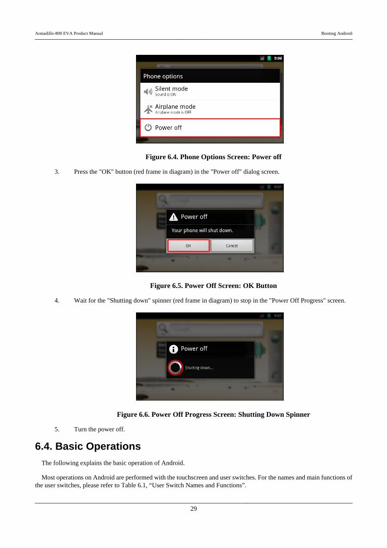
Figure 6.4. Phone Options Screen: Power off
3. Press the "OK" button (red frame in diagram) in the "Power off" dialog screen.
Figure 6.5. Power Off Screen: OK Button
4. Wait for the "Shutting down" spinner (red frame in diagram) to stop in the "Power Off Progress" screen.
Figure 6.6. Power Off Progress Screen: Shutting Down Spinner
5. Turn the power off.
6.4. Basic OperationsThe following explains the basic operation of Android.
Most operations on Android are performed with the touchscreen and user switches. For the names and main functions ofthe user switches, please refer to Table 6.1, “User Switch Names and Functions”.
Armadillo-800 EVA Product Manual Booting Android
29

Table 6.1. User Switch Names and Functions
User Switch Name Main Function
SW3 Power Button Move to lock screen / shut down safely
SW4 Back Button Return to the previous screen
SW5 Menu Button Open the menu
SW6 Home Button Move to the home screen
SW3 was assigned as the select button in linux-2.6.35-a800eva-at1. This waschanged to the power button from linux-2.6.35-a800eva-at2. The select button isused to activate the currently focused key.
6.4.1. Lock Screen
When the "Power Button" is pressed immediately after booting Android or while in any screen apart from the lock screen,Figure 6.7, “Lock Screen” will be displayed.
Figure 6.7. Lock Screen
The lock can be released by pressing the "Menu Button" twice. When this is done immediately after booting Android,the home screen shown in Section 6.4.2, “Home Screen” will be displayed.
The lock screen will be displayed if no operation is made for a fixed period of time while any other screen is beingdisplayed.
6.4.2. Home Screen
When the "Home Button" is pressed in any screen apart from the lock screen, Figure 6.8, “Home Screen” will be displayed.
Armadillo-800 EVA Product Manual Booting Android
30
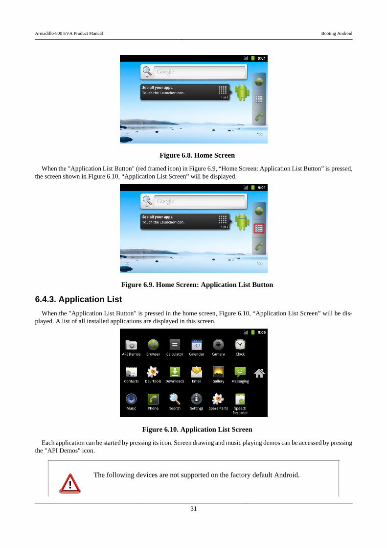
Figure 6.8. Home Screen
When the "Application List Button" (red framed icon) in Figure 6.9, “Home Screen: Application List Button” is pressed,the screen shown in Figure 6.10, “Application List Screen” will be displayed.
Figure 6.9. Home Screen: Application List Button
6.4.3. Application List
When the "Application List Button" is pressed in the home screen, Figure 6.10, “Application List Screen” will be dis-played. A list of all installed applications are displayed in this screen.
Figure 6.10. Application List Screen
Each application can be started by pressing its icon. Screen drawing and music playing demos can be accessed by pressingthe "API Demos" icon.
The following devices are not supported on the factory default Android.
Armadillo-800 EVA Product Manual Booting Android
31

• Camera• Wireless LAN• SD Card
The Android source code[1] can be obtained from the Armadillo Site (http://arma-dillo.atmark-techno.com).
[1]Software with usage restrictions is not included.
Armadillo-800 EVA Product Manual Booting Android
32
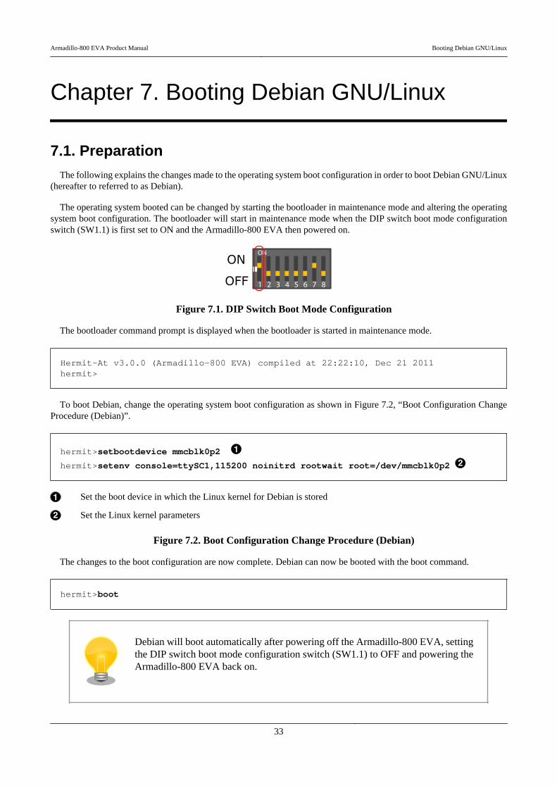
Chapter 7. Booting Debian GNU/Linux
7.1. PreparationThe following explains the changes made to the operating system boot configuration in order to boot Debian GNU/Linux
(hereafter to referred to as Debian).
The operating system booted can be changed by starting the bootloader in maintenance mode and altering the operatingsystem boot configuration. The bootloader will start in maintenance mode when the DIP switch boot mode configurationswitch (SW1.1) is first set to ON and the Armadillo-800 EVA then powered on.
Figure 7.1. DIP Switch Boot Mode Configuration
The bootloader command prompt is displayed when the bootloader is started in maintenance mode.
Hermit-At v3.0.0 (Armadillo-800 EVA) compiled at 22:22:10, Dec 21 2011hermit>
To boot Debian, change the operating system boot configuration as shown in Figure 7.2, “Boot Configuration ChangeProcedure (Debian)”.
hermit>setbootdevice mmcblk0p2
hermit>setenv console=ttySC1,115200 noinitrd rootwait root=/dev/mmcblk0p2
Set the boot device in which the Linux kernel for Debian is stored
Set the Linux kernel parameters
Figure 7.2. Boot Configuration Change Procedure (Debian)
The changes to the boot configuration are now complete. Debian can now be booted with the boot command.
hermit>boot
Debian will boot automatically after powering off the Armadillo-800 EVA, settingthe DIP switch boot mode configuration switch (SW1.1) to OFF and powering theArmadillo-800 EVA back on.
Armadillo-800 EVA Product Manual Booting Debian GNU/Linux
33
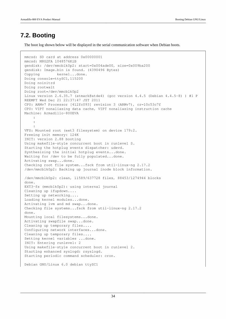
7.2. BootingThe boot log shown below will be displayed in the serial communication software when Debian boots.
mmcsd: SD card at address 0x00000001mmcsd: M8G2FA 1048576KiBgendisk: /dev/mmcblk0p2: start=0x004ade00, size=0x009ba200gendisk: Image.bin is found. (4390496 Bytes)Copying kernel...done.Doing console=ttySC1,115200Doing noinitrdDoing rootwaitDoing root=/dev/mmcblk0p2Linux version 2.6.35.7 (atmark@atde4) (gcc version 4.4.5 (Debian 4.4.5-8) ) #1 PREEMPT Wed Dec 21 22:37:47 JST 2011CPU: ARMv7 Processor [412fc093] revision 3 (ARMv7), cr=10c53c7fCPU: VIPT nonaliasing data cache, VIPT nonaliasing instruction cacheMachine: Armadillo-800EVA : : :VFS: Mounted root (ext3 filesystem) on device 179:2.Freeing init memory: 124KINIT: version 2.88 bootingUsing makefile-style concurrent boot in runlevel S.Starting the hotplug events dispatcher: udevd.Synthesizing the initial hotplug events...done.Waiting for /dev to be fully populated...done.Activating swap...done.Checking root file system...fsck from util-linux-ng 2.17.2/dev/mmcblk0p2: Backing up journal inode block information.
/dev/mmcblk0p2: clean, 11589/637728 files, 88453/1274944 blocksdone.EXT3-fs (mmcblk0p2): using internal journalCleaning up ifupdown....Setting up networking....Loading kernel modules...done.Activating lvm and md swap...done.Checking file systems...fsck from util-linux-ng 2.17.2done.Mounting local filesystems...done.Activating swapfile swap...done.Cleaning up temporary files....Configuring network interfaces...done.Cleaning up temporary files....Setting kernel variables ...done.INIT: Entering runlevel: 2Using makefile-style concurrent boot in runlevel 2.Starting enhanced syslogd: rsyslogd.Starting periodic command scheduler: cron.
Debian GNU/Linux 6.0 debian ttySC1
Armadillo-800 EVA Product Manual Booting Debian GNU/Linux
34

debian login:
Figure 7.3. Boot Log (Linux)
7.3. LoginThe login prompt will be displayed once the boot has completed. The users shown in Table 7.1, “Serial Console Login
Username and Password” can be used to login.
Table 7.1. Serial Console Login Username and Password
Username Password Permissions
root root root user
7.4. ShutdownTo perform a safe shutdown, execute the halt command as shown below, wait until the "System halted." message is
displayed and then disconnect the power supply.
[armadillo ~]# halt
Broadcast message from root@debian (ttySC1) (Sat Jan 1 04:25:31 2000):
The system is going down for system halt NOW!INIT: Switching to runlevel: 0INIT: Sending processes the TERM signalUsing makefile-style concurrent boot in runlevel 0.Asking all remaining processes to terminate...done.All processes ended within 1 seconds....done.Stopping enhanced syslogd: rsyslogd.Deconfiguring network interfaces...done.Cleaning up ifupdown....Saving the system clock.Deactivating swap...done.Will now halt.System halted.
Figure 7.4. Shutdown
Armadillo-800 EVA Product Manual Booting Debian GNU/Linux
35
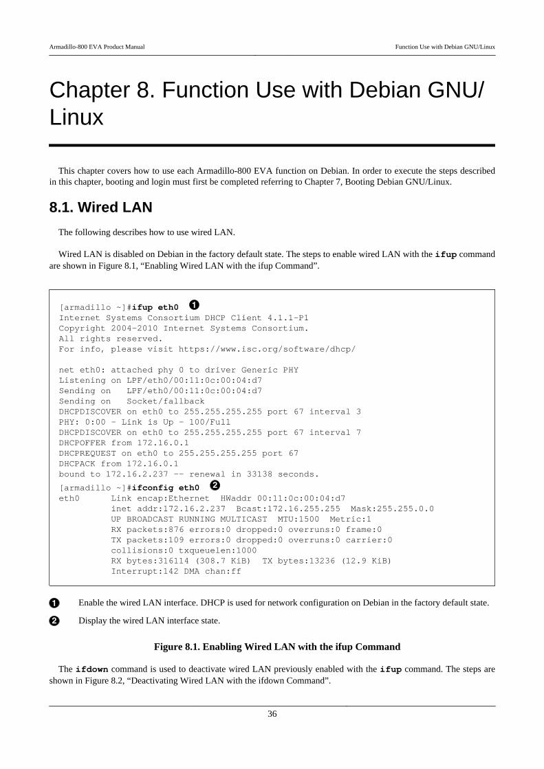
Chapter 8. Function Use with Debian GNU/Linux
This chapter covers how to use each Armadillo-800 EVA function on Debian. In order to execute the steps describedin this chapter, booting and login must first be completed referring to Chapter 7, Booting Debian GNU/Linux.
8.1. Wired LAN
The following describes how to use wired LAN.
Wired LAN is disabled on Debian in the factory default state. The steps to enable wired LAN with the ifup commandare shown in Figure 8.1, “Enabling Wired LAN with the ifup Command”.
[armadillo ~]#ifup eth0 Internet Systems Consortium DHCP Client 4.1.1-P1Copyright 2004-2010 Internet Systems Consortium.All rights reserved.For info, please visit https://www.isc.org/software/dhcp/
net eth0: attached phy 0 to driver Generic PHYListening on LPF/eth0/00:11:0c:00:04:d7Sending on LPF/eth0/00:11:0c:00:04:d7Sending on Socket/fallbackDHCPDISCOVER on eth0 to 255.255.255.255 port 67 interval 3PHY: 0:00 - Link is Up - 100/FullDHCPDISCOVER on eth0 to 255.255.255.255 port 67 interval 7DHCPOFFER from 172.16.0.1DHCPREQUEST on eth0 to 255.255.255.255 port 67DHCPACK from 172.16.0.1bound to 172.16.2.237 -- renewal in 33138 seconds.
[armadillo ~]#ifconfig eth0 eth0 Link encap:Ethernet HWaddr 00:11:0c:00:04:d7 inet addr:172.16.2.237 Bcast:172.16.255.255 Mask:255.255.0.0 UP BROADCAST RUNNING MULTICAST MTU:1500 Metric:1 RX packets:876 errors:0 dropped:0 overruns:0 frame:0 TX packets:109 errors:0 dropped:0 overruns:0 carrier:0 collisions:0 txqueuelen:1000 RX bytes:316114 (308.7 KiB) TX bytes:13236 (12.9 KiB) Interrupt:142 DMA chan:ff
Enable the wired LAN interface. DHCP is used for network configuration on Debian in the factory default state.
Display the wired LAN interface state.
Figure 8.1. Enabling Wired LAN with the ifup Command
The ifdown command is used to deactivate wired LAN previously enabled with the ifup command. The steps areshown in Figure 8.2, “Deactivating Wired LAN with the ifdown Command”.
Armadillo-800 EVA Product Manual Function Use with Debian GNU/Linux
36
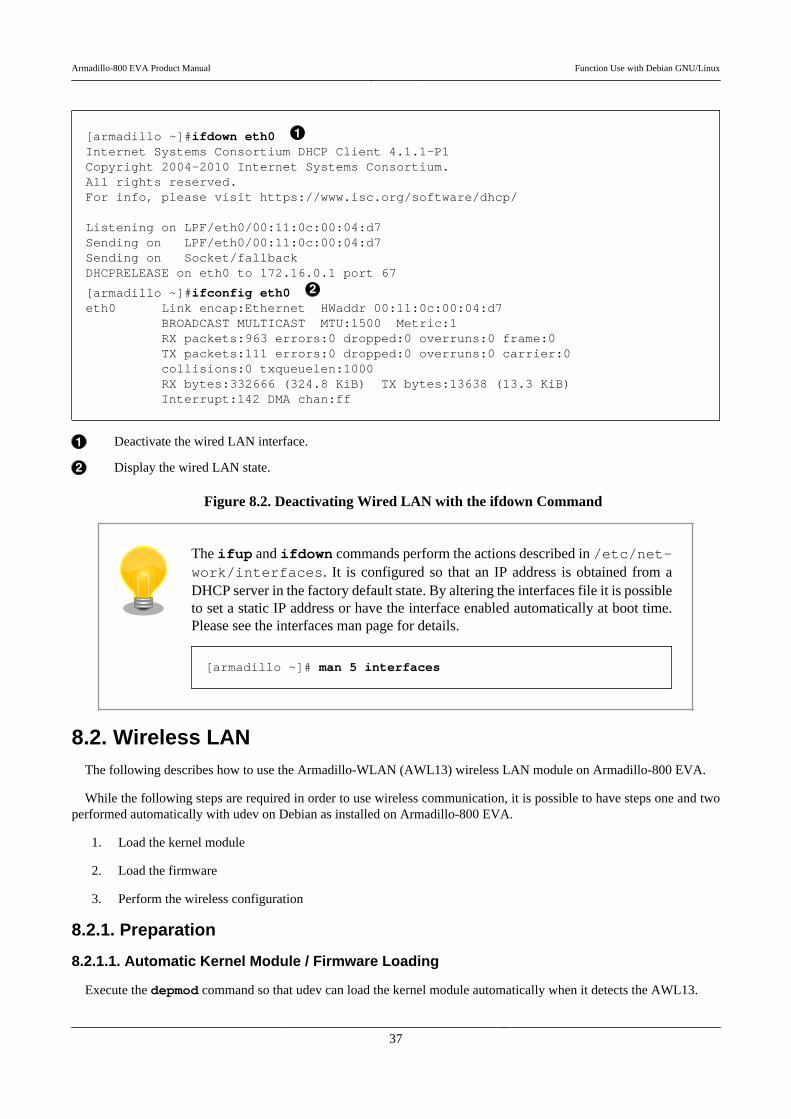
[armadillo ~]#ifdown eth0 Internet Systems Consortium DHCP Client 4.1.1-P1Copyright 2004-2010 Internet Systems Consortium.All rights reserved.For info, please visit https://www.isc.org/software/dhcp/
Listening on LPF/eth0/00:11:0c:00:04:d7Sending on LPF/eth0/00:11:0c:00:04:d7Sending on Socket/fallbackDHCPRELEASE on eth0 to 172.16.0.1 port 67
[armadillo ~]#ifconfig eth0 eth0 Link encap:Ethernet HWaddr 00:11:0c:00:04:d7 BROADCAST MULTICAST MTU:1500 Metric:1 RX packets:963 errors:0 dropped:0 overruns:0 frame:0 TX packets:111 errors:0 dropped:0 overruns:0 carrier:0 collisions:0 txqueuelen:1000 RX bytes:332666 (324.8 KiB) TX bytes:13638 (13.3 KiB) Interrupt:142 DMA chan:ff
Deactivate the wired LAN interface.
Display the wired LAN state.
Figure 8.2. Deactivating Wired LAN with the ifdown Command
The ifup and ifdown commands perform the actions described in /etc/net-work/interfaces. It is configured so that an IP address is obtained from aDHCP server in the factory default state. By altering the interfaces file it is possibleto set a static IP address or have the interface enabled automatically at boot time.Please see the interfaces man page for details.
[armadillo ~]# man 5 interfaces
8.2. Wireless LANThe following describes how to use the Armadillo-WLAN (AWL13) wireless LAN module on Armadillo-800 EVA.
While the following steps are required in order to use wireless communication, it is possible to have steps one and twoperformed automatically with udev on Debian as installed on Armadillo-800 EVA.
1. Load the kernel module
2. Load the firmware
3. Perform the wireless configuration
8.2.1. Preparation
8.2.1.1. Automatic Kernel Module / Firmware Loading
Execute the depmod command so that udev can load the kernel module automatically when it detects the AWL13.
Armadillo-800 EVA Product Manual Function Use with Debian GNU/Linux
37

[armadillo ~]#ls /lib/modules/$(uname -r)awl13[armadillo ~]#depmod[armadillo ~]#ls /lib/modules/$(uname -r)awl13 modules.dep modules.softdepmodules.alias modules.dep.bin modules.symbolsmodules.alias.bin modules.devname modules.symbols.bin
The kernel module will be loaded automatically after rebooting. Execute the reboot command to perform a reboot.
[armadillo ~]#reboot
Once the kernel module is loaded, udev will automatically load the firmware. The following will appear in the boot logonce the kernel module and firmware have been successfully loaded.
awl13: Version 3.0.0 Load.awl13: MAC is 00:1d:12:cf:29:65
After executing the depmod command, to have the AWL13 detected by udev with-out rebooting Armadillo-800 EVA execute the following command.
[armadillo ~]# udevadm trigger
If the kernel module does not load, please check the configuration of SW1 (DIPswitch) referring to Section 5.3, “DIP Switch Configuration”. Only either one ofCON14 (AWL13 Module Interface) and CON8 (SD2 Interface) can be used at anyone time. To use AWL13, please set the SDHI1 configuration (SW1.5) on the DIPswitch to off.
8.2.2. Wireless Configuration
The following covers infrastructure mode and ad-hoc mode wireless configuration. For more detailed information, pleaserefer to the "Armadillo-WLAN (AWL13) Software Manual".
When connected to a network using the wired LAN interface, the AWL13 may notbe used for network transmission. In order to ensure that wireless transmission isused, please deactivate the wired LAN interface by referring to Figure 8.2, “Deac-tivating Wired LAN with the ifdown Command”.
Wireless LAN transmission may become unstable due to the operating environment.In these environments, the problem can sometimes be resolved by attaching an
Armadillo-800 EVA Product Manual Function Use with Debian GNU/Linux
38
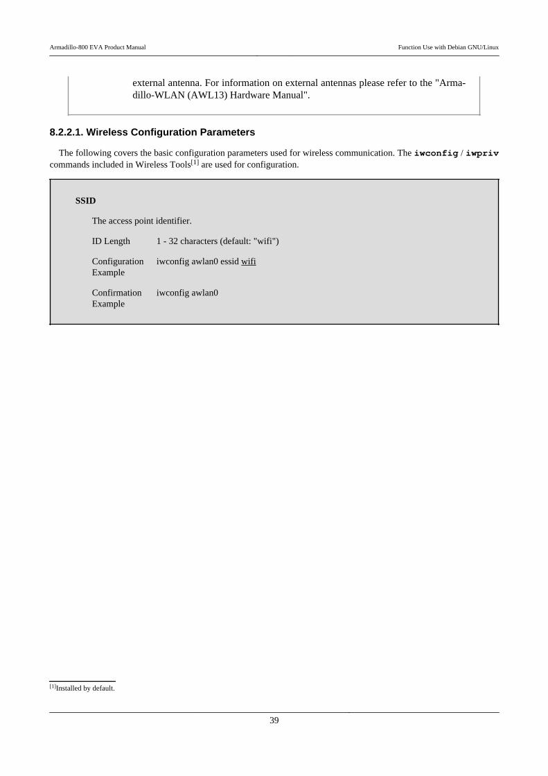
external antenna. For information on external antennas please refer to the "Arma-dillo-WLAN (AWL13) Hardware Manual".
8.2.2.1. Wireless Configuration Parameters
The following covers the basic configuration parameters used for wireless communication. The iwconfig / iwprivcommands included in Wireless Tools[1] are used for configuration.
SSID
The access point identifier.
ID Length 1 - 32 characters (default: "wifi")
ConfigurationExample
iwconfig awlan0 essid wifi
ConfirmationExample
iwconfig awlan0
[1]Installed by default.
Armadillo-800 EVA Product Manual Function Use with Debian GNU/Linux
39
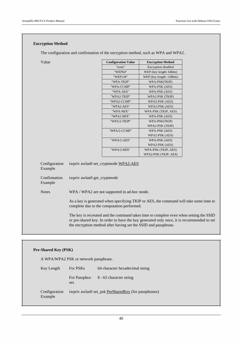
Encryption Method
The configuration and confirmation of the encryption method, such as WPA and WPA2.
Value Configuration Value Encryption Method
"none" Encryption disabled
"WEP64" WEP (key length: 64bits)
"WEP128" WEP (key length: 128bits)
"WPA-TKIP" WPA-PSK(TKIP)
"WPA-CCMP" WPA-PSK (AES)
"WPA-AES" WPA-PSK (AES)
"WPA2-TKIP" WPA2-PSK (TKIP)
"WPA2-CCMP" WPA2-PSK (AES)
"WPA2-AES" WPA2-PSK (AES)
"WPA-MIX" WPA-PSK (TKIP, AES)
"WPA2-MIX" WPA-PSK (AES)
"WPA/2-TKIP" WPA-PSK(TKIP)
WPA2-PSK (TKIP)
"WPA/2-CCMP" WPA-PSK (AES)
WPA2-PSK (AES)
"WPA/2-AES" WPA-PSK (AES)
WPA2-PSK (AES)
"WPA/2-MIX" WPA-PSK (TKIP, AES)
WPA2-PSK (TKIP, AES)
ConfigurationExample
iwpriv awlan0 set_cryptmode WPA2-AES
ConfirmationExample
iwpriv awlan0 get_cryptmode
Notes WPA / WPA2 are not supported in ad-hoc mode.
As a key is generated when specifying TKIP or AES, the command will take some time tocomplete due to the computation performed.
The key is recreated and the command takes time to complete even when setting the SSIDor pre-shared key. In order to have the key generated only once, it is recommended to setthe encryption method after having set the SSID and passphrase.
Pre-Shared Key (PSK)
A WPA/WPA2 PSK or network passphrase.
Key Length For PSKs 64 character hexadecimal string
For Passphra-ses
8 - 63 character string
ConfigurationExample
iwpriv awlan0 set_psk PreSharedKey (for passphrases)
Armadillo-800 EVA Product Manual Function Use with Debian GNU/Linux
40
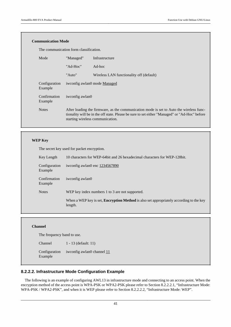
Communication Mode
The communication form classification.
Mode "Managed" Infrastructure
"Ad-Hoc" Ad-hoc
"Auto" Wireless LAN functionality off (default)
ConfigurationExample
iwconfig awlan0 mode Managed
ConfirmationExample
iwconfig awlan0
Notes After loading the firmware, as the communication mode is set to Auto the wireless func-tionality will be in the off state. Please be sure to set either "Managed" or "Ad-Hoc" beforestarting wireless communication.
WEP Key
The secret key used for packet encryption.
Key Length 10 characters for WEP-64bit and 26 hexadecimal characters for WEP-128bit.
ConfigurationExample
iwconfig awlan0 enc 1234567890
ConfirmationExample
iwconfig awlan0
Notes WEP key index numbers 1 to 3 are not supported.
When a WEP key is set, Encryption Method is also set appropriately according to the keylength.
Channel
The frequency band to use.
Channel 1 - 13 (default: 11)
ConfigurationExample
iwconfig awlan0 channel 11
8.2.2.2. Infrastructure Mode Configuration Example
The following is an example of configuring AWL13 in infrastructure mode and connecting to an access point. When theencryption method of the access point is WPA-PSK or WPA2-PSK please refer to Section 8.2.2.2.1, “Infrastructure Mode:WPA-PSK / WPA2-PSK”, and when it is WEP please refer to Section 8.2.2.2.2, “Infrastructure Mode: WEP”.
Armadillo-800 EVA Product Manual Function Use with Debian GNU/Linux
41
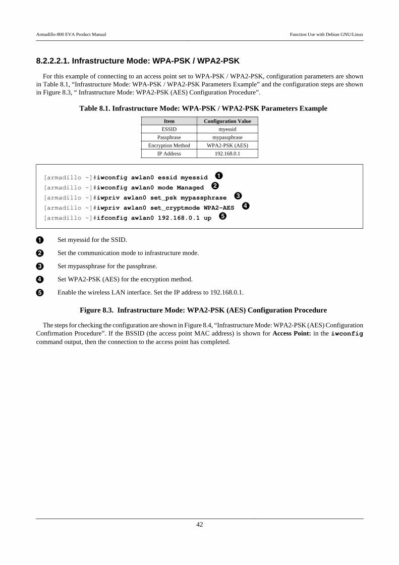
8.2.2.2.1. Infrastructure Mode: WPA-PSK / WPA2-PSK
For this example of connecting to an access point set to WPA-PSK / WPA2-PSK, configuration parameters are shownin Table 8.1, “Infrastructure Mode: WPA-PSK / WPA2-PSK Parameters Example” and the configuration steps are shownin Figure 8.3, “ Infrastructure Mode: WPA2-PSK (AES) Configuration Procedure”.
Table 8.1. Infrastructure Mode: WPA-PSK / WPA2-PSK Parameters Example
Item Configuration Value
ESSID myessid
Passphrase mypassphrase
Encryption Method WPA2-PSK (AES)
IP Address 192.168.0.1
[armadillo ~]#iwconfig awlan0 essid myessid
[armadillo ~]#iwconfig awlan0 mode Managed
[armadillo ~]#iwpriv awlan0 set_psk mypassphrase
[armadillo ~]#iwpriv awlan0 set_cryptmode WPA2-AES
[armadillo ~]#ifconfig awlan0 192.168.0.1 up
Set myessid for the SSID.
Set the communication mode to infrastructure mode.
Set mypassphrase for the passphrase.
Set WPA2-PSK (AES) for the encryption method.
Enable the wireless LAN interface. Set the IP address to 192.168.0.1.
Figure 8.3. Infrastructure Mode: WPA2-PSK (AES) Configuration Procedure
The steps for checking the configuration are shown in Figure 8.4, “Infrastructure Mode: WPA2-PSK (AES) ConfigurationConfirmation Procedure”. If the BSSID (the access point MAC address) is shown for Access Point: in the iwconfigcommand output, then the connection to the access point has completed.
Armadillo-800 EVA Product Manual Function Use with Debian GNU/Linux
42
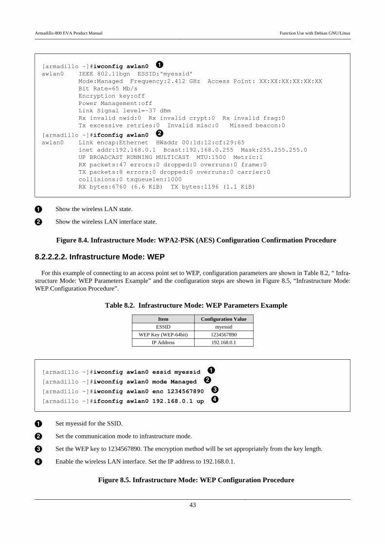
[armadillo ~]#iwconfig awlan0 awlan0 IEEE 802.11bgn ESSID:"myessid" Mode:Managed Frequency:2.412 GHz Access Point: XX:XX:XX:XX:XX:XX Bit Rate=65 Mb/s Encryption key:off Power Management:off Link Signal level=-37 dBm Rx invalid nwid:0 Rx invalid crypt:0 Rx invalid frag:0 Tx excessive retries:0 Invalid misc:0 Missed beacon:0
[armadillo ~]#ifconfig awlan0 awlan0 Link encap:Ethernet HWaddr 00:1d:12:cf:29:65 inet addr:192.168.0.1 Bcast:192.168.0.255 Mask:255.255.255.0 UP BROADCAST RUNNING MULTICAST MTU:1500 Metric:1 RX packets:47 errors:0 dropped:0 overruns:0 frame:0 TX packets:8 errors:0 dropped:0 overruns:0 carrier:0 collisions:0 txqueuelen:1000 RX bytes:6760 (6.6 KiB) TX bytes:1196 (1.1 KiB)
Show the wireless LAN state.
Show the wireless LAN interface state.
Figure 8.4. Infrastructure Mode: WPA2-PSK (AES) Configuration Confirmation Procedure
8.2.2.2.2. Infrastructure Mode: WEP
For this example of connecting to an access point set to WEP, configuration parameters are shown in Table 8.2, “ Infra-structure Mode: WEP Parameters Example” and the configuration steps are shown in Figure 8.5, “Infrastructure Mode:WEP Configuration Procedure”.
Table 8.2. Infrastructure Mode: WEP Parameters Example
Item Configuration Value
ESSID myessid
WEP Key (WEP-64bit) 1234567890
IP Address 192.168.0.1
[armadillo ~]#iwconfig awlan0 essid myessid
[armadillo ~]#iwconfig awlan0 mode Managed
[armadillo ~]#iwconfig awlan0 enc 1234567890
[armadillo ~]#ifconfig awlan0 192.168.0.1 up
Set myessid for the SSID.
Set the communication mode to infrastructure mode.
Set the WEP key to 1234567890. The encryption method will be set appropriately from the key length.
Enable the wireless LAN interface. Set the IP address to 192.168.0.1.
Figure 8.5. Infrastructure Mode: WEP Configuration Procedure
Armadillo-800 EVA Product Manual Function Use with Debian GNU/Linux
43
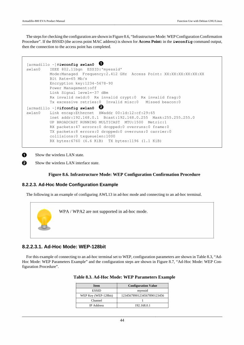
The steps for checking the configuration are shown in Figure 8.6, “Infrastructure Mode: WEP Configuration ConfirmationProcedure”. If the BSSID (the access point MAC address) is shown for Access Point: in the iwconfig command output,then the connection to the access point has completed.
[armadillo ~]#iwconfig awlan0 awlan0 IEEE 802.11bgn ESSID:"myessid" Mode:Managed Frequency:2.412 GHz Access Point: XX:XX:XX:XX:XX:XX Bit Rate=65 Mb/s Encryption key:1234-5678-90 Power Management:off Link Signal level=-37 dBm Rx invalid nwid:0 Rx invalid crypt:0 Rx invalid frag:0 Tx excessive retries:0 Invalid misc:0 Missed beacon:0
[armadillo ~]#ifconfig awlan0 awlan0 Link encap:Ethernet HWaddr 00:1d:12:cf:29:65 inet addr:192.168.0.1 Bcast:192.168.0.255 Mask:255.255.255.0 UP BROADCAST RUNNING MULTICAST MTU:1500 Metric:1 RX packets:47 errors:0 dropped:0 overruns:0 frame:0 TX packets:8 errors:0 dropped:0 overruns:0 carrier:0 collisions:0 txqueuelen:1000 RX bytes:6760 (6.6 KiB) TX bytes:1196 (1.1 KiB)
Show the wireless LAN state.
Show the wireless LAN interface state.
Figure 8.6. Infrastructure Mode: WEP Configuration Confirmation Procedure
8.2.2.3. Ad-Hoc Mode Configuration Example
The following is an example of configuring AWL13 in ad-hoc mode and connecting to an ad-hoc terminal.
WPA / WPA2 are not supported in ad-hoc mode.
8.2.2.3.1. Ad-Hoc Mode: WEP-128bit
For this example of connecting to an ad-hoc terminal set to WEP, configuration parameters are shown in Table 8.3, “Ad-Hoc Mode: WEP Parameters Example” and the configuration steps are shown in Figure 8.7, “Ad-Hoc Mode: WEP Con-figuration Procedure”.
Table 8.3. Ad-Hoc Mode: WEP Parameters Example
Item Configuration Value
ESSID myessid
WEP Key (WEP-128bit) 12345678901234567890123456
Channel 1
IP Address 192.168.0.1
Armadillo-800 EVA Product Manual Function Use with Debian GNU/Linux
44
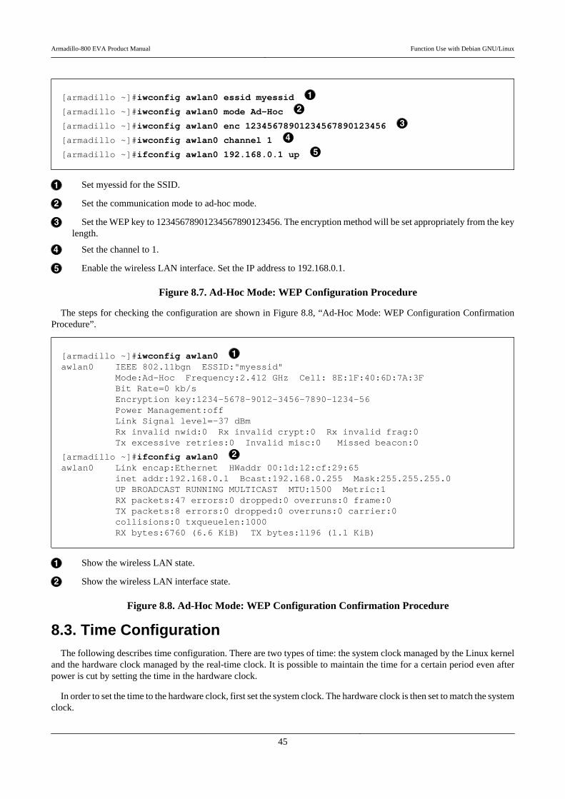
[armadillo ~]#iwconfig awlan0 essid myessid
[armadillo ~]#iwconfig awlan0 mode Ad-Hoc
[armadillo ~]#iwconfig awlan0 enc 12345678901234567890123456
[armadillo ~]#iwconfig awlan0 channel 1
[armadillo ~]#ifconfig awlan0 192.168.0.1 up
Set myessid for the SSID.
Set the communication mode to ad-hoc mode.
Set the WEP key to 12345678901234567890123456. The encryption method will be set appropriately from the keylength.
Set the channel to 1.
Enable the wireless LAN interface. Set the IP address to 192.168.0.1.
Figure 8.7. Ad-Hoc Mode: WEP Configuration Procedure
The steps for checking the configuration are shown in Figure 8.8, “Ad-Hoc Mode: WEP Configuration ConfirmationProcedure”.
[armadillo ~]#iwconfig awlan0 awlan0 IEEE 802.11bgn ESSID:"myessid" Mode:Ad-Hoc Frequency:2.412 GHz Cell: 8E:1F:40:6D:7A:3F Bit Rate=0 kb/s Encryption key:1234-5678-9012-3456-7890-1234-56 Power Management:off Link Signal level=-37 dBm Rx invalid nwid:0 Rx invalid crypt:0 Rx invalid frag:0 Tx excessive retries:0 Invalid misc:0 Missed beacon:0
[armadillo ~]#ifconfig awlan0 awlan0 Link encap:Ethernet HWaddr 00:1d:12:cf:29:65 inet addr:192.168.0.1 Bcast:192.168.0.255 Mask:255.255.255.0 UP BROADCAST RUNNING MULTICAST MTU:1500 Metric:1 RX packets:47 errors:0 dropped:0 overruns:0 frame:0 TX packets:8 errors:0 dropped:0 overruns:0 carrier:0 collisions:0 txqueuelen:1000 RX bytes:6760 (6.6 KiB) TX bytes:1196 (1.1 KiB)
Show the wireless LAN state.
Show the wireless LAN interface state.
Figure 8.8. Ad-Hoc Mode: WEP Configuration Confirmation Procedure
8.3. Time ConfigurationThe following describes time configuration. There are two types of time: the system clock managed by the Linux kernel
and the hardware clock managed by the real-time clock. It is possible to maintain the time for a certain period even afterpower is cut by setting the time in the hardware clock.
In order to set the time to the hardware clock, first set the system clock. The hardware clock is then set to match the systemclock.
Armadillo-800 EVA Product Manual Function Use with Debian GNU/Linux
45

[armadillo ~]#date 010609002012
[armadillo ~]#date Fri Jan 6 09:00:05 UTC 2012
Set the system clock to 9:00 on January 6, 2012[2].
Check the system clock.
Figure 8.9. System Clock Configuration
[armadillo ~]#hwclock -wu
[armadillo ~]#hwclock Fri Jan 6 09:00:14 2012 -0.319894 seconds
Set the hardware clock from the system clock.
Check the hardware clock.
Figure 8.10. Hardware Clock Configuration
Once the real-time clock is set, as the system clock is set from the real-time clock value when Debian is booted afterpowering off and on there is no need to set the system clock again. When powering off for an extended period of time, abattery must be connected to the RTC external backup interface (CON9).
8.4. Package ManagementThe following describes how to manage packages with the APT (Advanced Packaging Tool) package management sys-
tem. While only the bare minimum of packages required for Debian to operate are installed in the factory default state, it ispossible to easily add packages using APT.
In the factory default state, APT obtains indexes of usable packages from Debian sites (HTTP servers) on the internet[3].Therefore in order to use APT, networking must be enabled and the internet accessible.
For information on enabling networking, please refer to Section 8.1, “Wired LAN” and Section 8.2, “Wireless LAN”.
When the system clock is incorrect by a large margin, warning messages may appearwhen using APT. Please correct the system clock beforehand by referring to Sec-tion 8.3, “Time Configuration”.
[2]The format is MMDDhhmm[[CC]YY][.ss]. For details, please refer to the date man page.[3]This is configured in /etc/apt/sources.list. For configuration details, please refer to the sources.list man page.
Armadillo-800 EVA Product Manual Function Use with Debian GNU/Linux
46

apt-get update
Update the package index files to the latest versions.
Arguments None
Usage Exam-ple [armadillo ~]#apt-get update
apt-get upgrade
Upgrade all currently installed packages to the latest versions.
Arguments None
Usage Exam-ple [armadillo ~]#apt-get upgrade
apt-get install [package name]
Install the package specified in the argument. The package will be upgraded if it is already installed.
Arguments Package name (multiple possible)
Usage Exam-ple [armadillo ~]#apt-get install gcc
apt-get remove [package name]
Uninstall the package specified in the argument. Nothing will occur if the package is not currently installed.
Arguments Package name (multiple possible)
Usage Exam-ple [armadillo ~]#apt-get remove apache2
Armadillo-800 EVA Product Manual Function Use with Debian GNU/Linux
47
apt-cache search [keyword]
Search for packages which include the specified keyword in their package name or description.
Arguments Keyword (regular expressions supported)
Usage Exam-ple [armadillo ~]#apt-cache search "Bourne Again SHell"
bash-doc - Documentation and examples for the The GNU ⏎Bourne Again SHellbash-static - The GNU Bourne Again SHell (static version)bash - The GNU Bourne Again SHell
8.5. GStreamer
The following describes how to install and use GStreamer.
GStreamer is an open source multimedia framework. It provides base functionality for multimedia applications that useaudio and video.
The gst-launch command is available with GStreamer to perform validation. With gst-launch it is possible touse GStreamer functionality without creating a program.
gst-launch can be used to try the following functionality.
• Section 8.7, “Video”• Section 8.8, “Camera”• Section 8.9, “Audio”
8.5.1. Installing GStreamer
Use APT to install GStreamer. For information on using APT, please refer to Section 8.4, “Package Management”.
Execute the following command to install GStreamer with APT.
[armadillo ~]#apt-get install gstreamer0.10 gstreamer-tools
Figure 8.11. Installing GStreamer
8.5.2. Using GStreamer
In this section the gst-launch command is used to operate GStreamer.
With GStreamer, elements with specific functionality are linked to create the desired functionality. With gst-launch, elements are linked using exclamation marks.
Elements have pads which can either input or output multimedia data. Elements are clasified into three types dependingon the pads they have.
Armadillo-800 EVA Product Manual Function Use with Debian GNU/Linux
48
Table 8.4. Element Types
Element Explanation
Source Elements Elements with only output pads.
Filter Elements Elements with at least one input and one output pad.
Sink Elements Elements with only input pads.
Below shows an example using gst-launch with only a source element and a sink element.
[armadillo ~]#gst-launch audiotestsrc ! alsasink
Figure 8.12. Playing Test Audio
audiotestsrc is a source element that generates test audio (with a 440Hz sine wave). alsasink is a sink element that outputsaudio to an ALSA device. By linking these two elements test audio is output to an ALSA device.
Armadillo-800 EVA does not support the test audio format that is generated from audiotestsrc by default. An examplewhere audiotestsrc properties are specified to output test audio from headphones connected to the stereo headphone output(CON11) on Armadillo-800 EVA is shown below.
[armadillo ~]#gst-launch -v audiotestsrc ! 'audio/x-raw-int,channels=2,width=16' ! ⏎alsasink
Figure 8.13. Playing Test Audio on Armadillo-800 EVA
For more detailed information on GStreamer, please refer to the official GStreamer site (http://gstreamer.freedesk-top.org/).
8.6. X ServerThe following describes how to install and start X Server.
X Server can be used to try the following functionality.
• Section 8.7, “Video”• Section 8.8, “Camera”
8.6.1. Installing X Server
Use APT to install the X server. For information on using APT, please refer to Section 8.4, “Package Management”.
Execute the following command to install the X server with APT.
[armadillo ~]#apt-get install xserver-xorg-core
Figure 8.14. Installing X Server
8.6.2. Starting X Server
The following describes how to start the X server specifying which video output the X server should use. The videooutputs supported on Armadillo-800 EVA are as shown below.
Armadillo-800 EVA Product Manual Function Use with Debian GNU/Linux
49
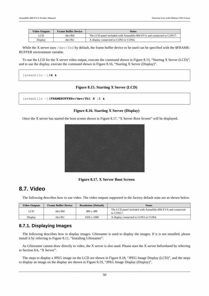
Video Outputs Frame Buffer Device Notes
LCD /dev/fb0 The LCD panel included with Armadillo-800 EVA and connected to CON17.
Display /dev/fb1 A display connected to CON3 or CON4.
While the X server uses /dev/fb0 by default, the frame buffer device to be used can be specified with the $FRAME-BUFFER environment variable.
To use the LCD for the X server video output, execute the command shown in Figure 8.15, “Starting X Server (LCD)”,and to use the display, execute the command shown in Figure 8.16, “Starting X Server (Display)”.
[armadillo ~]#X &
Figure 8.15. Starting X Server (LCD)
[armadillo ~]#FRAMEBUFFER=/dev/fb1 X :1 &
Figure 8.16. Starting X Server (Display)
Once the X server has started the boot screen shown in Figure 8.17, “X Server Boot Screen” will be displayed.
Figure 8.17. X Server Boot Screen
8.7. VideoThe following describes how to use video. The video outputs supported in the factory default state are as shown below.
Video Outputs Frame Buffer Device Resolution (Default) Notes
LCD /dev/fb0 800 x 480The LCD panel included with Armadillo-800 EVA and connectedto CON17.
Display /dev/fb1 1920 x 1080 A display connected to CON3 or CON4.
8.7.1. Displaying Images
The following describes how to display images. GStreamer is used to display the images. If it is not installed, pleaseinstall it by referring to Figure 8.11, “Installing GStreamer”.
As GStreamer cannot draw directly to video, the X server is also used. Please start the X server beforehand by referringto Section 8.6, “X Server”.
The steps to display a JPEG image on the LCD are shown in Figure 8.18, “JPEG Image Display (LCD)”, and the stepsto display an image on the display are shown in Figure 8.19, “JPEG Image Display (Display)”.
Armadillo-800 EVA Product Manual Function Use with Debian GNU/Linux
50
[armadillo ~]#DISPLAY=:0 gst-launch filesrc location=sample.jpg ! jpegdec ! ⏎freeze ! ffmpegcolorspace ! autovideosink
Figure 8.18. JPEG Image Display (LCD)
[armadillo ~]#DISPLAY=:1 gst-launch filesrc location=sample.jpg ! jpegdec ! ⏎freeze ! ffmpegcolorspace ! autovideosink
Figure 8.19. JPEG Image Display (Display)
The files included in the gnome-backgrounds package can be used as the JPEG filesamples. A command example showing how to prepare the JPEG files for displayon the LCD is shown below.
[armadillo ~]#apt-get install gnome-backgrounds imagemagick[armadillo ~]#cp /usr/share/pixmaps/backgrounds/gnome/ ⏎nature/YellowFlower.jpg .[armadillo ~]#convert -geometry 800x480! YellowFlower.jpg ⏎sample.jpg[armadillo ~]#X &[armadillo ~]#DISPLAY=:0 gst-launch filesrc ⏎location=sample.jpg ! jpegdec ! freeze ! ffmpegcolorspace ! ⏎autovideosink
Figure 8.20. Using Image Files in gnome-backgrounds Package
8.7.2. Display Video Mode Configuration
The following describes how to set the video modes.
Video mode configuration is not supported in linux-2.6.35-a800eva-at1. If the fol-lowing steps are executed the settings will not be applied correctly.
The video modes that can be selected can be displayed as shown below.
[armadillo ~]#cat /sys/class/graphics/fb1/modesU:720x480p-60U:1280x720p-60U:1920x1080p-24U:1920x1080p-60U:1920x1080i-60
Figure 8.21. Displaying Configurable Video Modes (Display)
Armadillo-800 EVA Product Manual Function Use with Debian GNU/Linux
51
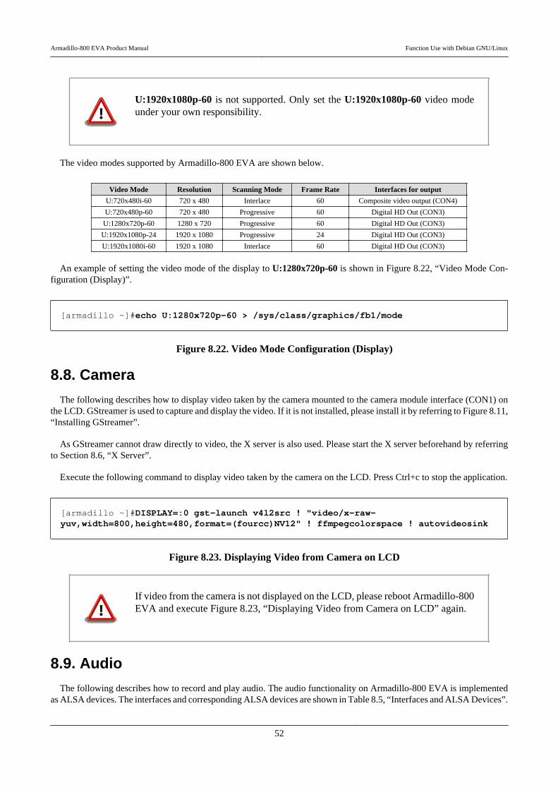
U:1920x1080p-60 is not supported. Only set the U:1920x1080p-60 video modeunder your own responsibility.
The video modes supported by Armadillo-800 EVA are shown below.
Video Mode Resolution Scanning Mode Frame Rate Interfaces for output
U:720x480i-60 720 x 480 Interlace 60 Composite video output (CON4)
U:720x480p-60 720 x 480 Progressive 60 Digital HD Out (CON3)
U:1280x720p-60 1280 x 720 Progressive 60 Digital HD Out (CON3)
U:1920x1080p-24 1920 x 1080 Progressive 24 Digital HD Out (CON3)
U:1920x1080i-60 1920 x 1080 Interlace 60 Digital HD Out (CON3)
An example of setting the video mode of the display to U:1280x720p-60 is shown in Figure 8.22, “Video Mode Con-figuration (Display)”.
[armadillo ~]#echo U:1280x720p-60 > /sys/class/graphics/fb1/mode
Figure 8.22. Video Mode Configuration (Display)
8.8. Camera
The following describes how to display video taken by the camera mounted to the camera module interface (CON1) onthe LCD. GStreamer is used to capture and display the video. If it is not installed, please install it by referring to Figure 8.11,“Installing GStreamer”.
As GStreamer cannot draw directly to video, the X server is also used. Please start the X server beforehand by referringto Section 8.6, “X Server”.
Execute the following command to display video taken by the camera on the LCD. Press Ctrl+c to stop the application.
[armadillo ~]#DISPLAY=:0 gst-launch v4l2src ! "video/x-raw- ⏎yuv,width=800,height=480,format=(fourcc)NV12" ! ffmpegcolorspace ! autovideosink
Figure 8.23. Displaying Video from Camera on LCD
If video from the camera is not displayed on the LCD, please reboot Armadillo-800EVA and execute Figure 8.23, “Displaying Video from Camera on LCD” again.
8.9. Audio
The following describes how to record and play audio. The audio functionality on Armadillo-800 EVA is implementedas ALSA devices. The interfaces and corresponding ALSA devices are shown in Table 8.5, “Interfaces and ALSA Devices”.
Armadillo-800 EVA Product Manual Function Use with Debian GNU/Linux
52
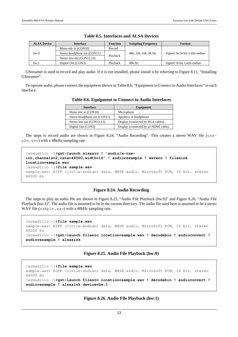
Table 8.5. Interfaces and ALSA Devices
ALSA Device Interface Function Sampling Frequency Format
hw:0
Mono mic in (CON10) Record
48k, 32k, 16k, 8k Hz Signed 16/24 bit, Little-endianStereo headphone out (CON11)Playback
Stereo line out (CON12,13)
hw:1 Digital Out (CON3) Playback 48k Hz Signed 16 bit, Little-endian
GStreamer is used to record and play audio. If it is not installed, please install it by referring to Figure 8.11, “InstallingGStreamer”.
To operate audio, please connect the equipment shown in Table 8.6, “Equipment to Connect to Audio Interfaces” to eachinterface.
Table 8.6. Equipment to Connect to Audio Interfaces
Interface Equipment
Mono mic in (CON10) Microphone
Stereo headphone out (CON11) Speakers or headphones
Stereo line out (CON12,13) Display (connected by RCA cables)
Digital Out (CON3) Display (connected by an HDMI cable)
The steps to record audio are shown in Figure 8.24, “Audio Recording”. This creates a stereo WAV file (sam-ple.wav) with a 48kHz sampling rate.
[armadillo ~]#gst-launch alsasrc ! 'audio/x-raw- ⏎int,channels=2,rate=48000,width=16' ! audioresample ! wavenc ! filesink ⏎location=sample.wav[armadillo ~]#file sample.wavsample.wav: RIFF (little-endian) data, WAVE audio, Microsoft PCM, 16 bit, stereo ⏎48000 Hz
Figure 8.24. Audio Recording
The steps to play an audio file are shown in Figure 8.25, “Audio File Playback (hw:0)” and Figure 8.26, “Audio FilePlayback (hw:1)”. The audio file is assumed to be in the current directory. The audio file used here is assumed to be a stereoWAV file (sample.wav) with a 48kHz sampling rate.
[armadillo ~]#file sample.wavsample.wav: RIFF (little-endian) data, WAVE audio, Microsoft PCM, 16 bit, stereo ⏎48000 Hz[armadillo ~]#gst-launch filesrc location=sample.wav ! decodebin ! audioconvert ! ⏎audioresample ! alsasink
Figure 8.25. Audio File Playback (hw:0)
[armadillo ~]#file sample.wavsample.wav: RIFF (little-endian) data, WAVE audio, Microsoft PCM, 16 bit, stereo ⏎48000 Hz[armadillo ~]#gst-launch filesrc location=sample.wav ! decodebin ! audioconvert ! ⏎audioresample ! alsasink device=hw:1
Figure 8.26. Audio File Playback (hw:1)
Armadillo-800 EVA Product Manual Function Use with Debian GNU/Linux
53
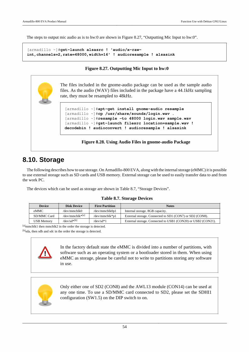
The steps to output mic audio as is to hw:0 are shown in Figure 8.27, “Outputting Mic Input to hw:0”.
[armadillo ~]#gst-launch alsasrc ! 'audio/x-raw- ⏎int,channels=2,rate=48000,width=16' ! audioresample ! alsasink
Figure 8.27. Outputting Mic Input to hw:0
The files included in the gnome-audio package can be used as the sample audiofiles. As the audio (WAV) files included in the package have a 44.1kHz samplingrate, they must be resampled to 48kHz.
[armadillo ~]#apt-get install gnome-audio resample[armadillo ~]#cp /usr/share/sounds/login.wav .[armadillo ~]#resample -to 48000 login.wav sample.wav[armadillo ~]#gst-launch filesrc location=sample.wav ! ⏎decodebin ! audioconvert ! audioresample ! alsasink
Figure 8.28. Using Audio Files in gnome-audio Package
8.10. StorageThe following describes how to use storage. On Armadillo-800 EVA, along with the internal storage (eMMC) it is possible
to use external storage such as SD cards and USB memory. External storage can be used to easily transfer data to and fromthe work PC.
The devices which can be used as storage are shown in Table 8.7, “Storage Devices”.
Table 8.7. Storage Devices
Device Disk Device First Partition Notes
eMMC /dev/mmcblk0 /dev/mmcblk0p1 Internal storage. 8GB capacity.
SD/MMC Card /dev/mmcblk*[a] /dev/mmcblk*p1 External storage. Connected to SD1 (CON7) or SD2 (CON8).
USB Memory /dev/sd*[b] /dev/sd*1 External storage. Connected to USB1 (CON20) or USB2 (CON21).[a]mmcblk1 then mmcblk2 in the order the storage is detected.[b]sda, then sdb and sdc in the order the storage is detected.
In the factory default state the eMMC is divided into a number of partitions, withsoftware such as an operating system or a bootloader stored in them. When usingeMMC as storage, please be careful not to write to partitions storing any softwarein use.
Only either one of SD2 (CON8) and the AWL13 module (CON14) can be used atany one time. To use a SD/MMC card connected to SD2, please set the SDHI1configuration (SW1.5) on the DIP switch to on.
Armadillo-800 EVA Product Manual Function Use with Debian GNU/Linux
54

Only either one of USB1 (CON20) and USB3 (CON24) can be used at any one time.To use USB memory connected to USB1, please set the USB0 configuration(SW1.6) on the DIP switch to off.
8.10.1. Using Storage
The following uses USB memory as an example to explain how to use storage.
In order to make storage usable, the storage file system must be mounted to the root file system. The mount commandis used for mounting. To mount a FAT32 file system in the first partition of USB memory to the /mnt/ directory in theroot file system, execute the following command.
[armadillo ~]#mount -t vfat /dev/sda1 /mnt
Figure 8.29. Mounting Storage
For mounting storage with other types of file systems and so on, please refer to themount man page for details.
[armadillo ~]# man 8 mount
The file systems supported by the Linux kernel can be displayed as shown below.
[armadillo ~]# cat /proc/filesystemsnodev sysfsnodev rootfs : : (abbreviated) :
To safely remove mounted storage it must be unmounted first. The umount command is used for unmounting. Tounmount storage mounted to the /mnt/ directory, execute the following command.
[armadillo ~]#umount /mnt
Figure 8.30. Unmounting Storage
8.10.2. Changing and Formatting Storage Partitions
The following uses an SD card as an example to explain how to change and format storage partitions.
Armadillo-800 EVA Product Manual Function Use with Debian GNU/Linux
55
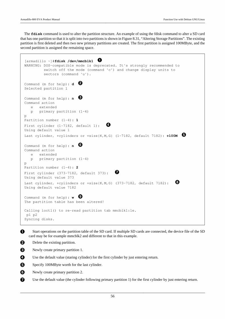
The fdisk command is used to alter the partition structure. An example of using the fdisk command to alter a SD cardthat has one partition so that it is split into two partitions is shown in Figure 8.31, “Altering Storage Partitions”. The existingpartition is first deleted and then two new primary partitions are created. The first partition is assigned 100MByte, and thesecond partition is assigned the remaining space.
[armadillo ~]#fdisk /dev/mmcblk1 WARNING: DOS-compatible mode is deprecated. It's strongly recommended to switch off the mode (command 'c') and change display units to sectors (command 'u').
Command (m for help): d Selected partition 1
Command (m for help): n Command action e extended p primary partition (1-4)pPartition number (1-4): 1
First cylinder (1-7182, default 1): Using default value 1
Last cylinder, +cylinders or +size{K,M,G} (1-7182, default 7182): +100M
Command (m for help): n Command action e extended p primary partition (1-4)pPartition number (1-4): 2
First cylinder (373-7182, default 373): Using default value 373
Last cylinder, +cylinders or +size{K,M,G} (373-7182, default 7182): Using default value 7182
Command (m for help): w The partition table has been altered!
Calling ioctl() to re-read partition tab mmcblk1:le. p1 p2Syncing disks.
Start operations on the partition table of the SD card. If multiple SD cards are connected, the device file of the SDcard may be for example mmcblk2 and different to that in this example.
Delete the existing partition.
Newly create primary partition 1.
Use the default value (staring cylinder) for the first cylinder by just entering return.
Specify 100MByte worth for the last cylinder.
Newly create primary partition 2.
Use the default value (the cylinder following primary partition 1) for the first cylinder by just entering return.
Armadillo-800 EVA Product Manual Function Use with Debian GNU/Linux
56
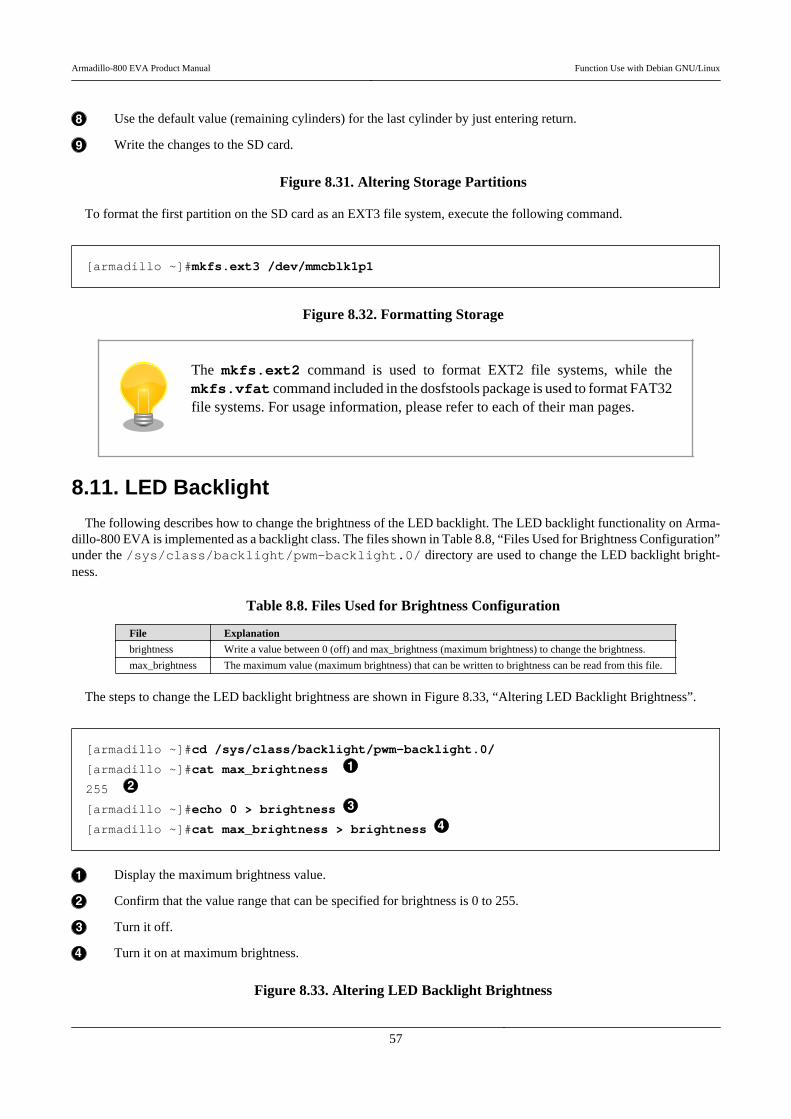
Use the default value (remaining cylinders) for the last cylinder by just entering return.
Write the changes to the SD card.
Figure 8.31. Altering Storage Partitions
To format the first partition on the SD card as an EXT3 file system, execute the following command.
[armadillo ~]#mkfs.ext3 /dev/mmcblk1p1
Figure 8.32. Formatting Storage
The mkfs.ext2 command is used to format EXT2 file systems, while themkfs.vfat command included in the dosfstools package is used to format FAT32file systems. For usage information, please refer to each of their man pages.
8.11. LED Backlight
The following describes how to change the brightness of the LED backlight. The LED backlight functionality on Arma-dillo-800 EVA is implemented as a backlight class. The files shown in Table 8.8, “Files Used for Brightness Configuration”under the /sys/class/backlight/pwm-backlight.0/ directory are used to change the LED backlight bright-ness.
Table 8.8. Files Used for Brightness Configuration
File Explanation
brightness Write a value between 0 (off) and max_brightness (maximum brightness) to change the brightness.
max_brightness The maximum value (maximum brightness) that can be written to brightness can be read from this file.
The steps to change the LED backlight brightness are shown in Figure 8.33, “Altering LED Backlight Brightness”.
[armadillo ~]#cd /sys/class/backlight/pwm-backlight.0/
[armadillo ~]#cat max_brightness
255
[armadillo ~]#echo 0 > brightness
[armadillo ~]#cat max_brightness > brightness
Display the maximum brightness value.
Confirm that the value range that can be specified for brightness is 0 to 255.
Turn it off.
Turn it on at maximum brightness.
Figure 8.33. Altering LED Backlight Brightness
Armadillo-800 EVA Product Manual Function Use with Debian GNU/Linux
57
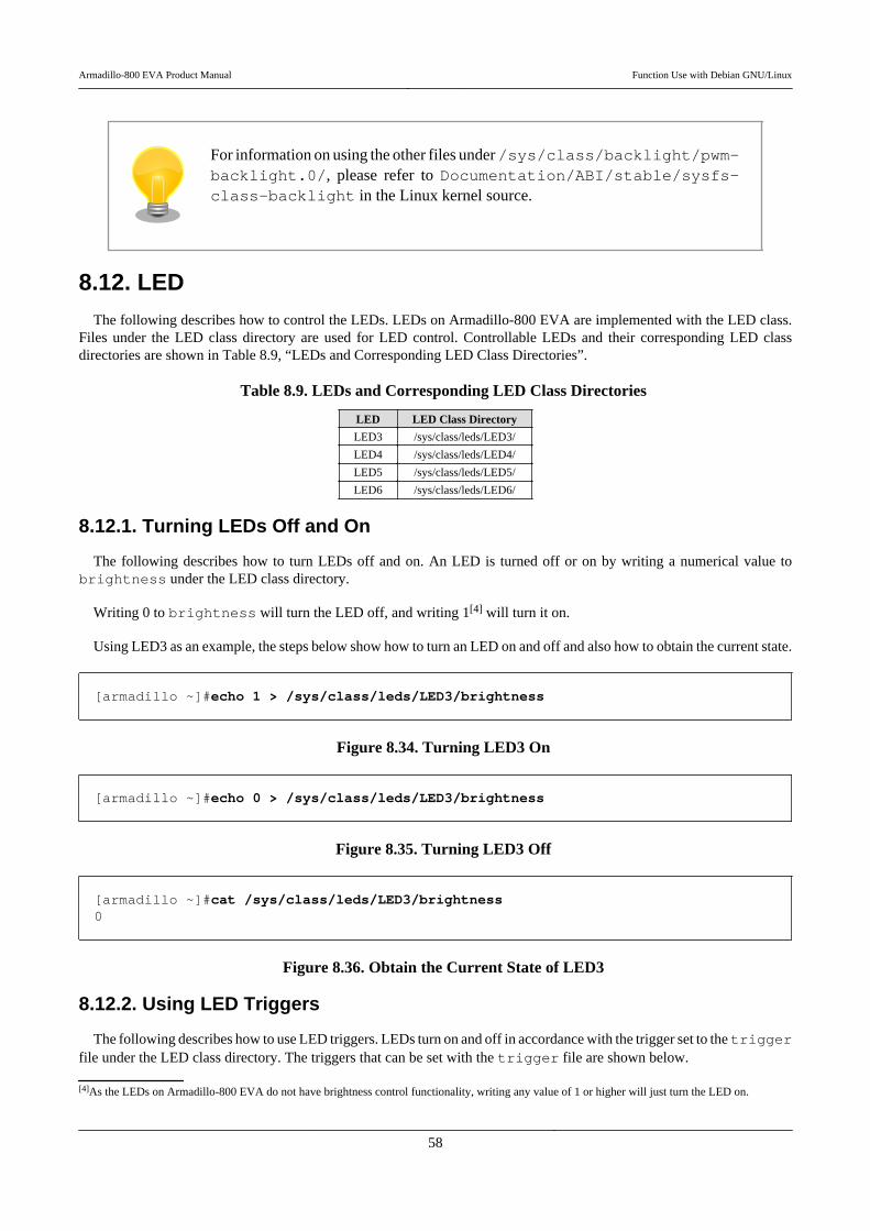
For information on using the other files under /sys/class/backlight/pwm-backlight.0/, please refer to Documentation/ABI/stable/sysfs-class-backlight in the Linux kernel source.
8.12. LEDThe following describes how to control the LEDs. LEDs on Armadillo-800 EVA are implemented with the LED class.
Files under the LED class directory are used for LED control. Controllable LEDs and their corresponding LED classdirectories are shown in Table 8.9, “LEDs and Corresponding LED Class Directories”.
Table 8.9. LEDs and Corresponding LED Class Directories
LED LED Class Directory
LED3 /sys/class/leds/LED3/
LED4 /sys/class/leds/LED4/
LED5 /sys/class/leds/LED5/
LED6 /sys/class/leds/LED6/
8.12.1. Turning LEDs Off and On
The following describes how to turn LEDs off and on. An LED is turned off or on by writing a numerical value tobrightness under the LED class directory.
Writing 0 to brightness will turn the LED off, and writing 1[4] will turn it on.
Using LED3 as an example, the steps below show how to turn an LED on and off and also how to obtain the current state.
[armadillo ~]#echo 1 > /sys/class/leds/LED3/brightness
Figure 8.34. Turning LED3 On
[armadillo ~]#echo 0 > /sys/class/leds/LED3/brightness
Figure 8.35. Turning LED3 Off
[armadillo ~]#cat /sys/class/leds/LED3/brightness0
Figure 8.36. Obtain the Current State of LED3
8.12.2. Using LED Triggers
The following describes how to use LED triggers. LEDs turn on and off in accordance with the trigger set to the triggerfile under the LED class directory. The triggers that can be set with the trigger file are shown below.
[4]As the LEDs on Armadillo-800 EVA do not have brightness control functionality, writing any value of 1 or higher will just turn the LED on.
Armadillo-800 EVA Product Manual Function Use with Debian GNU/Linux
58

Table 8.10. Triggers Configurable with the trigger File
Trigger Explanation
none No trigger set (default).
battery-charging-or-full This is a dummy trigger. It is always off.
battery-charging This is a dummy trigger. It is always off.
battery-full This is a dummy trigger. It is always off.
usb-online This is a dummy trigger. It is always off.
ac-online This is a dummy trigger. It is always off.
mmc0 Acts as eMMC access lamp.
mmc1 Acts as SD1 access lamp.
mmc2 Acts as SD2 or AWL13 module access lamp.
timerTurns on and off at specified timing. When this is selected the delay_on and delay_off files appear under theLED class directory. The on time in milliseconds is specified to the former and off time to the later.
Using LED3 as an example, the steps below show how to configure a trigger and to also obtain the current configuration.
[armadillo ~]#echo timer > /sys/class/leds/LED3/trigger[armadillo ~]#echo 1000 > /sys/class/leds/LED3/delay_on[armadillo ~]#echo 500 > /sys/class/leds/LED3/delay_off
Figure 8.37. Setting LED3 Trigger to timer
[armadillo ~]#cat /sys/class/leds/LED3/triggernone battery-charging-or-full battery-charging battery-full usb-online ac-online ⏎mmc0 mmc1 mmc2 [timer]
Figure 8.38. Displaying LED3 Trigger
8.13. User SwitchThe following describes how to obtain events from user switches. User switches on Armadillo-800 EVA are implemented
as input devices. The switches that can be used as user switches, and their corresponding input device files are shown inTable 8.11, “Switches and Corresponding Input Device Files”.
Table 8.11. Switches and Corresponding Input Device Files
User Switch Input Device File Event Code
SW3
/dev/input/event0
116 (Power)
SW4 158 (Back)
SW5 139 (Menu)
SW6 102 (Home)
SW3 was assigned as 28 (Enter) on linux-2.6.35-a800eva-at1. This was changed to116 (Power) on linux-2.6.35-a800eva-at2 and later.
SW2 is a reset switch. It cannot be used as a user switch. Please take care as theArmadillo-800 EVA will be reset when it is pressed.
Armadillo-800 EVA Product Manual Function Use with Debian GNU/Linux
59
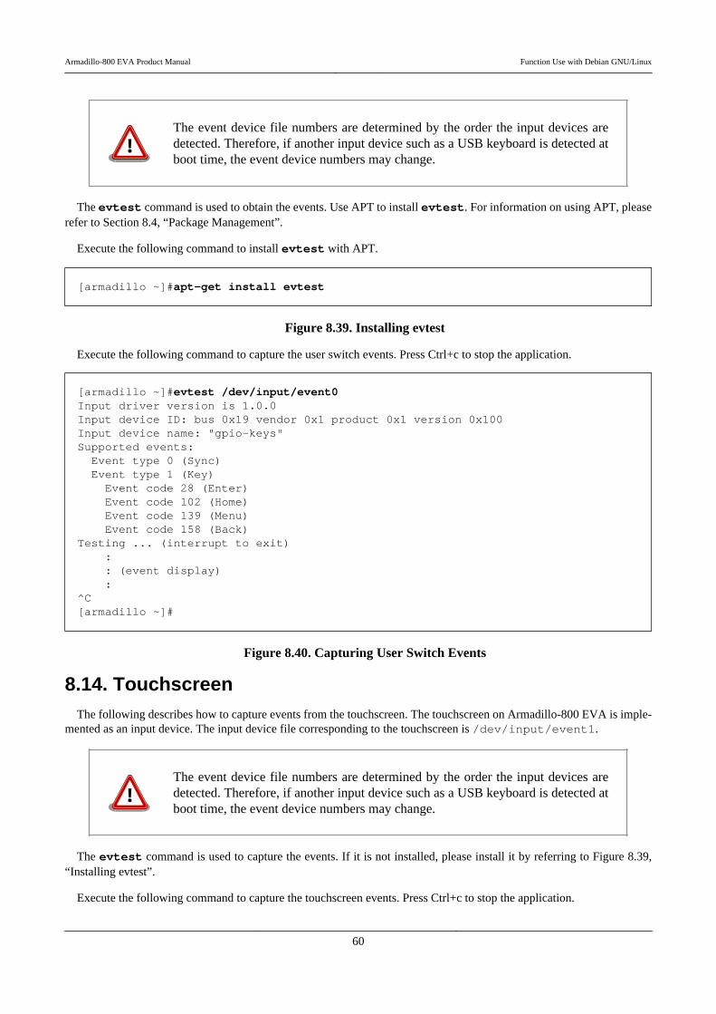
The event device file numbers are determined by the order the input devices aredetected. Therefore, if another input device such as a USB keyboard is detected atboot time, the event device numbers may change.
The evtest command is used to obtain the events. Use APT to install evtest. For information on using APT, pleaserefer to Section 8.4, “Package Management”.
Execute the following command to install evtest with APT.
[armadillo ~]#apt-get install evtest
Figure 8.39. Installing evtest
Execute the following command to capture the user switch events. Press Ctrl+c to stop the application.
[armadillo ~]#evtest /dev/input/event0Input driver version is 1.0.0Input device ID: bus 0x19 vendor 0x1 product 0x1 version 0x100Input device name: "gpio-keys"Supported events: Event type 0 (Sync) Event type 1 (Key) Event code 28 (Enter) Event code 102 (Home) Event code 139 (Menu) Event code 158 (Back)Testing ... (interrupt to exit) : : (event display) :^C[armadillo ~]#
Figure 8.40. Capturing User Switch Events
8.14. TouchscreenThe following describes how to capture events from the touchscreen. The touchscreen on Armadillo-800 EVA is imple-
mented as an input device. The input device file corresponding to the touchscreen is /dev/input/event1.
The event device file numbers are determined by the order the input devices aredetected. Therefore, if another input device such as a USB keyboard is detected atboot time, the event device numbers may change.
The evtest command is used to capture the events. If it is not installed, please install it by referring to Figure 8.39,“Installing evtest”.
Execute the following command to capture the touchscreen events. Press Ctrl+c to stop the application.
Armadillo-800 EVA Product Manual Function Use with Debian GNU/Linux
60
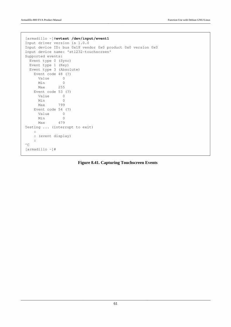
[armadillo ~]#evtest /dev/input/event1Input driver version is 1.0.0Input device ID: bus 0x18 vendor 0x0 product 0x0 version 0x0Input device name: "st1232-touchscreen"Supported events: Event type 0 (Sync) Event type 1 (Key) Event type 3 (Absolute) Event code 48 (?) Value 0 Min 0 Max 255 Event code 53 (?) Value 0 Min 0 Max 799 Event code 54 (?) Value 0 Min 0 Max 479Testing ... (interrupt to exit) : : (event display) :^C[armadillo ~]#
Figure 8.41. Capturing Touchscreen Events
Armadillo-800 EVA Product Manual Function Use with Debian GNU/Linux
61
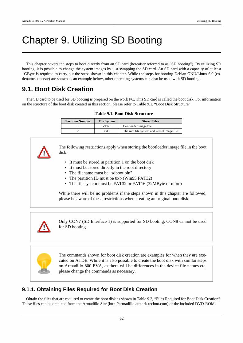
Chapter 9. Utilizing SD Booting
This chapter covers the steps to boot directly from an SD card (hereafter referred to as "SD booting"). By utilizing SDbooting, it is possible to change the system images by just swapping the SD card. An SD card with a capacity of at least1GByte is required to carry out the steps shown in this chapter. While the steps for booting Debian GNU/Linux 6.0 (co-dename squeeze) are shown as an example below, other operating systems can also be used with SD booting.
9.1. Boot Disk CreationThe SD card to be used for SD booting is prepared on the work PC. This SD card is called the boot disk. For information
on the structure of the boot disk created in this section, please refer to Table 9.1, “Boot Disk Structure”.
Table 9.1. Boot Disk Structure
Partition Number File System Stored Files
1 VFAT Bootloader image file
2 ext3 The root file system and kernel image file
The following restrictions apply when storing the bootloader image file in the bootdisk.
• It must be stored in partition 1 on the boot disk• It must be stored directly in the root directory• The filename must be "sdboot.bin"• The partition ID must be 0xb (Win95 FAT32)• The file system must be FAT32 or FAT16 (32MByte or more)
While there will be no problems if the steps shown in this chapter are followed,please be aware of these restrictions when creating an original boot disk.
Only CON7 (SD Interface 1) is supported for SD booting. CON8 cannot be usedfor SD booting.
The commands shown for boot disk creation are examples for when they are exe-cuted on ATDE. While it is also possible to create the boot disk with similar stepson Armadillo-800 EVA, as there will be differences in the device file names etc,please change the commands as necessary.
9.1.1. Obtaining Files Required for Boot Disk Creation
Obtain the files that are required to create the boot disk as shown in Table 9.2, “Files Required for Boot Disk Creation”.These files can be obtained from the Armadillo Site (http://armadillo.atmark-techno.com) or the included DVD-ROM.
Armadillo-800 EVA Product Manual Utilizing SD Booting
62
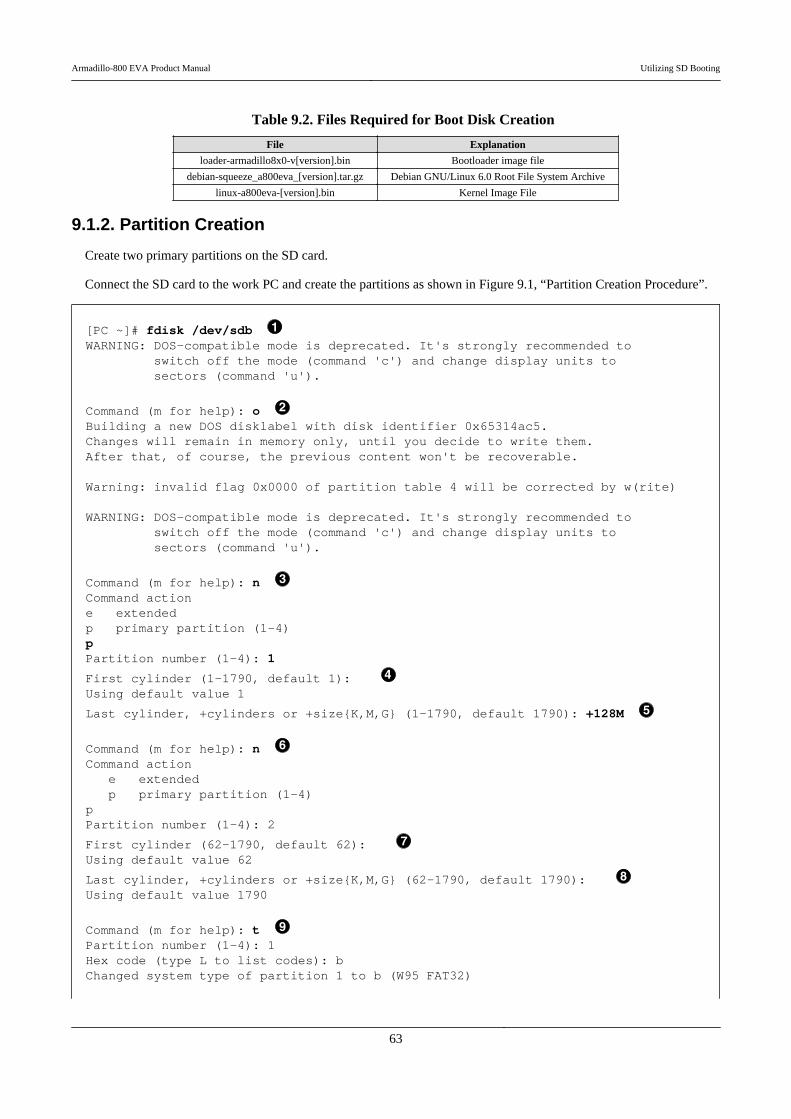
Table 9.2. Files Required for Boot Disk Creation
File Explanation
loader-armadillo8x0-v[version].bin Bootloader image file
debian-squeeze_a800eva_[version].tar.gz Debian GNU/Linux 6.0 Root File System Archive
linux-a800eva-[version].bin Kernel Image File
9.1.2. Partition Creation
Create two primary partitions on the SD card.
Connect the SD card to the work PC and create the partitions as shown in Figure 9.1, “Partition Creation Procedure”.
[PC ~]# fdisk /dev/sdb WARNING: DOS-compatible mode is deprecated. It's strongly recommended to switch off the mode (command 'c') and change display units to sectors (command 'u').
Command (m for help): o Building a new DOS disklabel with disk identifier 0x65314ac5.Changes will remain in memory only, until you decide to write them.After that, of course, the previous content won't be recoverable.
Warning: invalid flag 0x0000 of partition table 4 will be corrected by w(rite)
WARNING: DOS-compatible mode is deprecated. It's strongly recommended to switch off the mode (command 'c') and change display units to sectors (command 'u').
Command (m for help): n Command actione extendedp primary partition (1-4)pPartition number (1-4): 1
First cylinder (1-1790, default 1): Using default value 1
Last cylinder, +cylinders or +size{K,M,G} (1-1790, default 1790): +128M
Command (m for help): n Command action e extended p primary partition (1-4)pPartition number (1-4): 2
First cylinder (62-1790, default 62): Using default value 62
Last cylinder, +cylinders or +size{K,M,G} (62-1790, default 1790): Using default value 1790
Command (m for help): t Partition number (1-4): 1Hex code (type L to list codes): bChanged system type of partition 1 to b (W95 FAT32)
Armadillo-800 EVA Product Manual Utilizing SD Booting
63
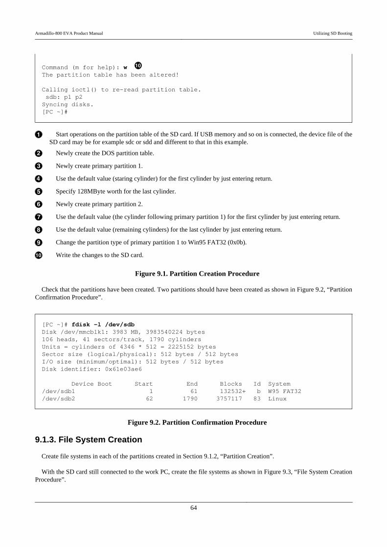
Command (m for help): w The partition table has been altered!
Calling ioctl() to re-read partition table. sdb: p1 p2Syncing disks.[PC ~]#
Start operations on the partition table of the SD card. If USB memory and so on is connected, the device file of theSD card may be for example sdc or sdd and different to that in this example.
Newly create the DOS partition table.
Newly create primary partition 1.
Use the default value (staring cylinder) for the first cylinder by just entering return.
Specify 128MByte worth for the last cylinder.
Newly create primary partition 2.
Use the default value (the cylinder following primary partition 1) for the first cylinder by just entering return.
Use the default value (remaining cylinders) for the last cylinder by just entering return.
Change the partition type of primary partition 1 to Win95 FAT32 (0x0b).
Write the changes to the SD card.
Figure 9.1. Partition Creation Procedure
Check that the partitions have been created. Two partitions should have been created as shown in Figure 9.2, “PartitionConfirmation Procedure”.
[PC ~]# fdisk -l /dev/sdbDisk /dev/mmcblk1: 3983 MB, 3983540224 bytes106 heads, 41 sectors/track, 1790 cylindersUnits = cylinders of 4346 * 512 = 2225152 bytesSector size (logical/physical): 512 bytes / 512 bytesI/O size (minimum/optimal): 512 bytes / 512 bytesDisk identifier: 0x61e03ae6
Device Boot Start End Blocks Id System/dev/sdb1 1 61 132532+ b W95 FAT32/dev/sdb2 62 1790 3757117 83 Linux
Figure 9.2. Partition Confirmation Procedure
9.1.3. File System Creation
Create file systems in each of the partitions created in Section 9.1.2, “Partition Creation”.
With the SD card still connected to the work PC, create the file systems as shown in Figure 9.3, “File System CreationProcedure”.
Armadillo-800 EVA Product Manual Utilizing SD Booting
64

The mkfs.vfat command (dosfstools package) is used for the file system creation.If it is not installed on the work PC, please install it as shown below.
[PC ~]# apt-get update[PC ~]# apt-get install dosfstools
[PC ~]# mkfs.vfat /dev/sdb1 mkfs.vfat 3.0.9 (31 Jan 2010)
[PC ~]# mkfs.ext3 /dev/sdb2 mke2fs 1.41.12 (17-May-2010)Filesystem label=OS type: LinuxBlock size=4096 (log=2)Fragment size=4096 (log=2)Stride=0 blocks, Stripe width=0 blocks235248 inodes, 939279 blocks46963 blocks (5.00%) reserved for the super userFirst data block=0Maximum filesystem blocks=96468992029 block groups32768 blocks per group, 32768 fragments per group8112 inodes per groupSuperblock backups stored on blocks: 32768, 98304, 163840, 229376, 294912, 819200, 884736
Writing inode tables: doneCreating journal (16384 blocks): doneWriting superblocks and filesystem accounting information: done
This filesystem will be automatically checked every 21 mounts or180 days, whichever comes first. Use tune2fs -c or -i to override.[PC ~]#
Create a VFAT file system in primary partition 1.
Create an ext3 file system in primary partition 2.
Figure 9.3. File System Creation Procedure
9.1.4. System Image Extraction
Extract the files obtained in Section 9.1.1, “Obtaining Files Required for Boot Disk Creation” to the SD card with thefile systems created in Section 9.1.3, “File System Creation”.
With the SD card still connected to the work PC, extract the files as shown in Figure 9.4, “System Image ExtractionProcedure”. In the command examples below, it is assumed that the files obtained in Section 9.1.1, “Obtaining Files Requiredfor Boot Disk Creation” are in the current directory.
[PC ~]# lsdebian-squeeze_a800eva_[version].tar.gz loader-armadillo8x0-v[version].bin
Armadillo-800 EVA Product Manual Utilizing SD Booting
65
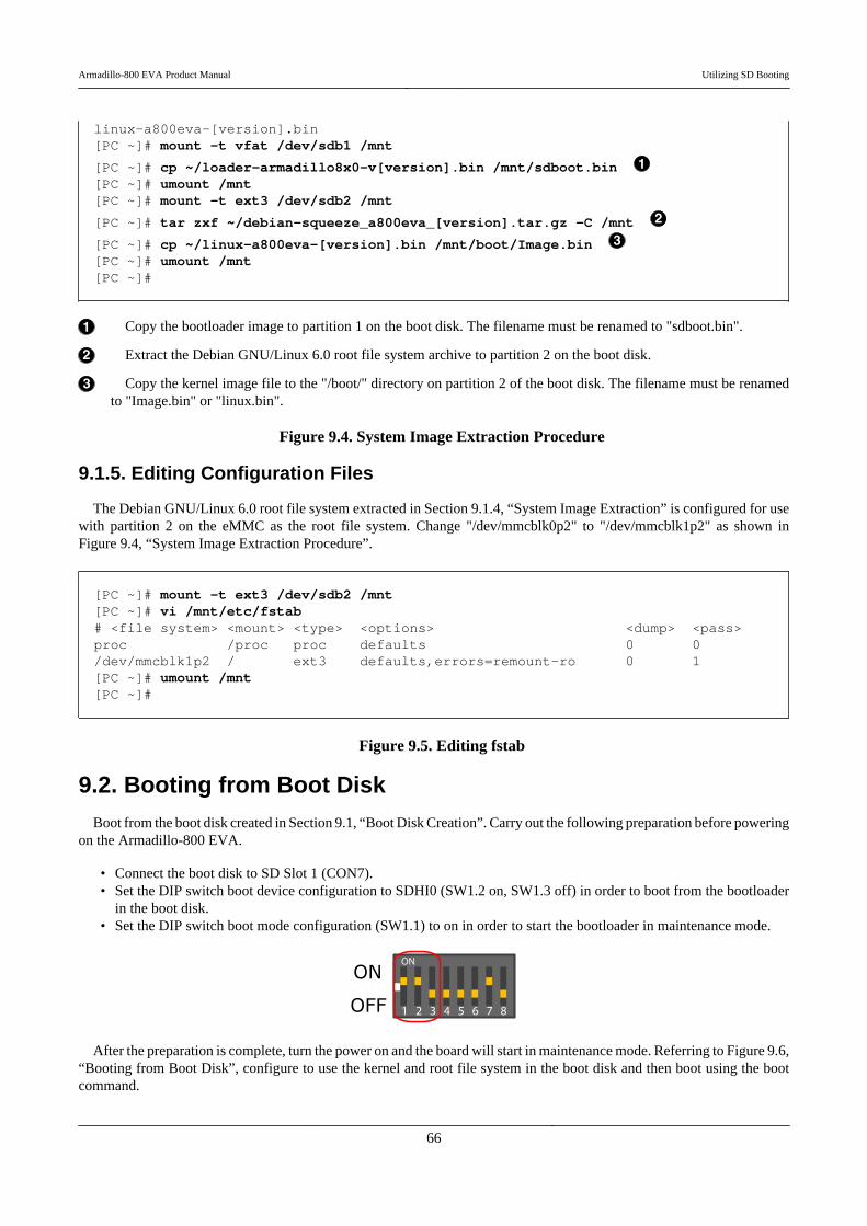
linux-a800eva-[version].bin[PC ~]# mount -t vfat /dev/sdb1 /mnt
[PC ~]# cp ~/loader-armadillo8x0-v[version].bin /mnt/sdboot.bin [PC ~]# umount /mnt[PC ~]# mount -t ext3 /dev/sdb2 /mnt
[PC ~]# tar zxf ~/debian-squeeze_a800eva_[version].tar.gz -C /mnt
[PC ~]# cp ~/linux-a800eva-[version].bin /mnt/boot/Image.bin [PC ~]# umount /mnt[PC ~]#
Copy the bootloader image to partition 1 on the boot disk. The filename must be renamed to "sdboot.bin".
Extract the Debian GNU/Linux 6.0 root file system archive to partition 2 on the boot disk.
Copy the kernel image file to the "/boot/" directory on partition 2 of the boot disk. The filename must be renamedto "Image.bin" or "linux.bin".
Figure 9.4. System Image Extraction Procedure
9.1.5. Editing Configuration Files
The Debian GNU/Linux 6.0 root file system extracted in Section 9.1.4, “System Image Extraction” is configured for usewith partition 2 on the eMMC as the root file system. Change "/dev/mmcblk0p2" to "/dev/mmcblk1p2" as shown inFigure 9.4, “System Image Extraction Procedure”.
[PC ~]# mount -t ext3 /dev/sdb2 /mnt[PC ~]# vi /mnt/etc/fstab# <file system> <mount> <type> <options> <dump> <pass>proc /proc proc defaults 0 0/dev/mmcblk1p2 / ext3 defaults,errors=remount-ro 0 1[PC ~]# umount /mnt[PC ~]#
Figure 9.5. Editing fstab
9.2. Booting from Boot DiskBoot from the boot disk created in Section 9.1, “Boot Disk Creation”. Carry out the following preparation before powering
on the Armadillo-800 EVA.
• Connect the boot disk to SD Slot 1 (CON7).• Set the DIP switch boot device configuration to SDHI0 (SW1.2 on, SW1.3 off) in order to boot from the bootloader
in the boot disk.• Set the DIP switch boot mode configuration (SW1.1) to on in order to start the bootloader in maintenance mode.
After the preparation is complete, turn the power on and the board will start in maintenance mode. Referring to Figure 9.6,“Booting from Boot Disk”, configure to use the kernel and root file system in the boot disk and then boot using the bootcommand.
Armadillo-800 EVA Product Manual Utilizing SD Booting
66

hermit> setbootdevice mmcblk1p2hermit> setenv console=ttySC1,115200 noinitrd rootwait root=/dev/mmcblk1p2hermit> boot
Figure 9.6. Booting from Boot Disk
Armadillo-800 EVA Product Manual Utilizing SD Booting
67
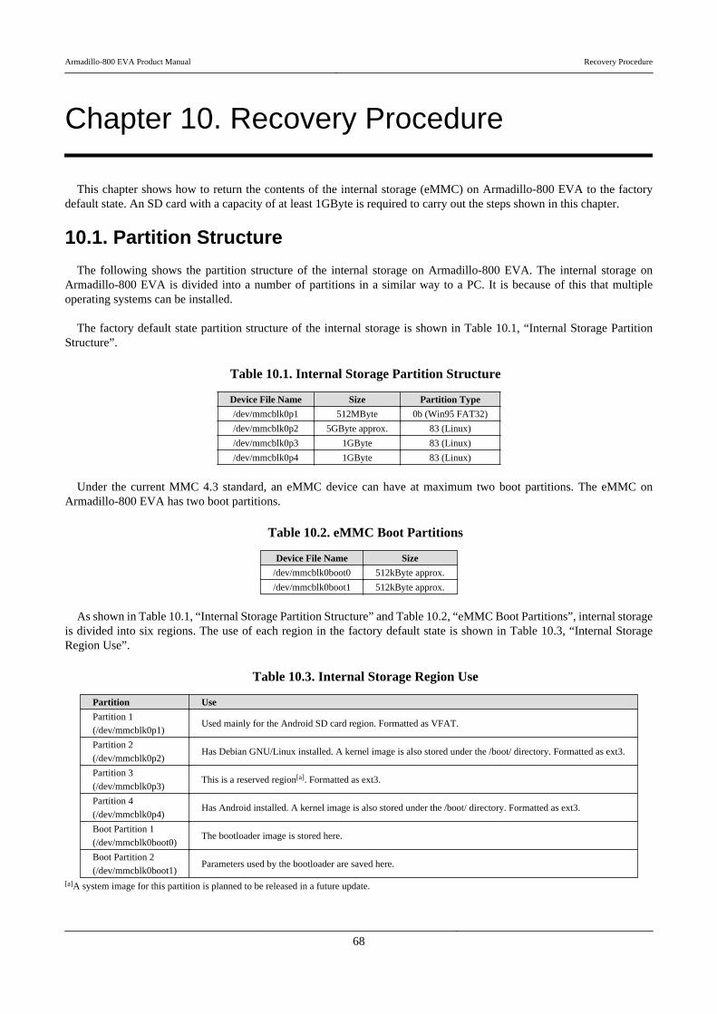
Chapter 10. Recovery Procedure
This chapter shows how to return the contents of the internal storage (eMMC) on Armadillo-800 EVA to the factorydefault state. An SD card with a capacity of at least 1GByte is required to carry out the steps shown in this chapter.
10.1. Partition Structure
The following shows the partition structure of the internal storage on Armadillo-800 EVA. The internal storage onArmadillo-800 EVA is divided into a number of partitions in a similar way to a PC. It is because of this that multipleoperating systems can be installed.
The factory default state partition structure of the internal storage is shown in Table 10.1, “Internal Storage PartitionStructure”.
Table 10.1. Internal Storage Partition Structure
Device File Name Size Partition Type
/dev/mmcblk0p1 512MByte 0b (Win95 FAT32)
/dev/mmcblk0p2 5GByte approx. 83 (Linux)
/dev/mmcblk0p3 1GByte 83 (Linux)
/dev/mmcblk0p4 1GByte 83 (Linux)
Under the current MMC 4.3 standard, an eMMC device can have at maximum two boot partitions. The eMMC onArmadillo-800 EVA has two boot partitions.
Table 10.2. eMMC Boot Partitions
Device File Name Size
/dev/mmcblk0boot0 512kByte approx.
/dev/mmcblk0boot1 512kByte approx.
As shown in Table 10.1, “Internal Storage Partition Structure” and Table 10.2, “eMMC Boot Partitions”, internal storageis divided into six regions. The use of each region in the factory default state is shown in Table 10.3, “Internal StorageRegion Use”.
Table 10.3. Internal Storage Region Use
Partition Use
Partition 1
(/dev/mmcblk0p1)Used mainly for the Android SD card region. Formatted as VFAT.
Partition 2
(/dev/mmcblk0p2)Has Debian GNU/Linux installed. A kernel image is also stored under the /boot/ directory. Formatted as ext3.
Partition 3
(/dev/mmcblk0p3)This is a reserved region[a]. Formatted as ext3.
Partition 4
(/dev/mmcblk0p4)Has Android installed. A kernel image is also stored under the /boot/ directory. Formatted as ext3.
Boot Partition 1
(/dev/mmcblk0boot0)The bootloader image is stored here.
Boot Partition 2
(/dev/mmcblk0boot1)Parameters used by the bootloader are saved here.
[a]A system image for this partition is planned to be released in a future update.
Armadillo-800 EVA Product Manual Recovery Procedure
68
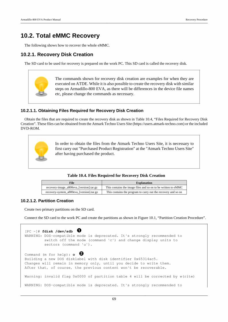
10.2. Total eMMC RecoveryThe following shows how to recover the whole eMMC.
10.2.1. Recovery Disk Creation
The SD card to be used for recovery is prepared on the work PC. This SD card is called the recovery disk.
The commands shown for recovery disk creation are examples for when they areexecuted on ATDE. While it is also possible to create the recovery disk with similarsteps on Armadillo-800 EVA, as there will be differences in the device file namesetc, please change the commands as necessary.
10.2.1.1. Obtaining Files Required for Recovery Disk Creation
Obtain the files that are required to create the recovery disk as shown in Table 10.4, “Files Required for Recovery DiskCreation”. These files can be obtained from the Atmark Techno Users Site (https://users.atmark-techno.com) or the includedDVD-ROM.
In order to obtain the files from the Atmark Techno Users Site, it is necessary tofirst carry out "Purchased Product Registration" at the "Atmark Techno Users Site"after having purchased the product.
Table 10.4. Files Required for Recovery Disk Creation
File Explanation
recovery-image_a800eva_[version].tar.gz This contains the image files and so on to be written to eMMC
recovery-system_a800eva_[version].tar.gz This contains the program to carry out the recovery and so on
10.2.1.2. Partition Creation
Create two primary partitions on the SD card.
Connect the SD card to the work PC and create the partitions as shown in Figure 10.1, “Partition Creation Procedure”.
[PC ~]# fdisk /dev/sdb WARNING: DOS-compatible mode is deprecated. It's strongly recommended to switch off the mode (command 'c') and change display units to sectors (command 'u').
Command (m for help): o Building a new DOS disklabel with disk identifier 0x65314ac5.Changes will remain in memory only, until you decide to write them.After that, of course, the previous content won't be recoverable.
Warning: invalid flag 0x0000 of partition table 4 will be corrected by w(rite)
WARNING: DOS-compatible mode is deprecated. It's strongly recommended to
Armadillo-800 EVA Product Manual Recovery Procedure
69
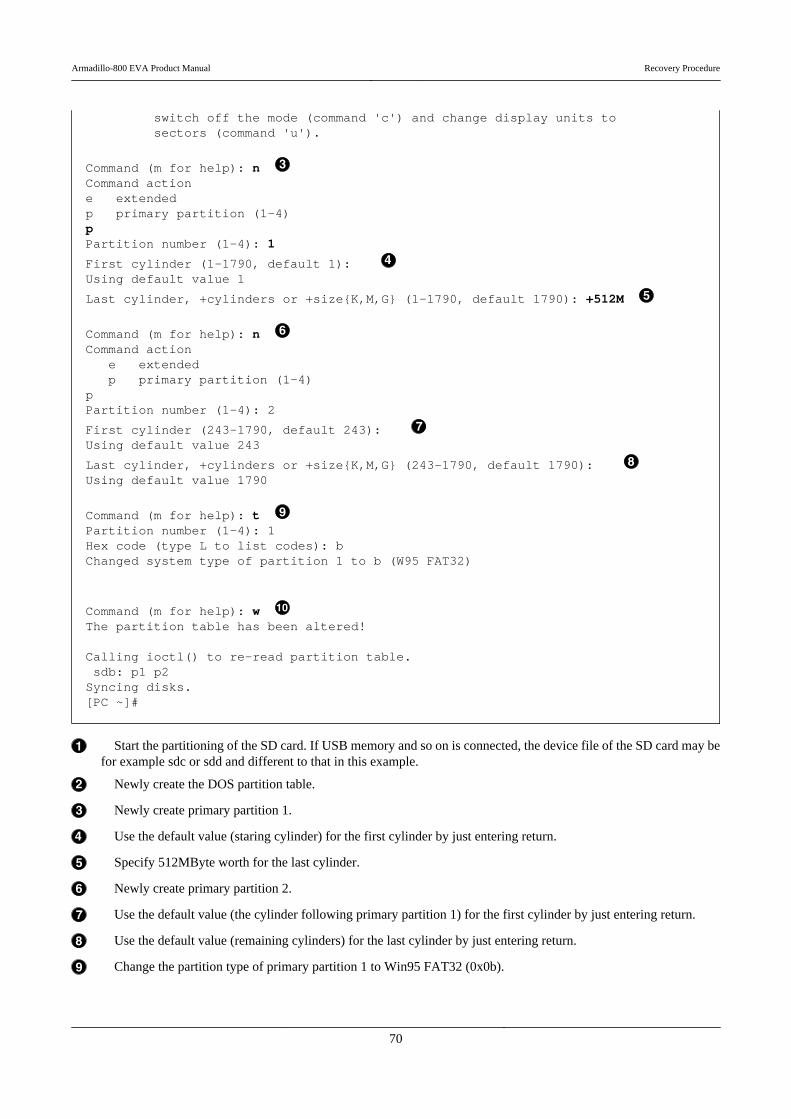
switch off the mode (command 'c') and change display units to sectors (command 'u').
Command (m for help): n Command actione extendedp primary partition (1-4)pPartition number (1-4): 1
First cylinder (1-1790, default 1): Using default value 1
Last cylinder, +cylinders or +size{K,M,G} (1-1790, default 1790): +512M
Command (m for help): n Command action e extended p primary partition (1-4)pPartition number (1-4): 2
First cylinder (243-1790, default 243): Using default value 243
Last cylinder, +cylinders or +size{K,M,G} (243-1790, default 1790): Using default value 1790
Command (m for help): t Partition number (1-4): 1Hex code (type L to list codes): bChanged system type of partition 1 to b (W95 FAT32)
Command (m for help): w The partition table has been altered!
Calling ioctl() to re-read partition table. sdb: p1 p2Syncing disks.[PC ~]#
Start the partitioning of the SD card. If USB memory and so on is connected, the device file of the SD card may befor example sdc or sdd and different to that in this example.
Newly create the DOS partition table.
Newly create primary partition 1.
Use the default value (staring cylinder) for the first cylinder by just entering return.
Specify 512MByte worth for the last cylinder.
Newly create primary partition 2.
Use the default value (the cylinder following primary partition 1) for the first cylinder by just entering return.
Use the default value (remaining cylinders) for the last cylinder by just entering return.
Change the partition type of primary partition 1 to Win95 FAT32 (0x0b).
Armadillo-800 EVA Product Manual Recovery Procedure
70
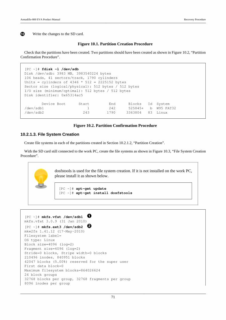
Write the changes to the SD card.
Figure 10.1. Partition Creation Procedure
Check that the partitions have been created. Two partitions should have been created as shown in Figure 10.2, “PartitionConfirmation Procedure”.
[PC ~]# fdisk -l /dev/sdbDisk /dev/sdb: 3983 MB, 3983540224 bytes106 heads, 41 sectors/track, 1790 cylindersUnits = cylinders of 4346 * 512 = 2225152 bytesSector size (logical/physical): 512 bytes / 512 bytesI/O size (minimum/optimal): 512 bytes / 512 bytesDisk identifier: 0x65314ac5
Device Boot Start End Blocks Id System/dev/sdb1 1 242 525845+ b W95 FAT32/dev/sdb2 243 1790 3363804 83 Linux
Figure 10.2. Partition Confirmation Procedure
10.2.1.3. File System Creation
Create file systems in each of the partitions created in Section 10.2.1.2, “Partition Creation”.
With the SD card still connected to the work PC, create the file systems as shown in Figure 10.3, “File System CreationProcedure”.
dosfstools is used for the file system creation. If it is not installed on the work PC,please install it as shown below.
[PC ~]# apt-get update[PC ~]# apt-get install dosfstools
[PC ~]# mkfs.vfat /dev/sdb1 mkfs.vfat 3.0.9 (31 Jan 2010)
[PC ~]# mkfs.ext3 /dev/sdb2 mke2fs 1.41.12 (17-May-2010)Filesystem label=OS type: LinuxBlock size=4096 (log=2)Fragment size=4096 (log=2)Stride=0 blocks, Stripe width=0 blocks210496 inodes, 840951 blocks42047 blocks (5.00%) reserved for the super userFirst data block=0Maximum filesystem blocks=86402662426 block groups32768 blocks per group, 32768 fragments per group8096 inodes per group
Armadillo-800 EVA Product Manual Recovery Procedure
71
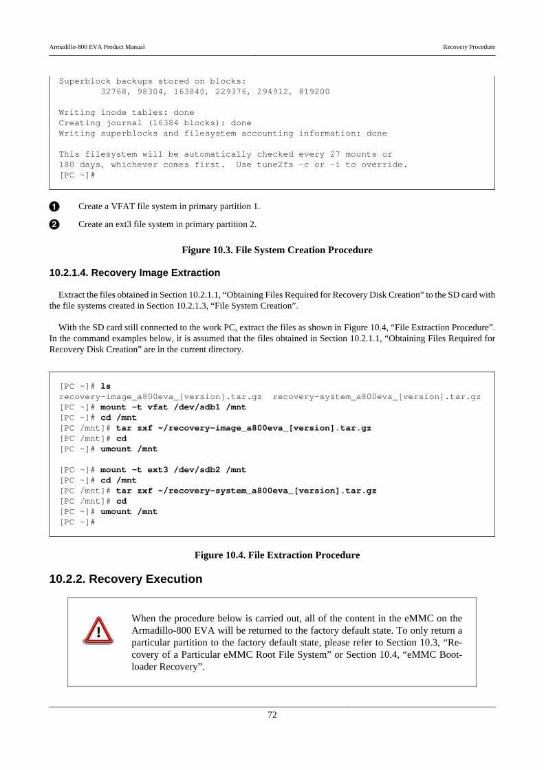
Superblock backups stored on blocks: 32768, 98304, 163840, 229376, 294912, 819200
Writing inode tables: doneCreating journal (16384 blocks): doneWriting superblocks and filesystem accounting information: done
This filesystem will be automatically checked every 27 mounts or180 days, whichever comes first. Use tune2fs -c or -i to override.[PC ~]#
Create a VFAT file system in primary partition 1.
Create an ext3 file system in primary partition 2.
Figure 10.3. File System Creation Procedure
10.2.1.4. Recovery Image Extraction
Extract the files obtained in Section 10.2.1.1, “Obtaining Files Required for Recovery Disk Creation” to the SD card withthe file systems created in Section 10.2.1.3, “File System Creation”.
With the SD card still connected to the work PC, extract the files as shown in Figure 10.4, “File Extraction Procedure”.In the command examples below, it is assumed that the files obtained in Section 10.2.1.1, “Obtaining Files Required forRecovery Disk Creation” are in the current directory.
[PC ~]# lsrecovery-image_a800eva_[version].tar.gz recovery-system_a800eva_[version].tar.gz[PC ~]# mount -t vfat /dev/sdb1 /mnt[PC ~]# cd /mnt[PC /mnt]# tar zxf ~/recovery-image_a800eva_[version].tar.gz[PC /mnt]# cd[PC ~]# umount /mnt
[PC ~]# mount -t ext3 /dev/sdb2 /mnt[PC ~]# cd /mnt[PC /mnt]# tar zxf ~/recovery-system_a800eva_[version].tar.gz[PC /mnt]# cd[PC ~]# umount /mnt[PC ~]#
Figure 10.4. File Extraction Procedure
10.2.2. Recovery Execution
When the procedure below is carried out, all of the content in the eMMC on theArmadillo-800 EVA will be returned to the factory default state. To only return aparticular partition to the factory default state, please refer to Section 10.3, “Re-covery of a Particular eMMC Root File System” or Section 10.4, “eMMC Boot-loader Recovery”.
Armadillo-800 EVA Product Manual Recovery Procedure
72

Use the recovery disk created in Section 10.2.1, “Recovery Disk Creation” to perform the recovery. Carry out the prep-aration below before powering on the Armadillo-800 EVA.
• On the DIP switch turn SW1.2 and SW1.7 on and all others off.
• Connect the recovery disk to SD Slot 1 (CON7).
After the preparation is complete, power on the board while pressing SW3 and the recovery will start. The recoveryprogress can be seen with the LED patterns.
Table 10.5. Recover Progress and LEDs
LED3 LED4 LED5 LED6 Recovery Progress
Blinking Off Off Off Formatting eMMC user partitions
Off Blinking Off Off Formatting eMMC boot partitions
Blinking On On On Creating system in eMMC partition 1
On Blinking On On Creating system in eMMC partition 2
On On Blinking On Creating system in eMMC partition 3
On On On Blinking Creating system in eMMC partition 4
On On On On Recovery completed successfully
Blinking Blinking Blinking Blinking Recovery ended abnormally
The recovery is complete when all the LEDs are on. If all LEDs are blinking an error has occurred. In this case, pleasecheck the steps and execute the recovery again. To boot from eMMC after recovery, set the DIP switch boot device con-figuration to eMMC (SW1.2 off, SW1.3 off), remove the SD card and power on the board.
10.3. Recovery of a Particular eMMC Root File System
The following introduces how to recover just a particular eMMC root file system. The candidates for recovery are asshown in Table 10.6, “Candidate Root File Systems for Recovery”.
Table 10.6. Candidate Root File Systems for Recovery
Root File System Partition Number File System
Debian GNU/Linux 2 ext3
Android 4 ext3
The Armadillo-800 EVA must be booted from SD beforehand by referring to Chapter 9, Utilizing SD Booting.
10.3.1. Debian GNU/Linux Recovery
The following shows how to recover Debian GNU/Linux to eMMC partition 2.
10.3.1.1. Obtaining Files Required for Debian GNU/Linux Recovery
Obtain the files that are required in order to recover Debian GNU/Linux as shown in Table 10.7, “Files Required forDebian GNU/Linux Recovery”. These files can be obtained from the Armadillo Site (http://armadillo.atmark-techno.com)or the included DVD-ROM.
Armadillo-800 EVA Product Manual Recovery Procedure
73
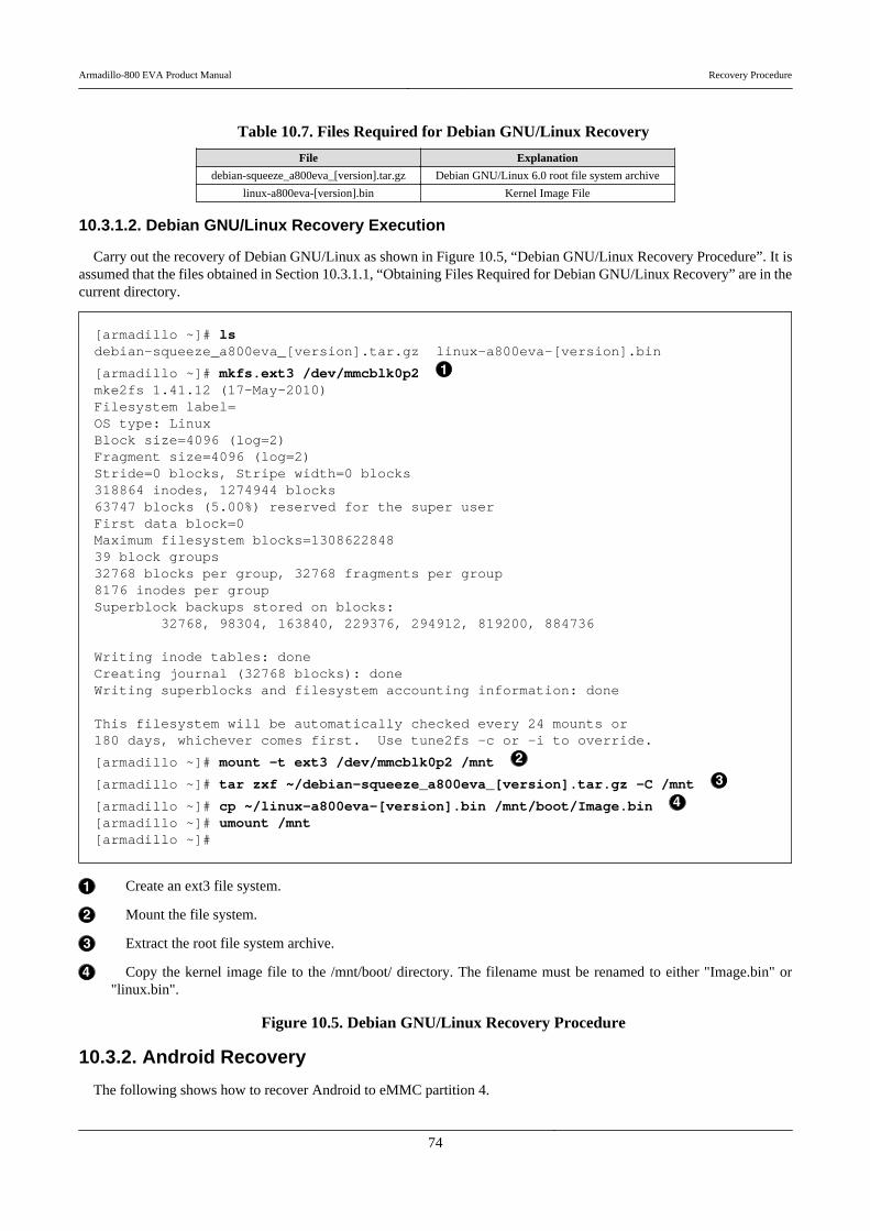
Table 10.7. Files Required for Debian GNU/Linux Recovery
File Explanation
debian-squeeze_a800eva_[version].tar.gz Debian GNU/Linux 6.0 root file system archive
linux-a800eva-[version].bin Kernel Image File
10.3.1.2. Debian GNU/Linux Recovery Execution
Carry out the recovery of Debian GNU/Linux as shown in Figure 10.5, “Debian GNU/Linux Recovery Procedure”. It isassumed that the files obtained in Section 10.3.1.1, “Obtaining Files Required for Debian GNU/Linux Recovery” are in thecurrent directory.
[armadillo ~]# lsdebian-squeeze_a800eva_[version].tar.gz linux-a800eva-[version].bin
[armadillo ~]# mkfs.ext3 /dev/mmcblk0p2 mke2fs 1.41.12 (17-May-2010)Filesystem label=OS type: LinuxBlock size=4096 (log=2)Fragment size=4096 (log=2)Stride=0 blocks, Stripe width=0 blocks318864 inodes, 1274944 blocks63747 blocks (5.00%) reserved for the super userFirst data block=0Maximum filesystem blocks=130862284839 block groups32768 blocks per group, 32768 fragments per group8176 inodes per groupSuperblock backups stored on blocks: 32768, 98304, 163840, 229376, 294912, 819200, 884736
Writing inode tables: doneCreating journal (32768 blocks): doneWriting superblocks and filesystem accounting information: done
This filesystem will be automatically checked every 24 mounts or180 days, whichever comes first. Use tune2fs -c or -i to override.
[armadillo ~]# mount -t ext3 /dev/mmcblk0p2 /mnt
[armadillo ~]# tar zxf ~/debian-squeeze_a800eva_[version].tar.gz -C /mnt
[armadillo ~]# cp ~/linux-a800eva-[version].bin /mnt/boot/Image.bin [armadillo ~]# umount /mnt[armadillo ~]#
Create an ext3 file system.
Mount the file system.
Extract the root file system archive.
Copy the kernel image file to the /mnt/boot/ directory. The filename must be renamed to either "Image.bin" or"linux.bin".
Figure 10.5. Debian GNU/Linux Recovery Procedure
10.3.2. Android Recovery
The following shows how to recover Android to eMMC partition 4.
Armadillo-800 EVA Product Manual Recovery Procedure
74
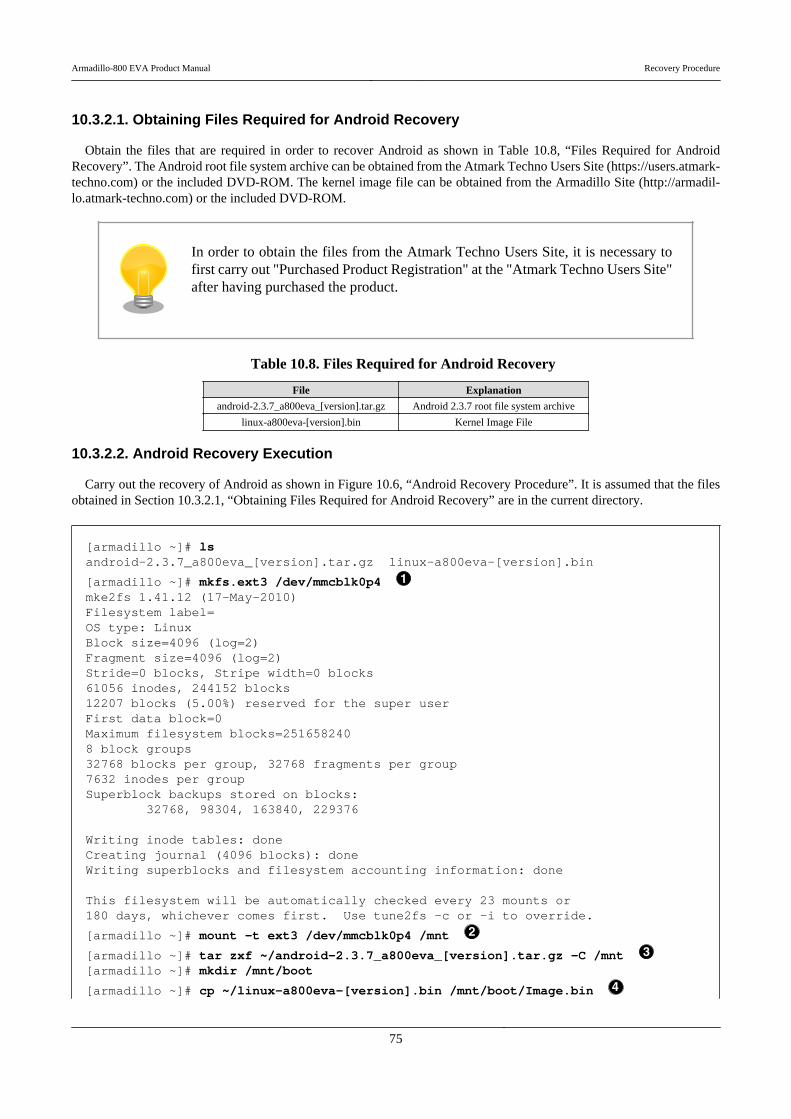
10.3.2.1. Obtaining Files Required for Android Recovery
Obtain the files that are required in order to recover Android as shown in Table 10.8, “Files Required for AndroidRecovery”. The Android root file system archive can be obtained from the Atmark Techno Users Site (https://users.atmark-techno.com) or the included DVD-ROM. The kernel image file can be obtained from the Armadillo Site (http://armadil-lo.atmark-techno.com) or the included DVD-ROM.
In order to obtain the files from the Atmark Techno Users Site, it is necessary tofirst carry out "Purchased Product Registration" at the "Atmark Techno Users Site"after having purchased the product.
Table 10.8. Files Required for Android Recovery
File Explanation
android-2.3.7_a800eva_[version].tar.gz Android 2.3.7 root file system archive
linux-a800eva-[version].bin Kernel Image File
10.3.2.2. Android Recovery Execution
Carry out the recovery of Android as shown in Figure 10.6, “Android Recovery Procedure”. It is assumed that the filesobtained in Section 10.3.2.1, “Obtaining Files Required for Android Recovery” are in the current directory.
[armadillo ~]# lsandroid-2.3.7_a800eva_[version].tar.gz linux-a800eva-[version].bin
[armadillo ~]# mkfs.ext3 /dev/mmcblk0p4 mke2fs 1.41.12 (17-May-2010)Filesystem label=OS type: LinuxBlock size=4096 (log=2)Fragment size=4096 (log=2)Stride=0 blocks, Stripe width=0 blocks61056 inodes, 244152 blocks12207 blocks (5.00%) reserved for the super userFirst data block=0Maximum filesystem blocks=2516582408 block groups32768 blocks per group, 32768 fragments per group7632 inodes per groupSuperblock backups stored on blocks: 32768, 98304, 163840, 229376
Writing inode tables: doneCreating journal (4096 blocks): doneWriting superblocks and filesystem accounting information: done
This filesystem will be automatically checked every 23 mounts or180 days, whichever comes first. Use tune2fs -c or -i to override.
[armadillo ~]# mount -t ext3 /dev/mmcblk0p4 /mnt
[armadillo ~]# tar zxf ~/android-2.3.7_a800eva_[version].tar.gz -C /mnt [armadillo ~]# mkdir /mnt/boot
[armadillo ~]# cp ~/linux-a800eva-[version].bin /mnt/boot/Image.bin
Armadillo-800 EVA Product Manual Recovery Procedure
75
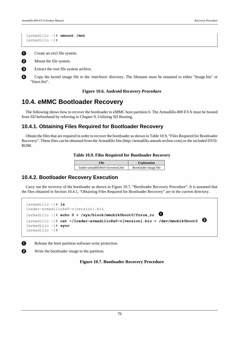
[armadillo ~]# umount /mnt[armadillo ~]#
Create an ext3 file system.
Mount the file system.
Extract the root file system archive.
Copy the kernel image file to the /mnt/boot/ directory. The filename must be renamed to either "Image.bin" or"linux.bin".
Figure 10.6. Android Recovery Procedure
10.4. eMMC Bootloader RecoveryThe following shows how to recover the bootloader to eMMC boot partition 0. The Armadillo-800 EVA must be booted
from SD beforehand by referring to Chapter 9, Utilizing SD Booting.
10.4.1. Obtaining Files Required for Bootloader Recovery
Obtain the files that are required in order to recover the bootloader as shown in Table 10.9, “Files Required for BootloaderRecovery”. These files can be obtained from the Armadillo Site (http://armadillo.atmark-techno.com) or the included DVD-ROM.
Table 10.9. Files Required for Bootloader Recovery
File Explanation
loader-armadillo8x0-v[version].bin Bootloader image file
10.4.2. Bootloader Recovery Execution
Carry out the recovery of the bootloader as shown in Figure 10.7, “Bootloader Recovery Procedure”. It is assumed thatthe files obtained in Section 10.4.1, “Obtaining Files Required for Bootloader Recovery” are in the current directory.
[armadillo ~]# lsloader-armadillo8x0-v[version].bin
[armadillo ~]# echo 0 > /sys/block/mmcblk0boot0/force_ro
[armadillo ~]# cat ~/loader-armadillo8x0-v[version].bin > /dev/mmcblk0boot0 [armadillo ~]# sync[armadillo ~]#
Release the boot partition software write protection.
Write the bootloader image to the partition.
Figure 10.7. Bootloader Recovery Procedure
Armadillo-800 EVA Product Manual Recovery Procedure
76
Chapter 11. Development EnvironmentSetup
This chapter explains how to setup a development environment on the work PC in order to carry out software develop-ment for Armadillo-800 EVA.
If the work PC is Debian GNU/Linux 6.0 (codename squeeze)[1], then a software development environment for Arma-dillo-800 EVA can be setup by installing the cross development tools. For information on how to install the cross devel-opment tools, please refer to Section 11.2, “Installing Cross Development Tools”.
If the work PC is Windows or a version of Linux other than Debian GNU/Linux 6.0 (codename squeeze), then a soft-ware development environment for Armadillo-800 EVA can be setup by using "ATDE (Atmark Techno DevelopmentEnvironment)". For information on how to use ATDE, please refer to Section 11.1, “Using ATDE”.
11.1. Using ATDEThe following covers how to use ATDE on the work PC.
ATDE is a VMware virtual machine data image that provides the Armadillo development environment. ATDE4, whichsupports software development for Armadillo-800 EVA, is based on Debian GNU/Linux 6.0 (codename squeeze) with crossdevelopment tools and other required tools already installed.
For information on obtaining and installing VMware, please refer to VMware's web page (http://www.vmware.com/).
VMware offers a number of products, from free versions for non-commercial useto paid commercial use versions. Separate licenses and end-user license agreements(EULA) exist for each product, so please choose the most appropriate product afterhaving fully checked these.
11.1.1. Obtaining ATDE
The ATDE4 archives shown in Table 11.1, “ATDE4 Types” can be obtained from the Armadillo Site (http://armadil-lo.atmark-techno.com) or the included DVD-ROM.
Table 11.1. ATDE4 Types
ATDE4 Archive The Base Debian GNU/Linux
atde4-[version]-amd64.zip Debian GNU/Linux 6.0 for the 64-bit PC (amd64) architecture
atde4-[version]-i386.zip Debian GNU/Linux 6.0 for the 32-bit PC (i386) architecture
[1]While it is possible to develop on other versions of Linux, not everything will work in exactly the same way as described in this document. If doingso, please take full responsibility and adjust the work to your environment.
Armadillo-800 EVA Product Manual Development Environment Setup
77
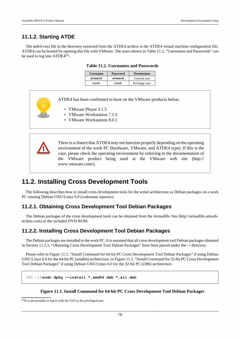
11.1.2. Starting ATDE
The atde4.vmx file in the directory extracted from the ATDE4 archive is the ATDE4 virtual machine configuration file.ATDE4 can be booted by opening this file with VMware. The users shown in Table 11.2, “Usernames and Passwords” canbe used to log into ATDE4[2].
Table 11.2. Usernames and Passwords
Username Password Permissionsatmark atmark General user
root root Privilege user
ATDE4 has been confirmed to boot on the VMware products below.
• VMware Player 3.1.5• VMware Workstation 7.1.5• VMware Workstation 8.0.1
There is a chance that ATDE4 may not function properly depending on the operatingenvironment of the work PC (hardware, VMware, and ATDE4 type). If this is thecase, please check the operating environment by referring to the documentation ofthe VMware product being used at the VMware web site (http://www.vmware.com/).
11.2. Installing Cross Development ToolsThe following describes how to install cross development tools for the armel architecture as Debian packages on a work
PC running Debian GNU/Linux 6.0 (codename squeeze).
11.2.1. Obtaining Cross Development Tool Debian Packages
The Debian packages of the cross development tools can be obtained from the Armadillo Site (http://armadillo.atmark-techno.com) or the included DVD-ROM.
11.2.2. Installing Cross Development Tool Debian Packages
The Debian packages are installed to the work PC. It is assumed that all cross development tool Debian packages obtainedin Section 11.2.1, “Obtaining Cross Development Tool Debian Packages” have been placed under the ~/ directory.
Please refer to Figure 11.1, “Install Command for 64-bit PC Cross Development Tool Debian Packages” if using DebianGNU/Linux 6.0 for the 64-bit PC (amd64) architecture, or Figure 11.2, “Install Command for 32-bit PC Cross DevelopmentTool Debian Packages” if using Debian GNU/Linux 6.0 for the 32-bit PC (i386) architecture.
[PC ~]$sudo dpkg --install *_amd64.deb *_all.deb
Figure 11.1. Install Command for 64-bit PC Cross Development Tool Debian Packages
[2]It is not possible to log in with the GUI as the privileged user.
Armadillo-800 EVA Product Manual Development Environment Setup
78

[PC ~]$sudo dpkg --install *_i386.deb *_all.deb
Figure 11.2. Install Command for 32-bit PC Cross Development Tool Debian Packages
If a cross development environment for the same target architecture has alreadybeen installed on the work PC, please make sure to first uninstall this existing en-vironment before installing the new cross development environment.
Armadillo-800 EVA Product Manual Development Environment Setup
79
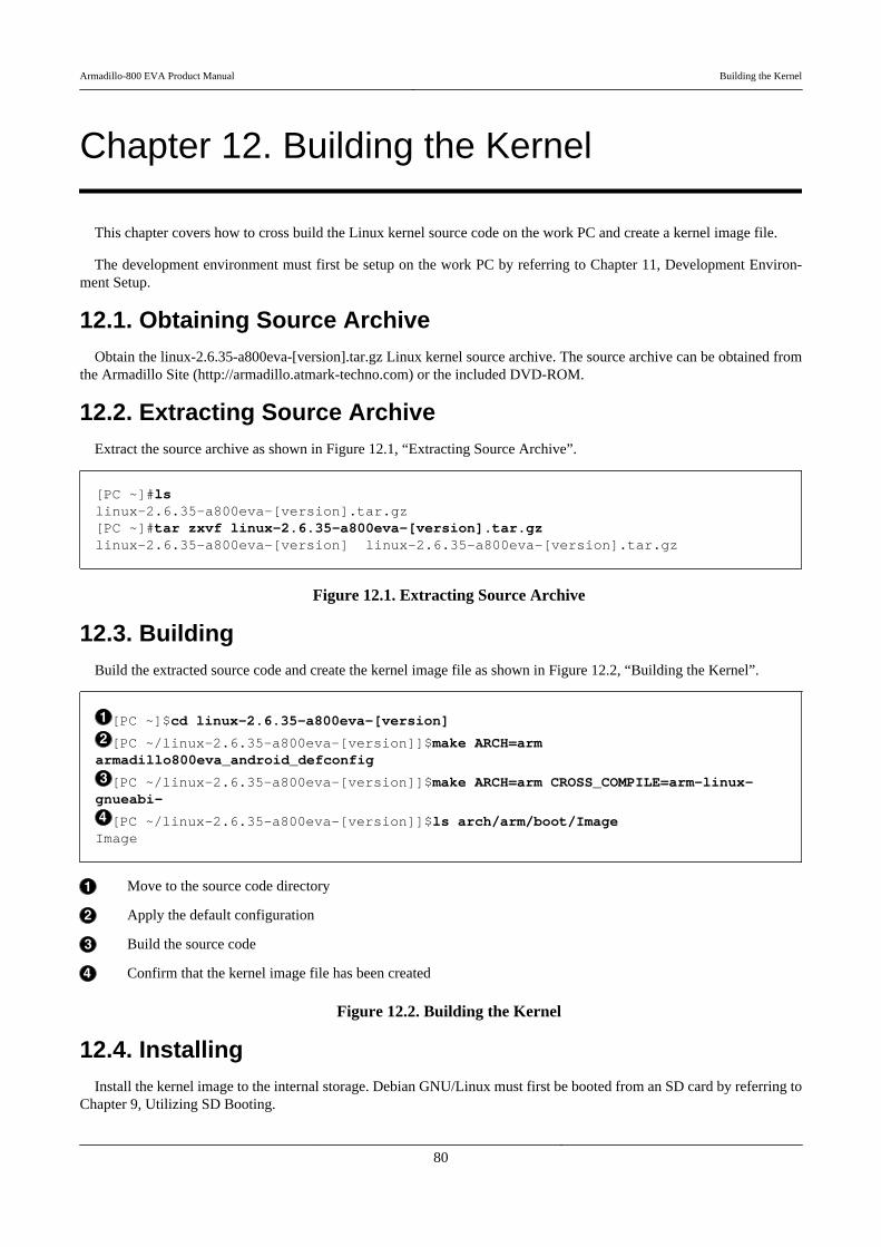
Chapter 12. Building the Kernel
This chapter covers how to cross build the Linux kernel source code on the work PC and create a kernel image file.
The development environment must first be setup on the work PC by referring to Chapter 11, Development Environ-ment Setup.
12.1. Obtaining Source ArchiveObtain the linux-2.6.35-a800eva-[version].tar.gz Linux kernel source archive. The source archive can be obtained from
the Armadillo Site (http://armadillo.atmark-techno.com) or the included DVD-ROM.
12.2. Extracting Source ArchiveExtract the source archive as shown in Figure 12.1, “Extracting Source Archive”.
[PC ~]#lslinux-2.6.35-a800eva-[version].tar.gz[PC ~]#tar zxvf linux-2.6.35-a800eva-[version].tar.gzlinux-2.6.35-a800eva-[version] linux-2.6.35-a800eva-[version].tar.gz
Figure 12.1. Extracting Source Archive
12.3. BuildingBuild the extracted source code and create the kernel image file as shown in Figure 12.2, “Building the Kernel”.
[PC ~]$cd linux-2.6.35-a800eva-[version]
[PC ~/linux-2.6.35-a800eva-[version]]$make ARCH=arm ⏎armadillo800eva_android_defconfig
[PC ~/linux-2.6.35-a800eva-[version]]$make ARCH=arm CROSS_COMPILE=arm-linux- ⏎gnueabi-
[PC ~/linux-2.6.35-a800eva-[version]]$ls arch/arm/boot/ImageImage
Move to the source code directory
Apply the default configuration
Build the source code
Confirm that the kernel image file has been created
Figure 12.2. Building the Kernel
12.4. InstallingInstall the kernel image to the internal storage. Debian GNU/Linux must first be booted from an SD card by referring to
Chapter 9, Utilizing SD Booting.
Armadillo-800 EVA Product Manual Building the Kernel
80
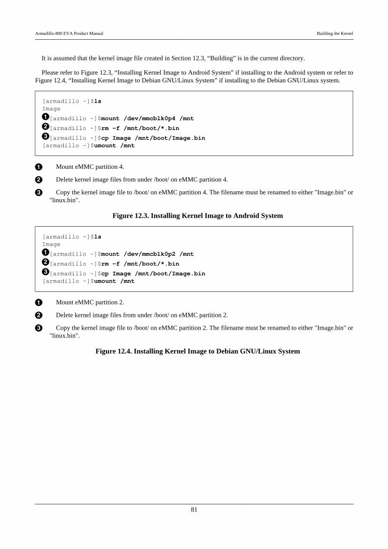
It is assumed that the kernel image file created in Section 12.3, “Building” is in the current directory.
Please refer to Figure 12.3, “Installing Kernel Image to Android System” if installing to the Android system or refer toFigure 12.4, “Installing Kernel Image to Debian GNU/Linux System” if installing to the Debian GNU/Linux system.
[armadillo ~]$lsImage
[armadillo ~]$mount /dev/mmcblk0p4 /mnt
[armadillo ~]$rm -f /mnt/boot/*.bin
[armadillo ~]$cp Image /mnt/boot/Image.bin[armadillo ~]$umount /mnt
Mount eMMC partition 4.
Delete kernel image files from under /boot/ on eMMC partition 4.
Copy the kernel image file to /boot/ on eMMC partition 4. The filename must be renamed to either "Image.bin" or"linux.bin".
Figure 12.3. Installing Kernel Image to Android System
[armadillo ~]$lsImage
[armadillo ~]$mount /dev/mmcblk0p2 /mnt
[armadillo ~]$rm -f /mnt/boot/*.bin
[armadillo ~]$cp Image /mnt/boot/Image.bin[armadillo ~]$umount /mnt
Mount eMMC partition 2.
Delete kernel image files from under /boot/ on eMMC partition 2.
Copy the kernel image file to /boot/ on eMMC partition 2. The filename must be renamed to either "Image.bin" or"linux.bin".
Figure 12.4. Installing Kernel Image to Debian GNU/Linux System
Armadillo-800 EVA Product Manual Building the Kernel
81
Chapter 13. Building the SGX KernelModules
This chapter covers how to cross build the PowerVR SGX DDK (Driver Development Kit) source code on the workPC and create the kernel modules.
When using a kernel image with Android that has had changes to configurationsuch as Kernel features which have a large effect on the kernel structure, in rarecases the SGX kernel modules may stop functioning. When using a customizedkernel, SGX kernel modules must be made for that kernel.
The development environment must first be setup on the work PC by referring to Chapter 11, Development Environ-ment Setup.
13.1. Obtaining Source ArchiveObtain the eurasia_km-[version].tar.gz SGX DDK source code archive. The source archive can be obtained from the
included DVD-ROM.
13.2. Preparing KernelKernel source code that has been previously built is required in order to build the SGX kernel modules. Build the kernel
source code by referring to Chapter 12, Building the Kernel.
13.3. BuildingExtract the source archive obtained in Section 13.1, “Obtaining Source Archive” and build it after having configured the
parameters to suit the build environment. The commands below assume that the kernel source code built in Section 13.2,“Preparing Kernel” is in the ~/linux-2.6.35-a800eva directory.
dos2unix is used for the SGX kernel modules build. If it is not installed on the workPC, please install it as shown below.
[PC ~]# apt-get update[PC ~]# apt-get install dos2unix
Armadillo-800 EVA Product Manual Building the SGX Kernel Modules
82
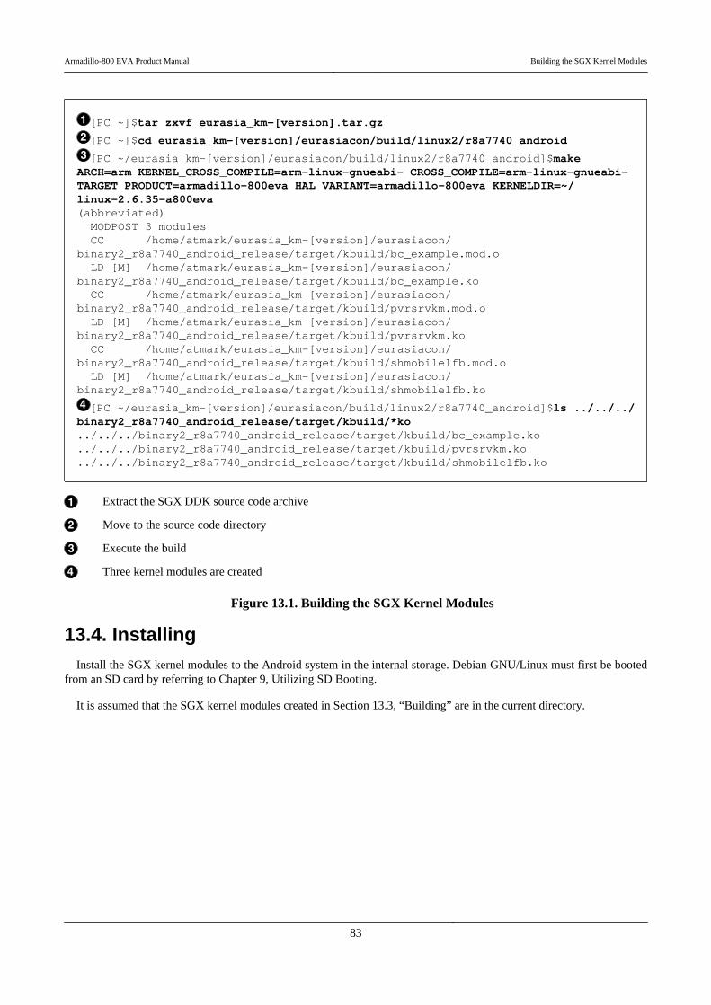
[PC ~]$tar zxvf eurasia_km-[version].tar.gz
[PC ~]$cd eurasia_km-[version]/eurasiacon/build/linux2/r8a7740_android
[PC ~/eurasia_km-[version]/eurasiacon/build/linux2/r8a7740_android]$make ⏎ARCH=arm KERNEL_CROSS_COMPILE=arm-linux-gnueabi- CROSS_COMPILE=arm-linux-gnueabi- ⏎TARGET_PRODUCT=armadillo-800eva HAL_VARIANT=armadillo-800eva KERNELDIR=~/ ⏎linux-2.6.35-a800eva(abbreviated) MODPOST 3 modules CC /home/atmark/eurasia_km-[version]/eurasiacon/ ⏎binary2_r8a7740_android_release/target/kbuild/bc_example.mod.o LD [M] /home/atmark/eurasia_km-[version]/eurasiacon/ ⏎binary2_r8a7740_android_release/target/kbuild/bc_example.ko CC /home/atmark/eurasia_km-[version]/eurasiacon/ ⏎binary2_r8a7740_android_release/target/kbuild/pvrsrvkm.mod.o LD [M] /home/atmark/eurasia_km-[version]/eurasiacon/ ⏎binary2_r8a7740_android_release/target/kbuild/pvrsrvkm.ko CC /home/atmark/eurasia_km-[version]/eurasiacon/ ⏎binary2_r8a7740_android_release/target/kbuild/shmobilelfb.mod.o LD [M] /home/atmark/eurasia_km-[version]/eurasiacon/ ⏎binary2_r8a7740_android_release/target/kbuild/shmobilelfb.ko
[PC ~/eurasia_km-[version]/eurasiacon/build/linux2/r8a7740_android]$ls ../../../ ⏎binary2_r8a7740_android_release/target/kbuild/*ko../../../binary2_r8a7740_android_release/target/kbuild/bc_example.ko../../../binary2_r8a7740_android_release/target/kbuild/pvrsrvkm.ko../../../binary2_r8a7740_android_release/target/kbuild/shmobilelfb.ko
Extract the SGX DDK source code archive
Move to the source code directory
Execute the build
Three kernel modules are created
Figure 13.1. Building the SGX Kernel Modules
13.4. InstallingInstall the SGX kernel modules to the Android system in the internal storage. Debian GNU/Linux must first be booted
from an SD card by referring to Chapter 9, Utilizing SD Booting.
It is assumed that the SGX kernel modules created in Section 13.3, “Building” are in the current directory.
Armadillo-800 EVA Product Manual Building the SGX Kernel Modules
83
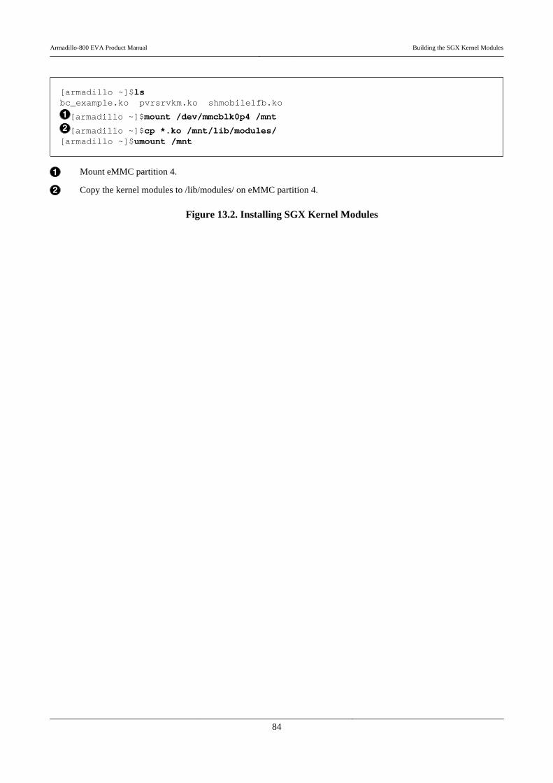
[armadillo ~]$lsbc_example.ko pvrsrvkm.ko shmobilelfb.ko
[armadillo ~]$mount /dev/mmcblk0p4 /mnt
[armadillo ~]$cp *.ko /mnt/lib/modules/[armadillo ~]$umount /mnt
Mount eMMC partition 4.
Copy the kernel modules to /lib/modules/ on eMMC partition 4.
Figure 13.2. Installing SGX Kernel Modules
Armadillo-800 EVA Product Manual Building the SGX Kernel Modules
84

Chapter 14. Building the Wireless LAN(AWL13) Linux Device Driver
This chapter covers how to cross build the device driver source code for the Armadillo-WLAN (AWL13) wirelessLAN module on the work PC and create the kernel module.
The development environment must first be setup on the work PC by referring to Chapter 11, Development Environ-ment Setup.
14.1. Obtaining Source ArchiveObtain the awl13-[version].tar.gz AWL13 device driver source archive. The source archive can be obtained from the
Armadillo Site (http://armadillo.atmark-techno.com) or the included DVD-ROM.
14.2. Preparing KernelKernel source code that has been previously built is required in order to build the AWL13 device driver source code.
Build the kernel source code by referring to Chapter 12, Building the Kernel. The following configuration must be enabled.[1]
• CONFIG_MMC• CONFIG_SYSFS• CONFIG_WIRELESS_EXT
14.3. BuildingExtract the source archive obtained in Section 14.1, “Obtaining Source Archive” and build it after having configured the
parameters to suit the build environment. The commands below assume that the kernel source code built in Section 14.2,“Preparing Kernel” is in the ~/linux-2.6.35-a800eva-[version] directory.
[1]Enabled in the default Armadillo-800 EVA configuration.
Armadillo-800 EVA Product Manual Building the Wireless LAN (AWL13) Linux Device Driver
85

[PC ~]$tar zxvf awl13-[version].tar.gz
[PC ~]$cd awl13-[version]
[PC ~/awl13-[version]]$AWL13_DEVICE=SDIO make ARCH=arm CROSS_COMPILE=arm-linux- ⏎gnueabi- KERNELDIR=~/linux-2.6.35-a800eva-[version]make -C ../linux-2.6.35-a800eva-[version]/ M=/home/atmark/aerial-awl13 modulesmake[1]: Entering directory `/home/atmark/linux-2.6.35-a800eva-[version]' CC [M] /home/atmark/aerial-awl13/src/awl13_log.o CC [M] /home/atmark/aerial-awl13/src/awl13_sdiodrv.o CC [M] /home/atmark/aerial-awl13/src/awl13_ioctl.o CC [M] /home/atmark/aerial-awl13/src/awl13_fw.o CC [M] /home/atmark/aerial-awl13/src/awl13_sysfs.o CC [M] /home/atmark/aerial-awl13/src/awl13_wid.o LD [M] /home/atmark/aerial-awl13/src/awl13_sdio.o Building modules, stage 2. MODPOST 1 modules CC /home/atmark/aerial-awl13/src/awl13_sdio.mod.o LD [M] /home/atmark/aerial-awl13/src/awl13_sdio.komake[1]: Leaving directory `/home/atmark/linux-2.6.35-a800eva-[version]'
[PC ~/awl13-[version]]$ls src/awl13_sdio.ko awl13_sdio.ko
Extract the AWL13 source code archive
Move to the source code directory
Execute the build
The awl13_sdio.ko kernel module has been created
Figure 14.1. Building the AWL13 Driver
Specify the host interface for AWL13_DEVICE. On Armadillo-800 EVA theAWL13 is configured to operate in SDIO boot mode.
14.4. InstallingInstall the AWL13 kernel module to the Debian GNU/Linux system in the internal storage. Debian GNU/Linux must
first be booted from an SD card by referring to Chapter 9, Utilizing SD Booting.
It is assumed that the AWL13 kernel module created in Section 14.3, “Building” is in the current directory.
Armadillo-800 EVA Product Manual Building the Wireless LAN (AWL13) Linux Device Driver
86

[armadillo ~]$lsawl13_sdio.ko
[armadillo ~]$mount /dev/mmcblk0p2 /mnt
[armadillo ~]$cp awl13_sdio.ko /lib/modules/$(uname -r)/awl13/[armadillo ~]$umount /mnt
Mount eMMC partition 2.
Copy the kernel module to /lib/modules/$(uname -r)/awl13/ on eMMC partition 2.
Figure 14.2. Installing AWL13 Kernel Module
Armadillo-800 EVA Product Manual Building the Wireless LAN (AWL13) Linux Device Driver
87
Chapter 15. Building the Bootloader
This chapter covers how to cross build the bootloader source code on the work PC and create a bootloader image file.
The development environment must first be setup on the work PC by referring to Chapter 11, Development Environ-ment Setup.
15.1. Obtaining Source ArchiveObtain the hermit-at-[version]-source.tar.gz bootloader source archive. The source archive can be obtained from the
Armadillo Site (http://armadillo.atmark-techno.com) or the included DVD-ROM.
Hermit-At v3 series is used for the Armadillo-800 EVA bootloader.
15.2. Extracting Source ArchiveExtract the obtained source archive as shown in Figure 15.1, “Extracting Source Archive”.
[PC ~]#lshermit-at-[version]-source.tar.gz[PC ~]#tar zxvf hermit-at-[version]-source.tar.gzhermit-at-[version] hermit-at-[version]-source.tar.gz
Figure 15.1. Extracting Source Archive
15.3. BuildingBuild the extracted source archive to create the bootloader image file as shown in Figure 15.2, “Building the Bootloader”.
Armadillo-800 EVA Product Manual Building the Bootloader
88
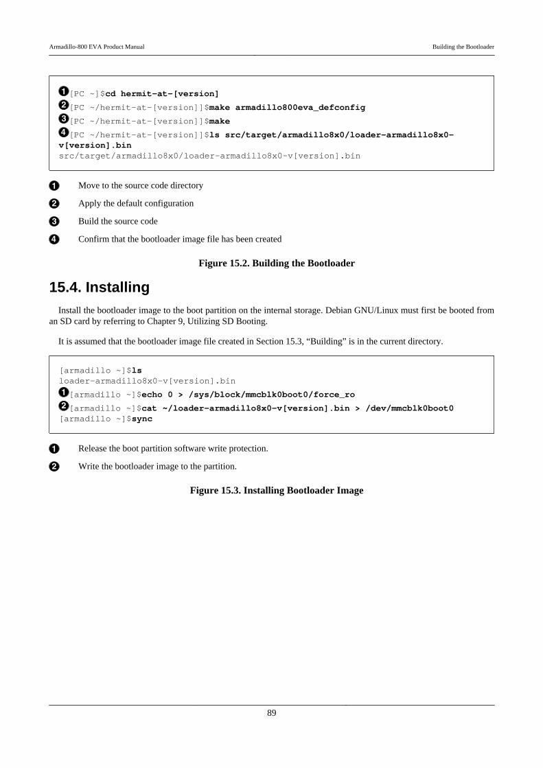
[PC ~]$cd hermit-at-[version]
[PC ~/hermit-at-[version]]$make armadillo800eva_defconfig
[PC ~/hermit-at-[version]]$make
[PC ~/hermit-at-[version]]$ls src/target/armadillo8x0/loader-armadillo8x0- ⏎v[version].binsrc/target/armadillo8x0/loader-armadillo8x0-v[version].bin
Move to the source code directory
Apply the default configuration
Build the source code
Confirm that the bootloader image file has been created
Figure 15.2. Building the Bootloader
15.4. InstallingInstall the bootloader image to the boot partition on the internal storage. Debian GNU/Linux must first be booted from
an SD card by referring to Chapter 9, Utilizing SD Booting.
It is assumed that the bootloader image file created in Section 15.3, “Building” is in the current directory.
[armadillo ~]$lsloader-armadillo8x0-v[version].bin
[armadillo ~]$echo 0 > /sys/block/mmcblk0boot0/force_ro
[armadillo ~]$cat ~/loader-armadillo8x0-v[version].bin > /dev/mmcblk0boot0[armadillo ~]$sync
Release the boot partition software write protection.
Write the bootloader image to the partition.
Figure 15.3. Installing Bootloader Image
Armadillo-800 EVA Product Manual Building the Bootloader
89

Chapter 16. Using JTAG ICE
This chapter explains how to connect a JTAG ICE in order to carry out ARM debugging.
16.1. Preparation
16.1.1. JTAG Cable Connections
Connect the JTAG ICE cable to the ARM JTAG interface (standard ARM 20-pin connector). For detailed informationon the signal layout and so on, please refer to Section 18.6, “CON6 (ARM JTAG Interface)”.
16.1.2. DIP Switch Configuration
Set the DIP switch JTAG configuration to ARM. Please refer to Figure 16.1, “DIP Switch JTAG Configuration (ARM)”and set JTAG Configuration 1 (SW1.7) to on and JTAG Configuration 2 (SW1.8) to off.
Figure 16.1. DIP Switch JTAG Configuration (ARM)
16.2. Connection ConfirmationOnce configured in accordance with Section 16.1, “Preparation”, the CPU will be seen as shown below.
Item Value
Device ID 0x4BA00477
Command Length 4
16.3. Debugger SupportFor information on whether or not your debugger supports Armadillo-800 EVA, please contact the debugger maker.
Armadillo-800 EVA Product Manual Using JTAG ICE
90
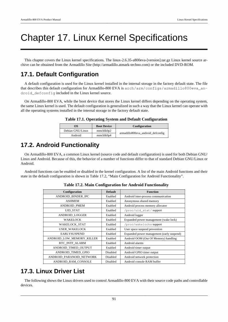
Chapter 17. Linux Kernel Specifications
This chapter covers the Linux kernel specifications. The linux-2.6.35-a800eva-[version].tar.gz Linux kernel source ar-chive can be obtained from the Armadillo Site (http://armadillo.atmark-techno.com) or the included DVD-ROM.
17.1. Default ConfigurationA default configuration is used for the Linux kernel installed in the internal storage in the factory default state. The file
that describes this default configuration for Armadillo-800 EVA is arch/arm/configs/armadillo800eva_an-droid_defconfig included in the Linux kernel source.
On Armadillo-800 EVA, while the boot device that stores the Linux kernel differs depending on the operating system,the same Linux kernel is used. The default configuration is generalized in such a way that the Linux kernel can operate withall the operating systems installed in the internal storage in the factory default state.
Table 17.1. Operating System and Default Configuration
OS Boot Device Configuration
Debian GNU/Linux mmcblk0p2armadillo800eva_android_defconfig
Android mmcblk0p4
17.2. Android FunctionalityOn Armadillo-800 EVA, a common Linux kernel (source code and default configuration) is used for both Debian GNU/
Linux and Android. Because of this, the behavior of a number of functions differ to that of standard Debian GNU/Linux orAndroid.
Android functions can be enabled or disabled in the kernel configuration. A list of the main Android functions and theirstate in the default configuration is shown in Table 17.2, “Main Configuration for Android Functionality”.
Table 17.2. Main Configuration for Android Functionality
Configuration Default Function
ANDROID_BINDER_IPC Enabled Android inter-process communication
ASHMEM Enabled Anonymous shared memory
ANDROID_PMEM Enabled Android process memory allocator
UID_STAT Enabled /proc/uid_stat/ support
ANDROID_LOGGER Enabled Android logger
WAKELOCK Enabled Expanded power management (wake lock)
WAKELOCK_STAT Enabled /proc/wakelocks support
USER_WAKELOCK Enabled User space suspend prevention
EARLYSUSPEND Enabled Expanded power management (early suspend)
ANDROID_LOW_MEMORY_KILLER Enabled Android OOM (Out Of Memory) handling
RTC_INTF_ALARM Enabled Android alarms
ANDROID_TIMED_OUTPUT Enabled Android timer output
ANDROID_TIMED_GPIO Disabled Android GPIO timer output
ANDROID_PARANOID_NETWORK Disabled Android network protection
ANDROID_RAM_CONSOLE Disabled Android console RAM buffer
17.3. Linux Driver ListThe following shows the Linux drivers used to control Armadillo-800 EVA with their source code paths and controllable
devices.
Armadillo-800 EVA Product Manual Linux Kernel Specifications
91
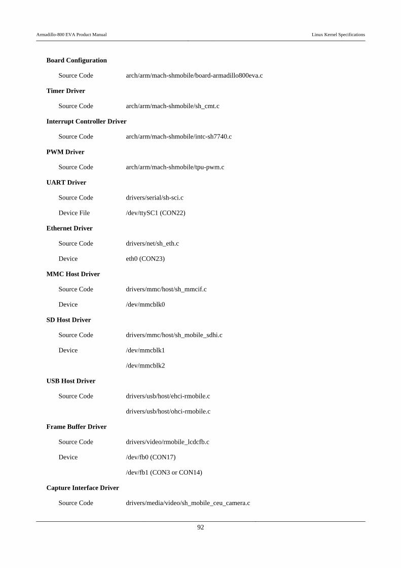
Board Configuration
Source Code arch/arm/mach-shmobile/board-armadillo800eva.c
Timer Driver
Source Code arch/arm/mach-shmobile/sh_cmt.c
Interrupt Controller Driver
Source Code arch/arm/mach-shmobile/intc-sh7740.c
PWM Driver
Source Code arch/arm/mach-shmobile/tpu-pwm.c
UART Driver
Source Code drivers/serial/sh-sci.c
Device File /dev/ttySC1 (CON22)
Ethernet Driver
Source Code drivers/net/sh_eth.c
Device eth0 (CON23)
MMC Host Driver
Source Code drivers/mmc/host/sh_mmcif.c
Device /dev/mmcblk0
SD Host Driver
Source Code drivers/mmc/host/sh_mobile_sdhi.c
Device /dev/mmcblk1
/dev/mmcblk2
USB Host Driver
Source Code drivers/usb/host/ehci-rmobile.c
drivers/usb/host/ohci-rmobile.c
Frame Buffer Driver
Source Code drivers/video/rmobile_lcdcfb.c
Device /dev/fb0 (CON17)
/dev/fb1 (CON3 or CON14)
Capture Interface Driver
Source Code drivers/media/video/sh_mobile_ceu_camera.c
Armadillo-800 EVA Product Manual Linux Kernel Specifications
92
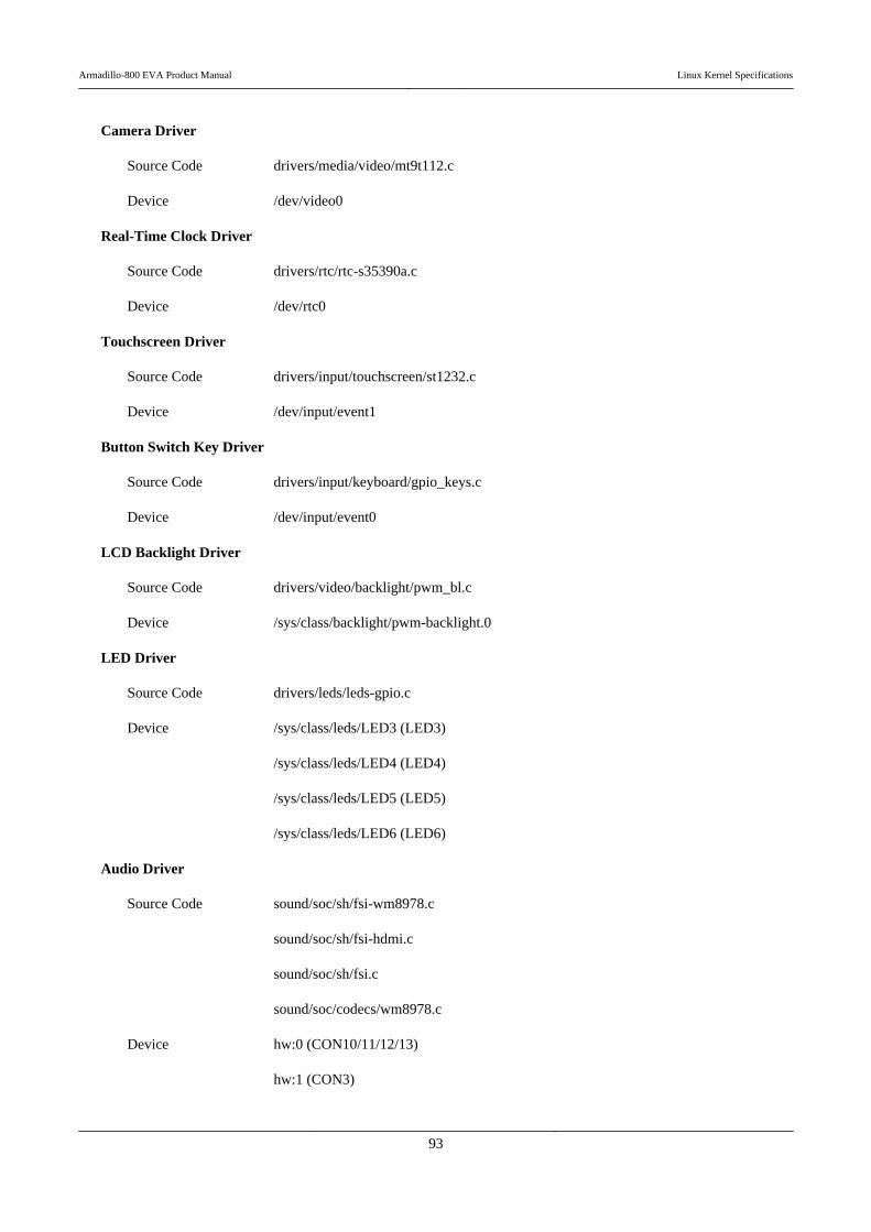
Camera Driver
Source Code drivers/media/video/mt9t112.c
Device /dev/video0
Real-Time Clock Driver
Source Code drivers/rtc/rtc-s35390a.c
Device /dev/rtc0
Touchscreen Driver
Source Code drivers/input/touchscreen/st1232.c
Device /dev/input/event1
Button Switch Key Driver
Source Code drivers/input/keyboard/gpio_keys.c
Device /dev/input/event0
LCD Backlight Driver
Source Code drivers/video/backlight/pwm_bl.c
Device /sys/class/backlight/pwm-backlight.0
LED Driver
Source Code drivers/leds/leds-gpio.c
Device /sys/class/leds/LED3 (LED3)
/sys/class/leds/LED4 (LED4)
/sys/class/leds/LED5 (LED5)
/sys/class/leds/LED6 (LED6)
Audio Driver
Source Code sound/soc/sh/fsi-wm8978.c
sound/soc/sh/fsi-hdmi.c
sound/soc/sh/fsi.c
sound/soc/codecs/wm8978.c
Device hw:0 (CON10/11/12/13)
hw:1 (CON3)
Armadillo-800 EVA Product Manual Linux Kernel Specifications
93
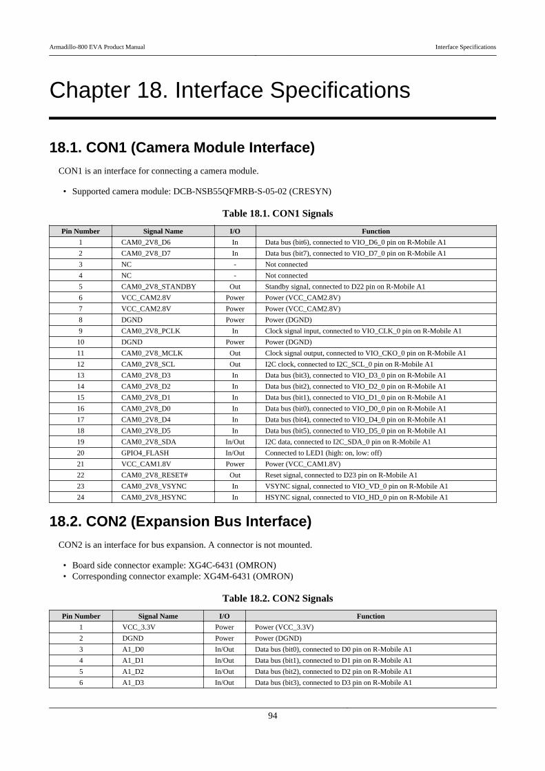
Chapter 18. Interface Specifications
18.1. CON1 (Camera Module Interface)CON1 is an interface for connecting a camera module.
• Supported camera module: DCB-NSB55QFMRB-S-05-02 (CRESYN)
Table 18.1. CON1 Signals
Pin Number Signal Name I/O Function
1 CAM0_2V8_D6 In Data bus (bit6), connected to VIO_D6_0 pin on R-Mobile A1
2 CAM0_2V8_D7 In Data bus (bit7), connected to VIO_D7_0 pin on R-Mobile A1
3 NC - Not connected
4 NC - Not connected
5 CAM0_2V8_STANDBY Out Standby signal, connected to D22 pin on R-Mobile A1
6 VCC_CAM2.8V Power Power (VCC_CAM2.8V)
7 VCC_CAM2.8V Power Power (VCC_CAM2.8V)
8 DGND Power Power (DGND)
9 CAM0_2V8_PCLK In Clock signal input, connected to VIO_CLK_0 pin on R-Mobile A1
10 DGND Power Power (DGND)
11 CAM0_2V8_MCLK Out Clock signal output, connected to VIO_CKO_0 pin on R-Mobile A1
12 CAM0_2V8_SCL Out I2C clock, connected to I2C_SCL_0 pin on R-Mobile A1
13 CAM0_2V8_D3 In Data bus (bit3), connected to VIO_D3_0 pin on R-Mobile A1
14 CAM0_2V8_D2 In Data bus (bit2), connected to VIO_D2_0 pin on R-Mobile A1
15 CAM0_2V8_D1 In Data bus (bit1), connected to VIO_D1_0 pin on R-Mobile A1
16 CAM0_2V8_D0 In Data bus (bit0), connected to VIO_D0_0 pin on R-Mobile A1
17 CAM0_2V8_D4 In Data bus (bit4), connected to VIO_D4_0 pin on R-Mobile A1
18 CAM0_2V8_D5 In Data bus (bit5), connected to VIO_D5_0 pin on R-Mobile A1
19 CAM0_2V8_SDA In/Out I2C data, connected to I2C_SDA_0 pin on R-Mobile A1
20 GPIO4_FLASH In/Out Connected to LED1 (high: on, low: off)
21 VCC_CAM1.8V Power Power (VCC_CAM1.8V)
22 CAM0_2V8_RESET# Out Reset signal, connected to D23 pin on R-Mobile A1
23 CAM0_2V8_VSYNC In VSYNC signal, connected to VIO_VD_0 pin on R-Mobile A1
24 CAM0_2V8_HSYNC In HSYNC signal, connected to VIO_HD_0 pin on R-Mobile A1
18.2. CON2 (Expansion Bus Interface)CON2 is an interface for bus expansion. A connector is not mounted.
• Board side connector example: XG4C-6431 (OMRON)• Corresponding connector example: XG4M-6431 (OMRON)
Table 18.2. CON2 Signals
Pin Number Signal Name I/O Function
1 VCC_3.3V Power Power (VCC_3.3V)
2 DGND Power Power (DGND)
3 A1_D0 In/Out Data bus (bit0), connected to D0 pin on R-Mobile A1
4 A1_D1 In/Out Data bus (bit1), connected to D1 pin on R-Mobile A1
5 A1_D2 In/Out Data bus (bit2), connected to D2 pin on R-Mobile A1
6 A1_D3 In/Out Data bus (bit3), connected to D3 pin on R-Mobile A1
Armadillo-800 EVA Product Manual Interface Specifications
94
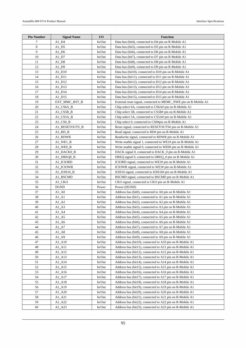
Pin Number Signal Name I/O Function
7 A1_D4 In/Out Data bus (bit4), connected to D4 pin on R-Mobile A1
8 A1_D5 In/Out Data bus (bit5), connected to D5 pin on R-Mobile A1
9 A1_D6 In/Out Data bus (bit6), connected to D6 pin on R-Mobile A1
10 A1_D7 In/Out Data bus (bit7), connected to D7 pin on R-Mobile A1
11 A1_D8 In/Out Data bus (bit8), connected to D8 pin on R-Mobile A1
12 A1_D9 In/Out Data bus (bit9), connected to D9 pin on R-Mobile A1
13 A1_D10 In/Out Data bus (bit10), connected to D10 pin on R-Mobile A1
14 A1_D11 In/Out Data bus (bit11), connected to D11 pin on R-Mobile A1
15 A1_D12 In/Out Data bus (bit12), connected to D12 pin on R-Mobile A1
16 A1_D13 In/Out Data bus (bit13), connected to D13 pin on R-Mobile A1
17 A1_D14 In/Out Data bus (bit14), connected to D14 pin on R-Mobile A1
18 A1_D15 In/Out Data bus (bit15), connected to D15 pin on R-Mobile A1
19 EXT_MMC_RST_B In/Out External reset signal, connected to MEMC_NWE pin on R-Mobile A1
20 A1_CS6A_B In/Out Chip select 6A, connected to CS6A# pin on R-Mobile A1
21 A1_CS5B_B In/Out Chip select 5B, connected to CS5B# pin on R-Mobile A1
22 A1_CS5A_B In/Out Chip select 5A, connected to CS5A# pin on R-Mobile A1
23 A1_CS0_B In/Out Chip select 0, connected to CS0#pin on R-Mobile A1
24 A1_RESETOUTS_B In/Out Reset signal, connected to RESETOUTS# pin on R-Mobile A1
25 A1_RD_B In/Out Read signal, connected to RD# pin on R-Mobile A1
26 A1_RDWR In/Out Readwrite signal, connected to RDWR pin on R-Mobile A1
27 A1_WE1_B In/Out Write enable signal 1, connected to WE1# pin on R-Mobile A1
28 A1_WE0_B In/Out Write enable signal 0, connected to WE0# pin on R-Mobile A1
29 A1_DACK0_B In/Out DACK signal 0, connected to DACK_0 pin on R-Mobile A1
30 A1_DREQ0_B In/Out DREQ signal 0, connected to DREQ_0 pin on R-Mobile A1
31 A1_ICIORD In/Out ICIORD signal, connected to WE2# pin on R-Mobile A1
32 A1_ICIOWR In/Out ICIOWR signal, connected to WE3# pin on R-Mobile A1
33 A1_IOIS16_B In/Out IOIS16 signal, connected to IOIS16# pin on R-Mobile A1
34 A1_BSCMD In/Out BSCMD signal, connected to BSCMD pin on R-Mobile A1
35 A1_CKO In/Out CKO signal, connected to CKO pin on R-Mobile A1
36 DGND Power Power (DGND)
37 A1_A0 In/Out Address bus (bit0), connected to A0 pin on R-Mobile A1
38 A1_A1 In/Out Address bus (bit1), connected to A1 pin on R-Mobile A1
39 A1_A2 In/Out Address bus (bit2), connected to A2 pin on R-Mobile A1
40 A1_A3 In/Out Address bus (bit3), connected to A3 pin on R-Mobile A1
41 A1_A4 In/Out Address bus (bit4), connected to A4 pin on R-Mobile A1
42 A1_A5 In/Out Address bus (bit5), connected to A5 pin on R-Mobile A1
43 A1_A6 In/Out Address bus (bit6), connected to A6 pin on R-Mobile A1
44 A1_A7 In/Out Address bus (bit7), connected to A7 pin on R-Mobile A1
45 A1_A8 In/Out Address bus (bit8), connected to A8 pin on R-Mobile A1
46 A1_A9 In/Out Address bus (bit9), connected to A9 pin on R-Mobile A1
47 A1_A10 In/Out Address bus (bit10), connected to A10 pin on R-Mobile A1
48 A1_A11 In/Out Address bus (bit11), connected to A11 pin on R-Mobile A1
49 A1_A12 In/Out Address bus (bit12), connected to A12 pin on R-Mobile A1
50 A1_A13 In/Out Address bus (bit13), connected to A13 pin on R-Mobile A1
51 A1_A14 In/Out Address bus (bit14), connected to A14 pin on R-Mobile A1
52 A1_A15 In/Out Address bus (bit15), connected to A15 pin on R-Mobile A1
53 A1_A16 In/Out Address bus (bit16), connected to A16 pin on R-Mobile A1
54 A1_A17 In/Out Address bus (bit17), connected to A17 pin on R-Mobile A1
55 A1_A18 In/Out Address bus (bit18), connected to A18 pin on R-Mobile A1
56 A1_A19 In/Out Address bus (bit19), connected to A19 pin on R-Mobile A1
57 A1_A20 In/Out Address bus (bit20), connected to A20 pin on R-Mobile A1
58 A1_A21 In/Out Address bus (bit21), connected to A21 pin on R-Mobile A1
59 A1_A22 In/Out Address bus (bit22), connected to A22 pin on R-Mobile A1
60 A1_A23 In/Out Address bus (bit23), connected to A23 pin on R-Mobile A1
Armadillo-800 EVA Product Manual Interface Specifications
95
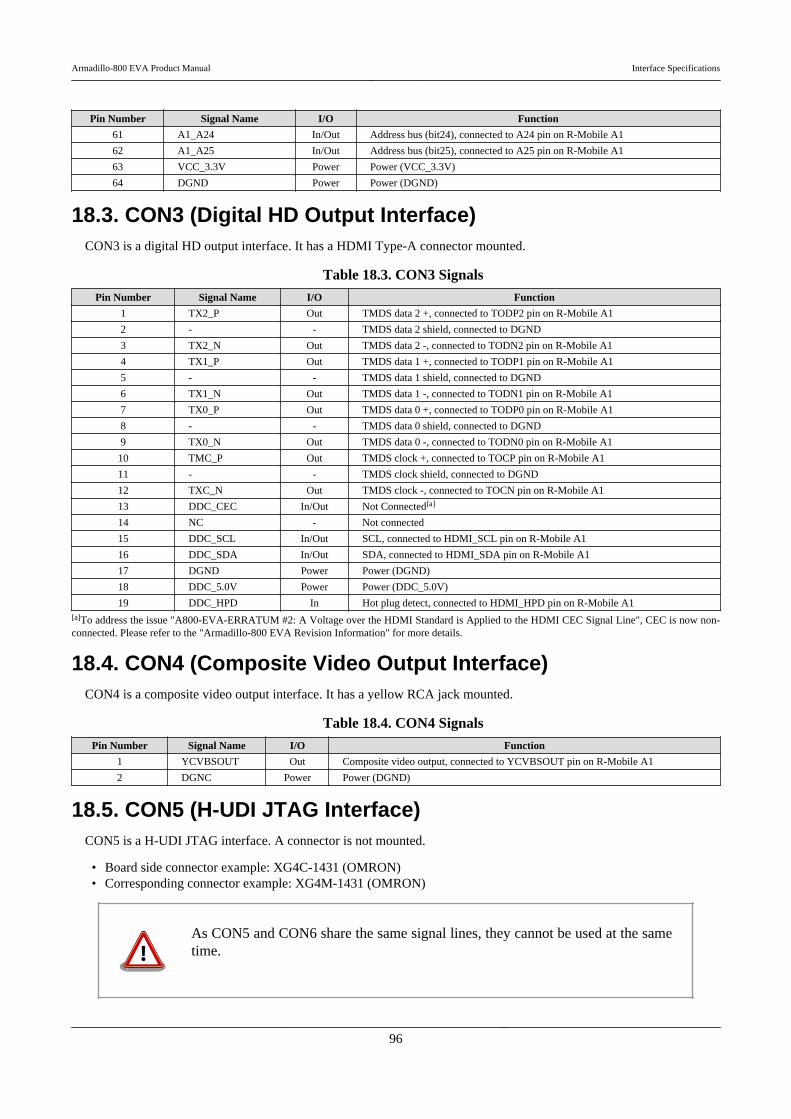
Pin Number Signal Name I/O Function
61 A1_A24 In/Out Address bus (bit24), connected to A24 pin on R-Mobile A1
62 A1_A25 In/Out Address bus (bit25), connected to A25 pin on R-Mobile A1
63 VCC_3.3V Power Power (VCC_3.3V)
64 DGND Power Power (DGND)
18.3. CON3 (Digital HD Output Interface)CON3 is a digital HD output interface. It has a HDMI Type-A connector mounted.
Table 18.3. CON3 Signals
Pin Number Signal Name I/O Function
1 TX2_P Out TMDS data 2 +, connected to TODP2 pin on R-Mobile A1
2 - - TMDS data 2 shield, connected to DGND
3 TX2_N Out TMDS data 2 -, connected to TODN2 pin on R-Mobile A1
4 TX1_P Out TMDS data 1 +, connected to TODP1 pin on R-Mobile A1
5 - - TMDS data 1 shield, connected to DGND
6 TX1_N Out TMDS data 1 -, connected to TODN1 pin on R-Mobile A1
7 TX0_P Out TMDS data 0 +, connected to TODP0 pin on R-Mobile A1
8 - - TMDS data 0 shield, connected to DGND
9 TX0_N Out TMDS data 0 -, connected to TODN0 pin on R-Mobile A1
10 TMC_P Out TMDS clock +, connected to TOCP pin on R-Mobile A1
11 - - TMDS clock shield, connected to DGND
12 TXC_N Out TMDS clock -, connected to TOCN pin on R-Mobile A1
13 DDC_CEC In/Out Not Connected[a]
14 NC - Not connected
15 DDC_SCL In/Out SCL, connected to HDMI_SCL pin on R-Mobile A1
16 DDC_SDA In/Out SDA, connected to HDMI_SDA pin on R-Mobile A1
17 DGND Power Power (DGND)
18 DDC_5.0V Power Power (DDC_5.0V)
19 DDC_HPD In Hot plug detect, connected to HDMI_HPD pin on R-Mobile A1[a]To address the issue "A800-EVA-ERRATUM #2: A Voltage over the HDMI Standard is Applied to the HDMI CEC Signal Line", CEC is now non-connected. Please refer to the "Armadillo-800 EVA Revision Information" for more details.
18.4. CON4 (Composite Video Output Interface)CON4 is a composite video output interface. It has a yellow RCA jack mounted.
Table 18.4. CON4 Signals
Pin Number Signal Name I/O Function
1 YCVBSOUT Out Composite video output, connected to YCVBSOUT pin on R-Mobile A1
2 DGNC Power Power (DGND)
18.5. CON5 (H-UDI JTAG Interface)CON5 is a H-UDI JTAG interface. A connector is not mounted.
• Board side connector example: XG4C-1431 (OMRON)• Corresponding connector example: XG4M-1431 (OMRON)
As CON5 and CON6 share the same signal lines, they cannot be used at the sametime.
Armadillo-800 EVA Product Manual Interface Specifications
96
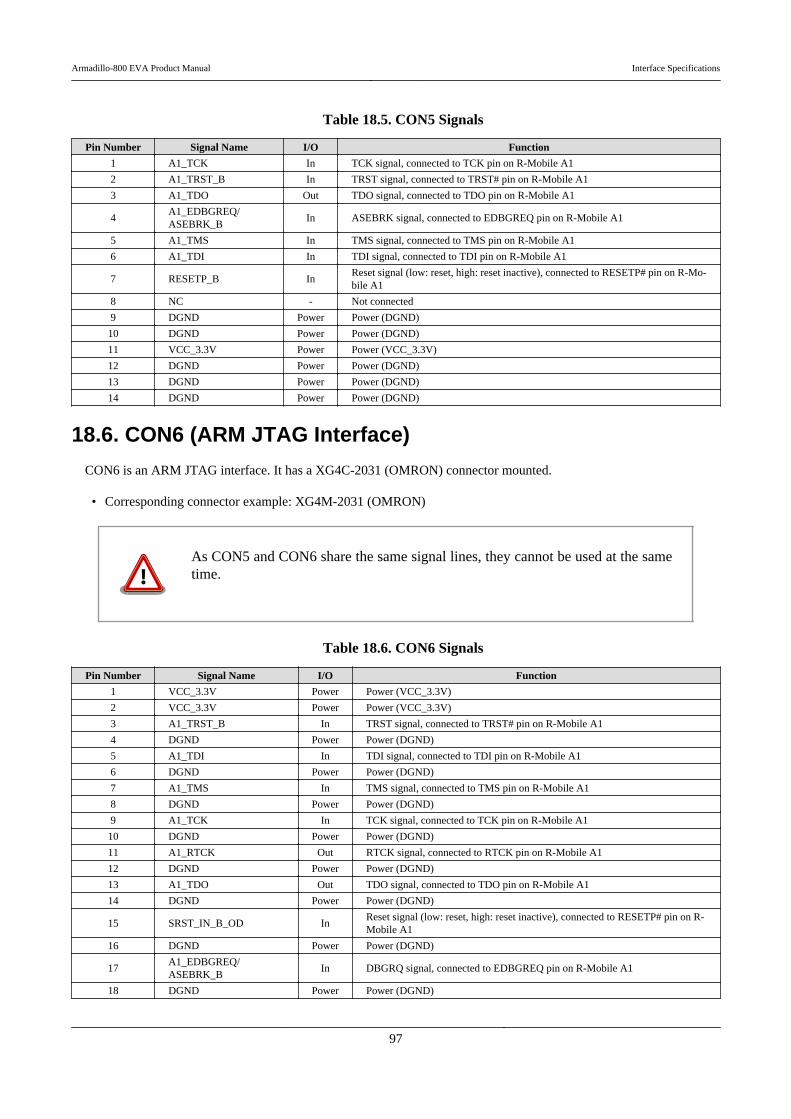
Table 18.5. CON5 Signals
Pin Number Signal Name I/O Function
1 A1_TCK In TCK signal, connected to TCK pin on R-Mobile A1
2 A1_TRST_B In TRST signal, connected to TRST# pin on R-Mobile A1
3 A1_TDO Out TDO signal, connected to TDO pin on R-Mobile A1
4A1_EDBGREQ/ASEBRK_B
In ASEBRK signal, connected to EDBGREQ pin on R-Mobile A1
5 A1_TMS In TMS signal, connected to TMS pin on R-Mobile A1
6 A1_TDI In TDI signal, connected to TDI pin on R-Mobile A1
7 RESETP_B InReset signal (low: reset, high: reset inactive), connected to RESETP# pin on R-Mo-bile A1
8 NC - Not connected
9 DGND Power Power (DGND)
10 DGND Power Power (DGND)
11 VCC_3.3V Power Power (VCC_3.3V)
12 DGND Power Power (DGND)
13 DGND Power Power (DGND)
14 DGND Power Power (DGND)
18.6. CON6 (ARM JTAG Interface)
CON6 is an ARM JTAG interface. It has a XG4C-2031 (OMRON) connector mounted.
• Corresponding connector example: XG4M-2031 (OMRON)
As CON5 and CON6 share the same signal lines, they cannot be used at the sametime.
Table 18.6. CON6 Signals
Pin Number Signal Name I/O Function
1 VCC_3.3V Power Power (VCC_3.3V)
2 VCC_3.3V Power Power (VCC_3.3V)
3 A1_TRST_B In TRST signal, connected to TRST# pin on R-Mobile A1
4 DGND Power Power (DGND)
5 A1_TDI In TDI signal, connected to TDI pin on R-Mobile A1
6 DGND Power Power (DGND)
7 A1_TMS In TMS signal, connected to TMS pin on R-Mobile A1
8 DGND Power Power (DGND)
9 A1_TCK In TCK signal, connected to TCK pin on R-Mobile A1
10 DGND Power Power (DGND)
11 A1_RTCK Out RTCK signal, connected to RTCK pin on R-Mobile A1
12 DGND Power Power (DGND)
13 A1_TDO Out TDO signal, connected to TDO pin on R-Mobile A1
14 DGND Power Power (DGND)
15 SRST_IN_B_OD InReset signal (low: reset, high: reset inactive), connected to RESETP# pin on R-Mobile A1
16 DGND Power Power (DGND)
17A1_EDBGREQ/ASEBRK_B
In DBGRQ signal, connected to EDBGREQ pin on R-Mobile A1
18 DGND Power Power (DGND)
Armadillo-800 EVA Product Manual Interface Specifications
97

Pin Number Signal Name I/O Function
19 NC - Connects to pin 17 on CON6 when resistor mounted at R45
20 DGND Power Power (DGND)
18.7. CON7 (SD Interface 1)CON7 is an SD slot.
Table 18.7. CON7 Signals
Pin Number Signal Name I/O Function
1 A1_SDHI0_D3 In/Out SD data (bit3), connected to SDHID3_0 pin on R-Mobile A1
2 A1_SDHI0_CMD In/Out SD command, connected to SDHICMD_0 pin on R-Mobile A1
3 DGND Power Power (DGND)
4 VCC_SD0 Power Power (VCC_SD0)
5 A1_SDHI0_CLK Out SD clock, connected to SDHICLK_0 pin on R-Mobile A1
6 DGND Power Power (DGND)
7 A1_SDHI0_D0 In/Out SD data (bit0), connected to SDHID0_0 pin on R-Mobile A1
8 A1_SDHI0_D1 In/Out SD data (bit1), connected to SDHID1_0 pin on R-Mobile A1
9 A1_SDHI0_D2 In/Out SD data (bit2), connected to SDHID2_0 pin on R-Mobile A1
10 A1_SDHI0_CD InSD card detect (low: card inserted, high: card removed), connected to D20 pin on R-MobileA1
11 FG Power Power (DGND)
12 A1_SDHI0_WP InWrite protect (low: writable, high: not writable), connected to SDHIWP_0 pin on R-Mo-bile A1
13 DGND Power Power (DGND)
14 DGND Power Power (DGND)
15 DGND Power Power (DGND)
18 DGND Power Power (DGND)
18.8. CON8 (SD Interface 2)CON8 is an SD slot.
As CON8 and CON14 share the same signal lines, they cannot be used at the sametime.
The selection of which interface the signals used with CON8 and CON14 are con-nected to is done with the DIP switch (SW1) SDHI1 configuration. For details,please refer to Table 4.3, “DIP Switch (SW1) Switch Functions” or Section 18.25,“SW1 (Function Selection Switch)”.
Table 18.8. CON8 Signals
Pin Number Signal Name I/O Function
1 SDSLOT2_SDHI1_D3 In/Out SD data (bit3), connected to MEMC_AD11 pin on R-Mobile A1
2 SDSLOT2_SDHI1_CMD In/Out SD command, connected to MEMC_CS0 pin on R-Mobile A1
3 DGND Power Power (DGND)
4 VCC_SD0 Power Power (VCC_SD0)
5 SDSLOT2_SDHI1_CLK In/Out SD clock, connected to MEMC_INT pin on R-Mobile A1
6 DGND Power Power (DGND)
7 SDSLOT2_SDHI1_D0 In/Out SD data (bit0), connected to MEMC_AD8 pin on R-Mobile A1
8 SDSLOT2_SDHI1_D1 In/Out SD data (bit1), connected to MEMC_AD9 pin on R-Mobile A1
Armadillo-800 EVA Product Manual Interface Specifications
98
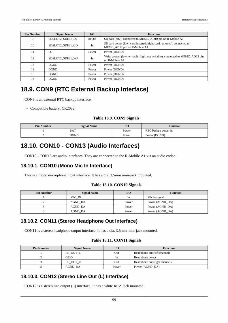
Pin Number Signal Name I/O Function
9 SDSLOT2_SDHI1_D2 In/Out SD data (bit2), connected to MEMC_AD10 pin on R-Mobile A1
10 SDSLOT2_SDHI1_CD InSD card detect (low: card inserted, high: card removed), connected toMEMC_AD12 pin on R-Mobile A1
11 FG Power Power (DGND)
12 SDSLOT2_SDHI1_WP InWrite protect (low: writable, high: not writable), connected to MEMC_AD13 pinon R-Mobile A1
13 DGND Power Power (DGND)
14 DGND Power Power (DGND)
15 DGND Power Power (DGND)
18 DGND Power Power (DGND)
18.9. CON9 (RTC External Backup Interface)
CON9 is an external RTC backup interface.
• Compatible battery: CR2032
Table 18.9. CON9 Signals
Pin Number Signal Name I/O Function
1 BAT Power RTC backup power in
2 DGND Power Power (DGND)
18.10. CON10 - CON13 (Audio Interfaces)
CON10 - CON13 are audio interfaces. They are connected to the R-Mobile A1 via an audio codec.
18.10.1. CON10 (Mono Mic In Interface)
This is a mono microphone input interface. It has a dia. 3.5mm mini-jack mounted.
Table 18.10. CON10 Signals
Pin Number Signal Name I/O Function
1 MIC_IN In Mic in signal
2 AGND_DA Power Power (AGND_DA)
3 AGND_DA Power Power (AGND_DA)
5 AGND_DA Power Power (AGND_DA)
18.10.2. CON11 (Stereo Headphone Out Interface)
CON11 is a stereo headphone output interface. It has a dia. 3.5mm mini-jack mounted.
Table 18.11. CON11 Signals
Pin Number Signal Name I/O Function
1 HP_OUT_L Out Headphone out (left channel)
2 GPIO In Headphone detect
3 HP_OUT_R Out Headphone out (right channel)
5 AGND_DA Power Power (AGND_DA)
18.10.3. CON12 (Stereo Line Out (L) Interface)
CON12 is a stereo line output (L) interface. It has a white RCA jack mounted.
Armadillo-800 EVA Product Manual Interface Specifications
99
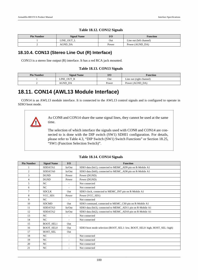
Table 18.12. CON12 Signals
Pin Number Signal Name I/O Function
1 LINE_OUT_L Out Line out (left channel)
2 AGND_DA Power Power (AGND_DA)
18.10.4. CON13 (Stereo Line Out (R) Interface)
CON13 is a stereo line output (R) interface. It has a red RCA jack mounted.
Table 18.13. CON13 Signals
Pin Number Signal Name I/O Function
1 LINE_OUT_R Out Line out (right channel)
2 AGND_DA Power Power (AGND_DA)
18.11. CON14 (AWL13 Module Interface)CON14 is an AWL13 module interface. It is connected to the AWL13 control signals and is configured to operate in
SDIO boot mode.
As CON8 and CON14 share the same signal lines, they cannot be used at the sametime.
The selection of which interface the signals used with CON8 and CON14 are con-nected to is done with the DIP switch (SW1) SDHI1 configuration. For details,please refer to Table 4.3, “DIP Switch (SW1) Switch Functions” or Section 18.25,“SW1 (Function Selection Switch)”.
Table 18.14. CON14 Signals
Pin Number Signal Name I/O Function
1 SDDATA1 In/Out SDIO data (bit1), connected to MEMC_AD9 pin on R-Mobile A1
2 SDDATA0 In/Out SDIO data (bit0), connected to MEMC_AD8 pin on R-Mobile A1
3 DGND Power Power (DGND)
4 DGND Power Power (DGND)
5 NC - Not connected
6 NC - Not connected
7 SDCLK Out SDIO clock, connected to MEMC_INT pin on R-Mobile A1
8 VCC_SD1 Power Power (VCC_SD1)
9 NC - Not connected
10 SDCMD Out SDIO command, connected to MEMC_CS0 pin on R-Mobile A1
11 SDDATA3 In/Out SDIO data (bit3), connected to MEMC_AD11 pin on R-Mobile A1
12 SDDATA2 In/Out SDIO data (bit2), connected to MEMC_AD10 pin on R-Mobile A1
13 NC - Not connected
14 NC - Not connected
15 BOOT_SEL1 Out
SDIO boot mode selection (BOOT_SEL1: low, BOOT_SEL0: high, HOST_SEL: high)16 BOOT_SEL0 Out
17 HOST_SEL Out
18 NC - Not connected
19 NC - Not connected
20 NC - Not connected
21 NC - Not connected
Armadillo-800 EVA Product Manual Interface Specifications
100

Pin Number Signal Name I/O Function
22 NC - Not connected
23 NC - Not connected
24 NC - Not connected
25 NC - Not connected
26 NC - Not connected
27 NC - Not connected
28 HRST In Connected to VCC_SD1
29 NC - Not connected
30 NC - Not connected
31 NC - Not connected
32 NC - Not connected
33 NC - Not connected
34 NC - Not connected
18.12. CON15 (Expansion Interface)
CON15 is an expansion interface. A connector is not mounted.
• Board side connector example: XG4C-6031 (OMRON)• Corresponding connector example: XG4M-6031 (OMRON)
Table 18.15. CON15 Signals
Pin Number Signal Name I/O Function
1 VCC_5V Power Power (VCC_5V)
2 VCC_5V Power Power (VCC_5V)
3 VCC_3.3V Power Power (VCC_3.3V)
4 VCC_3.3V Power Power (VCC_3.3V)
5 DGND Power Power (DGND)
6 DGND Power Power (DGND)
7 A1_VIO0_CKO In/Out Connected to VIO_CKO_0 pin on R-Mobile A1
8 A1_VIO0_CLK In/Out Connected to VIO_CLK_0 pin on R-Mobile A1
9 A1_VIO0_HD In/Out Connected to VIO_HD_0 pin on R-Mobile A1
10 A1_VIO0_VD In/Out Connected to VIO_VD_0 pin on R-Mobile A1
11 A1_VIO0_FIELD In/Out Connected to VIO_FIELD_0 pin on R-Mobile A1
12 A1_VIO0_D0 In/Out Connected to VIO_D0_0 pin on R-Mobile A1
13 A1_VIO0_D1 In/Out Connected to VIO_D1_0 pin on R-Mobile A1
14 A1_VIO0_D2 In/Out Connected to VIO_D2_0 pin on R-Mobile A1
15 A1_VIO0_D3 In/Out Connected to VIO_D3_0 pin on R-Mobile A1
16 A1_VIO0_D4 In/Out Connected to VIO_D4_0 pin on R-Mobile A1
17 A1_VIO0_D5 In/Out Connected to VIO_D5_0 pin on R-Mobile A1
18 A1_VIO0_D6 In/Out Connected to VIO_D6_0 pin on R-Mobile A1
19 A1_VIO0_D7 In/Out Connected to VIO_D7_0 pin on R-Mobile A1
20 A1_VIO0_STANDBY In/Out Connected to D22 pin on R-Mobile A1
21 A1_VIO0_RST_B In/Out Connected to D23 pin on R-Mobile A1
22 DGND Power Power (DGND)
23 A1_VIO1_CLK In/Out Connected to SCIFA_RXD_0 pin on R-Mobile A1
24 A1_VIO1_HD In/Out Connected to D29 pin on R-Mobile A1
25 A1_VIO1_VD In/Out Connected to SCIFA_TXD_0 pin on R-Mobile A1
26 A1_VIO1_D0 In/Out Connected to VIO_D8_0 pin on R-Mobile A1
27 A1_VIO1_D1 In/Out Connected to VIO_D9_0 pin on R-Mobile A1
28 A1_VIO1_D2 In/Out Connected to VIO_D10_0 pin on R-Mobile A1
29 A1_VIO1_D3 In/Out Connected to VIO_D11_0 pin on R-Mobile A1
30 A1_VIO1_D4 In/Out Connected to VIO_D12_0 pin on R-Mobile A1
Armadillo-800 EVA Product Manual Interface Specifications
101

Pin Number Signal Name I/O Function
31 A1_VIO1_D5 In/Out Connected to VIO_D13_0 pin on R-Mobile A1
32 A1_VIO1_D6 In/Out Connected to VIO_D14_0 pin on R-Mobile A1
33 A1_VIO1_D7 In/Out Connected to VIO_D15_0 pin on R-Mobile A1
34 A1_VIO1_STANDBY In/Out Connected to SCIFA_RTS_0# pin on R-Mobile A1
35 A1_VIO1_RST_B In/Out Connected to SCIFA_CTS_0# pin on R-Mobile A1
36 CAM_DISABLE In Camera enable / disable switch signal (low: enable, high: disable)
37 VCC_3.3V Power Power (VCC_3.3V)
38 DGND Power Power (DNGD)
39 A1_STP0_IPCLK In/Out Connected to STP_IPCLK_0 pin on R-Mobile A1
40 A1_STP0_IPSYNC In/Out Connected to SCIFB_TXD pin on R-Mobile A1
41 A1_STP0_IPEN In/Out Connected to SCIFB_RXD pin on R-Mobile A1
42 A1_STP0_IPD0 In/Out Connected to SCIFB_SCK pin on R-Mobile A1
43 A1_STP0_IPD1 In/Out Connected to MEMC_AD1 pin on R-Mobile A1
44 A1_STP0_IPD2 In/Out Connected to SCIFA_RTS_1# pin on R-Mobile A1
45 A1_STP0_IPD3 In/Out Connected to MEMC_AD2 pin on R-Mobile A1
46 A1_STP0_IPD4 In/Out Connected to MEMC_AD3 pin on R-Mobile A1
47 A1_STP0_IPD5 In/Out Connected to SCIFA_CTS_1# pin on R-Mobile A1
48 A1_STP0_IPD6 In/Out Connected to MEMC_WAIT pin on R-Mobile A1
49 A1_STP0_IPD7 In/Out Connected to MEMC_NOE pin on R-Mobile A1
50 A1_SIM_D In/Out Connected to SCIFA_SCK_2 pin on R-Mobile A1
51 A1_SIM_CLK In/Out Connected to MEMC_ADV pin on R-Mobile A1
52 A1_SIM_RST In/Out Connected to MEMC_CS1 pin on R-Mobile A1
53 A1_PORT15 In/Out Connected to FMSOIBT pin on R-Mobile A1
54 A1_PORT14 In/Out Connected to FMSOILR pin on R-Mobile A1
55 RESETP_B In/Out Connected to RESETP# pin on R-Mobile A1
56 NC - Not connected
57 VCC_3.3V Power Power (VCC_3.3V)
58 DGND Power Power (DGND)
59 A1_SCL In/Out Connected to I2C_SCL_0 pin on R-Mobile A1
60 A1_SDA In/Out Connected to I2C_SDA_0 pin on R-Mobile A1
18.13. CON16 (LCD Interface 1)
CON16 is an LCD interface. A connector is not mounted.
As CON16 and CON17 share the same signal lines, they cannot be used at the sametime.
• Board side connector example: XG4C-5031 (OMRON)• Corresponding connector example: XG4M-5031 (OMRON)
Table 18.16. CON16 Signals
Pin Number Signal Name I/O Function
1 VCC_5V Power Power (VCC_5V)
2 VCC_5V Power Power (VCC_5V)
3 VCC_3.3V Power Power (VCC_3.3V)
4 VCC_3.3V Power Power (VCC_3.3V)
5 DGND Power Power (DGND)
6 DGND Power Power (DGND)
Armadillo-800 EVA Product Manual Interface Specifications
102
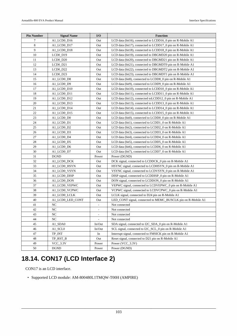
Pin Number Signal Name I/O Function
7 A1_LCD0_D16 Out LCD data (bit16), connected to LCDD16_0 pin on R-Mobile A1
8 A1_LCD0_D17 Out LCD data (bit17), connected to LCDD17_0 pin on R-Mobile A1
9 A1_LCD0_D18 Out LCD data (bit18), connected to LCDD18_0 pin on R-Mobile A1
10 LCD0_D19 Out LCD data (bit19), connected to DBGMD20 pin on R-Mobile A1
11 LCD0_D20 Out LCD data (bit20), connected to DBGMD21 pin on R-Mobile A1
12 LCD0_D21 Out LCD data (bit21), connected to DBGMDT0 pin on R-Mobile A1
13 LCD0_D22 Out LCD data (bit22), connected to DBGMDT2 pin on R-Mobile A1
14 LCD0_D23 Out LCD data (bit23), connected to DBGMDT1 pin on R-Mobile A1
15 A1_LCD0_D8 Out LCD data (bit8), connected to LCDD8_0 pin on R-Mobile A1
16 A1_LCD0_D9 Out LCD data (bit9), connected to LCDD9_0 pin on R-Mobile A1
17 A1_LCD0_D10 Out LCD data (bit10), connected to LCDD10_0 pin on R-Mobile A1
18 A1_LCD0_D11 Out LCD data (bit11), connected to LCDD11_0 pin on R-Mobile A1
19 A1_LCD0_D12 Out LCD data (bit12), connected toLCDD12_0 pin on R-Mobile A1
20 A1_LCD0_D13 Out LCD data (bit13), connected to LCDD13_0 pin on R-Mobile A1
21 A1_LCD0_D14 Out LCD data (bit14), connected to LCDD14_0 pin on R-Mobile A1
22 A1_LCD0_D15 Out LCD data (bit15), connected to LCDD15_0 pin on R-Mobile A1
23 A1_LCD0_D0 Out LCD data (bit0), connected to LCDD0_0 pin on R-Mobile A1
24 A1_LCD0_D1 Out LCD data (bit1), connected to LCDD1_0 on R-Mobile A1
25 A1_LCD0_D2 Out LCD data (bit2), connected to LCDD2_0 on R-Mobile A1
26 A1_LCD0_D3 Out LCD data (bit3), connected to LCDD3_0 on R-Mobile A1
27 A1_LCD0_D4 Out LCD data (bit4), connected to LCDD4_0 on R-Mobile A1
28 A1_LCD0_D5 Out LCD data (bit5), connected to LCDD5_0 on R-Mobile A1
29 A1_LCD0_D6 Out LCD data (bit6), connected to LCDD6_0 on R-Mobile A1
30 A1_LCD0_D7 Out LCD data (bit7), connected to LCDD7_0 on R-Mobile A1
31 DGND Power Power (DGND)
32 A1_LCD0_DCK Out DCK signal, connected to LCDDCK_0 pin on R-Mobile A1
33 A1_LCD0_HSYN Out HSYNC signal, connected to LCDHSYN_0 pin on R-Mobile A1
34 A1_LCD0_VSYN Out VSYNC signal, connected to LCDVSYN_0 pin on R-Mobile A1
35 A1_LCD0_DISP Out DISP signal, connected to LCDDISP_0 pin on R-Mobile A1
36 A1_LCD0_DON Out DON signal, connected to LCDDON_0 pin on R-Mobile A1
37 A1_LCD0_VEPWC Out VEPWC signal, connected to LCDVEPWC_0 pin on R-Mobile A1
38 A1_LCD0_VCPWC Out VCPWC signal, connected to LCDVCPWC_0 pin on R-Mobile A1
39 A1_LCD0_LCLK Out LCLK signal, connected to D24 pin on R-Mobile A1
40 A1_LCD0_LED_CONT Out LED_CONT signal, connected to MEMC_BUSCLK pin on R-Mobile A1
41 NC - Not connected
42 NC - Not connected
43 NC - Not connected
44 NC - Not connected
45 A1_SDA0 In/Out SDA signal, connected to I2C_SDA_0 pin on R-Mobile A1
46 A1_SCL0 In/Out SCL signal, connected to I2C_SCL_0 pin on R-Mobile A1
47 TP_INT In Interrupt signal, connected to FMSICK pin on R-Mobile A1
48 TP_RST_B Out Reset signal, connected to D21 pin on R-Mobile A1
49 VCC_3.3V Power Power (VCC_3.3V)
50 DGND Power Power (DGND)
18.14. CON17 (LCD Interface 2)CON17 is an LCD interface.
• Supported LCD module: AM-800480L1TMQW-T00H (AMPIRE)
Armadillo-800 EVA Product Manual Interface Specifications
103
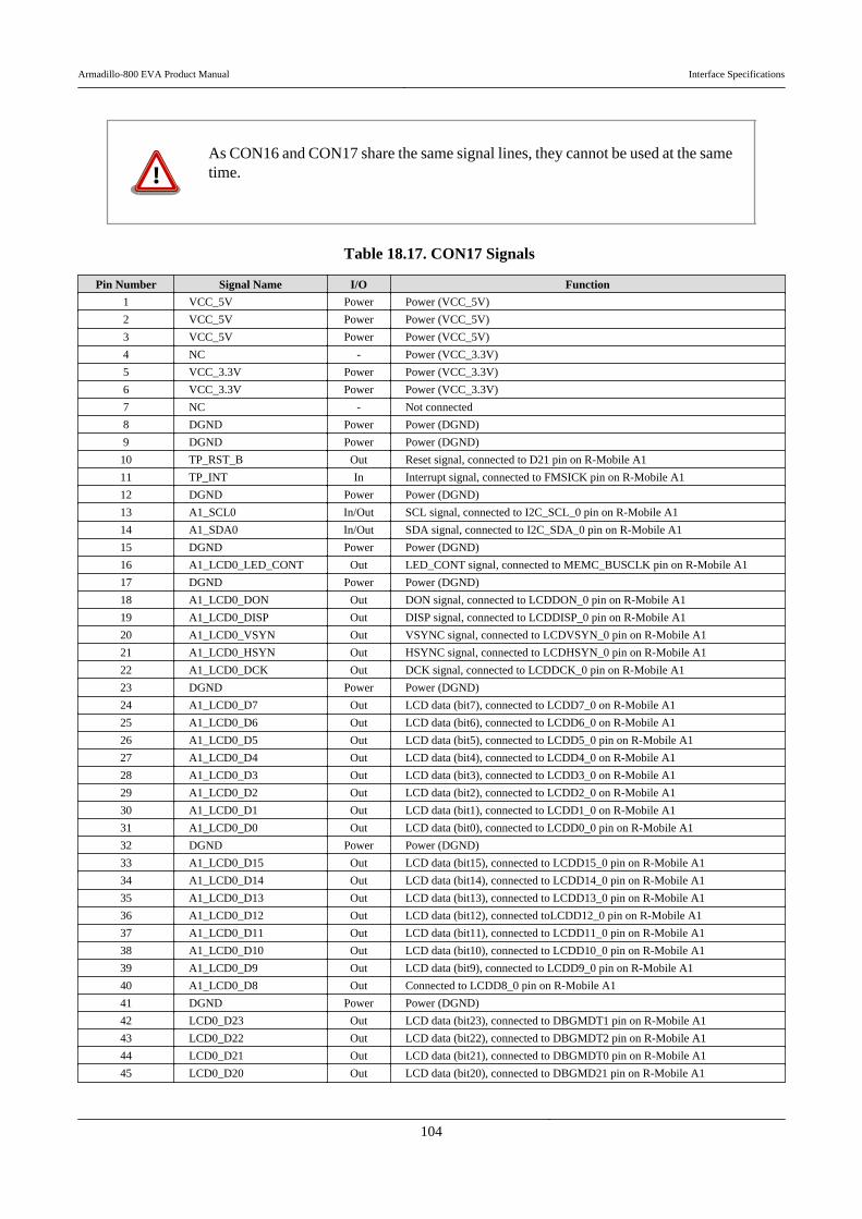
As CON16 and CON17 share the same signal lines, they cannot be used at the sametime.
Table 18.17. CON17 Signals
Pin Number Signal Name I/O Function
1 VCC_5V Power Power (VCC_5V)
2 VCC_5V Power Power (VCC_5V)
3 VCC_5V Power Power (VCC_5V)
4 NC - Power (VCC_3.3V)
5 VCC_3.3V Power Power (VCC_3.3V)
6 VCC_3.3V Power Power (VCC_3.3V)
7 NC - Not connected
8 DGND Power Power (DGND)
9 DGND Power Power (DGND)
10 TP_RST_B Out Reset signal, connected to D21 pin on R-Mobile A1
11 TP_INT In Interrupt signal, connected to FMSICK pin on R-Mobile A1
12 DGND Power Power (DGND)
13 A1_SCL0 In/Out SCL signal, connected to I2C_SCL_0 pin on R-Mobile A1
14 A1_SDA0 In/Out SDA signal, connected to I2C_SDA_0 pin on R-Mobile A1
15 DGND Power Power (DGND)
16 A1_LCD0_LED_CONT Out LED_CONT signal, connected to MEMC_BUSCLK pin on R-Mobile A1
17 DGND Power Power (DGND)
18 A1_LCD0_DON Out DON signal, connected to LCDDON_0 pin on R-Mobile A1
19 A1_LCD0_DISP Out DISP signal, connected to LCDDISP_0 pin on R-Mobile A1
20 A1_LCD0_VSYN Out VSYNC signal, connected to LCDVSYN_0 pin on R-Mobile A1
21 A1_LCD0_HSYN Out HSYNC signal, connected to LCDHSYN_0 pin on R-Mobile A1
22 A1_LCD0_DCK Out DCK signal, connected to LCDDCK_0 pin on R-Mobile A1
23 DGND Power Power (DGND)
24 A1_LCD0_D7 Out LCD data (bit7), connected to LCDD7_0 on R-Mobile A1
25 A1_LCD0_D6 Out LCD data (bit6), connected to LCDD6_0 on R-Mobile A1
26 A1_LCD0_D5 Out LCD data (bit5), connected to LCDD5_0 pin on R-Mobile A1
27 A1_LCD0_D4 Out LCD data (bit4), connected to LCDD4_0 on R-Mobile A1
28 A1_LCD0_D3 Out LCD data (bit3), connected to LCDD3_0 on R-Mobile A1
29 A1_LCD0_D2 Out LCD data (bit2), connected to LCDD2_0 on R-Mobile A1
30 A1_LCD0_D1 Out LCD data (bit1), connected to LCDD1_0 on R-Mobile A1
31 A1_LCD0_D0 Out LCD data (bit0), connected to LCDD0_0 pin on R-Mobile A1
32 DGND Power Power (DGND)
33 A1_LCD0_D15 Out LCD data (bit15), connected to LCDD15_0 pin on R-Mobile A1
34 A1_LCD0_D14 Out LCD data (bit14), connected to LCDD14_0 pin on R-Mobile A1
35 A1_LCD0_D13 Out LCD data (bit13), connected to LCDD13_0 pin on R-Mobile A1
36 A1_LCD0_D12 Out LCD data (bit12), connected toLCDD12_0 pin on R-Mobile A1
37 A1_LCD0_D11 Out LCD data (bit11), connected to LCDD11_0 pin on R-Mobile A1
38 A1_LCD0_D10 Out LCD data (bit10), connected to LCDD10_0 pin on R-Mobile A1
39 A1_LCD0_D9 Out LCD data (bit9), connected to LCDD9_0 pin on R-Mobile A1
40 A1_LCD0_D8 Out Connected to LCDD8_0 pin on R-Mobile A1
41 DGND Power Power (DGND)
42 LCD0_D23 Out LCD data (bit23), connected to DBGMDT1 pin on R-Mobile A1
43 LCD0_D22 Out LCD data (bit22), connected to DBGMDT2 pin on R-Mobile A1
44 LCD0_D21 Out LCD data (bit21), connected to DBGMDT0 pin on R-Mobile A1
45 LCD0_D20 Out LCD data (bit20), connected to DBGMD21 pin on R-Mobile A1
Armadillo-800 EVA Product Manual Interface Specifications
104
Pin Number Signal Name I/O Function
46 LCD0_D19 Out LCD data (bit19), connected to DBGMD20 pin on R-Mobile A1
47 A1_LCD0_D18 Out LCD data (bit18), connected to LCDD18_0 pin on R-Mobile A1
48 A1_LCD0_D17 Out LCD data (bit17), connected to LCDD17_0 pin on R-Mobile A1
49 A1_LCD0_D16 Out LCD data (bit16), connected to LCDD16_0 pin on R-Mobile A1
50 DGND Power Power (DGND)
18.15. CON19 (Power In Interface)
CON19 is a DC jack for power supply. The AC adapter jack shape is EIAJ RC-5320A (voltage classification 2) compliant.
Figure 18.1. AC Adapter Polarity Mark
Table 18.18. CON19 Signals
Pin Number Signal Name I/O Function
1 VCC_5V Power Power (VCC_5V)
2 DGND Power Power (DGND)
3 DGND Power Power (DGND)
4 DGND Power Power (DGND)
18.16. CON20 (USB Interface 1)
CON20 is a USB host interface. It has a Type A connector mounted.
As CON20 and CON24 share the same signal lines, they cannot be used at the sametime.
The selection of which interface the signals used with CON20 and CON24 areconnected to is done with the DIP switch (SW1) USB0 configuration. For details,please refer to Table 4.3, “DIP Switch (SW1) Switch Functions” or Section 18.25,“SW1 (Function Selection Switch)”.
Table 18.19. CON20 Signals
Pin Number Signal Name I/O Function
1 VCC_5V Power Power (VCC_5V)
2 A1_DM0 In/Out USB minus side signal, connected to DM_0 pin on R-Mobile A1
3 A1_DP0 In/Out USB plus side signal, connected to DP_0 pin on R-Mobile A1
4 DGND Power Power (DGND)
5 DGND Power Power (DGND)
6 DGND Power Power (DGND)
7 DGND Power Power (DGND)
18.17. CON21 (USB Interface 2)
This is a USB host interface. It has a Type A connector mounted.
Armadillo-800 EVA Product Manual Interface Specifications
105

Table 18.20. CON21 Signals
Pin Number Signal Name I/O Function
1 VCC_5V Power Power (VCC_5V)
2 A1_DM1 In/Out USB minus side signal, connected to DM_1 pin on R-Mobile A1
3 A1_DP1 In/Out USB plus side signal, connected to DP_1 pin on R-Mobile A1
4 DGND Power Power (DGND)
5 DGND Power Power (DGND)
6 DGND Power Power (DGND)
7 DGND Power Power (DGND)
18.18. CON22 (Serial Interface)This is an asynchronous (start-stop synchronization) serial interface. It has a D-Sub 9-pin mounted. It is connected to the
R-Mobile A1 via a RS232C transceiver.
Table 18.21. CON22 Signals
Pin Number Signal Name I/O Function
1 NC - Not connected
2 UART_RXD In UART received data
3 UART_TXD Out UART transmitted data
4 NC - Not connected
5 DGND Power Power (DGND)
6 RTS Out Always high
7 CTS - Not connected
8 NC - Not connected
9 NC - Not connected
18.19. CON23 (LAN Interface)This is a 10BASE-T/100BASE-TX LAN interface. It has a RJ45 connector mounted. It is connected to the R-Mobile A1
via an Ethernet PHY.
Table 18.22. CON23 Signals
Pin Number Signal Name I/O Function
1 TX+ Out Differential twisted-pair transmit output (+)
2 TX- Out Differential twisted-pair transmit output (-)
3 RX+ In Differential twisted-pair receive input (+)
4 - - 75 ohm termination, internal connector connection to CON23 (5 pin)
5 - - 75 ohm termination, internal connector connection to CON23 (4 pin)
6 RX- In Differential twisted-pair receive input (-)
7 - - 75 ohm termination, internal connector connection to CON23 (8 pin)
8 - - 75 ohm termination, internal connector connection to CON23 (7 pin)
18.20. CON24 (USB Interface 3)CON24 is a USB device interface. It has a Type B connector mounted.
As CON20 and CON24 share the same signal lines, they cannot be used at the sametime.
The selection of which interface the signals used with CON20 and CON24 areconnected to is done with the DIP switch (SW1) USB0 configuration. For details,
Armadillo-800 EVA Product Manual Interface Specifications
106
please refer to Table 4.3, “DIP Switch (SW1) Switch Functions” or Section 18.25,“SW1 (Function Selection Switch)”.
Table 18.23. CON24 Signals
Pin Number Signal Name I/O Function
1 A1_VBUS Power Power (A1_VBUS), connected to VBUS pin on R-Mobile A1
2 A1_DM0 In/Out USB minus side signal, connected to DM_0 pin on R-Mobile A1
3 A1_DP0 In/Out USB plus side signal, connected to DP_0 pin on R-Mobile A1
4 DGND Power Power (DGND)
5 FG Power Power (DGND)
6 FG Power Power (DGND)
7 FG Power Power (DGND)
18.21. LED1 (Camera LED)
LED1 is a flash LED for the camera module.
Table 18.24. LED1 Behavior
LED Name (Color) Explanation
LED1 LED (yellow)Connected to GPIO4_FLASH on the camera module
(low: off, high: on)
18.22. LED2 (Power LED)
LED2 is the power LED. It is active when VCC_3.3V is being supplied.
Table 18.25. LED Behavior
LED Name (Color) On Off
LED2 Power LED (green) Shows that VCC_3.3V is being supplied. Shows that VCC_3.3V is not being supplied.
18.23. LED3 - LED6 (User LEDs)
LED3 - LED6 are user LEDs.
Table 18.26. LED3 - LED6 Behavior
LED Name (Color) Explanation
LED3 User LED (yellow) Connected to FRB pin on R-Mobile A1 (low: off, high: on)
LED4 User LED (yellow) Connected to CS4# pin on R-Mobile A1 (low: off, high: on)
LED5 User LED (yellow) Connected to CS2# pin on R-Mobile A1 (low: off, high: on)
LED6 User LED (yellow) Connected to WAIT# pin on R-Mobile A1 (low: off, high: on)
18.24. LED7, LED8 (LAN LEDs)
LED7 and LED8 are the status LEDs of the LAN interface (CON23).
Table 18.27. LED7, LED8 Behavior
LED Name (Color) On Off Blinking
LED7LINK/ACT LED(green)
LAN cable connected and linkestablished.
LAN cable connected, link not established.Sending and re-ceiving data.
Armadillo-800 EVA Product Manual Interface Specifications
107

LED Name (Color) On Off Blinking
LED8SPEED LED (Yel-low)
100BASE-TX link established.10BASE-T link established if LAN cable con-nected. Otherwise link not established.
-
18.25. SW1 (Function Selection Switch)SW1 is an eight point DIP switch. Each signal is high when the connected switch is off and low when the switch is on.
Table 18.28. SW1 Signals
Pin Number Signal Name Function
1 A1_PORT101_JP2 Connected to FCE0# pin on R-Mobile A1
2 A1_MD2 Connected to MD2 pin on R-Mobile A1
3 A1_MD3 Connected to MD3 pin on R-Mobile A1
4 MMC_DISABLEeMMC and Expansion Bus Interface (CON2) switch
(on: eMMC, off: Expansion Bus Interface)
5 SDSLOT2_ENABLESD Interface 2 (CON8) and AWL13 Module (CON14) switch
(on: SD Interface 2, off: AWL13 Module)
6 USB_DEVICE_MODEUSB Device Interface (CON24) and USB Host Interface (CON20) switch
(on: USB Device Interface, off: USB Host Interface)
7 DBGMD20 Connected to DBGMD20 pin on R-Mobile A1
8 DBGMD21 Connected to DBGMD21 pin on R-Mobile A1
18.26. SW2 (Reset Switch)SW2 is a reset switch. It has a tact switch mounted. It is connected to the reset IC on the board.
Figure 18.2. Reset Block Diagram
Table 18.29. SW2 Function
SW Function
SW2 Reset (pushed: reset, released: not reset)
18.27. SW3 - SW6 (User Switches)SW3 - SW6 are user switches. They have tact switches mounted. Each pin is low when the connected switch is pushed,
and high when the switch is released.
Table 18.30. SW3 - SW6 Functions
SW Explanation
SW3 Connected to MEMC_AD6 pin on R-Mobile A1
SW4 Connected to MEMC_AD7 pin on R-Mobile A1
SW5 Connected to MEMC_AD4 pin on R-Mobile A1
Armadillo-800 EVA Product Manual Interface Specifications
108

SW Explanation
SW6 Connected to MEMC_AD5 pin on R-Mobile A1
Armadillo-800 EVA Product Manual Interface Specifications
109
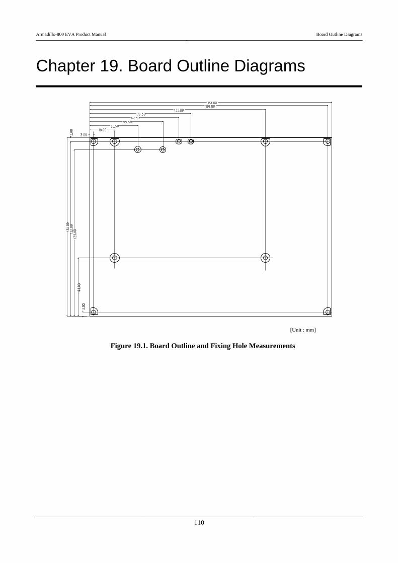
Chapter 19. Board Outline Diagrams
[Unit : mm]
Figure 19.1. Board Outline and Fixing Hole Measurements
Armadillo-800 EVA Product Manual Board Outline Diagrams
110

[Unit : mm]
Figure 19.2. Connector Center Measurements
Armadillo-800 EVA Product Manual Board Outline Diagrams
111

Appendix A. Hermit-At Bootloader
Hermit-At is a functional downloader and bootloader[1] used on Atmark Techno products. The Hermit-At bootloaderprompt is displayed when an Armadillo board is booted in maintenance mode. From the prompt it is possible to entercommands for a variety of operations such as updating flash memory and setting Linux kernel parameters. The followinggives details on the most well used functions.
Hermit-At Modes
Hermit-AT has two modes: the "interactive mode" which displays the commandprompt and operates interactively, and the "batch mode" for communicating withthe Hermit-AT downloader. The command prompt and entered characters are notdisplayed in batch mode, but commands can be executed.
Hermit-AT is always in interactive mode after booting. To move from interactivemode to batch mode enter a tilde "~" and to move from batch mode to interactivemode enter an exclamation mark "!".
Hermit-AT moves to batch mode when communicating with the Hermit-ATdownloader. This is because the Hermit-AT downloader sends a tilde in order toestablish the communication.
When moving from interactive mode to batch mode and when an entered com-mand succeeds in batch mode the following is displayed.
+OK
A.1. version
This command displays version information.
[1]Only the Hermit-At bootloader functionality can be used with Armadillo-800 EVA.
Armadillo-800 EVA Product Manual Hermit-At Bootloader
112

Syntax: version
Figure A.1. version Syntax
A.1.1. version Example
hermit> versionHermit-At v3.0.0 (Armadillo-800 EVA) compiled at 22:22:10, Dec 21 2011
Figure A.2. version Example
A.2. info
This command displays board information.
Syntax: info
Figure A.3. info Syntax
A.2.1. info Example
hermit> info Board Type: 0x08000000 Revision: 0x00000003 Lot: 0x00000001Serial Number: 0 Boot Mode: 0x00000038 (eMMC) Jumper: ON Tact-SW: OFF,OFF,OFF,OFF ORIG MAC-1: 00:11:0c:00:00:00
Figure A.4. info Example
A.3. mac
This command displays the MAC address.
Syntax: mac
Figure A.5. mac Syntax
Armadillo-800 EVA Product Manual Hermit-At Bootloader
113
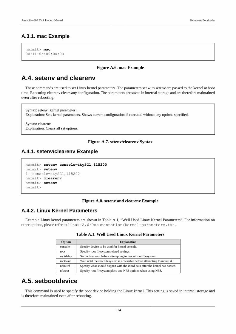
A.3.1. mac Example
hermit> mac00:11:0c:00:00:00
Figure A.6. mac Example
A.4. setenv and clearenvThese commands are used to set Linux kernel parameters. The parameters set with setenv are passed to the kernel at boot
time. Executing clearenv clears any configuration. The parameters are saved in internal storage and are therefore maintainedeven after rebooting.
Syntax: setenv [kernel parameter]...Explanation: Sets kernel parameters. Shows current configuration if executed without any options specified.
Syntax: clearenvExplanation: Clears all set options.
Figure A.7. setenv/clearenv Syntax
A.4.1. setenv/clearenv Example
hermit> setenv console=ttySC1,115200hermit> setenv1: console=ttySC1,115200hermit> clearenvhermit> setenvhermit>
Figure A.8. setenv and clearenv Example
A.4.2. Linux Kernel Parameters
Example Linux kernel parameters are shown in Table A.1, “Well Used Linux Kernel Parameters”. For information onother options, please refer to linux-2.6/Documentation/kernel-parameters.txt.
Table A.1. Well Used Linux Kernel Parameters
Option Explanation
console Specify device to be used for kernel console.
root Specify root filesystem related settings.
rootdelay Seconds to wait before attempting to mount root filesystem.
rootwait Wait until the root filesystem is accessible before attempting to mount it.
noinitrd Specify what should happen with the initrd data after the kernel has booted.
nfsroot Specify root filesystem place and NFS options when using NFS.
A.5. setbootdeviceThis command is used to specify the boot device holding the Linux kernel. This setting is saved in internal storage and
is therefore maintained even after rebooting.
Armadillo-800 EVA Product Manual Hermit-At Bootloader
114

Syntax: setbootdevice mmcblk0pNExplanation: Extract the kernel image stored in the /boot/ directory on partition N of the internal storage to RAM and boot it
Syntax: setbootdevice mmcblk1pNExplanation: Extract the kernel image stored in the /boot/ directory on partition N of an SD card (CON7) to RAM and boot ⏎it
Figure A.9. setbootdevice Syntax
A.5.1. setbootdevice Example
To boot the kernel image stored in the /boot/ directory on partition 4 of the internal storage, execute the command shownin Figure A.10, “Assigning Partition 4 of Internal Storage as Boot Device”.
hermit> setbootdevice mmcblk0p4
Figure A.10. Assigning Partition 4 of Internal Storage as Boot Device
To boot the kernel image stored on partition 1 of an SD card (CON7), execute the command shown in Figure A.11,“Assigning SD Card as Boot Device”.
hermit> setbootdevice mmcblk1p1
Figure A.11. Assigning SD Card as Boot Device
A.6. frob
This command is used to enter a mode for reading or altering data at a specified address.
Table A.2. frob Command
frob Command Explanation
peek [addr] Read 32bit data from specified address
peek16 [addr] Read 16bit data from specified address
peek8 [addr] Read 8bit data from specified address
poke [addr] [value] Write 32bit data to specified address
poke16 [addr] [value] Write 16bit data to specified address
poke8 [addr] [value] Write 8bit data to specified address
A.7. boot
This command boots the Linux kernel image from the boot device specified with the setbootdevice command.
Syntax: boot
Figure A.12. boot Syntax
Armadillo-800 EVA Product Manual Hermit-At Bootloader
115

A.7.1. boot Example
hermit> bootmmcsd: SD card at address 0x00000001mmcsd: M8G2FA 1048576KiBgendisk: /dev/mmcblk0p4: start=0x000f4280, size=0x001dcdc0gendisk: Image.bin is found. (4390496 Bytes)
Copying kernel...done. Doing console=ttySC1,115200Doing noinitrdDoing rootwaitDoing root=/dev/mmcblk0p4
Doing init=/init Linux version 2.6.35.7 (atmark@atde4) (gcc version 4.4.5 (Debian 4.4.5-8) )
#1 PREEMPT Wed Dec 21 22:37:47 JST 2011 CPU: ARMv7 Processor [412fc093] revision 3 (ARMv7), cr=10c53c7fCPU: VIPT nonaliasing data cache, VIPT nonaliasing instruction cacheMachine: Armadillo-800EVA : :
Figure A.13. boot Example
The kernel image is extracted to RAM.
Kernel parameters set with the setenv command are displayed. All messages up to this point are from Hermit-At.
The kernel is booted and kernel boot log displayed.
Armadillo-800 EVA Product Manual Hermit-At Bootloader
116

Revision History
Revision Data Description
1.0.0 01/05/2012 • Initial Release
1.1.0 Feb. 02, 2012 • Made updates for linux-2.6.35-a800eva-at2• Moved all function use descriptions to Chapter 8, Function Use with De-
bian GNU/Linux• Added use descriptions for devices that connect to CON3/12/13, external
storage devices, the LED backlight, LEDs and user switches to Chapter 8,Function Use with Debian GNU/Linux.
• Moved all explanations of the Linux kernel to Chapter 17, Linux KernelSpecifications
• Added explanations of the default configuration and Android functions toChapter 17, Linux Kernel Specifications
• Updated the explanation in Section 1.2, “Document Structure”• Added a note on connecting the AC adapter• Table 18.3, “CON3 Signals” Changed DDC_CEC signal to Non-connec-
ted.• Corrected various errors and inconsistencies
Armadillo-800 EVA Product Manual Product Manual

Armadillo-800 EVA Product ManualVersion 1.1.02012/02/28
Atmark Techno, Inc.060-0035 AFT Bldg., N5E2, Chuo-ku, Sapporo TEL 011-207-6550 FAX 011-207-6570