Embed Size (px)
Citation preview

ARTIFICIAL INTELLIGENCE - 2012
Jiří BÍLA
A
MA
TIC
KÉ
ŘÍ A INŽENÝ
Á IN
FO
RM
A
Ústav přístrojové a řídicí techniky, Fakulta strojní, ČVUT v PrazeTechnická 4 , 166 07 Praha 6 , Tel: 00420 2 2435 2563 , Fax: 00420 2 3116414

Main items of the lecture
1. Artificial Intelligence - State of Art
2. Control of Complex Systems.
3. Pattern Recognition - Computer Vision.
4. Computer Aided ... (CAD, CAPP, CAM, CAQC, ..)
5. HMI - Human Machine Interface
6. Problem Solving.
7. Autonomous systems (planetary modules).

I. AI - BEGINNING AND EVOLUTION
Motivation and Objectives
Consequences of Cybernetics, Control Theory and Automation „Stabilization of quantities (e.g., stabilization of temperature in this building on
23C)“
„Stabilization of O2 concentration (in atmosphere)“ ?? …
Understanding to speech, text and patterns „Communication in a natural language.“
„How a robot goes out from a closed kitchen ?“
„How to design a „for ever winning“chess automaton ?“
Modeling of coordination structures (e.g., function of living ecosystems, function of the brain, modeling of the Mind ).
Unsolvable problems. E.g., „The method of stabilization of salt concentration in oceans“.
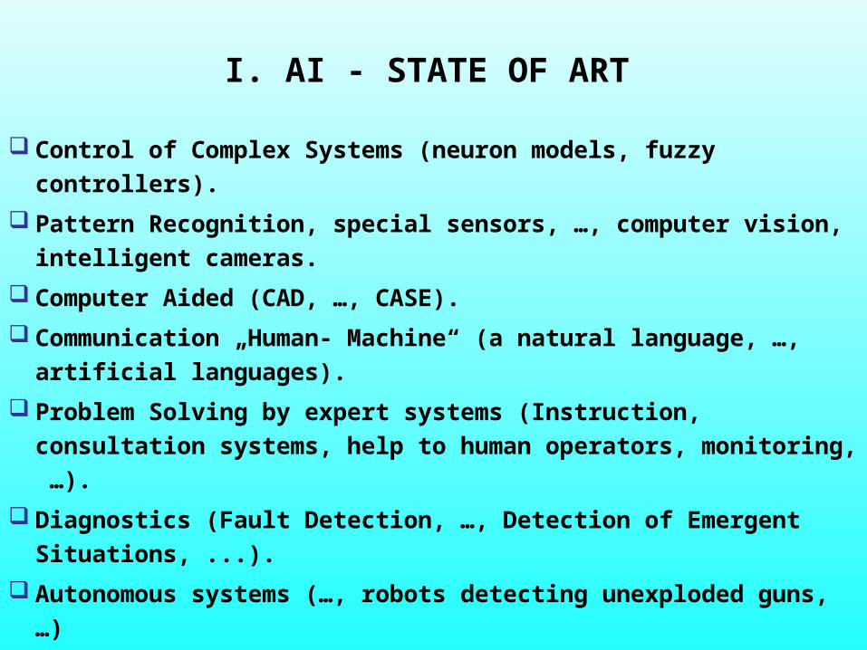
I. AI - STATE OF ART
Control of Complex Systems (neuron models, fuzzy controllers).
Pattern Recognition, special sensors, …, computer vision,
intelligent cameras.
Computer Aided (CAD, …, CASE).
Communication „Human- Machine“ (a natural language, …,
artificial languages).
Problem Solving by expert systems (Instruction, consultation
systems, help to human operators, monitoring, …).
Diagnostics (Fault Detection, …, Detection of Emergent
Situations, ...).
Autonomous systems (…, robots detecting unexploded guns, …)

II. Control of Complex Systems with hardly available models
Identification of Complex Systems by Artificial Neural Networks Life Cycle of ANN : Learning (training),Testing, Operation.
Training Sequence (sequence of training pairs)
Fuzzy modeling. Computing with uncertain variables and their values
Linguistic variables and linguistic values (e.g., temperature in the room, low,
higher, unpleasant, very high, …)
Fuzzy Controllers. Example of rule: IF(The control error is (Positive and Low) AND (The first
derivation of Control error is (Positive and High)) THEN (Action is (Negative
and Middle))

Identification of mathematical model of a parallel manipulator TRIPOD by a neural
network
Deployment of non traditional non
linear dynamic neural units for
identification of dynamics of
parallel manipulator TRIPOD
Parallel manipulator TRIPOD(VVZ J04/98 212200008, …, ČVUT )

Motivation for the development of Non Conventional Neural
Architectures
The unavailability of
information about the
analyzed system from a
trained network (e.g., a
differential equation,…)
High Complexity and a great number of neural parameters of conventional neural networks (MLP,RBF,…)
(?)fyi A conventional Neural Network ~
Black Boxix
1x
nx my
1y

Non linear dynamic neural units for the parallel manipulator
TRIPOD
n
i
u
u
u
1
),( Wxf
10 x
)(v
yv)( dt(.) dt(.)
2
1
0
1
x
x
x
u
u
u
n
i
x
2x
1x
v
v
),( Wxfy
Each leg is identified by an autonomous non linear dynamic neural unit HONNU.
3x

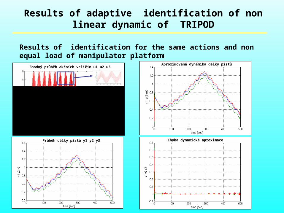
Results of adaptive identification of non linear dynamic of TRIPOD
Results of identification for the same actions and non equal load of manipulator platform
Shodný průběh akčních veličin u1 u2 u3
Průběh délky pístů y1 y2 y3
Aproximovaná dynamika délky pístů
Chyba dynamické aproximace

An example of dynamic system with Fuzzy controller
y
w
d
y
e
y
wdu/dt
de/dt
d
-0.4s+1
0.2s +1.2s+12
Transfer Fcn
t
y
Scope3
Scope
PI Fuzzy Logic Controller
Mux
Mux
s
11
Gain
Clock
y
w
d
y
e
y
wdu/dt
de/dt
d
-0.4s+1
0.2s +1.2s+12
Transfer Fcn
t
y
Scope3
Scope
PI Fuzzy Logic Controller
Mux
Mux
s
11
Gain
Clock

III. Pattern Recognition, special sensors, …, computer vision, intelligent cameras.
Development of Special Sensors.
Representation of external world by
means of artificial optical and tactile
signals. :
Sensors for surface pressure
(diagnostics of walking), tactile sensors,
sensors of force distribution in material
structures (e.g., in over loaded parts of
bones).
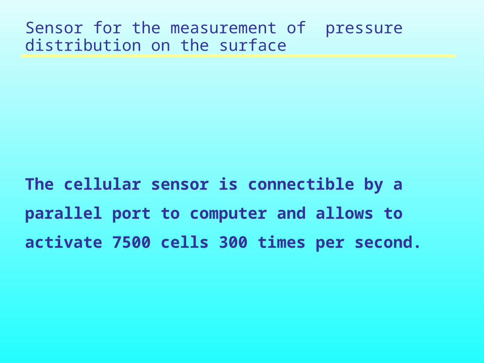
Sensor for the measurement of pressure distribution on the surface
The cellular sensor is connectible by a parallel port to
computer and allows to activate 7500 cells 300 times per
second.

IV. Computer Aided Design (CAD, CAPP,…, CASE).
Classification of design phases :
Early Design, Conceptual Design, Detailed Design
Classification of Design activities according to design objectives:
Construction and technology (CAD), Design of production phases „in small“ (CA
Production Planning), (CAM), Design of production phases „in large“ (CA
Manufacturing), Design of assembly phases (CA Assembly), Design of systems
for Quality Control (CA Quality Control), … , Design of Software products (CASE
- Computer Aided Software Engineering).
Classification of Design according to computer support:
Formal approach (Formal logic, expert systems), Deployment of special
methodologies and CASE systems, Evolutionary approaches (e.g., gradual
adaptation of prototypes. Genetic Algorithms).

IV.Design of Information and Control Systems (ICS).
Design of ICS - without use of special methodologies and SW support - only in
simple cases.
„ All designs end by a program“. Description of functions and activities of the
program needs a special formal means.
Integration of activities by methodologies and SW support: Concetration of
needed knowledge, analysis of information nvironment and controlled system,
design of a sceleton of ICS, generation of ICS program code.

Design of ICS by OMT (Object Modeling Technique,
(Rubmbaugh, 1991) and UML (Unified Modeling
Language (OMG, 1998)).
The OMT objective: To combine and to connect all important design phases from
the description in natural language, trough analysis and of designed ICS till the
design of ICS and generation of program code. UML is a Multi-dimensional graphic-symbolical language that continues OMT
methodology. UML has 8 modeling strata:
Use case model (1), Class Model (2), State Diagram(3), Interaction Diagram (4), Co-operation Diagram (5), Model of Activities (6), Component Model (7), Deployment Model (8).
Rough design scheme:
Basic description of the problem (Expert) Structured formulation of the problem (Knowledge Engineer) OMT methodology UML model Implementation (CASE system and code generation) Maintenance of the program product.

Example of „translation“ of a sentence in natural language into class diagram by OMT:
The sentence: „Center sf6 contains Jet Fans V515, …, V518 with reversation and 2 values control a Jet Fans V519 a V520 with reversation and continuously set up power.
Trf
statefan
SpustitF()SpustitRev()Zastavit()SetUp()staterfan()
Tjf
statefan
SpustitF()SpustitRev()Zastavit()SetUp()statefan()
Tsf6
V515 : TjfV516 : TjfV517 : TjfV518 : TjfV519 : TrfV520 : Trf
STATEsf6()

Design of ICS in Road Tunnel „Mrázovka“ in Prague. Application
of OMT, UML and Rational Rose CASE.
9 controlled
processes: Large
ventilation, Small
ventilation,
Transport, Security,
Energetics,
Maintanence,
Water sources, ...

Scheme of Road Tunnel Mrázovka in Prague
VTJh oooSF1
VTSr
B
VTSh
ZTS II
AJ
AS
ZTJr
VTJr
M5
M8
o SVK
M6
M7
M9
SF9ooo
M10
M11
M1
M3
oooSF2
M2
oooSF6
ZTS III
oooSF10
oooSF11
p2 o
ooooLSF1
ooooLSF2
Main Outputof Ventilation
N-PORT
oooSF3
SF4ooo
oooSF7
oooSF8
LSF3oooo
ZTJh
M4
o p1
o SVK
A
oLSF4

• Class and State diagram for center SF6
TI 5
Rem : stringRemVT : integerRemZT : integerLocFire : stringt1 : floatt2 : floatIntervalMea : floatdelta : float
OperGV()OperStart()OperOFF()OperFire()OperClose()OperManual()LocFire()
<<Interface>>
TI 6
COReq : floatOPReq : floatNOxReq : floatQReq : floatDPReq : floatCOON : floatOPON : floatOPFire : floatCOMain : floatOPMain : floatCOOFF : floatOPOFF : floatCOClose : floatOPClose : float
<<Interface>>
Trf
casONcasOFFcasON/OFFstatefan
StartF()StartRev()Stop()SetUp()timeON/OFF()staterfan()
Tjf
timeONtimeOFFtimeON/OFFstatefan
StartF()StartRev()Stop()SetUp()timeON/OFF()statefan()
Tsf6
V515 : TjfV516 : TjfV517 : TjfV518 : TjfV519 : TrfV520 : TrfstateV515 : stringstateV516 : stringstateV517 : stringstateV518 : stringstateV519 : stringstateV520 : string
STATEsf6()

MANUAL CONTROL
entry: Rem : = Manual
START
entry: V520.StartF
CONTROLOFF
do: t2:= now()do: delta:= t1- t2entry: V519.Stopentry: V520.Stopentry: V515.Stopentry: V516.Stopentry: V517.Stopentry: V518.Stop
TUNNEL CLOSED
FIRE
exit: OperClose
GV1
entry: V517.StartFentry: V519.StartF
GV2
entry: V516.StartFentry: V515.StartF
FireZTS
entry: V519.StartFentry: V520.StartFentry: V517.SetUpentry: V518.SetUpentry: V515.SetUpentry: V516.SetUp
OperManual
OperManual
OperManual
OperFire
[ V520.timeON/OFF > TimeRun ]
[ RemVT=0 ]
REV1
entry: V520.StartRev[ RemZT=3 ]
REV2
entry: V519.StartReventry: V517.StartReventry: V516.StartReventry: V515.StartRev
Branching
[ RemZT=0 ]
[ RemZT=7 ]
GV3
entry: V518.StartF
[ (RemZT=1)OR(RemZT=2) ]
[ RemZT=8 ]
[ RemZT=0 ]
OperFire
[ V517.timeON/FF > TimeRun ]
[ RemZT=3 ]
OperClose
[ (LocFire=VTJH)OR(LocFire=VTJR)OR(LocFire=VTTSr)OR(LocFire=B) ]
[ LocFire=ZTS ]
[ RemZT=7 ]
[ RemZT=0 ]
OperFire
[ V515.timeON/OFF>TimeRun ]
[ V520.timeON/OFF>TimeRun ]
[ RemZT=7 ]
[ RemZT=0 ]
[ RemZT=3 ]
[ (RemZT=1)OR(RemZT=2) ]
OperManual
[ RemZT=0 ]
OperFire
[ RemZT=3 ]
OperFire [ (RemZT=0)OR(RemZT=3) ]
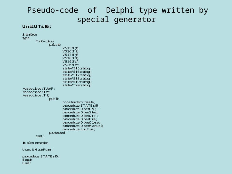
Pseudo-code of Delphi type written by special generator
Unit UTsf6;
interfacetype
Tsf6=classprivate
V515:Tjf;V516:Tjf;V517:Tjf;V518:Tjf;V519:Trf;V520:Trf;stateV515:string;stateV516:string;stateV517:string;stateV518:string;stateV519:string;stateV520:string;
//associace: TJetF;//associace: Trf;//associace: Tjf;
publicconstructor Create;procedure STATEsf6;procedure OperGV;procedure OperStart;procedure OperOFF;procedure OperFire;procedure OperClose;procedure OperManual;procedure LocFire;
protectedend;
Implementation
Uses UMainForm;
procedure STATEsf6;BeginEnd;

procedure OperGV;Begin
//ze stavového diagramu, MANUAL CONTROL ->
//ze stavového diagramu, START ->
End;
procedure OperStart;Begin
//ze stavového diagramu, MANUAL CONTROL -> STARTV520.SpustitF;
End;
procedure OperOFF;BeginEnd;
procedure OperFire;Begin
//ze stavového diagramu, START -> FIRE
//ze stavového diagramu, GV1 -> FIRE
//ze stavového diagramu, GV2 -> FIRE
//ze stavového diagramu, Branching -> FIRE
//ze stavového diagramu, Initial -> FIRE
//ze stavového diagramu, GV3 -> FIRE
End;
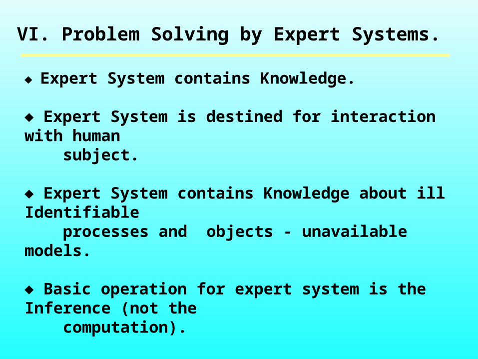
VI. Problem Solving by Expert Systems.
Expert System contains Knowledge.
Expert System is destined for interaction with human subject.
Expert System contains Knowledge about ill Identifiable processes and objects - unavailable models.
Basic operation for expert system is the Inference (not the computation).

Support of Problem Solving
System of instructions. The system manages a process by commands.
Qualitative models of actions„What/IF“.
Decision Support.
-Intuitive synthesis. - An ideal form of the support. - Compromising way: Formal logic.

Support of Problem Solving by Formal Logic
The description of all available knowledge that are relevant for the problem, the description of the environment of the problem and of the goal of the problem solution by the language of formal logic of the first order (FOL) or in the language of propositional logic.
Example of the formula: xy (P(x,y) Q(z)),
(P, Q … predicates, , … quantifiers, x, y, z … variables, … operator of logic implication).
The solution algorithm works with the only one partial task: „Verify, please, if the proposed goal formula „A“ is consistent (there are no contradictions) in the set of the problem description „“ !“ ( A)
There are special algorithms for verification of consistency A, (e.g., Theorem proving resolution Principle of Robinson (1953)).
There were developed special programming languages for SW support of problem solving by Theorem – languages of the type PROLOG, LISP, POP, … .
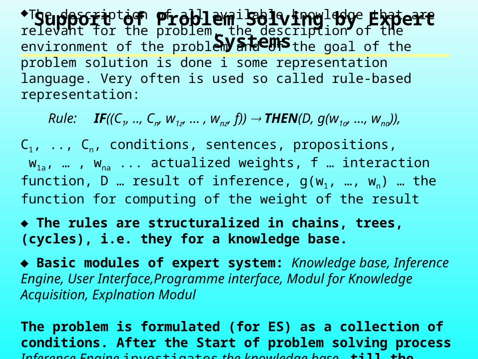
Support of Problem Solving by Expert SystemsThe description of all available knowledge that are relevant for the problem, the
description of the environment of the problem and of the goal of the problem solution is done i some representation language. Very often is used so called rule-based representation:
Rule: IF((C1, .., Cn, w1z, … , wnz, f)) THEN(D, g(w1a, …, wna)),
C1, .., Cn, conditions, sentences, propositions, w1a, … , wna ... actualized weights, f … interaction function, D … result of inference, g(w1, …, wn) … the function for computing of the weight of the result
The rules are structuralized in chains, trees, (cycles), i.e. they for a knowledge base.
Basic modules of expert system: Knowledge base, Inference Engine, User Interface,Programme interface, Modul for Knowledge Acquisition, Explnation Modul
The problem is formulated (for ES) as a collection of conditions. After the Start of problem solving process Inference Engine investigates the knowledge base till the state of satisfaction of the conditions.

The support of diagnostics by expert systems
Knowledge base consists of rules of the type:
IF((sp1= qi1 ) AND … AND (spn= qin )) THEN( Porucha pn),
sp1= qi1 means that symptom sp1 has value qi1 .
Classification of symptoms:
- overloading of technological limits (x TM), - analysis of signal morphology,
Example: Detection of faults in energetic system Herbertov
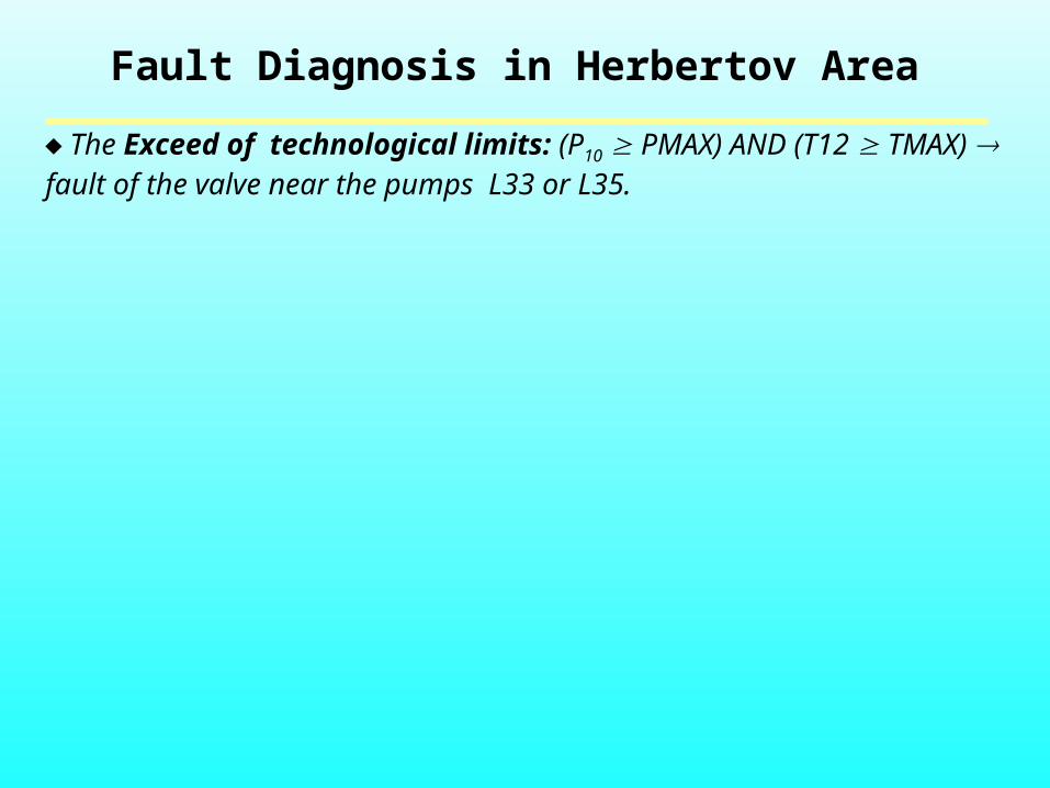
Fault Diagnosis in Herbertov Area
The Exceed of technological limits: (P10 PMAX) AND (T12 TMAX) fault of the valve near the pumps L33 or L35.
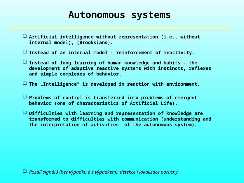
Autonomous systems
Artificial intelligence without representation (i.e., without internal model), (Brooksians).
Instead of an internal model - reinforcement of reactivity.
Instead of long learning of human knowledge and habits - the development of adaptive reactive systems with instincts, reflexes and simple complexes of behavior.
The „Intelligence“ is developed in reaction with environment.
Problems of control is transferred into problems of emergent behavior (one of
characteristics of Artificial Life).
Difficulties with learning and representation of knowledge are transformed to difficulties with communication (understanding and the interpretation of activities of the autonomous system).
Rozdíl signálů (bez výpadku a s výpadkem): detekce i lokalizace poruchy

Autonomous systems
Example of autonomous mobot AM (mobile robot) - The Centre of Gerstner (CG), Faculty of Electrical Engineering, CTU in Prague.

Means and strategies of AM CG

Example of searching for the trajectory between obstacles - AM CG

Conclusions
Artificial Intelligence (AI) is not the same as the natural intelligence.
There are the following successful fields of AI nowadays:
In theory:
Approximation disciplines as fuzzy control, neural networks and genetic algorithms.
Contributions to psychology and cognitive science. In practice:
Diagnostics,
Contributions to Computer Aided Engineering (CAE) and other CA… .
Consultation systems,
Autonomous systems (planetar moduls, …).

LITERATURA
1. P.H. Winston: Artificial Intelligence, MIT, Addison-Wesley Publishing Company, London, …, many additions from the first in 1977.2. Banerji, R.: Artificial Intelligence, …3. Nilson, S.: Artificial Intelligence, ...2. J.R. Brooks: Intelligence without representation. AI, No. 47, 1991. s. 139-1595. C. Langton: Artificial Life. Addison-Wesley Pub. Comp Inc., 1989.
6. A. Sloman: Can we design a Mind ? Keynote for AID 02 Conference, 2002. 7. K. Ueda: Emergent Synthesis. Artificial Intelligence in Engineering, No. 15, 2001. s. 319 - 327.
Address:
BÍLA Jiří, Prof. Ing. [email protected] , U 12110 FS ČVUT v Praze, Technická 4, 166 07 Praha 6

END


![MADE IN ITALY - novyinterier.cz1].pdf · MADE IN ITALY ID POINT CZECH, spol ... hala č. 12 S.K.Neumanna CZ-530 02 Pardubice Tel. 00420 466 655 084-6 Fax 00420 466 655 ... Picioare](https://img.pdfslide.tips/doc/110x75/5b829a5b7f8b9ae87c8ef23a/made-in-italy-1pdf-made-in-italy-id-point-czech-spol-hala-c-12-skneumanna.jpg)