Embed Size (px)
Citation preview

9/7/2017
1
Sandia National Laboratories is a multi-mission laboratory managed and operated by National Technology and Engineering Solutions of Sandia, LLC., a wholly owned subsidiary of Honeywell International, Inc., for the U.S. Department of Energy’s National Nuclear Security Administration under contract DE-NA0003525.
Asynchronous BallisticQuantum Computing
Michael P. FrankCenter for Computing ResearchSandia National Laboratories
Presented at the Quantum Coffee HourSandia National Laboratories, New Mexico
Thursday, September 7th, 2017
Approved for Public ReleaseSAND2017-9669 PE
Talk Outline Motivations:
Reducing control overheads in quantum computing
Asynchronous Ballistic Reversible Computing (ABRC) General network model
Examples of primitive devices
Universality construction
Superconducting implementations – Simulations from LPS!
A straightforward quantum generalization: ABQC
Implementation issues Stationary vs. flying qubits
Potential advantages and disadvantages of this model High decoherence rate?
Conclusion Towards a self‐contained, stored‐program quantum computer?
2

9/7/2017
2
Motivation What’s wrong with the usual models of quantum computing?
We traditionally envision that all primitive quantum gate operations are driven via direct external control (e.g., RF pulses) Introduces complexity in control interface (numerous control lines)
Control is a channel by which errors/decoherence can enter the system
Due to the implicit need for external control, the standard circuit model of a quantum computer does not represent a self‐contained physical artifact Difficult to analyze all of its physical properties
Hard to go directly from a specification of its function to its implementation
What might an alternative look like? Qubits flying ballistically between devices in a hardware circuit
Instead of “gates” representing operations, we have gates as actual devices.
A circuit denotes a network of connected devices, not an operation sequence.
Devices carry out local unitary transfomations automatically via a fixed, innate, designed‐in Hamiltonian…
– How precise and error‐free it can be may depend only on manufacturing quality…
No external control needed! Except maybe in occasional rounds of measurement‐based error correction.
3
The Need for Asynchrony But, there’s a problem if you want multiple ballistically‐flying
qubits to interact at a device… The dynamics implemented by the interaction with the device will
generally be sensitive to the relative time of arrival of different qubits… If multiple interacting qubits must arrive simultaneously, that requirement will essentially be impossible to satisfy…
– There will always be some finite uncertainty ∆t in the time of arrival of flying‐qubit entities with a finite standard deviation ∆E of energy
» and infinite ∆E is clearly unphysical
– Also, due to chaotic effects, timing uncertainties will tend to become exponentially amplified as flying qubits interact
Solution: Require the flying qubits to arrive at times that are widely separated
Negligible temporal overlap between arriving wavepackets
Device dynamics is essentially independent of exact qubit arrival times
This avoids chaotic amplification of relative arrival‐time uncertainties– Expect relatively modest increases in temporal uncertainty per interaction
4

9/7/2017
3
How to define this model? First, let’s back up a bit…
I first considered the problem of asynchronous ballistic network models in the context of classical reversible computing.
Motivation: Avoid the clocking overheads of driving adiabatic circuits.
However, the issues in developing the basic structure of the asynchronous ballistic network model are essentially the same in the classical reversible and quantum contexts. We’ll present the classical reversible version of the model, called
Asynchronous Ballistic Reversible Computing (ABRC), in some detail.
A paper on this will be presented at ICRC ‘17 in November
A straightforward generalization of the ABRC device model will then take us to the quantum model… Asynchronous Ballistic Quantum Computing (ABQC)
Appears to be a new concept—seems ripe for further exploration…
5
ABRC Model: Starting Requirements1. Universality – for reversible, and embedded irreversible
2. Network model – devices, bidirectional terminals, links
3. Localized signals (“pulses”)a. Spatial confinement – Along 1‐D signal paths (wires)
b. Temporal localization – Pulse width specified as bounded
4. Ballistic propagation – and at sufficiently large scales
5. Digital interpretation –m distinct signal types
6. Asynchrony – exact pulse arrival times not important
7. Determinism – future depends non‐randomly on past
Quantum version can generalize this in the usual way
8. Reversibility – over the assumed set of initial states
9. Quiescence – devices don’t change in between pulses
6
mM
t1 t2 t3
D1 D2
D5
D4
D6
D3
A
B
A
Bexact
alignment
Synchronousballistic:
Asynchronousballistic: S
gap >0
Some specified maximumallowable pulse width and/or
arrival-time uncertainty
9/7/2017
4
ABRC Model: Derived RequirementsThese follow from the starting requirements:
10. Non‐overlap of arriving pulses – Needed for determinism
11. Non‐overlap of departing pulses – Needed for reversibility
12. One‐to‐one correspondence between incoming and outgoing pulses– Necessary to carry away pulse energy/timing information
13. Statefulness – To do logic, devices must have a stable internal state.
14. The possible ABRC device behaviors are exactly characterized by (isomorphic to) a restricted set of Mealy machines:
I/O symbol alphabet consists of ⋅ compound signal characters:
Σ
where ∈ T , T ,… , T is any of I/O terminals, each multiplicity ,
and ∈ t , t , … , t is any of the signal types.
– Can easily generalize this to cases where not all all terminals have the same arity
Transition function : Σ → Σ is (conditionally) reversible Injective at least over some assumed subset ⊆ Σ of possible input syndromes
Machine implements an injective transformation of at least the subset of all input strings for which its assumed precondition for reversibility is met at each step
7
mTi
tj
ctT
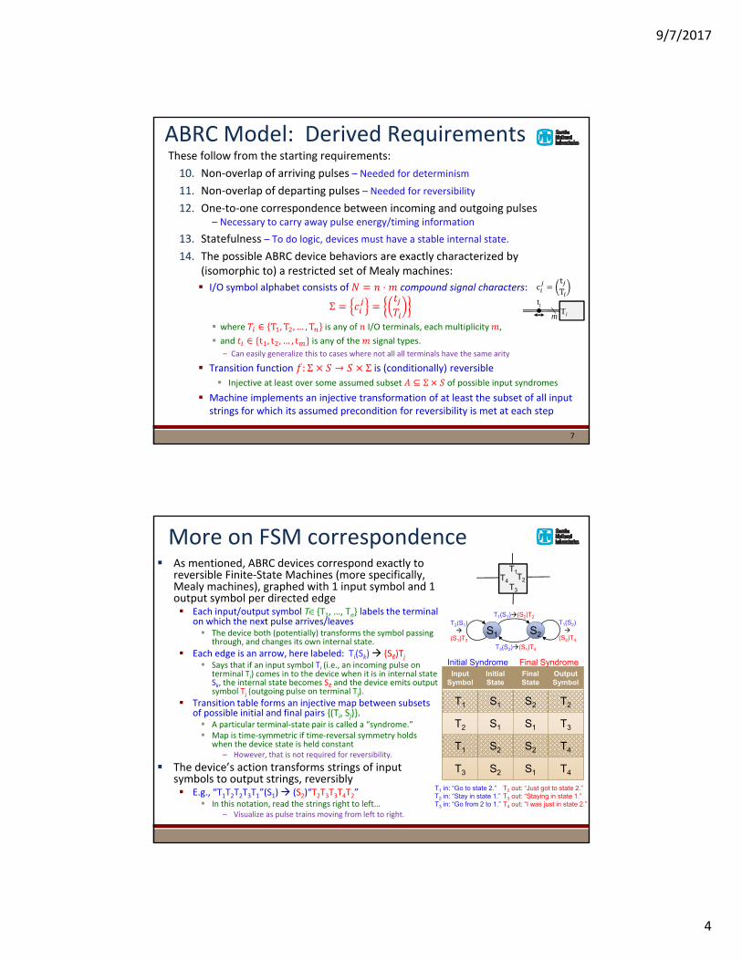
More on FSM correspondence As mentioned, ABRC devices correspond exactly to
reversible Finite‐State Machines (more specifically, Mealy machines), graphed with 1 input symbol and 1 output symbol per directed edge Each input/output symbol T{T1, …, Tn} labels the terminal
on which the next pulse arrives/leaves The device both (potentially) transforms the symbol passing
through, and changes its own internal state.
Each edge is an arrow, here labeled: Ti(Sk) (Sℓ)Tj Says that if an input symbol Ti (i.e., an incoming pulse on
terminal Ti) comes in to the device when it is in internal state Sk, the internal state becomes Sℓ and the device emits output symbol Tj (outgoing pulse on terminal Tj).
Transition table forms an injective map between subsets of possible initial and final pairs {(Ti, Sj)}. A particular terminal‐state pair is called a “syndrome.” Map is time‐symmetric if time‐reversal symmetry holds
when the device state is held constant– However, that is not required for reversibility.
The device’s action transforms strings of input symbols to output strings, reversibly E.g., “T1T2T2T3T1”(S1) (S2)“T2T3T3T4T2”
In this notation, read the strings right to left…– Visualize as pulse trains moving from left to right.
1S1 2S2
T1(S1)(S2)T2
T3(S2)(S1)T4
T2(S1)
(S1)T3
T1(S2)
(S2)T4
InputSymbol
InitialState
FinalState
OutputSymbol
T1 S1 S2 T2
T2 S1 S1 T3
T1 S2 S2 T4
T3 S2 S1 T4
T1 in: “Go to state 2.”T2 in: “Stay in state 1.”T3 in: “Go from 2 to 1.”
T2 out: “Just got to state 2.”T3 out: “Staying in state 1.”T4 out: “I was just in state 2.”
T1T2
T3
T4
Initial Syndrome Final Syndrome

9/7/2017
5
ABRC Primitives Here, we enumerate some simple unary ABRC primitives:
One‐terminal unary primitives:
Pulse Reflector (PR)
Two‐terminal unary primitives:
The one‐state, two‐terminal primitives:– Wire (W) a.k.a. signal renamer
» Functionally identical to a section of wire
– Barrier (B)
» Two pulse reflectors back‐to‐back
(Continued on next slide…)
9
A A
Simplified icon:
L R
A B
A BBout
ABSimplified notation:
Ain
ABRC Primitives, cont. Unary primitives, cont. Two‐terminal unary primitives, cont.
Two‐state, two‐terminal unary primitives:
– We can categorize them using these symmetry groups:
» T – Time‐reversal symmetry
» D – Data‐terminal reversal symmetry
» TS – Time/state reversal symmetry
– All nontrivial 2‐state, 2‐terminal unary devices can then be classified as follows:
» Devices with both T and D symmetries
Flipping Diode (FD) – Can use it as a memory!
» Devices with both D and TS symmetries
Anti-Flipping Diode (AFD)
Toggling Barrier (TB)
» Devices with none of these symmetries
Directional Flipping Diode (DFD)
Flipping Comparator (FC)
10
L RLin L R Rout
SR SL
L RSL
Lin L RLout
SL
Flipping Diode Behavior

9/7/2017
6
Flipping Diode: More Discussion
The only nontrivial two‐state, two‐terminal, time‐reversal‐symmetric (TRS) A.R. device The only other TRS two‐state, two‐
terminal AR devices are just barriers or renamers with redundant states
Equivalent to a reversible 1‐bit temporary memory cell (or delay element) with bidirectional I/O… With some signal routing/renaming,
this can also act as a reversible SR flip‐flop (reversible SRAM cell) useable in pipelined logic And if we also add a simple sequencing protocol, we can even make it into an asynchronous reversible AND gate!
L RLin L R Rout
InputSymbol
InitialState
FinalState
OutputSymbol
L SR SL R
L SL SL L
R SR SR R
R SL SR L
SR SL
L RSL
Lin L RLout
SL
Simplified icon
SRL SR L
SRR SR R
SLL SL L
SLR SL R
Notetime-
reversalsymmetry
Flipping Diode as Memory/Delay
Bundle the two terminals of the flipping diode into one dual‐rail signal, And we can see its function as a reversible memory/delay
element…
Let the dual‐rail bidirectional I/O signal be called “D” (for data bit), with values 0, 1 Encoded by pulses on the D0 and D1 lines respectively
Let the internal state variable of the flipping diode be called S, with values 0, 1 Encoded by states S0 and S1 for the up/down orientations of the
diode in this diagram, respectively
Then it’s easy to see that the function of this element can be described as follows: Dout = Sold; Snew = Din. I.e., exchange D↔ S.
(Output old value, store new value.)
Its operation on bit‐strings is to delay their data by 1 pulse.
DD0
D1
S1
D SSimplified icon
In: 0 0 1 1 1 0 0 0Out: 0 0 1 1 1 0 0 0
Time
on
no
ReversibleExchange
9/7/2017
7
Pout Pout
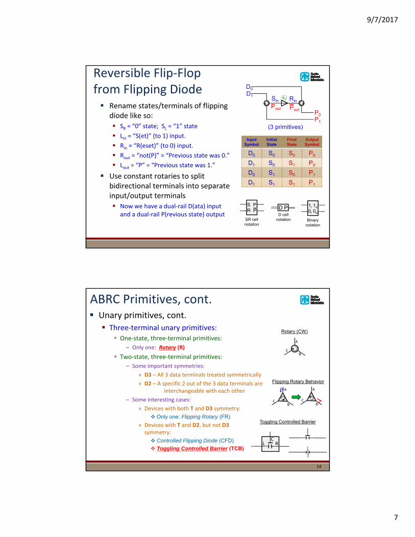
Reversible Flip‐Flopfrom Flipping Diode Rename states/terminals of flipping
diode like so: SR = “0” state; SL = “1” state
Lin = “S(et)” (to 1) input.
Rin = “R(eset)” (to 0) input.
Rout = “not(P)” = “Previous state was 0.”
Lout = “P” = “Previous state was 1.”
Use constant rotaries to split bidirectional terminals into separate input/output terminals Now we have a dual‐rail D(ata) input
and a dual‐rail P(revious state) output
S0Sin Rin
D1
D0
P1
P0
InputSymbol
InitialState
FinalState
OutputSymbol
D0 S0 S0 P0
D1 S0 S1 P0
D0 S1 S0 P1
D1 S1 S1 P1
S PR P
SR cellnotation
D cellnotation
D P 1i 1o
0i 0o
Binarynotation
(3 primitives)
ABRC Primitives, cont. Unary primitives, cont.
Three‐terminal unary primitives: One‐state, three‐terminal primitives:
– Only one: Rotary (R)
Two‐state, three‐terminal primitives:
– Some important symmetries:
» D3 – All 3 data terminals treated symmetrically
» D2 – A specific 2 out of the 3 data terminals are interchangeable with each other
– Some interesting cases:
» Devices with both T and D3 symmetry:
Only one: Flipping Rotary (FR)
» Devices with T and D2, but not D3 symmetry:
Controlled Flipping Diode (CFD)
Toggling Controlled Barrier (TCB)
14
A
BC
A
BC
A
BC
Flipping Rotary Behavior
L RC
Toggling Controlled Barrier
Rotary (CW)

9/7/2017
8
Universality Construction(slide 1 of 6)
Theorem: R, TCB comprises a universal set of primitives for reversible (and embedded irreversible) computing Constructive proof proceeds as follows:
1. Using two rotaries and a toggling controlled barrier,
– We can structure a toggling version of the reversible “switch gate” studied by Feynman and others
» We can then also build up a non‐toggling version of it…
Continued on following slides…
Ci Co
I
U
D
SU
SD
Block symbol
CoutCin
IU
DSD
SU
Toggling Switch Gate:
15
Universality Construction(slide 2 of 6)
Universality theorem, cont. Constructive proof, cont.
2. A toggling switch gate can be used as an asynchronous pulse (de)multiplexer
– Requires pre‐prepared supply of control pulses tho… ☹
» Still may be easier than fully-clocked adiabatic logic
» We may discover other universality constructions later that reduce the need for the pre-prepared control stream
16
D1
X2
U3
Y4
D1
X2
U3
Y4
X
Y (control& state implicit)
Simplified icon:
Asynchronous (De)Mux:

9/7/2017
9
Universality Construction(slide 3 of 6)
Universality theorem, cont. Constructive proof, cont.
3. A toggling switch gate plus a demuxcan make a pulse duplicator
– Produces incidental output (“garbage”)
» This can be cleaned up using the usual approaches (Bennett reversal)
17
X1
12X′2
X1X′3
¬X′2
×2X1X1 X′3
¬X′2
Simplified icon:
Pulse Duplicator:
Universality Construction(slide 4 of 6)
Universality theorem, cont. Constructive proof, cont.
4. With a pulse duplicator plus a toggling switch gate, we can build a non‐toggling switch gate
– Previously this gate was shown by Feynman and others to be universal!
» We’ll go ahead and show why…
18
×2C1C1 C3
D2
D2C
D2¬C
C1
D2C
D2¬C
Simplified Icon
D2
Non-toggling Switch Gate:

9/7/2017
10
Universality Construction(slide 5 of 6)
Universality theorem, cont. Constructive proof, cont.
5. E.g., the (non‐toggling) switch gate can be used to build a single‐rail to dual‐rail converter…
– This can also be considered as a NOT gate that also produces an extra (garbage) copy of its input
» Note we need the constant “1” pulse to be supplied…
19
12
A1
A2
¬A2
Single-rail to Dual-rail Converter:(Includes NOT function)
Universality Construction(slide 6 of 6)
Universality theorem, cont. Constructive proof, cont.
6. …and the switch gate can also be used to produce a reversible AND function
– Also produces as a garbage output
7. Standard techniques like Lecerfreversal and the Bennett trick can be applied to decompute all garbage,
– while leaving just the desired result and a copy of the input.
Thus, we can compute any Boolean function using an ABRC circuit made from {R, TCB} only. Q.E.D.
20
B2
A1
(AB)2
[(¬A)B]2
Asynchronous reversible AND gate:

9/7/2017
11
Remarks on Universality Construction
The above construction is sufficient for proving universality…
But, considered as a logic synthesis method, it clearly has some practical drawbacks…
This construction requires a great many control signals
Open research problem:
Find much simpler constructions for general functions
– Considering primitives other than {R, TCB} could be helpful
21
Physical realizations of ABRC? Of course, to be useful, this model needs to be realized in a specific
physical implementation technology that actually provides near‐thermodynamically‐reversible operation. Need some kind of soliton‐like, near‐ballistically‐propagating pulse,
or some sort of particle or quasiparticle.
Need some physical state variable that can stably maintain at least binary state for the toggling devices
Need a means of physically interacting the pulses with the states in ways that can reliably, and almost physically‐reversibly, implement at least a universal
subset of the 2‐ and 3‐terminal primitive devices.
One intriguing possible candidate implementation technology is to use superconducting circuits… SFQ (single flux quantum, or fluxon) pulses on appropriately constructed
superconducting transmission lines can carry info. with relatively low dispersion and high propagation velocity (approx. 1/3 c) Fluxons are naturally quantized by the SQUID‐like circuits that produce them, and are
naturally polarized (carry 1 bit’s worth of +/– polarization state information per pulse)– Need to select suitable ABRC primitives operating on arity‐2 signals
Fluxons trapped in loops (SQUID‐like structures) can hold data quiescently Generally, loops hold integer numbers of fluxons in some range: …, –2, –1, 0, +1, +2, …
How exactly to implement the reversible interactions? A 3‐year, internally‐funded project is just starting at Sandia to investigate this…
22

9/7/2017
12
A Very Recent Advance!
The circuit shown at right can be considered as a 2‐terminal ABRC device for binary pulses (fluxons) The specified function is to
preserve or flip the polarity of a fluxon passing through, depending on device parameters
Here, the “wires” are LJJ transmission lines Major loss mechanism is
resonant plasmon emission
With lattice spacing 0.4λ , fluxon decay time is ~107
junction switching times given initial 0.6 .
23
Wustman (LPS) & Osborn (JQI) ‘17 (preprint), “Efficient reversible logic gates without adiabatic constraint: Fluxon resonant scattering with polarity changes”
W&O’s paper also describes some more complex (4‐terminal) devices But they seemingly haven’t yet
explored asynchronous operation
W&O’s simulation of identity/NOT Direct numerical integration of
JJ circuit’s equations of motion Lagrangian:
Gives a discrete approximation to sine‐Gordon equation:
sin 0
Scattering interaction at interface is nearly elastic Loss in fluxon velocity of only 4%
Loss in energy of 2.1‐2.5%
24

9/7/2017
13
Matrix Representation of ABRC Device Behaviors Since the transition functions of
ABRC devices are (conditionally) reversible, Meaning that they are injective
maps from an assumed set of input syndromes onto an image set of output syndromes Their behavior when their
preconditions for reversibility are met can be described by unitary operators represented as zero‐one matrices
– Input vector space is spanned by the assumed set of input syndromes
– Output vector space is spanned by the image of the assumed set (may be the same set)
Here, we see an example matrix representation of the flipping diode’s device behavior
25
L RLin L R Rout
InputSymbol
InitialState
FinalState
OutputSymbol
L SR SL R
R SR SR R
L SL SL L
R SL SR L
SR SL
L RSL
Lin L RLout
SL
0 0 0 10 1 0 00 0 1 01 0 0 0
|LS
|LS
|RS
|RS
| S L
| S L
| S R
| S R
From ABRC to ABQC The obvious way to turn ABRC into a model of quantum
computation is then simply, allow device behaviors to be represented by arbitrary unitary
operations mapping from the (possibly restricted) input to output syndrome’s vector spaces
Somewhat akin to an S‐matrix describing a scattering event Device operation will generally result in superposition states in which
outgoing symbols (pulse locations) may be entangled with device state
Considering this model then raises an interesting open problem: What is a simple set of ABQC primitives that is universal for quantum
computation?
26

9/7/2017
14
ABQC Implementation Issues
Clearly, ABQC requires good‐quality (high fidelity, low decoherence rate) implementations of the following: Flying qubits (pulses) that propagate ballistically with low dispersion
and low decoherence rate
Stationary qubits (device states) that maintain their state stably over long periods with low error rate (high coherence time)
Interactions between stationary and flying qubits that carry out designed‐in unitary transition operations with high fidelity
Achieving the above is not an easy challenge… For high effective‐mass quasiparticles, decoherence rates may be high
for states involving superpositions of different spatial distributions of energy…
Gravitational interaction with environment, at least, is always present!
27
Conclusion We can describe a fairly straightforward circuit model for
asynchronous ballistic classical reversible computation… This is then straightforward to extend to produce a model of
asynchronous ballistic quantum computation.
The resulting model could theoretically reduce or avoid the need for externally‐supplied control, as devices could theoretically implement given unitaries automatically, via their own internal dynamics when flying qubits interact with them. However, the existing universality constructions for ABRC invoke prepared
streams of control pulses… Might it be possible to still demonstrate universality without this?
– If not for ABRC, then perhaps still for ABQC?
There are possible decoherence issues, but if the model can be made to work in practice, it offers several potential advantages… May reduce overheads associated with externally supplied control lines
Could offer much faster and more energy‐efficient operation
Could enable self‐contained, stored‐program quantum computers
28