Embed Size (px)
Citation preview
Generation Transmission DistributionUtilisation
By M.RamanathanDyCEE/LW/PER

Generation
Generation1. Conventional Power Stns:
Hydro, Thermal, Nuclear & Gas Turbine2. Non Conventional sources
1.1.1 Hydro Power StationSurge tank – to protect the penstock for bursting in case turbine gate closes suddenly.Valve house – Main sluice valve – controls the water flow
1.1.1 Hydro Power Station Auto isolating valve – cuts off when penstock bursts Power House – Turbines – Impulse (for high head) - Reaction (for low/med
head)Points to be considered for Hydro Stn: Availability of water Storage of water Cost & type of land Transportation facilities
1.1.2 Thermal Power Station
Boiler Super Heater Economiser Condenser
Cooling Tower Air Pre Heater Turbine + Alt Switch gear
Fuel – Uranium (U235), Thorium (Th232)1 kg of U235 fission = 4500t of coalModulator – slows down the neutrons before they bombardControl rod – regulates supply of neutrons for fissionHeat Exchanger – steam produced by hot metal and water
1.1.4 Gas Turbine
1.1.3 Nuclear Power Stn
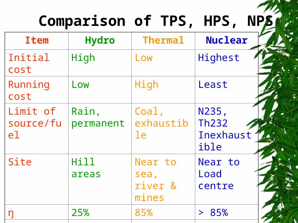
Comparison of TPS, HPS, NPSItem Hydro Thermal Nuclear
Initial cost High Low HighestRunning cost
Low High Least
Limit of source/fuel
Rain, permanent
Coal, exhaustible
N235, Th232 Inexhaustible
Site Hill areas Near to sea, river & mines
Near to Load centre
ŋ 25% 85% > 85%Cleanliness Most Less Medium

Non-conventional
sources
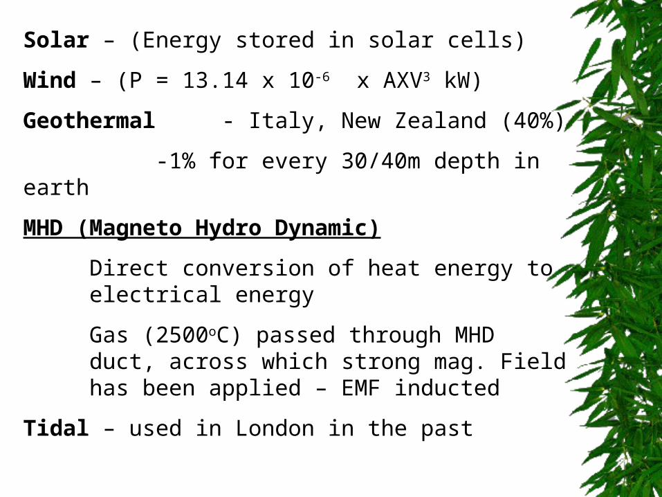
Solar – (Energy stored in solar cells)Wind – (P = 13.14 x 10⁻⁶ x AXV3 kW)Geothermal - Italy, New Zealand (40%)
-1% for every 30/40m depth in earthMHD (Magneto Hydro Dynamic)
Direct conversion of heat energy to electrical energyGas (2500oC) passed through MHD duct, across which strong mag. Field has been applied – EMF inducted
Tidal – used in London in the past
Economics of Power Station
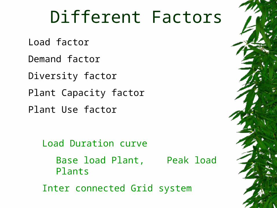
Different FactorsLoad factorDemand factorDiversity factorPlant Capacity factorPlant Use factor
Load Duration curveBase load Plant, Peak load Plants
Inter connected Grid system
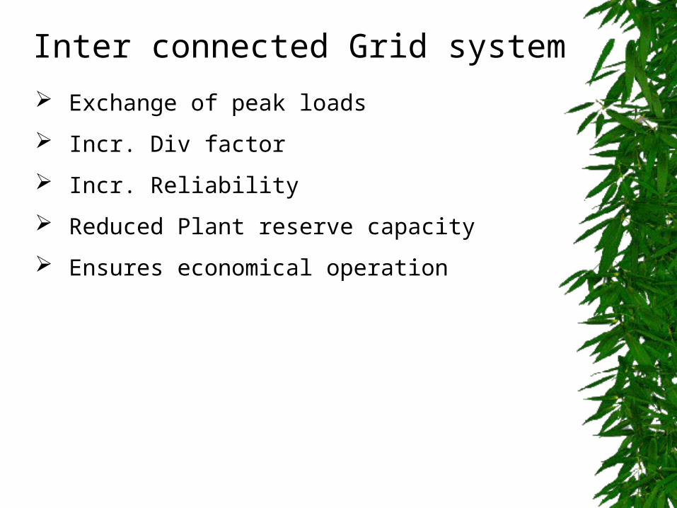
Inter connected Grid system Exchange of peak loads Incr. Div factor Incr. Reliability Reduced Plant reserve capacity Ensures economical operation
Transmission & Distribution
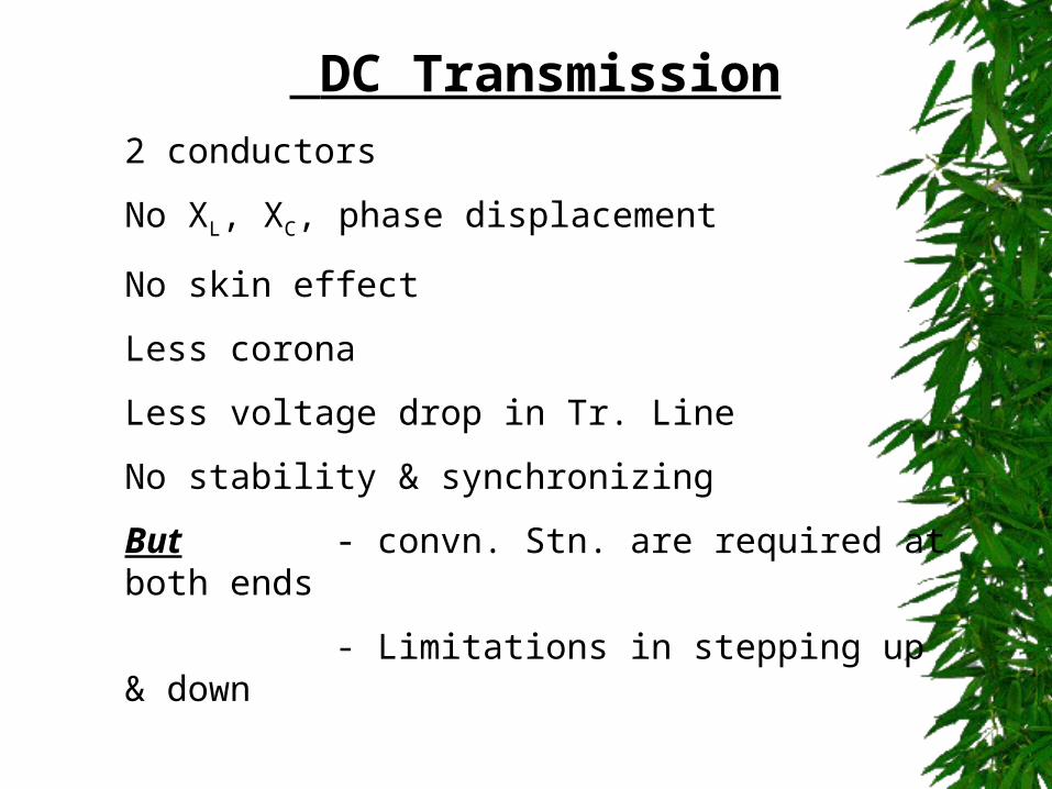
DC Transmission2 conductorsNo XL, XC, phase displacementNo skin effectLess coronaLess voltage drop in Tr. LineNo stability & synchronizingBut - convn. Stn. are required at both ends
- Limitations in stepping up & down
DC – 2 wire/2 wire with mid pt earthed
AC Transmission
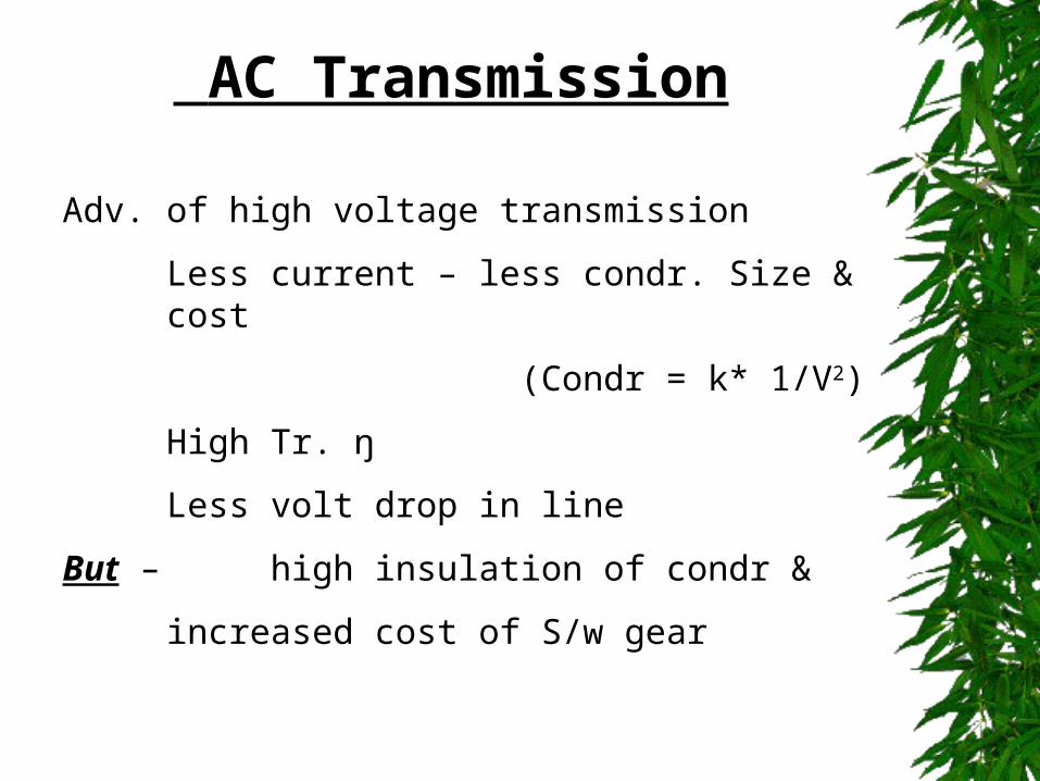
Adv. of high voltage transmissionLess current – less condr. Size & cost
(Condr = k* 1/V2)High Tr. ŋLess volt drop in line
But – high insulation of condr & increased cost of S/w gear
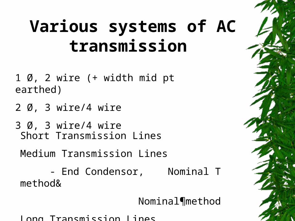
1 Ø, 2 wire (+ width mid pt earthed)2 Ø, 3 wire/4 wire3 Ø, 3 wire/4 wire
Various systems of AC transmission
Short Transmission LinesMedium Transmission Lines
- End Condensor, Nominal T method&
Nominal¶methodLong Transmission Lines
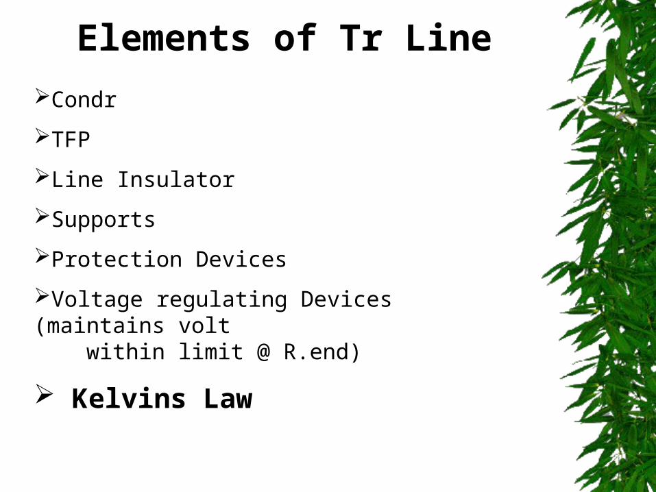
CondrTFPLine InsulatorSupportsProtection DevicesVoltage regulating Devices (maintains volt within limit @ R.end) Kelvins Law
Elements of Tr Line
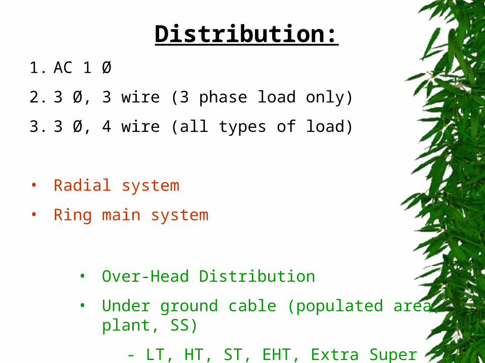
Distribution:1. AC 1 Ø 2. 3 Ø, 3 wire (3 phase load only)3. 3 Ø, 4 wire (all types of load)
• Radial system• Ring main system
• Over-Head Distribution• Under ground cable (populated area, plant,
SS)- LT, HT, ST, EHT, Extra Super Volt cables

Utilisation
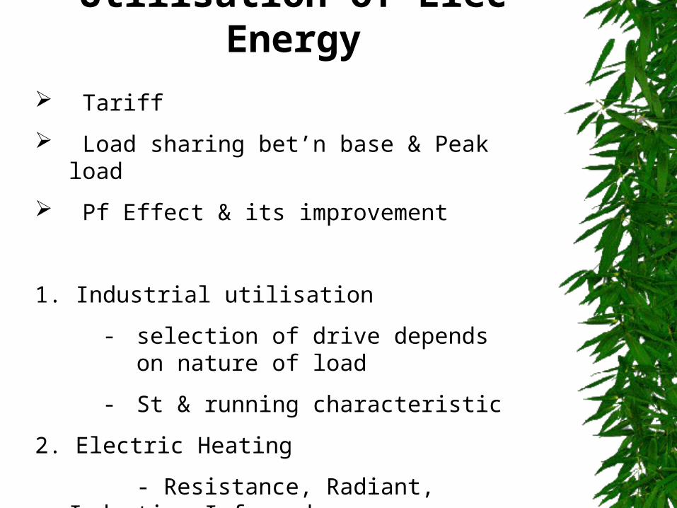
Tariff Load sharing bet’n base & Peak load Pf Effect & its improvement
1. Industrial utilisation- selection of drive depends on
nature of load- St & running characteristic
2. Electric Heating- Resistance, Radiant,
Induction,Infrared
Utilisation of Elec Energy
3. Induction, Arc furnaces4. Welding
- Resistance,Elec Arc, US, Electron beam
5. Illumination- difft types of lamps/factory,street lighting
6. Electrolytic process- Electrolysis, Electro deposition, etc
7. Refrigeration & A/C8. Traction
Utilisation of Elec Energy

Thank You